1
Nextor 2.0 Beta 2 Driver Development Guide
By Konamiman, 7/2013
Index
1. Introduction..................................................................................................................................................... 2
2. The Nextor kernel architecture........................................................................................................................ 2
2.1. The MSX-DOS 1 kernel............................................................................................................................ 2
2.2. The MSX-DOS 2 kernel............................................................................................................................ 3
2.3. The Nextor kernel..................................................................................................................................... 5
3. Creating a Nextor kernel with embedded driver .............................................................................................. 7
3.1. Manual creation ....................................................................................................................................... 7
3.2. Using the MKNEXROM utility ................................................................................................................... 8
3.3. Rules for the bank switching code ............................................................................................................ 9
4. Nextor driver structure ...................................................................................................................................10
4.1. Drive-based and device-based drivers ....................................................................................................10
4.2. Page 0 routines and data ........................................................................................................................11
4.3. The driver header ....................................................................................................................................13
4.4. Common routines ....................................................................................................................................14
4.5. Routines for drive-based drivers..............................................................................................................17
4.6. Routines for device-based drivers ...........................................................................................................22
4.7. Other .......................................................................................................................................................26
5. Change history ..............................................................................................................................................27
5.1. Beta 2 .....................................................................................................................................................27
5.2. Beta 1 .....................................................................................................................................................27
5.3. Alpha 2b..................................................................................................................................................27
5.4. Alpha 2....................................................................................................................................................27
6. Contact ..........................................................................................................................................................28
1
1. Introduction
Nextor is an enhanced version of MSX-DOS 2, the disk operating system for MSX computers. It is based on MSXDOS 2.31, with which it is 100% compatible.
This document provides a complete guide for programmers willing to develop storage device drivers for Nextor. It
is a good idea to get acquainted with Nextor by reading Nextor 2.0 Beta 2 User Manual prior to this document.
Also, although not strictly necessary, it is recommended to take a look at the Nextor 2.0 Beta 2 Programmers
Reference document, which is a reference of the new features that Nextor adds to MSX-DOS 2 from a developer
point of view other that the driver development.
WARNING: Nextor is in beta state. Although it has been reasonably tested, it could contain some bugs, so please
backup your valuable data before using it.
Note: The Nextor driver structure and rules are likely to evolve while Nextor is in beta state, this will usually be to
add support for new features.
2. The Nextor kernel architecture
This section explains some basic concepts about the Nextor kernel architecture, including a short explanation on
how the MSX-DOS kernel worked and how things have changed in Nextor. The information provided will help
driver developers to understand the context in which the driver code is executed.
2.1. The MSX-DOS 1 kernel
The original MSX-DOS kernel (labeled as version 1) was present as a ROM embedded in the external MSX floppy
disk controllers first, and later as an internal ROM in the MSX computers with built-in floppy disk drive as well. It is
a 16K ROM that uses the page 1 address space (addresses 4000h to 7FFFh) of its slot.
The MSX-DOS 1 kernel is divided in two main parts:
●
The kernel common code. It contains the hardware-independent code, such as the code for all the function
calls or the FAT filesystem management code. Most of the code in the ROM accounts for this part.
●
The disk driver. This is the code that physically accesses the massive storage devices, mainly to read and
write disk sectors, as requested by the kernel code when necessary. It consists of a series of routines with
standardized input and output parameters.
The kernel common code part is not 100% driver independent. It contains a couple of points that must be patched
depending on the disk driver used: one that specifies how many driver units will be controlled by the driver, and
another one that specifies how many page 3 work area is needed by the driver.
2
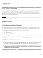
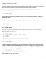
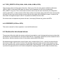
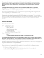
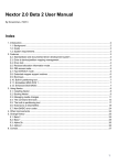
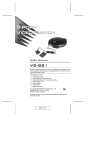
Figure 1 shows a diagram with the structure of a MSX-DOS 1 kernel.
4000h +---------------------+
|
|
|
|
|
|
|
Kernel
|
|
common code
|
|
|
|
|
+---------------------+
|
|
|
Disk driver
|
|
|
7FFFh +---------------------+
Figure 1 - MSX-DOS 1 kernel structure
A MSX computer can have up to four MSX-DOS kernel ROMs active. If more than one is present, then the one
with the smallest slot number becomes the “master” (the one whose kernel common code is actually executed),
and the others are the “slaves” (only their driver code is executed).
MSX-DOS views the storage devices as drive letters, while the disk driver presents one or more driver units. The
mapping between both entities is fixed and one-by-one, so for example drive A: is mapped to driver unit 0 of the
first kernel, drive B: is mapped to driver unit 1, and so on.
2.2. The MSX-DOS 2 kernel
The MSX-DOS 2 kernel first appeared as a cartridge with no associated storage hardware, and it was intended to
be used together with existing storage controllers associated to MSX-DOS 1 kernel. Later it was included
internally in MSX Turbo-R computers.
The MSX-DOS 2 kernel uses the page 1 address space of its slot, as the MSX-DOS 1 kernel does. However the
MSX-DOS 2 kernel has a size of 64K. This space is divided in four 16K banks and a bank mapping mechanism is
used so that only one of the banks is visible at the same time. The contents of the banks are as follows:
●
Bank 0 contains kernel common code and the disk driver code.
●
Banks 1 and 2 contain kernel common code.
●
Bank 3 contains a copy of the MSX-DOS 1 kernel, with a copy of the disk driver code (only in MSX TurboR machines).
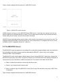
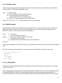
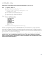
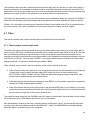
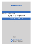
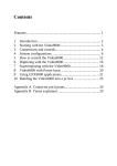
Figure 2 shows a diagram with the structure of a MSX-DOS 2 kernel.
3
Bank 0
Banks 1 and 2
Bank 3
4000h +---------------------+---------------------+---------------------+
|
Page 0 code
|
Page 0 code
|
|
40FFh +---------------------+---------------------+
|
|
0 (bank ID)
|
1/2 (bank ID)
|
|
4100h +---------------------+---------------------+
|
|
|
|
|
|
Bank 0
|
Banks 1/2
|
Bank 3
|
|
kernel code
|
kernel code
|
kernel code
|
|
|
| (MSX-DOS 1 kernel) |
|
|
|
|
+---------------------+
|---------------------+
|
|
|
|
|
Disk driver
|
|
Disk driver
|
|
|
|
|
7FD0h +---------------------+---------------------+---------------------+
| Bank switching code | Bank switching code | Bank switching code |
7FFFh +---------------------+---------------------+---------------------+
Figure 2 - MSX-DOS 2 kernel structure
There are three parts that are common to all banks (bank 3 contains the bank switching code only):
●
The page 0 code is 255 bytes long and contains an entry point for the timer interrupt routine, a routine for
calling code on another bank, and other useful utility code.
●
The bank ID is just one byte with the bank number, it is needed for doing inter-bank calls.
●
The bank switching code is needed for changing the visible bank. The exact code placed here depends on
the ROM mapper type used (the original DOS 2 cartridge mapping is ASCII16).
When booting in DOS 2 mode, bank 0 is permanently switched, and other banks are only temporarily switched
when bank 0 code needs to call a routine or access data on one of these banks. When booting in DOS 1 mode,
bank 3 is switched at boot time, and it remains switched forever.
As it was the case of the MSX-DOS 1 kernel, up to four MSX-DOS kernel ROMs can be active at the same time,
being one of them the “master” and the others the “slaves”. However, this time the master will not be the kernel
with the smallest slot number, but the kernel with the highest version number (the kernel with the smallest slot
number is still selected as the master in case of two or more kernels having the same version number).
4
2.3. The Nextor kernel
The Nextor kernel has an architecture that is based on the one of the MSX-DOS 2 kernel, but introduces
significant changes:
●
The number of banks has grown. In Beta 2 there is one extra bank for partition management code, and
two extra banks for the built-in partitioning tool.
●
The disk driver (“device driver” in Nextor terminology) code is no longer embedded at the end of the kernel
banks 0 and 3. Instead, now the driver has a whole bank for itself, which is located immediately after the
last bank of the kernel common code. If necessary, the driver can spawn across more than one bank.
●
The device driver structure is completely new. It of course contains routines to access storage devices, but
it also contains extensibility points so that it is easy to add BASIC extended commands (“CALL”
commands), extended BIOS commands, and a timer interrupt service routine.
●
The page 0 code has been modified to contain extra utility routines. These routines can be used by the
driver code.
●
A new information byte is added at address 4FFEh of all banks, which contains the size of the kernel
common code in 16K banks (alternatively, this value can be seen as the bank number of the driver).
●
The MSX-DOS 1 kernel at bank 3 has been modified (by adding the page 0 code and the bank Id,
amongst other things) so that it can perform calls to the device driver.
●
There is a 1K unused space at banks 0 and 3 (visible at addresses 7BD0h to 7FCFh). This space does not
contain any kernel code and can be used to put any code or data that is required by the driver to be here.
See section 4.7 for more details.
●
There are five entry points at kernel banks 0 and 3 (starting at addresses 7850h) that will be redirected to
another five entry points in the driver bank. This way, the driver can provide code that will be accessible
via direct inter-slot call to the kernel slot. See section 4.4.3 for more details.
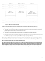
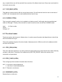
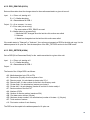
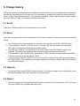
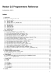
Figure 3 shows a diagram with the structure of a Nextor kernel.
5
Banks 0-(K-1)
Bank K
Banks (K+1)-... (optional)
4000h +---------------------+---------------------+---------------------+
|
Page 0 code
|
Page 0 code
|
Page 0 code
|
+---------------------+---------------------+---------------------+
40FEh |
K
|
K
|
K
|
+---------------------+---------------------+---------------------+
40FFh |
Bank ID
|
K (bank ID)
|
Bank ID
|
4100h +---------------------+---------------------+---------------------+
|
|
|
|
|
Bank
|
|
Additional
|
|
kernel code
|
Driver code
|
driver code
|
|
|
|
|
|
|
|
|
|
|
|
|
7BD0h +---------------------+
|
|
| Available 1K space |
|
|
| (on banks 0 and 3) |
|
|
7FD0h +---------------------+---------------------+---------------------+
| Bank switching code | Bank switching code | Bank switching code |
7FFFh +---------------------+---------------------+---------------------+
Figure 3 - Nextor kernel structure (“K” is the kernel common code bank count)
Nextor will use the same rule of MSX-DOS 2 to decide which kernel will be the master if more than one kernel is
found (the kernel with the highest version number will win). However this applies to other Nextor kernels only;
Nextor will always override other MSX-DOS 1 or 2 kernels present in the system, regardless of their version
number.
6
3. Creating a Nextor kernel with embedded driver
In order to create a complete Nextor kernel ROM that can be used in a MSX computer, up to four components are
needed:
●
The Nextor kernel base file. This file contains the kernel common code, that is, the “Banks 0-(K-1)” portion
shown in Figure 3. Its bank switching code is for the ASCII16 mapper (the original mapper used by the
MSX-DOS 2 kernel).
●
The device driver file. It must be created conforming to the rules and structure detailed in section 4. Its size
must be exactly 16080 bytes (16K minus the size of the page 0 code minus the size of the bank switching
code). If the driver spawns across more than one bank, this applies to each bank.
●
The bank switching code file (only if the mapper to be used by the target hardware is not ASCII16). This
code depends on the mapping type supported by the ROM cartridge where the complete kernel will be
burned. Compiled bank switching code files are provided for the ASCII8 and ASCII16 mappers; for other
type of mappers, custom code files must be made, following the rules detailed in section 3.3.
●
Optionally, the code that will be placed in the 1K unused space at banks 0 and 3 (see section 4.7 for more
details).
The procedure for creating the complete Nextor kernel ROM file consists basically on appending the driver code
the kernel base file, and then patching the resulting file with the appropriate bank switching code. This can be
done manually, or by using the MKNEXROM utility. Both options are explained below.
3.1. Manual creation
In order to manually create a complete Nextor ROM file, the following recipe must be followed. The file positions
mentioned are zero based.
1. Create a copy of the kernel base file (NEXTOR.BASE.DAT).
2. Append the page 0 code at the end of the file. This code can be simply copied from the first 255 bytes of
the kernel base file itself.
3. Append one byte with value K (the kernel base file bank count) at the end of the resulting file (this will be
the bank ID of the driver bank). The value of K can be read from position 254 of the kernel base file itself.
4. Append the driver file (which must be exactly 16080 bytes long, otherwise padding is required) at the end
of the file obtained in step 3.
5. Append the bank switching code at the end of the resulting file. If a file suitable for hardware supporting
the ASCII16 mapper is desired, then this code can be simply copied from the last 48 bytes of the kernel
base file itself. Otherwise, custom mapping code must be provided.
7
6. If the driver code does not fit in one single bank, repeat steps 2-5 to append extra banks, increasing the
bank ID for each bank as appropriate.
7. If necessary, patch the resulting file to add custom code or data at the 1K free space on banks 0 and 3.
Put the contents of the file (up to 1K long) twice, at positions 3BD0h and FBD0h in the file.
8. If the mapper type of the target hardware is not ASCII16, patch the bank switching code of the kernel
common code banks (the last 48 bytes of the first “K” 16K blocks of the resulting file, where “K” is the value
obtained in step 3) with custom bank switching code.
9. If the mapper type of the target hardware is not ASCII16, put the same custom bank switching code used
in steps 5 and 8 in the file position 2012.
The result of this procedure is a ready to use complete Nextor ROM file with your device driver properly
embedded. There is no need to further patch or otherwise modify the generated ROM file.
3.2. Using the MKNEXROM utility
Instead of manually performing all the steps needed to build a complete Nextor kernel ROM, it is usually more
convenient to use the supplied MKNEXROM utility. This tool can be used to create a new Nextor kernel ROM file,
but it also allows modifying an existing file by changing the mapper code and/or adding extra content in the free
1K areas present in banks 0 and 3.
MKNEXROM is supplied as a command-line executable file for Windows only, but the source code in standard C
is provided as well, so it should be easy to port it to other platforms.
The MKNEXROM tool usage syntax is as follows:
MKNEXROM <basefile> <newfile> [/d:<driverfile>] [/m:<mapperfile>]
[/e:<extrafile>]
<basefile> can be one of the following:
●
●
The Nextor kernel base file, that is, the file that contains the kernel common code only.
A complete Nextor kernel ROM file with the driver bank(s) already appended.
<driverfile> is the file containing the driver code. It must be a valid driver according to the rules and structure
explained in section 4. The contents of this file are expected to be as follows:
1.
2.
3.
4.
256 dummy bytes.
The driver signature
The driver jump table
The driver code itself
8
And optionally, if the driver spawns across more than one 16K bank, for each additional 16K block:
5. 256 dummy bytes.
6. The additional driver code or data.
7. Dummy space up to 16K (not needed for the last bank).
Specifying a driver file is mandatory if a kernel base file without driver is specified in <basefile>, and prohibited if a
complete kernel ROM file is specified.
<mapperfile> is the file containing the bank switching code. If no mapper file is specified, the mapper code from
the base file itself is appended to the driver code.
<extrafile> is the file containing the extra code or data for the resulting ROM file. This extra data can be up to 1K
long and will be placed at position 0x3BD0 of banks 0 and 3 at address 0x3BD0, this means that this code or
data will be visible to applications via standard inter-slot calls (such as RDSLT or CALSLT) to the kernel slot, at
address 0x7BD0. See section 4.7. for more details.
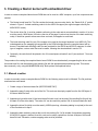
3.3. Rules for the bank switching code
If the mapper type of the target hardware where the resulting ROM will be burned is not ASCII16, then a file
containing compiled custom mapping code must be supplied. This code must follow the following rules:
1. It must be at most 48 bytes long.
2. It must switch in page 1 the 16K ROM bank whose number is passed in register A (banks are numbered
starting at zero). The ROM slot is assumed to be already switched on page 1.
3. It can corrupt register pair AF only. All other registers must be preserved.
4. It must be prepared to run at any address (so it can’t contain absolute jumps or references to itself).
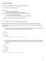
For illustration purposes, this is the source code of valid bank switching code for the ASCII8 mapper:
rlca
ld (6000h),a
inc a
ld (6800h),a
ret
9
4. Nextor driver structure
This section contains all the details needed in order to develop a device driver for Nextor. The necessary
elements, their locations, and the required routine input and output parameters are explained.
Note that the source code of a dummy driver (a valid driver that manages no devices) is supplied as well. You can
use that file as the skeleton for developing your own driver.
4.1. Drive-based and device-based drivers
When developing a Nextor device driver, the developer must choose between two driver styles: drive-based and
device-based.
Drive-based drivers have the same idiosyncrasy of MSX-DOS drivers for accessing the storage devices: they
expose a set of driver units and Nextor assigns one fixed drive letter for each unit; any necessary drive to device
or partition mapping must be performed by the driver itself. The set of routines for storage device access exposed
by these drivers is the same that was used by MSX-DOS drivers (DSKIO, DSKCHG, GETDPB, CHOICE,
DSKFMT and MTOFF).
Device-based drivers use a completely different approach. They do not expose driver units, but directly storage
devices. Also, they expose routines for raw access to the devices, and it is the Nextor kernel itself who manages
the drive to device and partition mapping.
In general it is recommended to develop device-based drivers, as the routines to implement are easier and the
driver code needs to just read and write absolute device sectors without having to worry about partitions; also, the
Nextor built-in device partitioning tool can be used to create partitions on devices controlled by device-based
drivers only. Developing a drive-based driver may however be a good option to easily convert an existing MSXDOS driver to Nextor.
Nextor will perform an automatic drive to device and partition mapping at boot time for the drives assigned to
device-based drivers, this mapping can be later modified by using the MAPDRV utility. More details are provided
in the Nextor 2.0 Beta 2 User Manual.
10
4.2. Page 0 routines and data
This section explains the routines and data that are available at page 0 (addresses 4000h-40FFh) of all the Nextor
banks, including the driver bank(s). These routines may be useful helpers for the driver code.
Remember that as explained in section 3, the page 0 code becomes part of all the driver banks when the
complete Nextor kernel ROM is generated.
4.2.1. GSLOT1 (402Dh)
Obtains in register A the slot currently switched on page 1 (that is, the slot of current driver code). Preserves all
other registers except F.
Note: This routine can't be called directly. It must be called via an inter-bank call to bank 0, in this way:
XOR A
LD IX,GSLOT1
CALL CALBNK
4.2.2. RDBANK (403Ch)
This routine reads a byte from another bank. It must be called via an inter-bank call to the bank to be read,
passing the address to be read in HL:
LD A,<bank number>
LD HL,<byte address> (must be a page 1 address)
LD IX,RDBANK
CALL CALBNK
It returns the read byte in A and preserves all other registers except F.
4.2.3. CALLB0 (403Fh)
This routine temporarily switches then kernel main bank (usually bank 0, but will be 3 when running in MSX-DOS
1 mode), then invokes the routine whose address is at (CODE_ADD). It is necessary to use this routine to invoke
CALBAS (so that kernel bank is correct in case of BASIC error) and to invoke DOS functions via F37Dh hook.
Input:
Address of code to invoke in (CODE_ADD).
AF, BC, DE, HL, IX, IY passed to the called routine.
Output: AF, BC, DE, HL, IX, IY returned from the called routine.
Note: the address of CODE_ADD is F84Ch.
11
4.2.4. CALBNK (4042h)
Calls a routine in another bank. This is useful if the driver spawns across two or more banks, and is needed for
using the GSLOT1, GWORK and RDBANK routines.
Input:
A = Bank number
IX = Routine address (must be a page 1 address)
AF' = Input parameter for the called routine
(will be passed as AF to the called routine)
BC, DE, HL, IY = Input parameters for the called routine
Output: AF, BC, DE, HL, IX, IY = Output parameters from the called routine
4.2.5. GWORK (4045h)
Gets the address of the 8 byte SLTWRK entry for the passed slot, or for the current slot in page 1. The first two
bytes of this area will contain a pointer to the allocated page 3 work area for this driver (as requested in the
DRV_INIT routine), or zero if no work area has been allocated.
Input:
A = Slot number
(0, for the current slot in page 1)
Output: A = Current slot switched on page 1 (if 0 at input)
Unchanged (if not 0 at input)
IX = Address of the 8 byte SLTWRK entry for the specified slot
Corrupts: F
Please see the description of DRV_INIT routine for an explanation about how to use this routine and the SLTWRK
area.
Note: This routine can't be called directly. It must be called via an inter-bank call to bank 0, in this way:
LD A,<slot number or 0>
EX AF,AF'
XOR A
LD IX,GWORK
CALL CALBNK
4.2.6. K_SIZE (40FEh)
This address contains one byte that tells how many banks form the Nextor kernel (or alternatively, the first bank
number of the driver).
When a driver spawns across more than one bank and needs to read data or call a routine in another driver bank
(by using RDBANK and CALBNK), it should calculate the bank number by adding the appropriate offset to
K_SIZE (or alternatively, to the value of CUR_BANK) instead of assuming a fixed bank number. When done this
12
way, compiled drivers can still be used with future versions of the Nextor kernel even if they have more banks for
the kernel common code.
4.2.7. CUR_BANK (40FFh)
This address contains one byte with the current bank number. For the first driver bank this value is the same of
K_SIZE, and it increases by one for each additional driver bank (if any).
4.2.8. CHGBNK (7FD0h)
This is not strictly a page 0 routine, but is available on all banks as well. It will simply make the specified bank
visible on Z80 page 1. Usually, driver code will not need to use this routine, but will use CALBNK instead.
Input:
A = Bank number
Output: Corrupts: AF
4.3. The driver header
The driver header is the first part of a Nextor driver. It contains some information that helps Nextor to identify the
driver and determine its type.
This section explains the parts of the driver header. Addresses start at 4100h since this is the address at which
the driver will be visible.
4.3.1. DRV_SIGN (4100h)
This is the valid driver signature, it is used by the kernel code at boot time to check that the driver bank effectively
contains a valid driver. It consists of the verbatim string "NEXTOR_DRIVER" (without the quotes), zeroterminated, and uppercased.
4.3.2. DRV_FLAGS (410Eh)
This is a flags byte that contains information about the driver:
bit 0: 0 = the driver is a drive-base driver
1 = the driver is a device-based driver
bits 1-7: Reserved, must be zero
4.3.3. RESERVED (410Fh)
Reserved byte, must be zero.
13
4.3.4. DRV_NAME (4110h)
This is a string containing the driver name. It must consist of 32 printable ASCII characters (ASCII codes 32 to
126). The string must be left justified and padded at the right with spaces.
4.4. Common routines
The next part of the driver is a jump table to a set of routines that are mandatory for all drives regardless of its
type (drive-based or device-based). Except for DRV_INIT, a driver does not need to provide a full implementation
of all of these routines, and usually it will be enough a simple RET instruction, sometimes returning an error code.
None of these routines need to preserve any of the registers not used to return data. The same applies to the
drive-based a device-based specific routines.
4.4.1. DRV_TIMI (4130h)
This is the entry point for the timer interrupt routine of the driver, it will be called 50 or 60 times per second
depending on the VDP frequency selected. If the driver does not need to handle the timer interrupt, it should fill
this entry with RETs.
Note that this entry will only called if DRV_INIT returns Cy=1 on its first execution. See the description of
DRV_INIT for more details.
4.4.2. DRV_VERSION (4133h)
This routine returns the driver version. Three version numbers must be returned, one byte each: main version
number, secondary version number, and revision number.
Input: Output: A = Main version number
B = Secondary version number
C = Revision number
14
4.4.3. DRV_INIT (4136h)
This is the driver initialization routine. It will be called by the kernel twice:
1. First execution, for information gathering.
Input:
A=0
B = Number of available drive letters
HL = Maximum size of allocatable work area in page 3
Output: A = Number of controlled drive units (for drive-based drivers only)
HL = Size of required work area in page 3
Cy = 1 if DRV_TIMI must be hooked to the timer interrupt, 0 otherwise
2. Second execution, for work area and hardware initialization.
Input: A = 1
B = Number of drive letters actually allocated for this controller
Starting at the second execution of this routine, the GWORK routine can be used at any time to obtain the
address of the space reserved for the current slot at SLTWRK. The driver should act as follows regarding the
page 3 work area:
●
If 8 bytes or less are required, this routine should return HL=0 on its first execution, and the 8 byte space
reserved by the system for this slot at SLTWRK should be used as work area:
XOR A
EX AF,AF'
XOR A
LD IX,GWORK
CALL CALBNK
;Use the 8 byte space pointed by IX as work area
●
If more than 8 bytes are required, this routine should return the required space in HL, and should obtain
the pointer to the allocated space from the first two bytes of the space reserved by the system for this slot
at SLTWRK:
XOR A
EX AF,AF'
XOR A
LD IX,GWORK
CALL CALBNK
LD L,(IX)
LD H,(IX+1)
;Use the space pointed by HL as work area
15
Please note also the following:
●
If the first execution requests more page 3 work area than available, the second execution will not be
done, no drives will be allocated and DRV_TIMI will not be hooked to the timer interrupt; in other words,
Nextor will ignore the involved controller. The size of the work area required should always be within the
available limits.
●
For drive-based drivers, the operating system will assign to the driver as many drive letters as driver units
are controlled. However, if there are more drive units than drive letters are available, then as many drives
as possible will be allocated, and the initialization procedure will continue the normal way. This applies to
device-based drivers too, except that Nextor will always try to allocate two drive letters for these drivers.
●
For drive-based drivers: unlike MSX-DOS, the timer interrupt routine will be executed (if requested) even if
the driver has zero driver units.
4.4.4. DRV_BASSTAT (4139h)
This is the entry for the BASIC extended statements ("CALLs") handler. It works the same way as the standard
handlers (see MSX2 Technical Handbook, chapter 2, for details), except that if the handled statements have
parameters, the MSX BIOS routine CALBAS (needed to invoke the MSX BASIC interpreter helper routines) can’t
be used directly; instead, it must be invoked via the CALLB0 entry in kernel page 0.
If the driver does not handle BASIC extended statements, it must simply set the carry flag and return.
4.4.5. DRV_BASDEV (413Ch)
This is the entry for the BASIC extended devices handler. It works the same way as the standard handlers (see
MSX2 Technical Handbook, chapter 2, for details), but see the note on DRV_BASSTAT about CALBAS.
If the driver does not handle BASIC extended devices, it must simply set the carry flag and return.
4.4.6. DRV_EXTBIO (413Fh)
This is the extended BIOS handler. It works the same way as the standard handlers, except that it must return a
value in D' (D in the alternative registers set) that tells the kernel what to do after the driver handler has finished:
D'=0: Return immediately.
D'=1: Execute the kernel and/or the system extended BIOS handler.
The driver extended BIOS handler is always entered with D'=1. Therefore, if the driver does not handle extended
BIOS at all, it can simply fill this entry point with RETs.
16
4.4.7. DRV_DIRECT0/1/2/3/4 (4142h, 4145h, 4148h, 414Bh, 413Eh)
These are the entries for direct calls to the driver. Calls to any of the five entry points available at addresses
7850h to 785Ch in the kernel ROM (bank 0 or bank 3) will be mapped to a call to the corresponding
DRV_DIRECT entry point. This is useful when the driver wants to provide extra functionality for configuration,
returning information, or other purposes. When these routines are entered, paging state will be the same as when
the bank 0/3 entry was invoked, except of course that the driver bank will be switched on page 1 instead of the
kernel bank. All registers except IX and AF' are passed unmodified from the caller.
If the driver does not implement any direct call code, it can simply fill these entry points with RETs.
4.4.8. RESERVED (4152h to 415Fh)
This area is reserved for future expansion, it must be filled with zeros.
4.5. Routines for drive-based drivers
The next part of the driver after the common routines is jump table to a set of storage device access routines that
are different for drive-based drivers and device-based drivers. This section explains the routines needed for drivebase drivers, which are actually a clone of the routines used by MSX-DOS drivers.
Drive-based drivers are assumed to control N drive units, numbered from 0 to N-1, where N is returned by the
driver when its DRV_INIT routine is invoked. The operating system will assign one drive letter directly to each
drive unit, therefore drive units are expected to always hold a valid filesystem. It is the responsibility of the driver
to perform the appropriate drive unit to device and partition mapping (perhaps with the help of external tools).
17
4.5.1. DRV_DSKIO (4160h)
Reads or writes sectors from the massive storage device associated to a given driver unit.
Input:
A = Driver unit, starting at 0
Cy = 0 for reading sectors, 1 for writing sectors
B = Number of sectors to read/write
C = First sector number to read/write (bits 22-16) if bit 7 is not set
Media ID byte if bit 7 is set
DE = First sector number to read/write (bits 15-0)
HL = source/destination address for the transfer
Output: Cy = 0 on success, 1 on error
A = Error code (on error only):
0 Write protected
2 Not ready
4 Data (CRC) error
6 Seek error
8 Record not found
10 Write fault
12 Other errors
B = Number of sectors actually read (in case of error only)
Unlike the counterpart of this routine in the old MSX-DOS drivers, this routine will never receive a request to
transfer data from/to page 1. If the kernel code requires data to be transferred to page 1, it will split the transfer in
several 1 sector transfers and use a temporary buffer in page 3; the driver code does not need to worry about this
and can do always direct transfers from/to memory.
If Nextor detects that the drive contains a FAT16 filesystem, then register C will be used to hold bits 22 to 16 of
the sector number, thus the complete sector number will be a 23 bit value hold by registers CDE. Otherwise,
register C will contain the device media ID (which will always have its MSB set), and the complete sector number
will be a 16 bit value hold by registers DE.
18
4.5.2. DRV_DSKCHG (4163h)
Returns information about the change status for the media associated to a given driver unit.
Input:
A = Driver unit, starting at 0
B = C = Media descriptor
HL = Base address for DPB -1
Output: Cy = 0 on success, 1 on error
A = Error code (on error only)
The same codes of DRV_DSKIO are used
B = Media status (on success only)
1 Media has NOT changed since the last time this routine was called
0 Unknown
-1 Media has changed since the last time this routine was called
If the media status is "Changed" or "Unknown", the routine must generate a DPB for the disk and copy it to the
address passed in HL plus one. See the description of the DRV_GETDPB routine for the DPB format.
4.5.3. DRV_GETDPB (4166h)
Gets a DPB (Drive Parameters Block) for the media associated to a given driver unit.
Input:
A = Driver unit, starting at 0
B = C = Media descriptor
HL = Base address for DPB -1
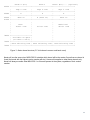
Output: The format of the 18 byte DPB is as follows:
+00:
+01:
+03:
+04:
+05:
+06:
+07:
+08:
+0A:
+0B:
+0D:
+0F:
+10:
Media descriptor byte (F0h to FFh)
Sector size (2 bytes), must be a power of two
Directory mask, it is calculated as (sector size /32)-1
Directory shift, it is the number of one bits in the directory mask
Cluster mask, it is calculated as (sectors per cluster)-1
Cluster shift, it is calculated as (number of one bits in cluster mask)+1
Sector number of the first FAT
Number of FATs
Number of directory entries (maximum 254)
First data sector number (2 bytes)
Maximum cluster number, it is calculated as (number of clusters +1) (2 bytes)
Total number of sectors
First sector number of root directory
The DPB must be copied to the address passed in HL plus one.
19
4.5.4. DRV_CHOICE (4169h)
Returns a format choice string for a disk.
Input: Output: HL = Address of the choice string in the kernel slot
This routine is called by the kernel code when a FORMAT command is executed, in order to show the formatting
options to the user (in MSX-DOS 2 and Nextor, it is also called by the CHOICE function call). The value returned
in HL is the address of a zero terminated string with formatting choice options to be shown to the user; this string
must be present in the kernel slot and must be readable with the RDSLT routine or an equivalent method. There
are three cases that are supported without any modification needed in the kernel base code:
1. If the disk supports only one kind of formatting (that is, there is actually no choice), it must return HL = 0.
1. If the disk does not support formatting (the most common case), it must return HL = 781Fh. This is the
address of a null string available in the kernel banks 0 and 3.
2. If the device is a legacy MSX floppy disk drive that handles single sided and double sided disks, it must
return HL = 7820h. This is the address of a "Single sided / Double sided" string available in the kernel
banks 0 and 3.
If any other string is to be returned, then it must be stored at the free 1K space that is available at kernel pages 0
and 3 (see section 4.7 for details).
4.5.5. DRV_FORMAT (416Ch)
Formats a disk and initializes its boot sector, FAT and root directory.
Input: A = Formatting choice, from 1 to 9 (see DRV_CHOICE).
D = Drive unit, starting at 0
HL = Address of work area in memory
DE = Size of work area
Output: Cy = 0 on success, 1 on error
A = Error code (on error only):
0 Write protected
2 Not ready
4 Data (CRC) error
6 Seek error
8 Record not found
10 Write fault
12 Bad parameter
14 Insufficient memory
16 Other errors
20
This routine performs the actual disk formatting according to the formatting choice passed in register A, which is
assumed to have been selected by the user after the choice string returned by DRV_CHOICE has been
displayed.
The "work area" is a RAM space provided by the caller that can be freely used by the formatting routine if
necessary.
4.5.6. DRV_MTOFF (416Fh)
Stops the motor of all the managed drives. This routine makes sense for floppy disk drives only; for other types of
devices it should do nothing. This routine has no input or output parameters.
21
4.6. Routines for device-based drivers
This section explains the driver routines that are needed for device-base drivers. Note that the jump table entries
for these routines use the same addresses as the routines for drive-based drivers; this makes sense because a
driver will only implement one of the two sets of routines.
Device-based drivers do not use the concept of drive units mapped directly to drive letters; instead, these drivers
provide raw access to storage devices, and it is the Nextor kernel itself who manages the drive to device and
partition assignment, both automatically (at boot time) and manually (on behalf of the user, via tools that use the
new Nextor function calls).
Device-based drivers can control up to seven storage devices, identified with an index number that ranges from 1
to 7. Each device has in turn from one to seven logical units, identified too with an index number from 1 to 7 (for
example, a multimedia card reader with several slots could expose each slot as a separate logical unit). Devices
may not physically be divided in logical units (this will be actually the most common case), in this case the driver
must expose the device as having one single logical unit with index number 1.
4.6.1. DEV_RW (4160h)
Reads or writes absolute sectors from/to a device.
Input:
Cy = 0 to read sectors
1 to write sectors
A = Device index, 1 to 7
B = Number of sectors to read or write
C = Logical unit index, 1 to 7
HL = Source or destination non-page 1 memory address for the transfer
DE = Non-page 1 memory address where the 4 byte sector number is stored
Output: A = Error code:
0: Ok
.IDEVL: Invalid device or logical unit number
.NRDY: Not ready
.DISK: General unknown disk error
.DATA: CRC error when reading
.RNF: Sector not found
.UFORM: Unformatted disk
.WPROT: Write protected media, or read-only logical unit
.WRERR: Write error
.NCOMP: Incompatible disk
.SEEK: Seek error
B = Number of sectors actually read (in case of error only)
This routine allows reading and writing sectors from/to a device. Note that what this routine must access is the raw
physical device sectors, not partition sectors. The driver does not need to know anything about device partitioning.
22
The number of the first sector to read or write is a 32 bit number which is supplied in a memory area whose
address is pointed by DE. This address will never be on page 1, therefore the drivers does not need to worry
about paging and can access this data directly. The same applies to the sectors data source or destination
address.
The available sector numbers must range from zero to the number of available sectors (as reported by
LUN_INFO) minus one. If LUN_INFO reports zero available sectors, then the range of available sectors is
undefined unless the driver developer explicitly documents it.
This routine must work for all block devices. If a non-block device supports reading and/or writing sectors, this
routine may optionally work with that device as well.
The error codes returned are the same used by MSX-DOS 2, as listed under the category "Disk errors" in the
MSX-DOS 2 Program Interface Specification document. The .IDEVL error is new in Nextor and has a code of B5h;
the complete list of new error codes defined by Nextor is in the Nextor 2.0 Beta 2 Programmers Reference
document.
4.6.2. DEV_INFO (4163h)
Returns information about a device.
Input:
A = Device index, 1 to 7
B = Information to return:
0: Basic information
1: Manufacturer name string
2: Device name string
3: Serial number string
HL = Pointer to a buffer in non-page 1 RAM
Output: A = Error code:
0: Ok
1: Device not available, information not available, or invalid information index
This routine is used by the kernel code to check the availability of storage devices and to get general information
about them. The “Basic information” block is mandatory (it must be not available only when the device itself is not
available), all other information blocks are optional and must return an error if not available.
The address passed in HL will never be on page 1, therefore the drivers does not need to worry about paging and
can generate the data directly at the specified address.
When basic information is requested, the buffer supplied in HL must be filled with the following information:
+0 (1): Number of logical units, from 1 to 8.
1 if the device has no logical units (which is functionally equivalent to having only one).
+1 (1): Device features flags. This must be zero in Beta 2.
23
All other information blocks have the form of text strings. These must be printable ASCII strings (containing ASCII
codes 32 to 126 only), left justified and padded with spaces.
If a string is provided by the device in binary format, the driver should return it as an hexadecimal, upper-cased
string, preceded by the prefix "0x".
The maximum length for a string is 64 characters. If the string is actually longer, the leftmost 64 characters must
be provided.
In the case of the serial number string, the same general rules for the strings apply, except that it must be
provided right-justified, and if it is too long, the rightmost characters must be provided, not the leftmost.
The driver must never provide the same combination of manufacturer name, device name and serial number for
two different devices. Hard-coded serial numbers should never be returned; if the driver is not able to obtain a
serial number from the device itself, it should return no serial number at all.
4.6.3. DEV_STATUS (4166h)
Obtain the availability and change status for a device or logical unit.
Input:
A = Device index, 1 to 7
B = Logical unit number, 1 to 7
0 to return the status of the device itself
Output: A = Status for the specified logical unit, or for the whole device if 0 was specified:
0: The device or logical unit is not available, or the device or logical unit number supplied is invalid.
1: The device or logical unit is available and has not changed since the last status request.
2: The device or logical unit is available and has changed since the last status request.
(for devices, the device has been unplugged and a different device has been plugged
which has been assigned the same device index;
for logical units, the media has been changed).
3: The device or logical unit is available, but it is not possible to determine
whether it has been changed or not since the last status request.
This routine tells the media change status for a device. Nextor will normally call this routine only for the logical
units with the “removable” flag set in the information block returned by LUN_INFO; however the routine will be
called for fixed logical units as well when running in MSX-DOS 1 mode (for fixed logical units, this routine should
always return either 0 or 1 in A).
In Nextor Beta 2 this routine will never be called with B=0 (check the status of the device itself). Support for hotplug device systems such as the USB bus is planned for a future version.
Nextor uses a boot sector checksum mechanism to manage device changes when drivers return A=3 in response
to a call to DEV_STATUS (see Nextor 2.0 beta 2 User Manual, section “Managing media changes”, for details). In
order to avoid boot sector reads and checksum calculations, drivers should return proper device change
information (that is, DEV_STATUS should return A=1 or 2 instead of 3) whenever possible.
24
Important note: the status returned by this routine is always relative to the previous invocation of the same routine.
Calls to DEV_RW must NOT cause the next call to DEV_STATUS to return A=1 if the device has changed. In
other words, in the sequence of: media change – call to DEV_RW – call to DEV_STATUS, the last call must
return A=2. This behavior is necessary for a proper operation of the Nextor drive mapping engine.
The value returned by this routine at the first invocation at system boot (after DRV_INIT is invoked) is irrelevant,
that is, if a device is available then either A=1 or A=2 may be returned.
4.6.4. LUN_INFO (4169h)
Obtain information for a logical unit.
Input:
A = Device index, 1 to 7
B = Logical unit index, 1 to 7
HL = Pointer to buffer in non-page 1 RAM
Output: A = 0: Ok, buffer filled with information
1: Error, device or logical unit not available, or invalid device index or logical unit number supplied
This routine must return a certain information about the given logical unit for a device. The address passed in HL
will never be on page 1, therefore the drivers does not need to worry about paging and can generate the data
directly at the specified address.
The information to be returned is a 12 byte block with the following structure:
+0 (1): Medium type:
0: Block device
1: CD or DVD reader or recorder
2-254: Unused (reserved for future use)
255: Other type
+1 (2): Sector size, 0 if this information does not apply or is not available
+3 (4): Total number of available sectors, 0 if this information does not apply or is not available
+7 (1): Logical unit features flags:
bit 0: 1 if the medium is removable
bit 1: 1 if the medium is read only
bit 2: 1 if the logical unit is a floppy disk drive
bits 3-7: Unused, must be zero
+8 (2): Number of cylinders
+10 (1): Number of heads
+11 (1): Number of sectors per track
"Block devices" are all devices that can be read and written via access to logical sectors. This includes floppy
disk, hard disks, pendrives, multimedia cards, etc. Block devices must be readable and optionally writable via the
DEV_RW routine.
In Beta 2 Nextor will refuse to work with a device that is reported as a non-block device or having a sector size
different from 512 bytes. Support for direct filesystem access is a planned feature for a future version.
25
The information about cylinders, heads and sectors per tracks apply only for hard disk; for other device types, or
when this information is not available for whatever reason, these fields should be returned with value zero. This
information is not used by the Nextor kernel, but can be used by device partitioning tools in order to properly align
partitions on the disk (in Beta 2 this information is not used by the built-in partitioning tool).
The "read only" flags should be set only for devices that are only readable by design (for example a CD-ROM). A
device that can be dynamically write protected and write enabled should not be reported as a read-only device.
In Beta 2 it is not possible to format devices controlled by Nextor device-based drivers. This is a planned feature
for a future version, and it will be available only for devices that have the “floppy disk drive” flag set.
4.7. Other
This section contains other useful information about the Nextor device driver structure.
4.7.1. The free space at kernel main bank
The Nextor kernel has a 1K unused space at the two main banks (bank 0 when running in normal mode, bank 3
when running in MSX-DOS 1 mode) that can be filled with any kind of data or code useful for the driver. The main
bank is permanently switched on the Kernel slot in normal circumstances (other banks are switched only for
temporary code calls), therefore this area can be accessed via the standard slot accessing mechanisms (such as
inter-slot call via CALSLT, inter-slot read via RDSLT, etc) even by software that is not aware of the Nextor bank
paging mechanism. This space is visible starting at address 7BD0h.
There are three cases in which it may be necessary to add custom contents to this area:
●
When a format choice string other than a null string (for devices that can't be formatted) or the "Single side
/ Double side" string (in case of driving a legacy MSX floppy disk driver) is to be returned by the
DRV_CHOICE or DRV_FORMAT routines. These two strings are already provided by the kernel, other
strings must be explicitly placed in this available area.
●
When data that is to be read by user software by using RDSLT or an equivalent mechanism is needed (for
example, an UNAPI implementation identifier).
●
When a hook other than the timer interrupt hook or the extended BIOS hook is to be patched. In this case,
code that performs an inter-bank call to the driver code should be placed in this area, and the hook should
be set to do an inter-slot call to this code in the kernel slot.
The code at this area should use the CALBNK routine if it needs to invoke code in the driver bank, whose number
can be read from the K_SIZE address. See section 4.2 for more details.
Note that whatever is placed in this area, it must be identical in both banks 0 and 3, so that everything will work
correctly in both the normal Nextor mode and the MSX-DOS 1 mode. The MKNEXROM tool will appropriately
patch both banks if a data file for this area is supplied.
26
5. Change history
This section contains the change history for the different versions of Nextor. Only the changes that are meaningful
from the driver developer point of view are listed. For information on changes at the user level, please look at the
Nextor 2.0 Beta 2 User Manual document. For information on changes related to application development, please
look at the Nextor 2.0 Beta 2 Programmers Reference document.
5.1. Beta 2
There are no changes relative to driver development in this version.
5.2. Beta 1
There are no changes relative to driver development in this version. However, this document has been updated as
follows:
The new boot sector checksum feature is mentioned in the description of the DEV_STATUS routine.
In the description of the DEV_STATUS routine, a note about the value returned by the routine when
DEV_RW is invoked after a media change has been added.
The meaning of register C as an extension to the sector number in the DRV_DSKIO routine is now
explained. This feature was already present in previous versions but was not documented.
In the description of the CALLB0 routine, the address of CODE_ADD was incorrectly specified as F2EDh;
it has been corrected to the real address, F84Ch.
In the description of the DRV_DIRECT routine, the entry points in banks 0 and 3 were incorrectly stated to
be 7850h to 785Ch. The text has been corrected to specify the real values, 7850h to 785Ch (and the same
in the DRIVER.ASM file).
5.3. Alpha 2b
The last step of the manual ROM file creation (Section 3.1) has been changed, now the file position for the
extra bank switching code is not calculated but is a fixed number.
5.4. Alpha 2
The built-in format choice string addresses have been increased by 1K. So now they are 781Fh for the null
string and 7820h for the “Single/double sided” string.
27
6. Contact
You can get the latest version of Nextor and the associated tools at Konamiman’s MSX page:
http://www.konamiman.com
For bug reports or suggestions, please write at:
[email protected]
28