1
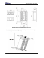
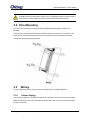
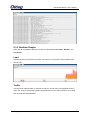
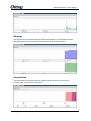
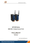
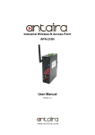
IAP-W420+/W422+ Series IEEE 802.11 b/g/n Access Point with User Manual Version 1.0 November, 2014 www.oring-networking.com IAP-W420+/W422+ Series User Manual COPYRIGHT NOTICE Copyright © 2014 ORing Industrial Networking Corp. All rights reserved. No part of this publication may be reproduced in any form without the prior written consent of ORing Industrial Networking Corp. TRADEMARKS is a registered trademark of ORing Industrial Networking Corp. All other trademarks belong to their respective owners. REGULATORY COMPLIANCE STATEMENT Product(s) associated with this publication complies/comply with all applicable regulations. Please refer to the Technical Specifications section for more details. WARRANTY ORing warrants that all ORing products are free from defects in material and workmanship for a specified warranty period from the invoice date (5 years for most products). ORing will repair or replace products found by ORing to be defective within this warranty period, with shipment expenses apportioned by ORing and the distributor. This warranty does not cover product modifications or repairs done by persons other than ORing-approved personnel, and this warranty does not apply to ORing products that are misused, abused, improperly installed, or damaged by accidents. Please refer to the Technical Specifications section for the actual warranty period(s) of the product(s) associated with this publication. DISCLAIMER Information in this publication is intended to be accurate. ORing shall not be responsible for its use or infringements on third-parties as a result of its use. There may occasionally be unintentional errors on this publication. ORing reserves the right to revise the contents of this publication without notice. CONTACT INFORMATION ORing Industrial Networking Corp. 3F., No.542-2, Zhongzheng Rd., Xindian Dist., New Taipei City 23148, Taiwan (R.O.C.) Tel: +886-2-2218-1066 // Fax: +886-2-2218-1014 Website: www.oring-networking.com Technical Support E-mail: [email protected] Sales Contact E-mail: [email protected] (Headquarters) [email protected] (China) ORing Industrial Networking Corp 1 IAP-W420+/W422+ Series User Manual Table of Content Getting Started .............................................................................................. 4 1.1 About the IAP-W420+/422+ Series .............................................................................. 4 1.2 Software Features ......................................................................................................... 4 1.3 Hardware Features ........................................................................................................ 4 Hardware Overview ....................................................................................... 6 2.1 Front Panel ..................................................................................................................... 6 2.1.1 Ports and Connectors ................................................................................................... 6 2.1.2 Front Panel LEDs ........................................................................................................ 6 2.2 Rear Panel ..................................................................................................................... 7 Hardware Installation .................................................................................... 8 3.1 Wall Mounting................................................................................................................. 8 3.2 Pole Mounting .............................................................................................................. 10 3.3 Wiring............................................................................................................................ 10 3.3.1 Power Supply ............................................................................................................ 10 3.3.2 Reset ......................................................................................................................... 11 Cables and Antenna .................................................................................... 12 4.1 Ethernet Pin Definition................................................................................................. 12 4.2 Wireless Antenna ......................................................................................................... 12 Management ................................................................................................ 13 5.1 Network Connection .................................................................................................... 13 5.2 Web Browser Management......................................................................................... 13 5.3 Status............................................................................................................................ 14 5.3.1 Overview ................................................................................................................... 14 5.3.2 System Log ................................................................................................................ 14 5.3.3 Realtime Graphs ........................................................................................................ 15 Load ........................................................................................................................................ 15 Traffic ..................................................................................................................................... 15 Wireless .................................................................................................................................. 16 Connections............................................................................................................................. 16 5.4 5.4.1 System .......................................................................................................................... 17 System Properties ...................................................................................................... 17 General Setting ........................................................................................................................ 17 ORing Industrial Networking Corp 2 IAP-W420+/W422+ Series User Manual Logging................................................................................................................................... 17 Time Synchronization .............................................................................................................. 18 5.4.2 Administration ........................................................................................................... 18 Router Password ...................................................................................................................... 18 5.4.3 Time Synchronization ................................................................................................ 18 5.4.4 Backup/Flash Firmware ............................................................................................. 19 Backup / Restore / Rest to default ............................................................................................ 19 5.4.5 Reboot ....................................................................................................................... 20 Flash new Firmware ................................................................................................................ 20 5.5 5.5.1 Network ........................................................................................................................ 20 Interfaces ................................................................................................................... 21 LAN ........................................................................................................................................ 21 Interface – LAN ...................................................................................................................... 22 5.5.2 Wifi ........................................................................................................................... 26 Associated Stations List ........................................................................................................... 34 5.5.3 Diagnostics ................................................................................................................ 34 Network Utilities ..................................................................................................................... 34 Technical Specifications ............................................................................ 36 Compliance.................................................................................................. 38 ORing Industrial Networking Corp 3 TGAP-W420+/W422+ Series User Manual Getting Started 1.1 About the IAP-W420+/422+ Series The IAP-W420+ / W422+ is a reliable IP-67 outdoor IEEE 802.11 b/g/n WLAN access point with two 10/100Base T(X) Ethernet ports. It can support AP/AP-Client/Client Mode modes and is specifically designed for the toughest industrial environments. With the combination of an IP-67 design and superb management functionality, the series provides a waterproof, dust-tight connection. In addition, IAP-W420+ provides a high power output of 500mw and throughput up to 80Mbps to satisfy long distance connections. The IAP-W422+ provides two N-type connectors for any N-type antennas to extend communication distances. You are able to configure the device by Web interface via the LAN port or by WLAN interface. In addition, the series provides a P.D port which is fully compliant with IEEE802.3af PoE standard to save the layout cost of power line. All in all, the series can be easily adopted in almost all kinds of applications and provides the most rugged solutions for managing your network in outdoors. 1.2 Software Features High speed air connectivity with support up to 300Mbps Highly secure transmission with WEP/WPA/WPA-PSK(TKIP,AES)/ WPA2/WPA2-PSK(TKIP,AES)/802.1X authentication supported High throughput over 80Mbps High power output of 500mw Long distance air connectivity up to 7 KM (IAP-W420+ only) Support X-Roaming < 100 ms Supports AP/AP-Client/Client modes Support MAC/IP/Port Filter Wireless connecting status monitoring Secured management by HTTPS Event warning via Syslog, e-mail, SNMP traps, and relay 1.3 Hardware Features 2 x 10/100Base-T(X) Ethernet ports in RJ45 connector type Build-in 10dBi antenna (IAP-W420+ only) Support external N-Type antenna installation (IAP-W422+ only) IP-67 waterproof housing Operating temperature: -25 to 70oC ORing Industrial Networking Corp 4 IAP-W420+/W422+ User Manual Storage temperature: -40 to 85oC Operating humidity: 5% to 95%, non-condensing Dimensions: 162(W) x 102(D) x 58(H) mm (6.38x 4.02x 2.28 inch.) (IAP-W420+) / 162(W) x 102(D) x 48(H) mm (6.38 x 4.02 x 1.89 inch.) (IAP-W422+) ORing Industrial Networking Corp 5 IAP-W420+/W422+ User Manual Hardware Overview 2.1 Front Panel 2.1.1 Ports and Connectors The devices are equipped with the following ports and features on the bottom panel. Port Description 10/100Base-T(X) 2 x 10/100Base-T(X) ports supporting auto-negotiation. One is Ethernet port PD port. Reset button To restore the device configurations back to the factory defaults, press the Reset button for a few seconds. Once the power indicator starts to flash, release the button. The device will then reboot and return to factory defaults. 1. Non-PoE LAN port 2. PoE LAN port 3. LNK/ACT LED for non-PoE LAN port 4. LNK/ACT LED for PoE LAN port 5. WiFi connections (weakest signal strength at the bottom, strongest at the top) 6. Power indicator 7. Reset button 2.1.2 Front Panel LEDs LED Color Status PWR Green On ETH Green normal function Port is linked Blinking Transmitting data Green Blinking ORing Industrial Networking Corp PoE power is on and power supply in On On WLAN Description WLAN activated (WLAN strength: 1<30%, 2<60%, 3<90%) Transmitting data via WLAN 6 IAP-W420+/W422+ User Manual 2.2 Rear Panel IAP-422+ 1. N-type antenna connectors ORing Industrial Networking Corp 7 IAP-W420+/W422+ User Manual Hardware Installation The device can be fixed to a pole or the wall using the supplied mounting kits. Before installing the device, make sure you have all of the package contents available and a PC with Microsoft Internet Explorer 6.0 or later, for using web-based system management tools. When installed outdoors, make sure the LAN ports are covered by RJ-45 rubber seals provided with the package. Do not remove the water-proof casing, and avoid touching or moving the device when the antennas are transmitting or receiving. When installing the device, make sure to keep the radiating at a minimum distance of 20 cm (7.9 inches) from all persons to minimize the potential for human contact during normal operation. Do not operate the device near unshielded blasting caps or in an otherwise explosive environment unless the device has been modified for such use by qualified personnel. 3.1 Wall Mounting IAP-W420+ Wall-mounting Measurements (Unit = mm) ORing Industrial Networking Corp 8 IAP-W420+/W422+ User Manual IAP-W422+ Wall-mounting Measurements (Unit = mm) To mount the device to the wall, simply insert a screw through the screw hole on the edge of the unit and tighten the screw for added stability. ORing Industrial Networking Corp 9 IAP-W420+/W422+ User Manual Instead of screwing the screws in all the way, it is advised to leave a space of about 2mm to allow room for sliding the device between the wall and the screws. 3.2 Pole Mounting You can mount the device to a pole using adjustable steel band straps included in the package. Thread the two supplied metal mounting straps through the screw holes on the edge of the unit and then put the straps around the pole, as shown below. Put the washers and nuts through the straps and tighten the strap. 3.3 Wiring For pin assignments of the power connector, please refer to the following tables. 3.3.1 Power Supply The device is powered by an Ethernet cable via the PoE port, which is on the right hand side. Make sure the PoE port is connected with an RJ-45 cable and check if the power LED lights up after connection. ORing Industrial Networking Corp 10 IAP-W420+/W422+ User Manual 3.3.2 Reset For protection, the reset button is placed in the case covered by a screw head. If you need to reset the device, remove the screw and use a very small point object like a needle or a toothpick to poke the reset button. To reboot the device, press the Reset button for 5 seconds. To restore the device configurations back to the factory defaults, press the Reset button for 3 seconds. ORing Industrial Networking Corp 11 IAP-W420+/W422+ User Manual Cables and Antenna 4.1 Ethernet Pin Definition The device provides two 10/100Base-T(X) Ethernet ports in RJ45 connector type. According to the link type, the AP uses CAT 3, 4, 5, 5e, UTP cables to connect to any other network device (PCs, servers, switches, routers, or hubs). Please refer to the following table for cable specifications and pin assignments. Cable Type Max. Length Connector 10Base-T Cat. 3, 4, 5 100-ohm UTP 100 m (328 ft) M12 or RJ45 100Base-T(X) Cat. 5 100-ohm UTP UTP 100 m (328 ft) M12 or RJ45 10/100Base-T(X) RJ-45 Port Pin Assignments Pin Number Assignment 1 TD+ 2 TD- 3 RD+ 4 N.C. 5 N.C. 6 RD- 7 N.C. 8 N.C. 4.2 Wireless Antenna The IAP-W422+ comes with two N-type WiFi antenna connectors. Attach the antenna to the connector by fastening the N-type male connector to the N-type female connector. Make sure both connectors are clean and dry. ORing Industrial Networking Corp 12 IAP-W420+/W422+ User Manual Management 5.1 Network Connection Before installing the device, you need to be able to access the device via a computer equipped with an Ethernet card or wireless LAN interface. To simplify the connection, it is recommended to use an Ethernet card to connect to a LAN. Follow the steps below to install and connect the device to PCs: Connect a computer to the device. Use either a straight-through Ethernet cable or cross-over cable to connect the LAN port of the device to a computer. Once the LED of the LAN port lights up, which indicates the connection is established, the computer will initiate a DHCP request to retrieve an IP address from the AP. 5.2 Web Browser Management An embedded HTML web site resides in the flash memory of the device. It contains advanced management features which you can manage from anywhere on the network through a standard web browser such as Microsoft Internet Explorer (Internet Explorer 5.0 or later versions). It is based on Java Applets which can reduce network bandwidth consumption, enhance access speed, and provide user-friendly viewing windows. Note: By default, IE5.0 or later version does not allow Java Applets to open sockets. You need to explicitly modify browser settings in order to enable Java Applets to use network ports. Open a web browser on your computer and type http://192.168.10.2 (default gateway IP of the ORing Industrial Networking Corp 13 IAP-W420+/W422+ User Manual device) in the address box to access the webpage. A login window will pop up where you can enter the default login name admin and password admin. For security reasons, we strongly recommend you to change the password. Click on Administrator > Password after logging in to change the password. 5.3 Status 5.3.1 Overview The overview screen will appear with general information of the device, including information regarding the system, memory, network, DHCP leases, wireless, and associated stations. 5.3.2 System Log The device will constantly log events and activities in System Log and provide the file for you to review. When you click on this tab, you can see the log of system messages. ORing Industrial Networking Corp 14 IAP-W420+/W422+ User Manual 5.3.3 Realtime Graphs Under the tab for Realtime Graphs, there are four tabs titled Load, Traffic, Wireless, and Connection. Load This tab will show the real-time CPU load of the device in chart which will be updated every few minutes. Traffic This tag shows network traffic in real time so that you can see how your bandwidth is being used. The incoming and outgoing traffic is represented on a line chart in different color, along with average and peak utilization. ORing Industrial Networking Corp 15 IAP-W420+/W422+ User Manual Wireless This tag will show the real-time status of wireless transmission in chart including wireless signal transmission and noises as well as the physical layer transmission rate. Connections This tag will show the real-time status of existing network connections of the device, including UDP, TCP, and other connections. ORing Industrial Networking Corp 16 IAP-W420+/W422+ User Manual 5.4 System This section is about the System top-level tab. 5.4.1 System Properties General Setting This tab allows you to do general settings for the device including the host name and the time zone where the device is located in. You can use the local time of the browser time zone by clicking Sync with browser. Label Description Local Time Displays the local time according to the Timezone. Hostname Input a name for the device to be its hostname. Timezone Choose a timezone for the device from the drop-down list. Logging Specifies parameters used for the system log, such as System log buffer size, External system log server, External system log server port, Log output level, and Cron Log Level. Label Description System log buffer size Specify a log buffer size in KB. External system log sever Input the IP address of the external system log server you want to use. Log output level The log output level controls the level of debug output that will be output. Choose a level from the drop-down list. Available options include Debug, Info, Notice, Warning, Error, Critical, Alert, and Emergency. Cron log level Select a value from the drop-down list. Debug: Verbose messages to aid in troubleshooting; ORing Industrial Networking Corp 17 IAP-W420+/W422+ User Manual detailed messages, normal messages, warnings, and errors are logged. Normal: Common administrative messages of the server, warnings, and errors are logged. Warning: Problems that require attention and errors are logged. Time Synchronization The Network Time Protocol (NTP) synchronizes the clocks of computer systems across the Internet. A correct date and time will help the system log events. To synchronize the computer clock of the device with the clock of an NTP server, you need to configure the NTP settings. Label Description Enable NTP client Obtains the date and time from specified Network Time Protocol (NTP) servers. Provide NTP server Check this box will turn the device into a local NTP server. NTP server candidates These are the sources of the time information. You can add new servers by clicking add button at the end of server hostname field. 5.4.2 Administration Router Password This page allows you to set up a password for the device. You need to type in the password twice in the following fields. 5.4.3 Time Synchronization This page enables you to configure system time update settings. You can set up update intervals and the time server you want to use. ORing Industrial Networking Corp 18 IAP-W420+/W422+ User Manual General Label Description Current system time Shows the current time of the device Update intervals (in Specify an interval for time synchronization. The seconds) synchronization protocol will adjust the clock according to the specified interval. Count of time Number of time measurements to perform before exiting. 0 measurements means to never stop. Clock Adjustment Label Description Offset frequency Specify the offset frequency for the clock Time Servers Label Description Hostname Enter the hostname of the time server you want to use. Port Enter the port of the time server you want to connect to. 5.4.4 Backup/Flash Firmware Backup / Restore / Rest to default This page allows you to save existing configurations as a backup file or return the device to previous settings. ORing Industrial Networking Corp 19 IAP-W420+/W422+ User Manual Label Description Download backup Reset to defaults Click Generate archive to save the current system settings as a file stored in the local hard drive. Click Perform reset to reset the device to the factory settings. The device will reboot to validate the default settings. Restore backup You can restore configurations to previous status by installing a previous configuration file. To do this, click on Browse to locate the file you want to upload in the local hard drive and click Upload archive. 5.4.5 Reboot This page allows you to reboot the operating system of your device. This is similar to the power-off and power-on cycle. The system configuration remains the same. Any changes that are not applied are lost. Flash new Firmware ORing launches new firmware constantly to enhance performance and functions. To upgrade firmware, download new firmware from ORing’s website to your PC and install it via Web upgrade. Make sure the firmware file matches the model of your device. It will take several minutes to upload and update the firmware. After upgrade completes successfully, reboot the device. If you want to preserve network settings after updating, check the Keep settings box. 5.5 Network This section allows you to set up network configurations for your device, including LAN and Wifi settings. Interfaces tab shows an overview of the network interfaces. You can view and ORing Industrial Networking Corp 20 IAP-W420+/W422+ User Manual configure the interfaces of the local area network (LAN) zone as well as the wide area network (WAN) zone. Network address translation (NAT) occurs between these two network zones. The router that performs the NAT is called a gateway. A gateway is a network point that acts as an entrance to another network. 5.5.1 Interfaces LAN The LAN zone (icon with two Ethernet ports) has the bridged interface “br-lan” which consists of one physical port (icon with one Ethernet port) and two wireless networks (each icon looking like a short standing fan) on the device. You can edit existing interfaces or add new interfaces in this page. Label Description Status Shows network information of the device including interface IP, uptime, MAC address, TX/RX counters, and IPv4 setting. Action You can perform different actions in this section. Connect: Reconnect this interface Stop: Shutdown this interface Edit: Edit this interface Clicking Add new interfaces will bring up the following window. After filling out the required field, press Submit button to save new interface. Label Description Name of the new Specify a name for the new interface ORing Industrial Networking Corp 21 IAP-W420+/W422+ User Manual interface Protocol of the new Choose a protocol for the new interface. Available values include: interface Static address: static configuration with fixed address and netmask DHCP client: address and netmask are assigned by DHCP Unmanaged: unspecified protocol Relay bridge: use the protocol of relay bridge Create a bridge over This checkbox enables a bridge over multiple interfaces. multiple interfaces Cover the following Choose which interfaces to be covered from (Ethernet interface Adapter: eth0, eth1, Master ORing and Custom Interface). Clicking Edit will bring you to the following interface. Interface – LAN Common Configuration This section provides several configuration tags. This configuration file is responsible for defining switch VLANs, interface configurations and network routes. Below is an overview of the section types that may be defined in the network configuration. A minimal network configuration for a router usually consists of at least two interfaces (lan and wan) and a switch section if applicable. Any change in the Network Configuration requires a Save and Apply in order for the changes to be applied to the system. Once the "Save & Apply" button is clicked, the system will save the current configuration automatically. General Setup Label Description Status Shows a summary of the current LAN port status, which includes uptime, MAC address, received bytes and packets, transmitted ORing Industrial Networking Corp 22 IAP-W420+/W422+ User Manual bytes and packets, and IPv4 address. Protocol This specifies the interface protocol. Static address is necessary if other devices obtain internet connection through this device. The interface protocol may be one of the following: Static address: static configuration with fixed address and netmask DHCP client: address and netmask are assigned by DHCP Unmanaged: unspecified protocol, PPP - PPP protocol - dialup modem connections PPtP: connection via PPtP VPN PPPoE: PPP over Ethernet - DSL broadband connection, PPPoATM: PPP over ATM - DSL connection using a built in modem UMTS/GPRS/EV-DO: protocol 3G, CDMA, UMTS or GPRS connection using an AT-style 3G modem, L2TP: Layer 2 Tunneling protocol. Default is specified as Static address. IPv4 address Sets the IP address of the device (e.g. 192.168.21.1), where you can access the router's configuration web page. IPv4 netmask Sets the subnet mask e.g. 255.255.255.0. The IP address and netmask together determine the subnet or network ID (e.g. 192.168.21.0/24). Two devices must be in the same subnet in order to establish a (Layer 2) link between them. IPv4 gateway Specifies the IP address of the remote router that allows the device's shell to gain internet access. IPv4 broadcast Specifies the IPv4 broadcast address, optional. Use custom DNS Configures the IP address of the DNS servers. The computers in servers the same subnet as this device can then set this device's IP address as their preferred DNS server to obtain the same DNS service. Advanced Setting The following are options in the Advanced Settings section tab. Some of these options are shown, depending on the protocol being used. ORing Industrial Networking Corp 23 IAP-W420+/W422+ User Manual Label Description Bring up on boot Check the box to make sure that your new swap space is activated while booting up computer Override MAC Allows you to specify a different MAC address other than the address router's original MAC address. This is useful if the ISP uses the MAC address of a router to identify a customer. Suppose that the router needs to be replaced. The new router can take on the MAC address of the previous router in order to continue having internet access. Override MTU Sets the maximum transmission unit (MTU), the default being 1500 bytes. Unless, your ISP requires, it is not recommended to change this setting. Use gateway metric Allows you to specify a gateway metric. This acts as a cost for choosing the gateway when a connected device has to select between multiple available gateways. The gateway with the smallest metric is chosen. Physical Setting Label Description Bridge interfaces Check to create a bridge over specified interface Enable STP Enables the Spanning Tree Protocol on this bridge. It is unchecked by default. Interface Chooses which physical interface to use for the WAN zone. This can be the Ethernet Adapter“eth0” or “eth1” that corresponds to each of the two ports on the device for example. It could also be ORing Industrial Networking Corp 24 IAP-W420+/W422+ User Manual set as the Wireless Network. If no Interface is selected, all interfaces would be within the LAN zone. Firewall Setting Label Description Create/Assign This field chooses the firewall zone you want to assign to this firewall-zone interface. Select unspecified to remove the interface from the associated zone or fill out the create field to define a new zone and attach the interface to it. The default is set to lan. DHCP Server The Dynamic Host Configuration Protocol (DHCP) is a standardized networking protocol used by servers on an IP network to allocate IP addresses automatically to client devices. It is recommended to enable the DHCP server because network address translation (NAT) occurs between the WAN zone and the LAN zone. Devices or computers that connect to this hotspot router can then obtain their IP addresses automatically. In addition, the default gateway IP address and the DNS server IP address are automatically configured for these connected devices. If the DHCP server is left disabled, it is still possible for devices to connect to the hotspot. Each device would need a unique static IP address on the same subnet as this hotspot router. Set the default gateway and DNS server for the device both to be the IP address of this hotspot router. General Setup Label Description Ignore interface Disables DHCP for this interface. You should uncheck this to enable DHCP. Start Specifies the lowest leased address as offset from the network ORing Industrial Networking Corp 25 IAP-W420+/W422+ User Manual address, the default being 100. Limit Sets the maximum number of leased addresses, the default being 150. Leasetime States the expiry time of leased addresses, the default being 12h. Advanced Settings Label Description Dynamic DHCP Dynamically allocates DHCP addresses for clients. If disabled, only clients having static leases will be served. Checked by default. Force Forces DHCP on this network even if another server is detected, unchecked by default. IPv4-Netmask Overrides the netmask sent to clients. Normally it is calculated from the subnet that is served. DHCP-Options Defines additional DHCP options, for example "6,192.168.2.1,192.168.2.2" which advertises different DNS servers to clients. Normally, connected devices would take this board's IP address as the default gateway. To set an alternative default gateway, add the DHCP option "3,192.168.2.3" for example. 5.5.2 Wifi This section contains the section tabs for General Setup, Wireless Security, MAC-Filter, and Advanced Settings. ORing Industrial Networking Corp 26 IAP-W420+/W422+ User Manual Wireless Option This section contains the section tabs for General Setup, Wireless Security, MAC-Filter, and Advanced Settings. The options will vary with the wireless mode you use. Wireless Mode Access Point Mode This mode can be connected to Station mode and forwards all traffic to the network devices connected to the Ethernet devices of the Station. Label Description SSID-AP Fill in the interface SSID. This will display the name of the wireless network that this access point (AP) is offering. Pre-share Key - AP Fill in the KEY value (Default is WPA2+AES. you can change to other option after interface is built) Station/Client This is a client mode that can be connected to the Access Point mode. It is used to bridge the wireless connection to an Access Point. It forwards all the traffic to and from network devices to the Ethernet interface. This mode translates all the packets that pass through the device to its own MAC address, resulting in a lack of transparency. Interface as Client function ORing Industrial Networking Corp 27 IAP-W420+/W422+ User Manual Label Description SSID – Station This will display the name of the wireless network that this station should be associated with. BSSID - Station This is the MAC address of the AP's radio. Encryption Chose an encryption method among the following options: Open, WEP Open System, WEP Shared Key, WPA-PSK, WPA2-PSK, and WPA-PSK/WPA2-PSK Mixed Mode. Wired Equivalent Privacy (WEP) is the oldest and least secure encryption algorithm. Stronger encryption using WPA or WPA2 should be used where possible. For the WEP Open System and WEP Shared Key encryptions, you can specify up to 4 keys and only 1 would be used at a time. Wifi protected access (WPA) is a stronger encryption than WEP. Furthermore, WPA2 was developed to strengthen the security of WPA and is stronger than WPA and WEP. You can also click the Scan button next to the SSID field and have the information to be filled in automatically. When clicking Scan button, the following window will appear for you to join the network. A list of available nearby wireless networks will be displayed. Click on Join Network will bring up the following window. This page will associate this device with the selected wireless network. Un-check the Replace Wireless Configuration and enter the connection details for the network you selected. If desired you can name the new network configuration, and assign the connection to a specific firewall zone. ORing Industrial Networking Corp 28 IAP-W420+/W422+ User Manual AP – Client Label Description SSID – AP Fill in the interface SSID. This will display the name of the wireless network that this access point (AP) is offering. Pre-share Key - AP Fill in the KEY value (Default is WPA2+AES. you can change to other option after interface is built) SSID – Station This will display the name of the wireless network that this station should be associated with. BSSID - Station This is the MAC address of the AP's radio. Encryption Chose an encryption method among the following options: Open, WEP Open System, WEP Shared Key, WPA-PSK, WPA2-PSK, and WPA-PSK/WPA2-PSK Mixed Mode. Wired Equivalent Privacy (WEP) is the oldest and least secure encryption algorithm. Stronger encryption using WPA or WPA2 should be used where possible. For the WEP Open System and WEP Shared Key encryptions, you can specify up to 4 keys and only 1 would be used at a time. Wifi protected access (WPA) is a stronger encryption than WEP. Furthermore, WPA2 was developed to strengthen the security of WPA and is stronger than WPA and WEP. Wireless Overview This page shows the status of the available wireless networks. You can use the Scan button to scan for available wireless networks. This button is available if the device is operating as a Station. You can then select the network to connect to. You can also click on Enable to enable the wireless network or click on Edit to modify network settings. ORing Industrial Networking Corp 29 IAP-W420+/W422+ User Manual Add/ Edit Clicking on the Edit button for a network would bring you to the configuration page. This page contains the sections Device Configuration and Interface Configuration. The Device Configuration section covers the physical settings of the hardware such as channel, transmit power, or antenna selection. These are shared among all defined wireless networks of the radio. Per network settings like encryption or operation mode are grouped in the Interface Configuration. Label Description Wireless network is Click on Disable will disable the wireless network. enabled Channel Chooses the frequency channel. The default setting of Auto may be used. For an AP, it would select the channel with the least interference from other APs. For a station, it would automatically select the same channel as its AP. The frequency channel may also be manually selected. An AP and its station must have the same channel in order to communicate. Transmit Power Chooses the transmit power of the radio. This is the total power supplied to the antennas of the radio. The maximum power also depends on the frequency channel used. ORing Industrial Networking Corp 30 IAP-W420+/W422+ User Manual Label Description Mode Chooses the wireless standard used. 802.11g is an older standard while 802.11n is a newer standard that offers higher data rates. The choice of 802.11g+n is a combination of 802.11g and 802.11n, and operates in the 2.4 GHz frequency band. HT Mode Allows the network to use both 20 MHz and 40 MHz bands. Required on AP side primarily to support co-existence. The station can also send intolerant bit status to AP to signal use of 20 MHz channel. The station will follow the AP's channel bonding and channel switching HT 20/40 mechanism. Disabling this setting forces the use of 40 MHz bandwidth/channel bonding, and results in high data rate. Country Code Selects the country. Each country has its own transmit power and frequency regulations. To ensure regulatory compliance, you must select the country where the device is operating in. The transmit power levels for each channel are tuned accordingly. Distance Specifies the distance between the AP and the station. Min is 300 Optimization meters and Max is 12000 (80MHz), 24000 (40MHz), 48000 (20MHz). This value may be set to slightly more than the physical distance between the AP and the farthest station. Fragmentation Specifies the maximum size for a packet before data is Threshold fragmented into multiple packets. The range is 256-2346 bytes, or “off”. Setting the Fragmentation Threshold too low may result in poor network performance. The use of fragmentation can increase the reliability of frame transmissions. Because smaller frames are sent, collisions are much less likely to occur. However lower values of the Fragmentation Threshold will result lower throughput as well. Little or no modification of the Fragmentation Threshold value is recommended as the default setting of 2346 is optimum for most wireless networks. RTS/CTS Threshold Determines the packet size of a transmission and, through the use of an access point, helps control traffic flow. The range is 0-2347bytes, or "off". The default value is 2347, which means that RTS is disabled. RTS/CTS (Request to Send / Clear to Send) is the mechanism used by the 802.11 wireless networking protocol to reduce frame collisions introduced by the hidden terminal problem. RTS/CTS packet size threshold is 0-2347 bytes. If the packet size ORing Industrial Networking Corp 31 IAP-W420+/W422+ User Manual the node wants to transmit is larger than the threshold, the RTS/CTS handshake gets triggered. If the packet size is equal to or less than threshold the data frame gets sent immediately. System uses Request to Send/Clear to Send frames for the handshake which provide collision reduction for access point with hidden stations. The stations are sending an RTS frame first while data is sent only after handshake with an AP is completed. Stations respond with the CTS frame to the RTS, which provides clear media for the requesting station to send the data. CTS collision control management has time interval defined during which all the other stations hold off the transmission and wait until the requesting station will finish transmission. Label Description Mode Selects whether the device is operating as an Access Point (AP) or a Station. Other options are Access Point WDS and Station WDS. ESSID Specifies the name or extended service set identifier (ESSID) of the wireless network as it is provided in the beacon message. The network name can be up to 32 characters in length and can contain spaces. When running in AP mode, it is the name of the network as advertised in the beacon message. In Station mode, it is the network name that the station associates with. Hide ESSID Hides the network name (ESSID) from being broadcast publicly. (This option is for a device operating as an AP.) WMM Mode Provides Quality of Service (QoS) features, checked by default. Wireless multimedia enables the classification of the network traffic into 4 main types, voice, video, best effort, and background, in decreasing order of priority. Higher priority traffic has a higher transmission opportunity and would have to wait less time to transmit. As a result, an existing video stream would not be interrupted by additional background processes. ORing Industrial Networking Corp 32 IAP-W420+/W422+ User Manual Label Description Encryption Choose an encryption method from the drop-down list. Wired Equivalent Privacy (WEP) is the oldest and least secure encryption algorithm. Stronger encryption using WPA or WPA2 should be used where possible. For the WEP Open System and WEP Shared Key encryptions, you can specify up to 4 keys and only 1 would be used at a time. Used Key Slot: Chooses between Key #1 to Key #4. Key 1 ~ Key 4: Specifies a string of characters to be used as the password. It may consist of 5 ASCII characters or 10 HEX characters, implying a 64-bit WEP key length. Otherwise, it may consist of 13 ASCII or 26 HEX characters, implying a 128-bit key length. Wifi protected access (WPA) is a stronger encryption than WEP. Furthermore, WPA2 was developed to strengthen the security of WPA and is stronger than WPA and WEP. Cipher: Can be set to CCMP (AES), TKIP, or TKIP and CCMP (AES). The Temporal Key Integrity Protocol (TKIP) was developed as a temporary replacement for WEP. The Counter Mode Cipher Block Chaining Message Authentication Code Protocol (CCMP) is based on the Advanced Encryption Standard (AES) and is the most secure protocol. Key: The pre-shared key (PSK) is the password for the wireless network. This may consist of 8 to 63 ASCII characters. This section tab is only available for a device operating as an AP. ORing Industrial Networking Corp 33 IAP-W420+/W422+ User Manual Label Description MAC-Address Filter Allows only devices with the listed MAC address to associate with this AP, or lets you block devices with the listed MAC address. MAC-List Adds the MAC address of the remote device to either block or allow. Associated Stations List This section shows the connected devices, if the router is in the AP mode. Label Description SSID Displays the name of the wireless network that this station should be associated with. MAC Address Displays the MAC address of the station's radio. IPv4-Address Shows the IP address of the device as seen from the WAN zone. Signal Displays the received signal strength from the station. Noise Displays the received noise power at the AP. RX Rate Shows the transmit bit rate from the AP towards this station. TX Rate Shows the receive bit rate at the AP from this station. 5.5.3 Diagnostics Network Utilities This page provides several network utility tools for diagnosing the cause of network or hardware errors such as ping, traceroute, and nslookup. Ping A simple ping of the server checks to see if it’s responding. If there are serious server problems, a ping will either time out, or run very slowly. If you are able to find the server via DNS, but can’t get a ping response from it, this would point to an error with either the physical server, or a fault in the network that connects the client and server. ORing Industrial Networking Corp 34 IAP-W420+/W422+ User Manual Traceroute Traceroute will try to follow the path that connects the client and server. In the case where the client can find but is unable to connect to your server, the Traceroute will help locate the cause of the error. This test is useful for identifying when specific data centers or CDN locations are having issues. Note: Traceroute is an imperfect test because many nodes in the network will not respond to the trace route calls, and those nodes will show as timeouts. Nslookup Nslookup will identify where the URL for the server points to. This command will check to determine what IP address the name server is pointing to for your URL. This tool will help identify if the name servers encounters conflicts, propagation errors, or specific locations that have trouble finding the server. ORing Industrial Networking Corp 35 IAP-W420+/W422+ User Manual Technical Specifications ORing WLAN Access Point IAP-W420+ Model IAP-W422+ Physical Ports 10/100 Base-T(X) Ports in RJ45 2(one port with PoE) Auto MDI/MDIX WLAN interface Operating Mode AP/Bridge/AP-Client/Client Antenna Connector Build-in 10dBi panel antenna Radio Frequency Type OFDM Modulation Frequency Band 2 x External N-type antenna connector IEEE802.11b: CCK, DQPSK, DBPSK IEEE802.11g/n: OFDM with BPSK, QPSK, 16QAM, 64QAM America / FCC : 2.412~2.462 GHz (11 channels ) Europe CE / ETSI: 2.412~2.472 GHz ( 13 channels ) IEEE802.11b: 11, 5.5, 2, 1 Mbps; Transmission Rate IEEE 802.11g: 54, 48, 36, 24, 18, 12, 9, 6 Mbps IEEE 802.11n: up to 300Mbps Transmit Power 800mw Max. Receiver Sensitivity -96dBi ± 2dBi WEP: (64-bit ,128-bit key supported) WPA/WPA2 :802.11i(WEP and AES encryption) Encryption Security WPAPSK (256-bit key pre-shared key supported) 802.1X Authentication supported TKIP encryption Wireless Security SSID broadcast disable Protocol Support Protocol ARP,BOOTP, DHCP, DNS, HTTPs, IP, ICMP, SNTP, TCP, UDP, RADIUS, SNMP, STP (IEEE 802.1D) LED indicators Power indicator 10/100Base-T(X) RJ45 port indicator WLAN LED 1 x LED, Green On: Power(PoE) is on and functioning Normally. 2 x LED, Green On: Port Link / Act, Blinking: data transmission 3 x LED, Green for WLAN Strength: 1<30%, 2<60%, 3<90% Power Input power 48VDC from P.o.E Power consumption (Typ.) 9watts Physical Characteristic Enclosure Dimension (W x D x H) Weight (g) IP-67 162(W)x 102(D)x 58(H) mm 162(W)x 102(D)x 48(H) mm (6.38x 4.02x 2.28 inch.) (6.38x 4.02x 1.89 inch.) 720 g 790 g Environmental Storage Temperature -30 to 85oC (-22 to 185oF) Operating Temperature -20 to 70oC (-4 to 158oF) Operating Humidity 100% Non-condensing Regulatory approvals EMI FCC Part 15, CISPR (EN55022) class A EN61000-4-2 (ESD), EN61000-4-3 (RS), EN61000-4-4 (EFT), EN61000-4-5 (Surge), EN61000-4-6 (CS), EMS EN61000-4-8, EN61000-4-11 Shock IEC60068-2-27 ORing Industrial Networking Corp 36 IAP-W420+/W422+ User Manual Free Fall IEC60068-2-32 Vibration IEC60068-2-6 Safety EN60950-1 Warranty 3 years ORing Industrial Networking Corp 37 IAP-W420+/W422+ User Manual Compliance FCC Statement This device complies with Part 15 of the FCC Rules. Operation is subject to the following two conditions: (1) This device may not cause harmful interference and (2) this device must accept any interference received, including interference that may cause undesired operation. RF exposure warning: The equipment complies with RF exposure limits set forth for an uncontrolled environment. The antenna(s) used for this transmitter must not be co-located or operating in conjunction with any other antenna or transmitter. You are cautioned that changes or modifications not expressly approved by the party responsible for compliance could void your authority to operate the equipment. This device should be operated with minimum distance 20cm between the device and all persons. Operations in the 5.15-5.25GHz band are restricted to indoor usage only. Industry Canada Statement This device complies with Industry Canada licence-exempt RSS standard(s). Operation is subject to the following two conditions: (1) this device may not cause interference, and (2) this device must accept any interference, including interference that may cause undesired operation of the device. Le présent appareil est conforme aux CNR d'Industrie Canada applicables aux appareils radio exempts de licence. L'exploitation est autorisée aux deux conditions suivantes : (1) l'appareil ne doit pas produire de brouillage, et (2) l'utilisateur de l'appareil doit accepter tout brouillage radioélectrique subi, même si le brouillage est susceptible d'en compromettre le fonctionnement. Industry Canada - Class B This digital apparatus does not exceed the Class B limits for radio noise emissions from digital apparatus as set out in the interference-causing equipment standard entitled “Digital Apparatus,” ICES-003 of Industry Canada. Cet appareil numérique respecte les limites de bruits radioélectriques applicables aux appareils numériques de Classe B prescrites dans la norme sur le matérial brouilleur: “Appareils Numériques,” NMB-003 édictée par l’Industrie. ORing Industrial Networking Corp 38 IAP-W420+/W422+ User Manual Operation is subject to the following two conditions: (1) this device may not cause interference, and (2) this device must accept any interference, including interference that may cause undesired operation of the device. L'opération est soumise aux deux conditions suivantes: (1) cet appareil ne peut causer d'interférences,et (2) cet appareil doit accepter toute interférence, y compris celles susceptibles de provoquer fonctionnement du dispositif. To reduce potential radio interference to other users, the antenna type and its gain should be so chosen that the equivalent isotropically radiated power (e.i.r.p.) is not more than that permitted for successful communication. Afin de réduire les interférences radio potentielles pour les autres utilisateurs, le type d'antenne et son gain doivent être choisie que la puissance isotrope rayonnée équivalente (PIRE) est pas plus que celle premise pour une communication réussie RF exposure warning: The equipment complies with RF exposure limits set forth for an uncontrolled environment. The antenna(s) used for this transmitter must not be co-located or operating in conjunction with any other antenna or transmitter. Avertissement d'exposition RF: L'équipement est conforme aux limites d'exposition aux RF établies pour un incontrôlés environnement. L'antenne (s) utilisée pour ce transmetteur ne doit pas être co-localisés ou fonctionner en conjonction avec toute autre antenne ou transmetteur. ORing Industrial Networking Corp 39