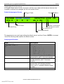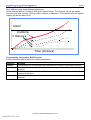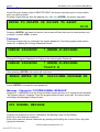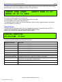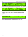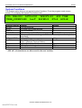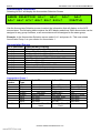
1
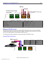
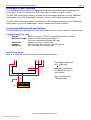
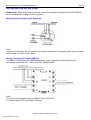
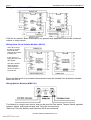
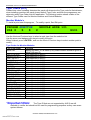
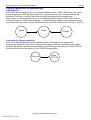
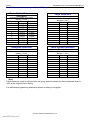
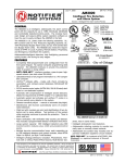
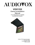
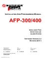
INSTALLATION AND PROGRAMMING MANUAL
AFP-300/400
INTELLIGENT FIRE
DETECTION AND
ALARM SYSTEM
SOFTWARE VERSION 2.2
REVISION AUS 3
NSW (Head Office)
7 Columbia Court
Norwest Business Park
Baulkham Hills NSW 2153
QLD
16 Lucy St
Moorooka
Qld 4104
VIC
Unit 2 297 Ingles St
Port Melbourne
Vic 3207
Ph:
Fax:
Ph:
Fax:
Ph:
Fax:
(02) 9899-4155
(02) 9899-4156
Notifier Inertia Pty Ltd (A.C.N 002 692 962)
A PITTWAY COMPANY
www.inertia.com.au
www.PDF-Zoo.com
(07) 3892-6444
(07) 3892-6455
(03) 9681-9929
(03) 9681-9930
PAGE 2
AFP 300/400 INSTALLATION AND PROGRAMMING MANUAL
Installation ........................................................................................................................... 4
OVERVIEW ...................................................................................................................................... 4
Passwords.................................................................................................................................................. 4
Operating Features .................................................................................................................................... 4
Basic System Requirements (SPECS) ...................................................................................................... 5
AFP-400 System Diagram .....................................................................................................................................5
AFP-300/400 Basic termination points. ................................................................................................................5
Panel Primary requirements
6
Compatible System Components: ............................................................................................................. 6
Compatible Annunciators........................................................................................................................... 7
Initial Installation Tasks.............................................................................................................................. 7
The Power Supply Connections
8
240Vac- 24Vdc (Resettable/Non resettable) and Battery Connections..................................................... 8
AFP-300/400 Power Supply ..................................................................................................................................8
MPS-400 Battery Charger Supervision .................................................................................................................8
Output Relays (on the power Supply) ........................................................................................................ 9
Alarm and Fault Relays (on the Power Supply) ......................................................................................... 9
RS-232 and RS-485 Circuits
10
Wiring for RS-485 Annunciator Circuits ..................................................................................................... 10
Terminal & ACS Circuits (RS-485) .......................................................................................................................10
RS-485 Terminal & ACS Connectors ....................................................................................................................11
Wiring for RS-232 Circuits ......................................................................................................................... 11
Remote Printer Connections..................................................................................................................................11
Remote Terminal Connections...............................................................................................................................12
Connecting A Laptop in Terminal Mode to Emulate A Printer ................................................................... 12
Connecting a Laptop VIA Verifier 400 to program the Panel..................................................................... 12
Analogue Loop Overview
13
Loop wiring Methods and specification ...................................................................................................... 13
Communication SLC Loop.....................................................................................................................................13
Style 4 Loop Wiring ...............................................................................................................................................13
Style 6 Loop Wiring ...............................................................................................................................................14
Style 7 Loop Wiring ...............................................................................................................................................14
Wiring devices on the Loop
15
Wiring Analogue Addressable Detectors...............................................................................................................15
Wiring Conventional Circuits (MMX-2)................................................................................................................15
Wiring Control Modules (CMX-2).........................................................................................................................16
Wiring Short Circuit Isolator Modules (ISO-X) ....................................................................................................16
Wiring Monitor Modules (MMX-101) ...................................................................................................................16
XP-5M & XP-5C Modules .....................................................................................................................................17
Common fault finding techniques
18
Shield Termination ................................................................................................................................................18
Before connecting the loop ........................................................................................................................ 18
The Affects of Capacitance on Ground Faults.......................................................................................................19
COPYRIGHT © 2000, NOTIFIER INERTIA PTY LTD
www.PDF-Zoo.com
AFP 300/400 INSTALLATION AND PROGRAMMING MANUAL
PAGE 3
Programming ....................................................................................................................... 20
OVERVIEW ...................................................................................................................................... 20
Turning the Panel on for the first Time
20
How to enter a ‘Default’ Program............................................................................................................... 20
Program Mode Screen ............................................................................................................................... 21
Clear Program............................................................................................................................................ 21
Autoprogram .............................................................................................................................................. 21
Duplicate (Dual) Addressing.................................................................................................................................22
Default Autoprogram Screen.................................................................................................................................23
Autoprogram Defaults ...........................................................................................................................................23
Autoprogram- Device no longer needed .................................................................................................... 24
Installing a Device ...................................................................................................................................... 24
Edit a Point................................................................................................................................................. 24
Modifying a Point........................................................................................................................................ 24
Editing Multi Detector Mode....................................................................................................................... 25
Programming Cooperative Multi-Detector ...........................................................................................................25
Delete a Point............................................................................................................................................. 26
Password ................................................................................................................................................... 26
Message - Change the “SYSTEM NORMAL MESSAGE” ......................................................................... 26
Zone Labels ............................................................................................................................................... 27
Special Zones ............................................................................................................................................ 27
F5-F6 (TIME CONTROL) .....................................................................................................................................28
F7 (Holiday) ..........................................................................................................................................................28
System Functions
29
Annunciator selection
30
Annunciator Groups ................................................................................................................................... 30
Annunciator Group 1.............................................................................................................................................30
Annunciator Group 2.............................................................................................................................................31
Annunciator Group 3-5 .........................................................................................................................................31
Annunciator Group 6 – 8.......................................................................................................................................31
System Check Function ............................................................................................................................. 32
Status Change
32
Isolate a Device or Zone ............................................................................................................................ 33
Change Sensitivity ..................................................................................................................................... 33
Clear Verification Counters ........................................................................................................................ 33
Clear History .............................................................................................................................................. 34
Time and Date............................................................................................................................................ 34
Walk Test ................................................................................................................................................... 34
Type Codes (ID’s)
35
Monitor Module’s........................................................................................................................................ 35
Type Codes for Monitor Modules ..........................................................................................................................35
Control Module’s ........................................................................................................................................ 36
Type Codes for Control Modules...........................................................................................................................36
Panel’s Monitored Output Circuits ............................................................................................................. 36
Control-By-Event Programming
37
CBE Equation........................................................................................................................................................37
Automatically Change sensitivity ..........................................................................................................................37
Nominal Detector Sensitivity
38
Self Optimising Pre-Alarm ....................................................................................................................................38
Sensitivity Levels for the AFP-400: (Graph)............................................................................................... 39
Sensitivity Levels- Autoprogram Default Tables: ..................................................................................................40
COPYRIGHT © 2000, NOTIFIER INERTIA PTY LTD
www.PDF-Zoo.com
PAGE 4
AFP 300/400 INSTALLATION AND PROGRAMMING MANUAL
Installation
Overview
The AFP-400 is a modular, intelligent Fire Alarm Control Panel (FACP) with an extensive list of
powerful features. The CPU module, power supply module, and cabinet combine to create a
complete fire control system for most applications such as commercial, residential and industrial
buildings. Optional modules mount to the chassis to provide additional output circuits.
Unlike conventional fire control panels, the AFP-300/400 intelligently communicates with each
detector and Input/Output module on the entire system. Thus providing accurate information as
to the exact point of alarm and the ability to operate specific outputs using programmable logic
functions. The method of communication with field devices is a high-speed proprietary protocol
capable of supporting up to 99 detectors and 99 modules per two-wire loop.
The AFP-300 panel is capable of 1 loop and the AFP-400 is capable of 2 loops. Each of the
panels can also accommodate up to 10 Annunciators, each can provide 32 x fully
programmable LED indications, 16 x single pushbutton functions, 8 x relay outputs, remote LCD
displays etc.
These systems due to their immense flexibility require a firm understanding of the total
operation of the system for their correct operation. Please ensure that the following document is
read in its entirety before making any attempt to operate the system.
Passwords
As the program in the system is critical to the correct operation during fire alarm conditions, it is
protected from modification by a five-digit password. All other features are available without
password protection.
Please ensure the password is recorded and stored in a safe place as it remains unique and
your key to future system modification.
Operating Features
Alarm Verification selection per point, with tally.
Silence Inhibit timer and Auto Silence timer.
Automatic time-of-day and day-of-week controls functions, with holiday option.
User-defined password and key-protected nonvolatile memory.
AWACS (Advanced Warning Addressable Combustion Sensing) with nine field-adjustable PreAlarm levels with programmable Control-by-Event (CBE)
Operate automatic smoke or heat detector sounder base on action Pre-Alarm level, with general
evacuation on alarm level.
Programmable Control-by-Event control of outputs from individual alarm addressable devices.
COPYRIGHT © 2000, NOTIFIER INERTIA PTY LTD
www.PDF-Zoo.com
AFP 300/400 INSTALLATION AND PROGRAMMING MANUAL
PAGE 5
Basic System Requirements (SPECS)
The following section covers the suggested installation methods for the AFP-300/400.
These are typical installation methods, and may not cover everything needed, Contact the
Manufacturer for any additional information or assistance needed.
AFP-400 System Diagram
Loop 1
FI
Loop 2
FI
RS-485(Term)
RS-485(ACS)
PC
NCS
Graphics
Optional
Printer
AFP-300/400 Basic termination points.
Terminal Mode. RS-485
RS-485
PC Term
Printer.
COPYRIGHT © 2000, NOTIFIER INERTIA PTY LTD
www.PDF-Zoo.com
ACS Mode
.
SLC Loop 1
SLC Loop 2
.
.
PAGE 6
AFP 300/400 INSTALLATION AND PROGRAMMING MANUAL
Panel Primary requirements
AC Power Requirements
Basic System 240VAC, 1.5A
Battery (sealed lead acid only)
Dual Rate Charger
High Charge 29.1VDC
Normal Rate 27.6VDC
Charging Current 2.0 A max, 1.5 A typical
Battery Capacity: 55AH in larger Cabinet, 12AH mounted in CAB-AA
24Vdc Power Supply:
Max. current for all external devices 6.0 A
(Optional power supplies available).
Communication SLC Loop
Voltage
24VDC nominal, 27.6VDC (supervised and power-limited)
Maximum Length 3,000 mtrs total twisted pair length, or
300 mtrs untwisted, unshielded wire pair.
Current
250 mA (max short circuit) or100 mA normal
Resistance 40 ohms total (20 ohms per leg)
Monitored Outputs:
Max. wiring voltage drop 2 VDC
CMX-2: 1.2 VDC)
Normal Voltage 24 VDC
Clean Contact Relays:
2.0A @ 30VDC (Resistive)
0.5A @ 30 VAC Form-C
Compatible System Components:
Compatible Intelligent Addressable Devices include;
B501
Standard detector base
B501BH
Sounder base
B524RB
Relay base
B524BI
Isolator base
SDX-751
Photoelectric smoke detector low profile
CPX-751
Ionisation smoke detector low profile
FDX-551
Thermal Sensor
LPX-751
Very Intelligent Early Warning Laser Smoke Detector
IPX-751
Omni- Ion/Photo/Ther- Detector
DHX-501
Duct Detector housing for SDX-551 and CPX-551
DHX-502
Duct Detector housing for SDX-551 and CPX-551
MMX-2
Monitor module for two-wire detectors
MMX-101
Monitor module
CMX-2
Control module
ISO-X
Isolator module
XP5-C
5 way output card
XP5-M
5 way input card
COPYRIGHT © 2000, NOTIFIER INERTIA PTY LTD
www.PDF-Zoo.com
AFP 300/400 INSTALLATION AND PROGRAMMING MANUAL
PAGE 7
Compatible Annunciators
ACM-16AT - Contains 16 red alarm and 16 yellow LEDs, and a local piezo sounder,
Includes 16 switches for control panel functions.
AEM-16AT - Expands the ACM-16AT by 16 system points per unit, up to a maximum of 64
points per address.
ACM-32A - Contains 32 red alarm LEDs, and a local piezo sounder with silence/acknowledge
switch.
AEM-32A - Expands the ACM-32A by 32 points
ACM-8RProvides eight Clean contact (Form-C) relays with 5A contacts
LDM-32Provides 32 Led driver outputs for connection to a custom graphic Mimic.
Programmable for 32 alarm only outputs, or 16 alarm and 16 fault outputs.
LDM-E32- Expands the LDM-32 by 32 points up to a maximum of 64 points.
LDM-R32- Converts the open collector outputs of an LDM-32 or LDM-E32 to Form-A
(normally open) contacts.
LCD-80Alphanumeric display Mimic Panel
Initial Installation Tasks
Check AC Power –
Apply AC power to the MPS-400, but do not connect batteries at this time.
Silence the audible fault sounder by pushing the Acknowledge switch on the Keypad.
The Panel should indicate:
The Green AC power LED on
System Fault indicator because of no batteries
The yellow fault indicator may come on after 10 seconds.
Program the AFP-400 (See Programming)
Connect the Batteries
Carry out common fault finding techniques (Page 19)
Test the System.
COPYRIGHT © 2000, NOTIFIER INERTIA PTY LTD
www.PDF-Zoo.com
PAGE 8
AFP 300/400 INSTALLATION AND PROGRAMMING MANUAL
The Power Supply Connections
240Vac- 24Vdc (Resettable/Non resettable) and Battery Connections
The connections for the 240Vac and the 24Vdc Battery connections are indicated in the
following illustration.
MPS-400 - Terminal TB2
Non-resettable power Terminal 1(+) & 2(-) Circuit 1
Non-resettable power Terminal 3(+) & 4(-) Circuit 2
Resettable power Terminal 5(+) & 6(-)
All DC power outputs are power-limited.
AFP-300/400 Power Supply
Active
Earth
Neutral
Battery (+)
Battery (-)
Battery Fuse (F1)
N
EA
H
B
1
+
2
-
3 4
+ -
5 6
+ -
B
Green LED’s
indicate
Relays active.
Voltage
Select (240Vac)
VA100
Transformer
connections
Note: the yellow
LED indicates
ground fault .
J6
75395
To CPU
LED
indicate AC
power.
The Green
J1
Aux Power
J2
75394
To CPU
MPS-400 Battery Charger Supervision
The battery charger supervision circuitry uses the microprocessor and resistors R4 & R37 on
the MPS-400, and resistors R123 & R124 on the CPU-400 to monitor the status of the batteries
and the battery charger.
The microprocessor reads the battery voltage once every 15 seconds, and reads the battery
charger voltage once every 4 seconds.
If the charger voltage rises above 31.5volts, the panel will report a “CHARGER FAIL” within 200
seconds. If the charger drops below 19.2volts, and the batteries are not fully charged <26.0V +/1%), the panel will report “CHARGER FAIL” within 200 seconds.
COPYRIGHT © 2000, NOTIFIER INERTIA PTY LTD
www.PDF-Zoo.com
AFP 300/400 INSTALLATION AND PROGRAMMING MANUAL
PAGE 9
Output Relays (on the power Supply)
The control panel provides four monitored output circuits. Each circuit can Provide 2.5 amps of
current. Total current drawn from the MPS-400 cannot exceed 6.0amps total.
Relay 1
TB7
B+ B- A+ A-
Relay 2
TB9
Bell Output
B+ B- A+ ABattery Fault
Relay 3
TB8
B+ B- A+ A-
Relay 4
TB10
Plant (Alarm) N/L
B+ B- A+ ABattery Test
Alarm and Fault Relays (on the Power Supply)
Alarm
TB3
Fault
TB4
NO NC C
NO NC C
NO NC C
Alarm
TB5
NO NC C
Isolate
TB6
Note: The Fault
Relay contacts
do not change state
during a power
failure for 6-8
hours, but will
activate immediately
upon a
system fault
condition
Alarm
Fault
Isolate contacts can be set to Alarm activated contacts using SW4,
Fault contacts can be set to Alarm activated contacts using SW5.
2.0A @30 VDC (resistive ratings).
COPYRIGHT © 2000, NOTIFIER INERTIA PTY LTD
www.PDF-Zoo.com
Alarm
Isolate
PAGE 10
AFP 300/400 INSTALLATION AND PROGRAMMING MANUAL
RS-232 and RS-485 Circuits
The AFP-300/400 has multiple RS-232 and RS-485 circuits; the illustrations below show the
positions and where to find them.
Wiring for RS-485 Annunciator Circuits
Terminal Mode (LCD-80/LCD-80TM) - The AFP-400 provides Terminal Mode for highspeed two-way communication link to multiple Annunciators. Maximum distance is up to
1,500 mtrs, and wired in twisted shielded cable.
Terminal Mode wiring must be Six wire, made up of, 4 wire For Data and 2 wire for
24Vdc power.
ACS Mode - Use the ACS Mode Interface for communicating with ACM-16AT, ACM-32A,
LDM-32, ACM-8R modules. ACS mode can also ACKNOWLEDGE, SILENCE, and
RESET the control panel from a remote location. Maximum distance is up to 1,500 mtrs,
and wired in twisted shielded cable.
ACS mode wiring must be Four wire, made up of, 2 wire for Data and 2 wire for 24Vdc
power. A 120-ohm resistor must be placed at the end of the cable run.
The AFP-400 uses ACS Annunciator address 1 to 19. Each address can communicate with one
Receive/Transmit Annunciator. Configure any other Annunciators set for the same address as
Receive Only.
The AFP-400 can support up to 32 Annunciators on the ACS output, all type combined.
Each Annunciator Address (1-19) can be assigned to one Group Selection.
Note: Refer to the ACS Selection tables in the Programming section of this manual.
Terminal & ACS Circuits (RS-485)
NOTIFIER
NOTIFIER
NOTIFIER
ALL SYSTEMS
NORMAL
09:03
ALL SYSTEMS
NORMAL
09:03
Fri 06/01/95
s
ast
Test
k
Statu
Fri 06/01/95
Contr
s
Lamp
ast
Ac
Test
Silen
k
Res
ce
et
Terminal Mode Wiring is closed loop.
AFP-300/400
NOTIFIER
ALL SYSTEMS
NORMAL
09:03
Fri 06/01/95
ACS Mode Wiring is open loop (no return).
COPYRIGHT © 2000, NOTIFIER INERTIA PTY LTD
www.PDF-Zoo.com
AFP 300/400 INSTALLATION AND PROGRAMMING MANUAL
PAGE 11
RS-485 Terminal & ACS Connectors
Return
+ LCD-80 Terminal Mode
Connections
Output
+ - + ACS EIA-485 Connections
+
-
EIA-
AFP400 to LCD-80 Terminal Mode Connections
AFP 400 End (TB3 Terminal Mode Output)
RS 485 IN +
RS 485 IN RS 485 OUT +
RS 485 OUT -
LCD-80(TM) End (TB2)
RS 485 OUT + (Terminal 1)
RS 485 OUT – (Terminal 3)
RS 485 IN + (Terminal 2)
RS 485 IN – (Terminal 4)
Wiring for RS-232 Circuits
RS-232 circuits used for printer’s etc, wired outside of the Panel, are to be wired in Twisted
Shielded wiring and not to exceed 15 mtrs in length. The shield must be earthed at the Panel
end, to the nearest earth point immediately inside the Panel.
The following illustrations indicate the connection points for RS-232 circuits.
Remote Printer Connections
DB-25 connector
PRN DB-9
TX (Pin 2)
RX (Pin 3)
REF (Pin 5)
TX RX REF
PRINTER
TB1
TX RX REF
PC/TERMINAL
RS485
RS485
TERM IN TERM OUT
TB2
COPYRIGHT © 2000, NOTIFIER INERTIA PTY LTD
www.PDF-Zoo.com
PRN DB-25
TX (Pin 3)
RX (Pin 2)
REF (Pin 7)
TB3
AFP400(TB1)
TB1-1
TB1-2
TB1-3
PAGE 12
AFP 300/400 INSTALLATION AND PROGRAMMING MANUAL
Remote Terminal Connections
DB-25 connector
CRT DB-9
TX (Pin 2)
RX (Pin 3)
REF (Pin 5)
TX RX REF
PRINTER
TB1
TX RX REF
PC/TERMINAL
TB2
CRT DB-25
TX (Pin 3)
RX (Pin 2)
REF (Pin 7)
AFP400(TB2)
TB2-1
TB2-2
TB2-3
RS485
RS485
TERM IN TERM OUT
TB3
Connecting A Laptop in Terminal Mode to Emulate A Printer
A Laptop computer can be used in lieu of a printer for uploading the history file or capturing
reports from the fire panel.
Set the Laptop up in terminal mode, and connect as per the instructions above for connecting a
remote printer.
Place the Laptop in “terminal mode” (Hyperterm or equivalent) and set with the
following options for the COM port.
2400 Baud.
7 Data bits.
1 Stop Bit.
Even Parity.
Xon/Xoff handshaking.
Select “Capture text to file” in the Terminal Mode program on the Laptop.
Then at the AFP-300/400 Panel Press <ENTER>-<2>-<3>-<ENTER>
The 300/400 panel will now Upload the entire history log to the Laptop computer which can then
be saved to disk for permanent records.
Connecting a Laptop VIA Verifier 400 to program the Panel
Connect the Laptop to the Panel as per the instructions above for Remote Terminal
Connections, using the cable provided with the Verifier 400 Upload/Download program, and
follow the directions as per the Verifier Program.
COPYRIGHT © 2000, NOTIFIER INERTIA PTY LTD
www.PDF-Zoo.com
AFP 300/400 INSTALLATION AND PROGRAMMING MANUAL
PAGE 13
Analogue Loop Overview
Communication with intelligent and Addressable devices occurs thorough a Signalling Line
Circuit (SLC) Loop. You can wire an SLC loop in Style 4, Style 6 or Style 7 wiring.
The AFP-300 control panel capacity includes up to 99 intelligent detectors, and an additional
combination of up to 99 Addressable modules, (control modules and monitor modules).
The AFP-400 control panel capacity includes up to 198 intelligent detectors, and an additional
combination of up to 198 Addressable, control modules and monitor modules.
Loop wiring Methods and specification
The following section discusses the Loop specification in terms of size, distance, resistance etc;
Communication SLC Loop
Voltage
24VDC nominal, 27.6VDC (supervised and power-limited)
Maximum Length 3,000 mtrs total twisted pair length, or
300 mtrs untwisted unshielded wire pair.
Cable Size
Minimum .75mm2 Twisted pair.
Current
250 mA (max short circuit) or100 mA normal
Resistance
40 ohms total (20 ohms per leg)
Style 4 Loop Wiring
Style 4: is when the circuit leaves the panel and does not return.
Total cable length must
be < 3,000 mtrs.
Maximum impedance
40 ohms to the end of
each branch
Wire size Minimum
.75mm2 twisted.
TB5
1
2
3
4
5
6
COPYRIGHT © 2000, NOTIFIER INERTIA PTY LTD
www.PDF-Zoo.com
PAGE 14
AFP 300/400 INSTALLATION AND PROGRAMMING MANUAL
Style 6 Loop Wiring
Style 6 Wiring is a closed loop wiring method.
Total cable length must be
< 3,000 mtrs.
Maximum impedance 20
ohms End to end of each
wire (40 ohms total)
Wire size .75mm2 twisted
minimum
TB5
1
2
3
4
5
6
Style 7 Loop Wiring
Style 7 wiring is a closed loop wiring method with ISO-X‘s used for short circuit detection/
protection, without compromising the complete loop.
Maximum of 25 devices between each ISO-X device.
ISO-X’s do not take up a device address, unless over 100 ISO-x’s installed, then allow 2
addresses for each additional ISO-X device over 100.
ISO-X
Device
ISO-X
Device
IS
IS
1+ 2- 3+ 4- 5
6
COPYRIGHT © 2000, NOTIFIER INERTIA PTY LTD
www.PDF-Zoo.com
AFP 300/400 INSTALLATION AND PROGRAMMING MANUAL
PAGE 15
Wiring devices on the Loop
Please Note; Some of the wiring methods used in this manual only apply to the AFP-300/400,
do not adopt these methods on other systems.
Wiring Analogue Addressable Detectors
Note:
If optional shield used, do not connect to the spare terminal on the detector base, join the shield
and insulate it from the other cables.
Wiring Conventional Circuits (MMX-2)
The MMX-2 utilises the 24Vdc Resettable power supply, and the Conventional circuit is
terminated to terminal 6 & 7, with a 3.9k EOL Resistor fitted.
Note:
You must use resettable power on MMX-2’s on an AFP400.
You cannot have AVF on an MMX-2 Module.
COPYRIGHT © 2000, NOTIFIER INERTIA PTY LTD
www.PDF-Zoo.com
PAGE 16
AFP 300/400 INSTALLATION AND PROGRAMMING MANUAL
Wiring Control Modules (CMX-2)
CMX-2’s are used for Bells, Solenoids or any general relay application and can be monitored
outputs or relay outputs.
Wiring Short Circuit Isolator Modules (ISO-X)
Note: When using
the ISO-X module,
limit the devices
between each ISO-X
to 25 devices.
In the case of “T”
taping the limit of 25
also applies.
The ISO-X doesn’t
affect the device
count unless the
amount of ISO-x’s
exceeds 100
Shorts on the branch of an isolated communication loop are isolated from all devices installed
before the ISO-X
Wiring Monitor Modules (MMX-101)
This Module is a single input device, and can be used for Flow switch, Tamper Switch, sprinkler
pressure switch, and pump run/stop, and Tank Hi/Low monitoring.
Maximum 700 mtrs distance and maximum 20 Ohms resistance.
COPYRIGHT © 2000, NOTIFIER INERTIA PTY LTD
www.PDF-Zoo.com
AFP 300/400 INSTALLATION AND PROGRAMMING MANUAL
PAGE 17
XP-5M & XP-5C Modules
The XP-5 Control and XP-5 Monitor modules are 5 separate modules and addresses mounted
on one circuit card, the address is chosen by one rotary switch and one slide switch.
The rotary switch selects the address in increments of ten, and the slide switch selects either 0
or 5. Eg; address 52- the rotary switch will be 5, and the slide switch will be 0.
Address 52 will be the third point on the XP-5 card.
The wiring of both the XP-5C and XP-5M are wired exactly as the CMX-2 and MMX-101
devices, the only difference being that they share the same loop connection.
Address Sw1-5 set
ON,
For Future Use,
Set SW1-5 Off
Note: Each output on the XP-5C is selectable via a switch.
Monitored output = Switch Depressed (Above Line)
Monitored output circuits are to be wired as per a CMX-2
and connected to the XP5-C as shown.
COPYRIGHT © 2000, NOTIFIER INERTIA PTY LTD
www.PDF-Zoo.com
PAGE 18
AFP 300/400 INSTALLATION AND PROGRAMMING MANUAL
Common fault finding techniques
For a Loop that is wired in Twisted Shielded Pair:
Shield Termination
Loop+
Connect to Enclosure
Prior to connection,
check with
VOM for external
grounds.
Loop If Using optional shielded twisted pair cable to minimise radiated emissions of radio
frequency energy, do not allow the shield drain wire to enter the cabinet. Connect the drain
wire to the outside of the cabinet via an earth type connector. Maintain the continuity of the
shield wire throughout the loop but do not connect to any devices, do not allow the shield to
become grounded and only earth one end.
Before connecting the loop
Carry out the following tests;
1. Check continuity of loop wiring, by placing a short on one end and reading the short with a
multimeter at the other end.
2. Check the loop resistance, same as above (be sure to set the multimeter to ohms), the loop
resistance cannot exceed 40 ohms, which is 20 ohms per leg.
3. Check for devices incorrectly wired, set the multimeter to diode Test, and place the leads on
the cable, the reading should be approx .645,- reverse the leads- now the reading should be
approx 1.2 or higher, if both readings read low- this indicates a device incorrectly wired, or a
short on the wiring.
Note: (Each device has a diode installed)
4. Voltage reading, set the multimeter to D.C. volts and read the voltage at the loop card before
connecting the loop, the reading should be approx. 24 volts, now connect the loop, the
reading should now be 15-16 volts. If the voltage goes down low this could indicate a short
on the line, or there is a device incorrectly wired (possible Reverse polarity), find the device
and correct the loop connections at that device.
5. Earth Fault test, Select ohms on the multimeter and check between each leg of the loop and
earth, if the reading falls below 50,000 ohms, an earth fault will appear on the loop when
connected, find the cause of the earth fault and rectify. (Possible causes of an earth fault are
moisture, inadequate insulation from surrounding building, equipment or materials).
NOTE:
Loop Resistance Measurement when ISO-X devices are present and when power is removed
from the Loop, the positive side of the circuit is opened at each ISO-X isolation module. To
measure the Loop resistance, temporarily place a jumper between Terminals 2 and 4 on
each ISO-X while taking measurements. Remember to remove all the jumpers and test all
isolator modules when you have finished taking the readings.
COPYRIGHT © 2000, NOTIFIER INERTIA PTY LTD
www.PDF-Zoo.com
AFP 300/400 INSTALLATION AND PROGRAMMING MANUAL
PAGE 19
The Affects of Capacitance on Ground Faults
Capacitance can be a major cause of induced ground faults. If the capacitance between the
conductors and earth ground exceed a certain value, the capacitive reactance (Xc) will fall
below the ground fault circuit threshold, and a ground fault condition will occur. When using
shielded cable for the SLC loop wiring, it is important to realise that since a conductor is running
in close proximity to the shield for a long distance, it is basically a large capacitor. If the
capacitive value is known, the capacitive reactance can be calculated by using this formula:
Xc =
1
2”fC
Where “F” is the frequency 0.5Hz, and “C” is the measured capacitive value in Microfarads. If
the capacitive reactance is below 50,000 ohms, a ground fault will result.
COPYRIGHT © 2000, NOTIFIER INERTIA PTY LTD
www.PDF-Zoo.com
PAGE 20
AFP 300/400 INSTALLATION AND PROGRAMMING MANUAL
Programming
Overview
The AFP-300/400 is 100% field programmable, and has the added versatility of the
Autoprogram feature, the Panel can also be programmed using a Laptop Computer.
Turning the Panel on for the first Time
After system power up is completed, the display message will be:
Note: This would be for a new Unprogrammed AFP-300/AFP-400 panel
CHECKING MEMORY-AFP-400/300 Release 2.2
Australian 3.0
After system power up is completed, and memory test is performed, the display message will
show:
FAULT IN SYSTEM
NO DEV. INST ON L1
09:40A MON 03/07/00
The programmer/installer can silence the internal Piezo sounder by pressing the Acknowledge
switch on the Fire fighters Facility.
How to enter a ‘Default’ Program
Press the ENTER key to enter programming mode.
Technical Note: When programming mode is entered the ACS EIA-485 output is disabled.
1=PROGRAMMING 2=READ STATUS ENTRY
3=SYSTEM TEST
(ESCAPE TO ABORT)
Press <1> The system displays the following screen.
ENTER PASSWORD THEN ENTER, OR PRESS ENTER
FOR SYSTEM STAT CHANGE
<ESC>
*****
Password Type Factory Default: 00000 Enter the programming password
When the password has been entered the screen gives you the following choices:
COPYRIGHT © 2000, NOTIFIER INERTIA PTY LTD
www.PDF-Zoo.com
AFP 300/400 INSTALLATION AND PROGRAMMING MANUAL
PAGE 21
Program Mode Screen
0=CLR 1=AUTO 2=POINT 3=PASSWD 4=MESSAGE
5=ZONES 6=SPL ZONES 7=SYS 8=CHECK PRG
(This is the Program Mode Screen, referred to often in this section of the manual).
In program mode, the control panel:
• Activates the fault relay
• Shuts off the piezo
• Flashes the System Fault LED
To continue programming, select an option. To exit press backspace.
Clear Program
From the Program Mode screen, Press <0> (0=CLR) and this screen appears;
PRESS ENTER TO CLEAR ENTIRE PROGRAM
OR ESCAPE TO ABORT
Press the <Enter> Key to clear the entire program upon initial system startup.
Autoprogram
From the Program Mode screen, Press <1> (1=AUTO) and this screen appears;
AUTOPROGRAM PLEASE WAIT
Autoprogram identifies all installed devices, determines if new (un-programmed) devices are
present, and presents any new devices to the user for editing and acceptance. It also loads
default program information for new devices. When autoprogramming is first used, it also sets
up default values for all system parameters.
An AFP-400 can be autoprogrammed with no devices connected to Loop #2, but there must be
at least one device on Loop #1 or the system will display this fault message.
FAULT IN SYSTEM
COPYRIGHT © 2000, NOTIFIER INERTIA PTY LTD
www.PDF-Zoo.com
NO DEV. INST
ON L1
PAGE 22
AFP 300/400 INSTALLATION AND PROGRAMMING MANUAL
If devices are installed and are programmed into the Panel, when the Autoprogram function is
completed the screen will display the following;
L1:02 Dets, 02 Mods L2:00 Dets, 00 Mods
Panel Outputs: -- Bells: 04
L1:, L2: = the number of detectors and modules connected to each Loop
Panel outputs: -- (Not Used)
BELLS: = the number of panel bell circuits always equal to “04”.
To accept the default autoprogrammed devices, press <ENTER>.
ACCEPT ALL DEVICES
Please Wait!
All Default values and devices are now set in memory.
Note: For double addressing see the following;
Duplicate (Dual) Addressing
When the <ENTER> key is pressed to load default values, the AFP-300/400 does not detect
duplicate detector address’s
If the programmer/installer wished to immediately check for duplicate detectors, carry out the
following:
Select 1=AUTO a second time, after AUTOPROGAM is completed, and the <ENTER> key had
been pressed, the display would indicate any Dual Detector Address’s
Please Note: for this particular function Do not clear the program.
If a dual address is found, the screen will show the following:
Dual
Address
at
Detector
Press <ENTER> to accept the Function.
Then proceed to rectify the dual address.
COPYRIGHT © 2000, NOTIFIER INERTIA PTY LTD
www.PDF-Zoo.com
D102
AFP 300/400 INSTALLATION AND PROGRAMMING MANUAL
PAGE 23
After rectifying the Dual address, go back to the Autoprogram mode, and carry out another
Autoprogram to find the device.
In Program Mode select 1=Auto. the screen will then come back with the device that was last
installed or address had changed. As the next screen shows:
Default Autoprogram Screen
Type Code
PROGRM SMOKE(LASER)
Z04 Z
Z
Z
Z
Add. Zones
Default Zone
Loop Number
DETECTOR ADDR 101
AL:6 PA: *V
Alarm Verification
Multi-detector mode
Pre-Alarm level
Alarm Threshold
The programmer can now begin editing the default values: and then Press <ENTER> to accept.
Note:The following table explains the default values.
Autoprogram Defaults
Field
Description
SMOKE(PHOTO)
DETECTOR ADDR 101
Z03
Type code for device
Default custom label
Default Zone selection
Zone 01 (heat detectors)
Zone 02 (Ion detectors)
Zone 03 (Photo Detectors)
Zone 04(Laser Detectors)
Zone 05(Multi-Detectors)
The alarm sensitivity level, with “9” the
least sensitive, and “1” the most sensitive.
The Pre-Alarm Sensitivity level, with “9”
the least sensitive, and “1” the most
sensitive
Multi detector mode, “A” indicating
detector after, “B” indicating detector
before, and “C” indicating detector before
and after.
Alarm Verification
AL:
PA:
*
V
COPYRIGHT © 2000, NOTIFIER INERTIA PTY LTD
www.PDF-Zoo.com
PAGE 24
AFP 300/400 INSTALLATION AND PROGRAMMING MANUAL
Autoprogram- Device no longer needed
If a detector exists in the control panel program, but is missing (no response from the device),
the control panel will display the following:
PROGRM SMOKE(PHOTO)
DETECTOR ADDR 133
DEVICE NOT ANSWERING DELETE FR MEM? D133
To delete the device, press <ENTER>
To keep the device, press <ESC>
Installing a Device
Address the device to a spare address and connect to the loop, then carry out an Autoprogram
function to find the device. Modify the default values to suit. See Autoprogram Section above.
Edit a Point
Select 2=POINT. From the Program Mode screen.
You can now modify or delete a point. To modify a point for a detector, module, or output circuit,
press <1> to display the Modify Point screen, or press <2> to display the Delete Point screen.
PLEASE NOTE:
For information on Type Code’s please see the section Type Code (ID’s)
POINT PROG.
2=DELETE POINT
1=MODIFY POINT
Modifying a Point
Press <1> to modify a point the screen will now show:
POINT PROG. ENTER:
MODULE=#,AAA,E
DETECTOR=*,AAA.E
Press the Detector key, then enter the address of the detector you wish to edit, and press
<ENTER> :Once a Device is selected the screen will now show:
PROGRM SMOKE(LASER)
Z04 Z
Z
Z
Z
DETECTOR ADDR 101
AL:6 PA: *V
D101
You can now change the Type Code, the detectors description, the Zones mapped to that
detector, the alarm level, the pre-alarm level, the multi-mode function and the Verification.
PLEASE NOTE:
For information on Type Code’s please see the section Type Code (ID’s)
* multi detector mode described next.
COPYRIGHT © 2000, NOTIFIER INERTIA PTY LTD
www.PDF-Zoo.com
AFP 300/400 INSTALLATION AND PROGRAMMING MANUAL
PAGE 25
Editing Multi Detector Mode
Multi detector mode Uses Adjacent Addresses
Select Address above or below or both (both shown below). The chamber values are added,
and when the total reaches 100% an alarm condition is displayed. The chamber with the highest
reading will be the alarm point.
Alarm
Combine
3 Sensors
Time (minutes)
Programming Cooperative Multi-Detector
Use the following table to select the desired application:
Selection
* (none)
A (above)
B (below)
C (centre)
Meaning
This detector will not consider other detectors in its alarm or pre-alarm decision
This detector will consider the detector one-address number higher in making its
decision.
This detector will consider the detector that is one address number lower in
making its decision.
This detector will consider the detector address above and below in making its
decision
COPYRIGHT © 2000, NOTIFIER INERTIA PTY LTD
www.PDF-Zoo.com
PAGE 26
AFP 300/400 INSTALLATION AND PROGRAMMING MANUAL
Delete a Point
At the Edit point screen select 2=DELETE POINT, the screen now asks you to choose which
point you want to delete.
Example: Press Detector then the address <1>-<0>-<1>-<ENTER> the screen now asks:
ENTER TO DELETE OR ESCAPE TO ABORT
D101
Pressing <ENTER> will delete the device, the screen will then allow you to select another one
to delete, or press <ESC> to abort.
Password
Password change lets you customise the system password. From the program mode screen,
press <3> to display the Change Password Screen:
CHANGE PASSWORD
*,NNNNN,E=PROGRAM
Change the Program Password by Typing in the new program Password
CHANGE PASSWORD
*,NNNNN,E=PROGRAM
*06472 E
After pressing <ENTER> the screen will now show:
PRESS ENTER IF OK
06472=NEW PROGRAM PW
Press <ENTER> to accept the new password.
Message - Change the “SYSTEM NORMAL MESSAGE”
Selection 4 = MESSAGE form the Program Mode Screen allows you to change the40-character
“All Systems Normal” message. From the program Mode Screen, press <4>, the control panel
will display the Message Change Screen:
SYS NORMAL MESSAGE
Change one character at a time, indicated by the blinking cursor on the Display,
Enter up to 40 characters maximum.
Enter lower case and special characters by pressing and holding the <Lower Case> key then
typing the character.
COPYRIGHT © 2000, NOTIFIER INERTIA PTY LTD
www.PDF-Zoo.com
AFP 300/400 INSTALLATION AND PROGRAMMING MANUAL
PAGE 27
Zone Labels
The Zone option lets you change the custom label assigned to zones 1-99. From the Program
Mode Screen, select <5> to display the Zone Change Screen.
CHANGE ZONE LABEL
ENTER UP TO 19 CHAR
SELECT ZONE 01-99:
The zone number displays on the first line
For single digit numbers, enter a leading zero before the digit
Enter an alphanumeric zone label into line 2
The program forces a blank for the first character, which inserts a space between the device
and zone labels for a printout.
Special Zones
The Special Zone Change option lets you change the program for special zones F0-F9 or
releasing Zones R0-R9. From the program Mode change screen,
select <6> to display the Special Zone Change Screen:
SPECIAL FUNCTION:
F5-F6=TIME F7=HOL
The following table explains the Special Functions:
Special Functions
Lets You
F0 (Presignal)
Not supported in AUS 3
F1
Not supported in AUS 3
F2
Not supported in AUS 3
F3
Not supported in AUS 3
F4
Not supported in AUS 3
R0-R9 (Releasing)
Not supported in AUS 3
F5-F6 (Time Control)
Change the start time, stop time, or days of the week.
F7 (Holiday)
F8
Select up to nine holiday dates. Any device programmed to F7
activates on the specified holiday dates.
Not supported in AUS 3
F9
Not supported in AUS 3
COPYRIGHT © 2000, NOTIFIER INERTIA PTY LTD
www.PDF-Zoo.com
PAGE 28
AFP 300/400 INSTALLATION AND PROGRAMMING MANUAL
F5-F6 (TIME CONTROL)
PRG TIME FUNCTIONS
ON = **:** OFF = **:**
TIME CONTROL
DATES = ********
F05
Selecting F5-F6 screen provides field for changing the start time, stop time, or days of the week.
From Special Zone Change screens, select F5 or F6 to display the Time Control screens..
PRG TIME FUNCTIONS
ON = 08:00 OFF = 18:00
TIME CONTROL
DATES = *MTWTF*H
Example of a time control program, which would cause an output to be activated Monday
through Friday, except on holidays. (Zone F07 must also be programmed for the specific
holidays). The output must also be assigned to Zone F05/F06, depending upon the zone
programmed
F7 (Holiday)
PRG HOLIDAY FUNC
**/** **/** **/**
**/** **/** **/** **/** **/** **/**
F7
Selecting F7 allows the programmer to enter the day and month for holiday control.
COPYRIGHT © 2000, NOTIFIER INERTIA PTY LTD
www.PDF-Zoo.com
AFP 300/400 INSTALLATION AND PROGRAMMING MANUAL
PAGE 29
System Functions
The System option lets you set general system functions. From the program mode screen,
select <7> to display the System Functions screen:
SIL INH=000 AUTO=000 VERIFY=30 AUS TIME
TERM_SUPERV=NO LocT BLINK=Y ST=4 ACS=N
System Function
SIL INH
AUTO
VERIFY
AUS TIME
TERM_SUPERV
Loc T
BLINK=Y
ST=4
ACS
Setting
Default
0 to 300 seconds
0
0 = none, 600 to 900 seconds
0
0 to 30 seconds
0
USA TIME (with Next/Previous keys).
AUS TIME
European time format changes to 24-hour time, and places the day before
the month
NO or YES
NO
Loc M (Local-Terminal Mode)
Loc T
Rem T (Remote Terminal Status)
Set to Blink=N (no blink)
Blink=Y
ST=6 (Style 6 wiring)
ST=4
N or Y
ACS=N
ACS =N ( Annunciators are discussed in the next section).
COPYRIGHT © 2000, NOTIFIER INERTIA PTY LTD
www.PDF-Zoo.com
PAGE 30
AFP 300/400 INSTALLATION AND PROGRAMMING MANUAL
Annunciator selection
Selecting ACS=Y will display the Annunciator Selection Screen
ANNUN SELECTION A1=*
A2=*
A3=*
A4=*
A5=* A6=* A7=* A8=* A9=* A10=*
UDACT=N
Use the Annunciator Selection screen to select the information that will display on the ACS
annunciators. The following table contains the ACS display selections: Each annunciator can be
assigned to any group functions, or all annunciators can be assigned to the same group.
Example: in the Annunciator Selection screen select A1=* and press <1> This now selects
Annunciator Group 1 as your choice for Annunciator 1.
Annunciator Groups
ACS Selection Annunciator Display
Group 1
Group 2
Group 3
Group 4
Group 5
Group 6
Group 7
Group 8
Group 9
Group 0
*
CPU Status + Zones 1-56
Zones 57 to 99, Ind Ckts 1-4 & 16 Spec Zones
Intelligent Modules 101 to 164
Intelligent Modules 201 to 264
Intelligent Modules 165 to 196 & 265 to 296
Detectors 101 to 164
Detectors 201 to 264
Detectors 165 to 196 & 265 to 296
Not used in Australia
Annunciator not installed at address
Annunciator not installed at address
Annunciator Group 1
ACS Point Point
Number
Type
1
Input
2
Output
3
Output
4
Output
5
Output
6
Input
7
Input
8
Input
9 to 64
Input
Red LED
Yellow LED
Switch
System Alarm
not used
not used
Not used
NAC#1 Active
not used
not used
not used
Zone 1 to Zone 56
alarm
System Fault
Signal Silenced
Program Mode
Supervisory
NAC Fault
PA/Maint. Alert
Low Battery
AC Fail
Zone 1 to Zone 56
Fault
Acknowledge
Signal Silence
System Reset
Drill
NAC#1 Control
Not used
Not used
Not used
Not used
COPYRIGHT © 2000, NOTIFIER INERTIA PTY LTD
www.PDF-Zoo.com
AFP 300/400 INSTALLATION AND PROGRAMMING MANUAL
Annunciator Group 2
ACS Point Point
Number
Type
1 to 43
Input
44 to 52
Output
53 to 60
Output
61
62
63
64
Output
Output
Output
Output
Annunciator Group 3-5
ACS Point Point
Number
Type
Group 3
Input or
1 to 64
Output
Group 4
Input or
1 to 64
Output
AFP-400
Only
Group 5
Input or
1 to 32
Output
Group 5
Input or
33 to 64
Output
AFP-400
Only
Annunciator Group 6 – 8
ACS Point Point
Number
Type
Group 6
Input
1 to 64
Group 7
Input
1 to 64
AFP-400
Only
Group 8
Input
1 to 32
Group 8
Input
33 to 64
AFP-400
Only
Red LED
Zone 57 to 99
Active
Zones F1 to F9
Active
Zones R0 to R7
Active
NAC 1 Active
NAC 2 Active
NAC 3 Active
NAC 4 Active
Red LED
PAGE 31
Yellow LED
Zone 57 to 99
Fault
Zones F1 to F9
Fault
Zones R0 to R7
Fault
NAC 1 Fault
NAC 2 Fault
NAC 3 Fault
NAC 4 Fault
Yellow LED
Not used
Not used
Not used
NAC 1 Control
NAC 2 Control
NAC 3 Control
NAC 4 Control
Switch
Modules 101 to 164
Active
Modules 201 to 264
Active
Modules 101 to
164 Fault
Modules 201 to
264 Fault
Control Module
Operation
Control Module
Operation
Modules 165 to 196
Active
Modules 265 to 296
Active
Modules 165 to
196 Fault
Modules 265 to
296 Fault
Control Module
Operation
Control Module
Operation
Red LED
Yellow LED
Switch
Detectors 101 to 164
Alarm
Detectors 201 to 264
Alarm
Detectors 101 to
164 Fault
Detectors 201 to
264 Fault
Not used
Detectors 165 to 196
Alarm
Detectors 265 to 296
Alarm
Detectors 165 to
196 Fault
Detectors 265 to
296 Fault
Not used
COPYRIGHT © 2000, NOTIFIER INERTIA PTY LTD
www.PDF-Zoo.com
Switch
Not used
Not used
PAGE 32
AFP 300/400 INSTALLATION AND PROGRAMMING MANUAL
System Check Function
When finished programming use the Check option to search the program entries for possible
errors. From the program mode screen, select <8> to check the system program, the screen will
now show:
PRORAM CHECK OK.
RE-TEST PANEL NOW
11:10A
Wed
05/07/00
When Check completed the screen will show possible errors in the program:
Output points mapped to a zone without a mapped input
A zone with mapped inputs without mapped outputs
Releasing Zone Inputs (R0-R9) with no RELEASE CKT outputs mapped to them.
R0-R9 Inputs not mapped to MAN RELEASE.
If the Check options detects errors, return to Point Programming and correct the errors.
Status Change
Press the <ENTER> key to enter programming mode.
Technical Note: When programming mode is entered the ACS EIA-485 output is disabled.
1=PROGRAMMING 2=READ STATUS ENTRY
(ESCAPE TO ABORT)
Press <1> The system displays the following screen.
ENTER PASSWORD THEN ENTER, OR PRESS ENTER
FOR SYSTEM STAT CHANGE
<ESC>
*****
Press <ENTER> The screen now display’s:
STATUS CHANGE PRESS: 1=ISOL/DEIS 2=SENSITIV
3=CLR VER 4=CLR HIST 5=TIME 6=WALK TEST
The Status change screen allows you to change control panel operating parameters. These
operating parameters do not affect the basic configuration or the control program settings.
The control panel will return to standard mode whenever the keypad is inactive for more than 2
minutes.
COPYRIGHT © 2000, NOTIFIER INERTIA PTY LTD
www.PDF-Zoo.com
AFP 300/400 INSTALLATION AND PROGRAMMING MANUAL
PAGE 33
Isolate a Device or Zone
Select <1> from the Status Change screen to display the ISO/DE-ISO Screen
ZONE=Z,AA,E
MODULE=#,AAA,E
DETECTOR=*,AAA,E
Enter the address of the point, then press <ENTER>. Example:- Select the point type: * for
detectors Then Press <1>-<0>-<1>-<ENTER> A sample display is:
ISOLATE SMOKE(PHOTO)
DETECTOR ADDR 101
Z01 Z02 Z03 Z04 Z05
AL:5
** D101
You can Isolate or De-isolate a point by pressing the next button this will change the ‘Blinking
status banner’.
Please Note; The same can be done for Modules and Zones.
Change Sensitivity
Select <2> from the Status Change screen to display the Detector Sensitivity screen.
DET. SENS & COMP.
ENTER POINTS:AAA,E
Enter the address of an installed detector and the control panel displays the following screen:
PROGRM SMOKE (PHOTO)
Z03 Z04 Z05 Z06 Z85
**
DETECTOR ADDR 101
AL:5 PA:7
D101
The values for Alarm Level are 1-9, 1 most sensitive
The values for Pre-Alarm are 0-9, 1 most sensitive, 0 no pre-alarm.
Note: For nominal Sensitivity levels after an Autoprogram see Pages 39-41.
Or to automatically change Seneitivity levels at a given time see ‘Automatically
Change sensitivity’ on page 38
Clear Verification Counters
Select <3> from the Status Change screen to clear all verification tally counters for detectors
selected for alarm verifications.
PRESS ENTER TO CLEAR VERIFICATION COUNTS
OR ESCAPE TO ABORT
Pressing <ENTER> will clear the all verification counters
Pressing <ESC> to return to the Status Change screen without clearing.
COPYRIGHT © 2000, NOTIFIER INERTIA PTY LTD
www.PDF-Zoo.com
PAGE 34
AFP 300/400 INSTALLATION AND PROGRAMMING MANUAL
Clear History
Select <4> from the Status Change screen to display the Clear History screen:
PRESS ENTER TO CLEAR
OR ESCAPE TO ABORT
HISTORY
FILE
Pressing <ENTER> will clear the contents of the history file and return to the Status Change
screen, or Pressing <ESC> to return to the Status Change screen without clearing.
Time and Date
Select <5> from the Status Change screen to display the Time/Date screen:
CHANGE TIME/DATE
11:40A
Tue
04/07/00
The first digit flashes until the change the value, or press <ENTER>.
To change the time and date values, input the values from the numeric keys on the keypad
Walk Test
The Walk Test option <6> from the Status Change screen lets you test the ENTIRE fire alarm
system (both loops) while away from the control panel. You can select one of two ways to do
the Walk Test.
Standard Walk Test, CBE activated alarms sound for 3 seconds
Silent Walk Test, active alarms do not sound
Note:
1/ The AFP400 provides a 1-hours timer for Walk Test mode. When the timer expires, the
AFP400 returns to standard operation.
2/ When testing a detector the LED will flash on/off rapidly, but will latch on (steady) during a
Alarm activation. Please allow several seconds for alarm activation.
3/ Before Selecting Walk Test
Faults- all control modules in the CBE programmed for Walk Test, activate for a longer
period (about 8 seconds). The control panel sends the Fault banner “TEST Txx” to the
history file and printer.
Silent Walk Test - do not select any of the output modules for Walk Test (W) when
programming the system.
Select <6> from the Status Change screen to display the Walk Test screen:
WALK TEST
PRESS ENTER TO START
ESCAPE TO ABORT
To began Walk Test, press <ENTER>.
To stop a Walk Test and return to the Status Change screen press <ESC>.
All Walk Test results go straight to the History Log.
COPYRIGHT © 2000, NOTIFIER INERTIA PTY LTD
www.PDF-Zoo.com
AFP 300/400 INSTALLATION AND PROGRAMMING MANUAL
PAGE 35
Type Codes (ID’s)
Please Note: when installing detectors the panel will determine the Type code for that detector,
when installing modules, the panel gives a default Type Code, and then the programmer can
determine what Type Code suits the application. The following section shows a table of the
different Type Codes used for Monitor modules and Control Modules.
Monitor Module’s
To install a point see Autoprogram, . To modify a point, See Edit point.
PROGRM MONITOR
Z04 Z
Z
Z
MODULE ADDR 101
Z
M101
Use the Next and Previous keys to select a code type from the selection list.
Use the arrow and alphanumeric keys to modify the point.
When finished, press <ENTER>, and use the Next or Previous keys to select another point to
modify.
Type Codes for Monitor Modules
Type Code Label
Function
MONITOR
(default for MMX-101 & MMX-2) Any alarm module should be given a
MONITOR type ID.
PULL STATION
*Not supported in AUS 3
SMOKE DETECT
*Not supported in AUS 3
HEAT DETECT
*Not supported in AUS 3
Blank (12 spaces)
*Not supported in AUS 3
WATERFLOW
*Not supported in AUS 3
SUPERVISORY
*Not supported in AUS 3
TAMPER
*Not supported in AUS 3
NON FIRE
*Not supported in AUS 3
HAZARD ALERT
*Not supported in AUS 3
FIRE CONTROL
*Not supported in AUS 3
ABORT SWITCH
*Not supported in AUS 3
MAN. RELEASE
*Not supported in AUS 3
SILENCE
*Not supported in AUS 3
SYSTEM RESET
*Not supported in AUS 3
EVACUATE
*Not supported in AUS 3
PAS INHIBIT
*Not supported in AUS 3
TROUBL MONITOR *Not supported in AUS 3
FAULT MONTOR
*Not supported in AUS 3
MAN REL DLAY
*Not supported in AUS 3
SECOND SHOT
*Not supported in AUS 3
SPRINKLR SYS
*Not supported in AUS 3
COMB. MONITOR
*Not supported in AUS 3
*Important Note:
The Type ID that are not supported by AUS 3 are still
available in verifier but should not be used for programming purposes as they can cause
system failures.
COPYRIGHT © 2000, NOTIFIER INERTIA PTY LTD
www.PDF-Zoo.com
PAGE 36
AFP 300/400 INSTALLATION AND PROGRAMMING MANUAL
Control Module’s
To install a point see Autoprogram, To modify a point, See Edit point.
Programming control modules or panel outputs is similar to Monitor
Modules except the default zone is always set to Zone 00 (General Alarm).
PROGRM Relay
Z00 Z
Z
Z
MODULE ADDR 108
Z
IS *
M108
Type Codes for Control Modules
Type Code
Special Function
CONTROL
*Not supported in AUS 3
RELAY
Ignore Open Circuit Relay Output
STROBE CKT
*Not supported in AUS 3
BELL CIRCUIT
Supervised NAC
HORN CIRCUIT
*Not supported in AUS 3
AUDIBLE CKT
*Not supported in AUS 3
REL END BELL
*Not supported in AUS 3
Blank label
*Not supported in AUS 3
RELEASE CKT
*Not supported in AUS 3
REL Ckt ULC
*Not supported in AUS 3
RELEA. FORM C
*Not supported in AUS 3
REL AUDIBLE
*Not supported in AUS 3
NON RESET CTL *Not supported in AUS 3
*Important Note:
The Type IDs that are not supported by AUS 3 are still
available in verifier but should not be used for programming purposes as they can cause
system failures.
Panel’s Monitored Output Circuits
Default zone is always set to Zone 00 (General Alarm).
Type Code
PROGRM BELL
Z00
PANEL CIRCUIT 1
IS *
B01
Switch Inhibit
Silencable
Walk Test not selected
The 4 panel relays B1-B4, are fixed in core software and are not programmable except for the
followinng default parameters for the above programming screen:
* Switch Inhibit (I) Annunciators in the module’s range cannot activate;
* Silenceable (S);
* Walk Test (*) not selected
COPYRIGHT © 2000, NOTIFIER INERTIA PTY LTD
www.PDF-Zoo.com
AFP 300/400 INSTALLATION AND PROGRAMMING MANUAL
PAGE 37
Control-By-Event Programming
CBE Equation
Each input can be assigned up to five different software zones (1-99 or SPL Zones). All inputs
are also assigned to Z00 (General Alarm Bus), which insure that any Fire Alarm Device will
activate a Fire Alarm condition. Note that all inputs have default zone assignments.
Each output can be assigned from one to five different software zones (1-99 or SPL Zones).
A zone can have no input/output assigned, or unlimited inputs/outputs may be assigned to one
zone. Note that zone status is also transmitted on the EIA-485 circuits to ACS Group 1, P9-P64
Input
Zone
Output
Automatically Change sensitivity
Each input can be assigned up to five different zones, including special zones. If the
programmer wanted the CPU-400 to automatically adjust a detector sensitivity to the lowest
selection (9) during a specific time period/day, he would assign that detector to Zone F05/F06,
and define the time or day period in Zone F05/F06 programming.
Detector
Zone
F05/06
COPYRIGHT © 2000, NOTIFIER INERTIA PTY LTD
www.PDF-Zoo.com
PAGE 38
AFP 300/400 INSTALLATION AND PROGRAMMING MANUAL
Nominal Detector Sensitivity
Using alarm sensitivities below 0.50% obscuration requires a 90-day test to ensure the detector
environment is suitable for the higher sensitivity setting. Test each detector planned to operate
below 0.50% obscuration as follows:
–
1. Set the detector as follows:
•
•
•
a) Initially set to the 0.50% obscuration alarm level
b) Set the Pre-Alarm level to the desired final alarm sensitivity.
c) Set the Pre-Alarm to “Alert” mode (non-latching)
–
2. Operate the detectors for 90 days with all environmental factors, record all
events for each tested detector with an electronic history file or a printer.
–
3. At the end of 90 days check the history file for any alarms or pre-alarms, if no
alarms or pre-alarms are shown, reprogram the fire alarm system to set the alarm
sensitivity to the more sensitive pre-alarm level.
Self Optimising Pre-Alarm
Pre-Alarm
Threshold
Time(months
)
Selectable by Detector Sets Pre-Alarm just above normal peaks
Pre-Alarm - an indication from the control panel that a
Detector is reaching an alarm level. The control Panel can provide an
Alert or an action signal when a pre-alarm condition occurs.
COPYRIGHT © 2000, NOTIFIER INERTIA PTY LTD
www.PDF-Zoo.com
AFP 300/400 INSTALLATION AND PROGRAMMING MANUAL
PAGE 39
Sensitivity Levels for the AFP-400: (Graph)
Photo Optical Alarm Sensitivity
7.8%
AL:9
6.6%
AL;8
5.8%
AL;7
4.9%
AL;6
4.1%
AL;5
3.3%
AL;4
2.5%
AL;3
1.6%
AL;2
AL;1
Photo Optical Detector
0.6%
Photo Optical Pre-Alarm Sensitivity
5.0%
PRE-AL:9
4.2%
PRE-AL;8
3.3%
PRE-AL;7
2.5%
PRE-AL;6
1.6%
PRE-AL;5
1.0%
PRE-AL;4
.67%
PRE-AL;3
PRE-AL;2
PRE-AL;1
.49%
Photo Optical Detector
Auto- The control panel selects a suitable PreAlarm level for a detector.
COPYRIGHT © 2000, NOTIFIER INERTIA PTY LTD
www.PDF-Zoo.com
PAGE 40
AFP 300/400 INSTALLATION AND PROGRAMMING MANUAL
Sensitivity Levels- Autoprogram Default Tables:
Photo Optical Detectors
Laser Detectors
Description
Description
*Indicates the Default level setting,
Between 1 and 9.
Level
0
1
2
3
4
5
6
7
8*
9
Alarm
Pre-alarm
Not Used
No Pre-Alarm
0.67%
1.67%
2.50%
3.33%
4.16%
5.00%
5.83%
6.66%
7.83%
Auto
0.50%
0.67%
1.00%
1.67%
2.50%
3.33%
4.16%
5.00%
*Indicates the Default
level setting,
Between 1 and 9.
Level
Alarm
Pre-alarm
0
1
2
3
4
5
6*
7
8
9
Not Used
0.10%
0.17%
0.33%
0.67%
1.00%
1.33%
1.67%
2.50%
3.33%
No Pre-Alarm
Auto
0.07%
0.10%
0.17%
0.33%
0.67%
1.17%
1.33%
1.67%
Ionisation Detectors
Multi Sensor Detectors
Description
Description
*Indicates the Default
level setting,
Between 1 and 9.
*Indicates the Default
level setting,
Between 1 and 9.
Level
Alarm
Pre-alarm
Level
Alarm
Pre-alarm
0
1
2
3
4
5
6*
7
8
9
Not Used
1.67%
2.50%
3.33%
4.16%
5.00%
5.83%
6.66%
7.49%
8.33%
No Pre-Alarm
Auto
1.33%
1.83%
2.50%
3.33%
4.16%
5.00%
5.83%
6.66%
0
1
2
3
4
5*
6
7
8
9
Not Used
2.50%
2.50%
3.33%
3.33%
6.66%
9.99%
9.99%
13.32%
13.32%
No Pre-Alarm
Auto
1.67%
1.67%
3.33%
3.33%
6.66%
6.66%
9.99%
9.99%
Note:
If Multi-Detector mode is selected then the group detector sensitivity can be reduced down to
.58% of the original alarm setting.
For additional programming assistance please contact your supplier.
COPYRIGHT © 2000, NOTIFIER INERTIA PTY LTD
www.PDF-Zoo.com