1
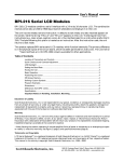
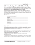
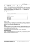
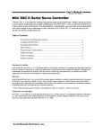
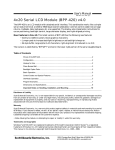
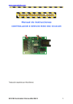
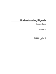
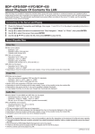
Distributed by:
www.Jameco.com ✦ 1-800-831-4242
The content and copyrights of the attached
material are the property of its owner.
Jameco Part Number 150990
User’s Manual
ILM-216 • v1.2 • 07/00 • pg 1
Integrated Serial LCD Module (ILM-216)
The ILM-216 combines an LCD and microcontroller into a compact module for user-interface applications.
• A 2-line by 16-character LCD with supertwist (high-contrast) screen
• Bidirectional serial interface, 1200 to 9600 baud
• Simple receive-terminal emulation
• Inputs for four pushbuttons or switches that may be read serially
• Output for piezo buzzer activated by ASCII bell character
• Nonvolatile EEPROM memory for configuration, special characters, startup screen
• Software control of LED backlight (on backlit models)
The ILM-216’s microcontroller is a PIC16F84, a flash-memory device that can be reprogrammed in
circuit. Sophisticated users can reprogram the module to their own specifications. This manual covers
only the standard firmware shipped with the ILM-216.
Table of Contents
Pinout of the ILM-216................................................................................................................2
Quick Checkout and Contrast Adjustment ................................................................................2
Hookup for Use .........................................................................................................................2
Basic Operation.........................................................................................................................3
Control Codes and Special Features ........................................................................................3
Configuration EEPROM ............................................................................................................6
Program Examples....................................................................................................................7
Dimensions and Specifications .................................................................................................8
Figure 1. Location of pins and contrast control..........................................................................2
Figure 2. Hookup example with accessories .............................................................................3
Figure 3. Connecting to PC serial port, BASIC Stamps ............................................................3
Figure 4. Defining a custom symbol ..........................................................................................6
Figure 5. Character code chart..................................................................................................7
Figure 6. Physical dimensions...................................................................................................8
Disclaimer of Liability
Scott Edwards Electronics, Inc. is not responsible for any special, incidental, or consequential damages resulting
from any breach of warranty, or under any legal theory, including lost profits, downtime, goodwill, damage to or
replacement of equipment or property, and any costs or recovering, reprogramming, or reproducing of data
associated with the use of the hardware or software described herein.
Warranty
Scott Edwards Electronics, Inc. warrants this product against defects in materials and workmanship for a period
of 90 days. If you discover a defect, we will, at our option, repair, replace, or refund the purchase price. Return
the product with a description of the problem. We will return your product or its replacement via standard shipping.
Expedited shipping is available at the customer’s expense.
• Note: Abusing the module, connecting reversed power, or attempting to repair or modify it, voids this warranty.
Trademarks and Copyrights
Windows® and MS-DOS® are registered trademarks of Microsoft Corporation; BASIC Stamp® is a registered
trademark of Parallax Inc. All trademarked names referenced herein are the property of their respective holders.
This manual in its entirety is copyright Scott Edwards Electronics, Inc., 1998–99.
Scott Edwards Electronics, Inc.
1939 S. Frontage Road, Suite F, Sierra Vista, AZ 85635 USA
ph: 520-459-4802 • fax: 520-459-0623 • www.seetron.com
User’s Manual
ILM-216 • v1.2 • 07/00 • pg 2
Pinout of the ILM-216
Connections to the ILM-216 are made through a row of solder pads located at the bottom edge of the
module (figure 1). Table 1 lists the pads’ functions.
front
back
contrast
control
darker
pin 1
pin 16
pin 16
pin 1
Figure 1. Location of pins and contrast control.
Table 1. Pins and Functions
Pin
Function
Notes
Function
Notes
1
GND
Do not reverse power!
Pin
9
S1a
Switch input S1
2
+5V
Do not reverse power!
10
S1b
GND
3
Serial In
RS-232 or 5-volt logic
11
S2a
Switch input S2
4
Serial Out
5-volt logic level, inverted
12
S2b
GND
5
Bell Out
25 mA max.
13
S3a
Switch input S3
6
GND
Ground for pins 7 and/or 8
14
S3b
GND
7
Config/Test Ground to configure
15
S4a
Switch input S4
8
Force 9600 Ground to force 9600 bps
16
S4b
GND
Do not reverse +5V and GND, even momentarily. Reversed power will destroy the electronics.
Do not exceed 5.5V into +5V. Overvoltage will damage the module or shorten its life.
Quick Checkout and Contrast Adjustment
Refer to figure 1. Temporarily connect pins 6 and 7 together. Apply power to pins 1 and 2, ensuring
proper polarity as indicated in table 1. When power is applied, the LCD will display the firmware
version and factory-configured baud rate, as shown in figure 1. (Actual text may vary.) The LCD contrast
is set at the factory. You may adjust it by turning the contrast control with a small, flat-blade screwdriver.
The baud rate shown on the test screen (2400 bps is the factory setting) indicates the baud rate stored
in the ILM-216’s configuration memory. This is the serial data rate the module will use in normal
operation (unless overridden by grounding pin 8). See “Configuration EEPROM.”
NOTE: When you are done with checkout, disconnect power and remove the connection between pins
6 and 7. This connection is for test and configuration and must be removed for normal operation.
Hookup for Use
Figure 2 shows how to connect serial I/O and accessories to the ILM-216. You may operate the module
without any or all accessories—just leave the unused pins disconnected. Many applications will require
just power and serial input.
Scott Edwards Electronics, Inc.
1939 S. Frontage Road, Suite F, Sierra Vista, AZ 85635 USA
ph: 520-459-4802 • fax: 520-459-0623 • www.seetron.com
User’s Manual
ILM-216 • v1.2 • 07/00 • pg 3
Figure 3 shows how to connect the module to PCs and BASIC Stamp computers in order to run the
example programs presented later in this manual.
1
DO NOT
REVERSE
POWER!
2
3
4
5
6
7
8
9
10
11
12
13
14
15
16
FRONT
VIEW
+5
computer
serial output
3
computer
serial input
4
S1
J1
S2
S3
J2
+5
J1: Short pin 7 to pin 6 (GND) for configuration/test
mode; leave open for normal operation.
5V, 25mA piezo buzzer
(e.g., Radio Shack 273-065)
S4
J2: Short pin 8 to pin 6 (GND) for 9600 baud
operation; leave open to use default baud rate (usually
2400 baud—shown on config/test screen).
S1 through S4: User-input buttons or
switches that may be read through
the serial link using the ESC-K n
instruction. Switches should be ESD
protected (as needed), and have low
(<10Ω) contact resistance.
Figure 2. Hookup example with accessories.
PC Serial (comm) Port
BASIC Stamps
NOTE: ILM-216 serial
output is 0–5V only, not
true RS-232 (±10V). Most
PCs can accept this signal,
but cable should be as
short as possible.
1
ILM-216
pin 4 (serial out)
pin 3 (serial in)
2
3
4
5
pin 1 (GND)
+5
6
DB-9 female
(solder side)
7
8
ILM-216
Stamp
GND (Vss)
pin 1 (GND)
+5V (Vdd)
pin 2 (+5V)
I/O pin 0
pin 3 (serial in)
I/O pin 1
pin 4 (serial out)
pin 2 (+5V)
9
power
supply
Figure 3. Connecting to PC serial port, BASIC Stamps.
Basic Operation
Connect serial input and power to the ILM-216 as shown in the previous sections. Make sure that pins
6 and 7 are not connected together (configuration/test mode). If they are, remove power, disconnect
pins 6 and 7, and restore power.
Now you can send text serially to the display. On a PC, you may use a terminal program (such as
Hyperterminal, included with Windows 95 and later). Set it for the appropriate baud rate (the one you
saw on the config/test screen; 2400 is the factory default). To override that baud rate and run at 9600
baud, connect pin 8 to pin 6 as shown in figure 2 above. In addition to the baud rate, the terminal
should be set for:
no parity
8 data bits
1 stop bit
flow control = none
local echo = on
Control Codes and Special Feaures
Table 2 lists the ILM-216 control codes. To send control codes from a terminal program, hold down
Control and press another key. For example, to send ctrl-E (underline cursor) hold down Control and
press E. To send control codes from a program, send the ASCII value as a single byte (not as a text
representation of the number). Using ctrl-E as an example, send a single byte containing the value 5
(00000101 binary). Control codes not listed in the table are ignored by the ILM-216 and have no effect.
Scott Edwards Electronics, Inc.
1939 S. Frontage Road, Suite F, Sierra Vista, AZ 85635 USA
ph: 520-459-4802 • fax: 520-459-0623 • www.seetron.com
User’s Manual
ILM-216 • v1.2 • 07/00 • pg 4
Table 2. Display Control Codes
Function
Null (ignored prior to buffer)
Cursor home
Hide cursor
Show underline cursor
Show blinking-block cursor
Bell (pulse piezo-buzzer output)
Backspace*
Horizontal tab (cursor to next multiple-of-4 column)*
Smart linefeed (cursor down one line)
Vertical tab (cursor up one line)
Formfeed (clear screen)
Carriage return*
Backlight on
Backlight off
Accept cursor-position entry
Format right-aligned text
Escape (ESC; start multipart instruction)
Code
ASCII
ctrl-@
ctrl-A
ctrl-D
ctrl-E
ctrl-F
ctrl-G
ctrl-H
ctrl-I
ctrl-J
ctrl-K
ctrl-L
ctrl-M
ctrl-N
ctrl-O
ctrl-P
ctrl-R
ctrl-[
0
1
4
5
6
7
8
9
10
11
12
13
14
15
16
18
27
• Define graphics character: ESC D n B0 B1 B2 B3 B4 B5 B6 B7
where n is the character number (0—7) and B0—B7 are bytes mapping the pixels
• Transfer data from EEPROM to display: ESC E n
where n is “0” or “1” with 0 meaning text screen and 1 meaning symbols
• Read the keys (S1—S4) and report serially: ESC K n
where n sets format—0 = single byte, bits 0—3 correspond to S1—S4 and
1= four bytes consisting of text characters “0” and “1” (a “1” means switch closed)
Null (control-@, ASCII 0)
Nulls are ignored; sending a null to the display has no effect. However, unlike other unused codes, nulls
are not even stored in the display buffer. They may be used as a brief time delay whose length depends
on the baud rate: 1200 bps = 8.33 ms delay; 2400 bps = 4.16 ms; 4800 bps = 2.08 ms; 9600 bps = 1.04 ms.
Cursor Home (control-A, ASCII 1)
Move the cursor to the first character position of the first line.
Hide Cursor (control-D, ASCII 4)
Hide the cursor (either type, blinking or underline).
Show Underline Cursor (control-E, ASCII 5)
Show a non-blinking underline cursor at the printing location.
Show Blinking-Block Cursor (control-F, ASCII 6)
Show a blinking block cursor at the printing location.
Bell (control-G, ASCII 7)
Pulse pin 5 low for approximately 100 ms to beep piezo buzzer.
Backspace (control-H or backspace key, ASCII 8)
Move the cursor back one space and erase the character in that space.
Horizontal Tab (control-I or Tab key, ASCII 9)
Move the cursor forward to next multiple-of-four column.
Smart Linefeed (control-J, ASCII 10)
Move cursor down one line. If immediately preceded by carriage return, linefeed is ignored.
Vertical Tab (control-K, ASCII 11)
Move cursor up one line.
Scott Edwards Electronics, Inc.
1939 S. Frontage Road, Suite F, Sierra Vista, AZ 85635 USA
ph: 520-459-4802 • fax: 520-459-0623 • www.seetron.com
User’s Manual
ILM-216 • v1.2 • 07/00 • pg 5
Clear Screen (control-L, ASCII 12)
Clear the screen.
Carriage Return (control-M, ASCII 13)
Move cursor to the first position of the next line.
Backlight ON (control-N, ASCII 14)
Turn on the LED backlight. Current draw is approximately 40 mA.
Backlight OFF (control-O, ASCII 15)
Turn off the LED backlight.
Position Cursor (control-P, ASCII 16)
Accept a number from 0 to 31 and move the cursor to that screen position (where 0 is the first character
of the first line and 31 is the last character of the second line). Number may be in text or single-byte format:
Text method: Send the desired display position as printable text. For example, to move the cursor to position
21 (6th character, 2nd line) from a terminal program, press control-P, and type “21” followed by a space
or other character (which will be discarded).
One-byte method: Send a single byte whose value is 64 + position. For example, to move to position 21,
send a control-P (ASCII 16) followed by a byte value of 85 (64 + 21).
Right-align Text (control-R, ASCII 18)
Accept a number from 2 to 9 (as text) representing the width of an area on the screen in which rightaligned text is to be printed. Cursor will back up that number of characters from present cursor position.
Subsequent text will be stored without printing to the screen until one of the following is received:
• The specified number of characters.
• A control character (ASCII 1–31).
• A decimal point (the period (.) character, ASCII 46).
The display will print the text with right alignment and erase any leftover text within the specified width.
For example, move the cursor to the right end of the screen, send control-R (ASCII 18), followed by “5”
(ASCII 53), then “123” and Enter. The “123” will be printed right-aligned within the 5-character space.
Escape Sequences (control-[, ASCII 27, followed by additional instructions)
The ILM-216 has eight custom-character slots. These characters are
mapped to ASCII codes 128 through 134. At startup, the unit loads
bitmaps into the first six custom characters from its EEPROM. Using
the Define instruction, you can change a bitmap. Send Escape (ASCII
27) followed by the letter D (ASCII 68), then the symbol number you
wish to define (0—7, ASCII 48—55), followed by eight bytes defining
the bitmap. The contents of those bytes map to the custom symbol as
shown in figure 4.
bit 0
bit 1
bit 2
• Define a Custom Character (ESC D n B0 B1 B2 B3 B4 B5 B6 B7)
bit 3
bit 4
The ILM-216 understands three instructions that begin with the escape code (ASCII 27).
Byte Values
byte 0
binary
xxx00000
decimal
0
byte 1
xxx00100
4
byte 2
xxx00010
2
byte 3
xxx11111
31
byte 4
xxx00010
2
byte 5
xxx00100
4
byte 6
xxx00000
0
byte 7
xxx00000
0
Figure 4. Defining a custom symbol.
• Transfer Data from EEPROM (ESC E n)
The ILM-216 has 64 bytes of EEPROM, which may be used to store configuration data, such as text for a
startup screen or default patterns for the first six custom characters (ASCII 128 through 133). Using the
EEPROM instruction, you can transfer that data from EEPROM to the display. Send Escape (ASCII 27),
followed by the letter E (ASCII 69), then the number 0 or 1 (ASCII 48 or 49) to perform a transfer. ESC
E 0 causes the EEPROM text screen to be displayed. ESC E 1 reloads the first six custom characters from
EEPROM. Since those custom characters are automatically loaded at startup, the only time you might
use ESC E 1 is to undo changes made by a previous definition of custom characters (ESC D n...).
Scott Edwards Electronics, Inc.
1939 S. Frontage Road, Suite F, Sierra Vista, AZ 85635 USA
ph: 520-459-4802 • fax: 520-459-0623 • www.seetron.com
User’s Manual
ILM-216 • v1.2 • 07/00 • pg 6
• Read the Keys (ESC K n)
The ILM has four inputs that may be used to read a four-button keypad (S1—S4). The Key instruction
returns the states of those switches via the serial output. Send Escape (ASCII 27) followed by K (ASCII
75), then the number 0 or 1 (ASCII 48 or 49). ESC K 0 returns a single byte whose lower four bits correspond
to the states of the keys (where 0 means open and 1 means closed). S1 corresponds to bit 0, S2 to bit 1 and
so on. The upper four bits will always be 0100 binary. If you send ESC K 0 from a terminal, you will see
the returned byte as a single character: @ (no keys pressed), or A through O (one or more keys pressed).
ESC K 1 returns four bytes consisting of 0 (ASCII 48) for open switches and 1 (ASCII 49) for closed switches.
From a terminal, you would see “0100” assuming that S2 was closed and the others open.
Configuration EEPROM
The ILM-216 stores settings, custom characters, and a 32-character text screen in 64 bytes of EEPROM.
This kind of memory retains its contents without power. Table 3 shows the format of the EEPROM
configuration. Configuration software is available from www.seetron.com.
To download data to the EEPROM, connect the ILM-216 to a PC as shown in figure 3. Temporarily
connect pins 6 and 7 of the ILM-216 together, and power the unit. It will display the screen shown in
figure 1 (with some possible variations in the text). The ILM-216 is waiting to receive 64 bytes that it
will copy to EEPROM. The download baud rate is fixed at 2400 bps. Select the desired settings in the
configuration software and press Download (Windows version; see readme file accompanying DOS
version). When the download is over, the screen will display “Setup Complete.” To use the ILM-216,
turn off power and disconnect pins 6 and 7.
Configuration software is available free from www.seetron.com (downloads page)
Table 3. Configuration Bytes
Byte No.
Function
Explanation
0—29
Custom symbols
Each of 6 symbols is defined by 8 rows of 5 bits, for a total of 240 bits packed into 30
bytes. For example config byte 0 contains symbol 0, row 0, bits 0—4 and symbol 0, row
1, bits 0—2.
30
Settings,
Power-on delay
Bits 1 and 0 set the baud rate: 00 = 9600, 01 = 4800, 10 = 2400, 11 = 1200
Bit 2 determines backlight status at startup: 0 = OFF, 1 = ON
Bit 3 determines screen status at startup: 0 = blank, 1 = EEPROM text (bytes 32—63)
Bits 4 through 7 form a four-bit value (0—15) that sets a startup delay in units of 2.5
seconds (0 to 37.5 seconds). After power is applied, the ILM-216 ignores its serial input
for the startup-delay time (firmware v28 and higher).
31
Key delay
Bits 0—3 form a four-bit value (0—15) that sets the delay (in 0.5-ms units) before response
to an ESC K keypad query. (Delay lets slow computers prepare for serial receive.) Bits
4–7 are unused.
Screen text
A 32-byte string that is written to the screen at startup (if bit 3 of byte 30 above is 1), or
whenever an ESC E 1 instruction is received.
32—63
Factory Settings. The ILM-216 ships with default settings loaded into its EEPROM. The custom
characters are as shown in figure 5; the default baud rate is 2400 bps (which may be changed to 9600
by shorting pin 8 to pin 6 or other GND); at startup the backlight is off and the screen is blank; the
delay after an ESC K key read is set to 2.5 ms; startup delay is 0; and the screen text (displayable by
ESC E 0) is set to “Scott Edwards Electronics Inc.” or custom text requested by a distributor.
Scott Edwards Electronics, Inc.
1939 S. Frontage Road, Suite F, Sierra Vista, AZ 85635 USA
ph: 520-459-4802 • fax: 520-459-0623 • www.seetron.com
User’s Manual
ILM-216 • v1.2 • 07/00 • pg 7
32
40
48
56
64
72
80
88
96
104 112 120 128 160 168 176 184 192 200 208 216 224 232 240 248
0
1
2
3
4
5
6
7
To find the ASCII code for a given character, add the row and column numbers.
For example, capital D is in the column marked 64 in row 4, so its ASCII code is
68. Use the reverse procedure to determine the symbol for a given code. For
example, ASCII code 244 produces the symbol Ω, found at colum 240, row 4.
NOTE: Custom characters occupy ASCII 128–135
ASCII 128–133 load from configuration EEPROM
ASCII 136–160 are blanks
Figure 5. Character code chart
Program Examples
Any computer/programming language that can produce serial output (1200 to 9600 bps, N81) can talk
to the ILM-216. The examples here are in BASIC, chosen because of its popularity and readability. (A
C programmer can readily understand BASIC, but a BASIC programmer generally cannot read C.)
These examples are meant to illustrate only the fundamentals. More examples are available from
www.seetron.com.
' BASIC STAMP I
' Assumes ILM-216 set for 2400 bps (factory default), serial in (pin 3) connected
' to BS1 pin 0. Uses ctrl-P (position, ASCII 16) and ctrl-L (clear screen, ASCII 12)
PAUSE 1000
' Wait for display to initialize.
SEROUT 0,N2400,(12,"Hello World!")
' Clear screen, show message.
PAUSE 2000
' Wait 2 secs, go to line 2, character 5 (position 21-SEROUT 0,N2400,(16,85,"line 2") ' ..64 + 21 = 85)..and print.
PAUSE 2000: SEROUT 0,N2400,(12, "Goodbye.")
' Wait 2 seconds, clear screen, say bye.
' BASIC STAMP II
' Assumes ILM-216 set for 2400 bps (factory default), serial in (pin 3) connected
' to BS2 pin P0. Uses ctrl-P (position, ASCII 16) and ctrl-L (clear screen, ASCII 12)
' If ILM-216 is set for 9600 bps, use $4054 ($40F0 for BS2-SX) as Serout baudmode.
N2400 con $418D
' Define inverted, 2400-bps serial ($43FD for BS2-SX)
PAUSE 1000
' Wait for display to initialize.
SEROUT 0,N2400,[12,"Hello World!"]
' Clear screen, show message.
PAUSE 2000
' Wait 2 seconds, then go to line 2 (position 16-SEROUT 0,N2400,[16,85,"line 2..."]
' ..64 + 21 = 85) and print.
PAUSE 2000:SEROUT 0,N2400,[12,"Goodbye."]
' Wait 2 secs, clear screen, say bye.
Scott Edwards Electronics, Inc.
1939 S. Frontage Road, Suite F, Sierra Vista, AZ 85635 USA
ph: 520-459-4802 • fax: 520-459-0623 • www.seetron.com
User’s Manual
ILM-216 • v1.2 • 07/00 • pg 8
Program Examples (cont.)
' QBASIC, QuickBASIC, PowerBASIC (including First BASIC) for PCs under DOS
' Note: QBASIC is the BASIC interpreter that Microsoft shipped with most versions of
' DOS. An alternative is PowerBASIC or First BASIC, from www.powerbasic.com (or go
' to www.seetron.com and follow the link from the ILM-216 support page).
' Program assumes ILM-216 set for 2400 bps (factory default), connected
' as shown in figure 3. If you are using a serial port other than com1,
' modify the OPEN instruction accordingly. Program uses ctrl-P (position,
' ASCII 16) and ctrl-L (clear screen, ASCII 12).
OPEN "COM1:2400,N,8,1,CD0,CS0,DS0" FOR OUTPUT AS #1 ' Open the serial port.
PRINT #1, CHR$(12);"Hello World"; ' Clear screen, show message.
' Now move to the middle of line 2 (position 21; 64 + 21 = 85) and print.
PRINT #1, CHR$(16);CHR$(85);"Line 2";
' Print in middle of line 2.
INPUT "Press Enter",X$
' Wait for a key press.
PRINT #1,CHR$(12);"Goodbye.";
' Clear screen, say bye.
Dimensions and Specifications
Additional information not covered by this manual (schematic, more program examples, configuration
downloading utility, developer program, etc.) may be obtained from www.seetron.com. You may also
request hardcopy by mail.
Dim.
A
B
C
D
E
F
G
H
I
J
K
L
M
N
O
-
y offset edge to hole ctr (top & btm)
y pcb height
y hole spacing (inside pair)
y screen opening
y character size
x character size
x offset pcb edge to hole ctr
x screen frame
x screen opening
x hole spacing
x pcb width
y frame height
y hole spacing (outside pair)
x offset hole ctr to pin 1
x offset between pads
mounting hole diameter
frame depth, LED-backlit
H
2.50
50.00
31.00
16.20
5.94
2.95
2.50
71.00
66.00
75.00
80.00
25.00
45.00
5.50
2.54
2.50
8.50
A
B
C
I
E
D
L
F
M
O
1
N
• All dimensions in mm.
• Worst-case tolerance for any dimension is ±0.50mm.
• Maximum depth (from front of screen frame to highest
point on pcb) is 15mm
G
16
J
K
Figure 6. Physical dimensions
Table 4. Basic
Specifications
Power requirements.....................4.8 to 5.5 Vdc @ 5 mA (40 mA, backlit)
User connector...................................................16 pads on 0.10" centers
Connector pinout......................................................................see table 1
Serial input ................RS-232, or inverted TTL/CMOS, 1200—9600, N81
Serial output .........................inverted TTL; 0=5V, 1=0V (not true RS-232)
Buffer depth..................................................................................16 bytes
Operating temperature......................................0° to 50°C (32° to 122°F)
Storage temperature ......................................–10° to 60°C (14° to 140°F)
LCD type ..................................................Supertwist (STN), yellow-green
Optimum viewing direction...........................................................6 o'clock
Scott Edwards Electronics, Inc.
1939 S. Frontage Road, Suite F, Sierra Vista, AZ 85635 USA
ph: 520-459-4802 • fax: 520-459-0623 • www.seetron.com