1
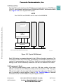
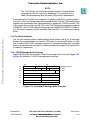
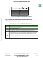
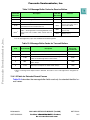
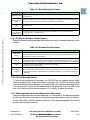
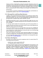
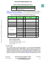
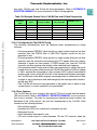
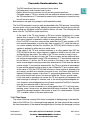
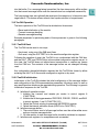
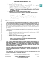
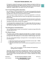
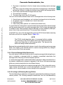
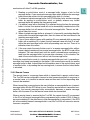
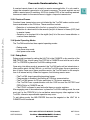
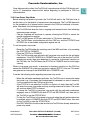
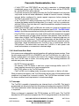
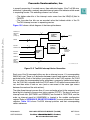
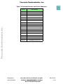
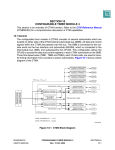
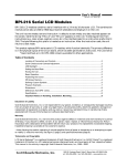
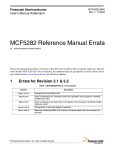
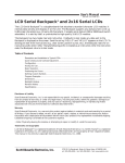
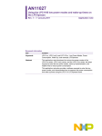
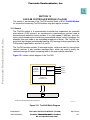
Freescale Semiconductor, Inc.
SECTION 13
CAN 2.0B CONTROLLER MODULE (TouCAN)
Freescale Semiconductor, Inc...
This section is an overview of the TouCAN module. Refer to D.10 TouCAN Module
for information concerning TouCAN address map and register structure.
13.1 General
The TouCAN module is a communication controller that implements the controller
area network (CAN) protocol, an asynchronous communications protocol used in
automotive and industrial control systems. It is a high speed (1 Mbit/sec), short distance, priority based protocol which can communicate using a variety of mediums (for
example, fiber optic cable or an unshielded twisted pair of wires). The TouCAN supports both the standard and extended identifier (ID) message formats specified in the
CAN protocol specification, revision 2.0, part B.
The TouCAN module contains 16 message buffers, which are used for transmit and
receive functions. It also contains message filters, which are used to qualify the
received message IDs when comparing them to the receive buffer identifiers.
Figure 13-1 shows a block diagram of the TouCAN.
CANTX0
TRANSMITTER
16RX/TX
MESSAGE
BUFFERS
CANTX1*
CONTROL
RECEIVER
CANRX0
CANRX1*
SLAVE BUS
INTERFACE UNIT
IMB
* THESE PINS ARE NOT BONDED ON THE MC68376
TOUCAN BLOCK
Figure 13-1 TouCAN Block Diagram
MC68336/376
USER’S MANUAL
CAN 2.0B CONTROLLER MODULE (TouCAN)
MOTOROLA
Rev. 15 Oct 2000
For More Information
On This Product,
Go to: www.freescale.com
13-1
Freescale Semiconductor, Inc.
13.2 External Pins
The TouCAN module interface to the CAN bus is composed of four pins: CANTX0 and
CANTX1, which transmit serial data, and CANRX0 and CANRX1, which receive serial
data. Figure 13-2 shows a typical CAN system.
NOTE
Pins CANTX1 and CANRX1 are not used on the MC68376.
Freescale Semiconductor, Inc...
CAN STATION 1
CAN STATION 2
CAN STATION n
CAN SYSTEM
CAN
CONTROLLER
(TOUCAN)
……
CANTX0 CANTX1* CANRX0 CANRX1*
TRANSCEIVER
* THESE PINS ARE NOT BONDED ON THE MC68376
CAN SYSTEM
Figure 13-2 Typical CAN Network
Each CAN station is connected physically to the CAN bus through a transceiver. The
transceiver provides the transmit drive, waveshaping, and receive/compare functions
required for communicating on the CAN bus. It can also provide protection against
damage to the TouCAN caused by a defective CAN bus or a defective CAN station.
13.3 Programmer’s Model
The TouCAN module address space is split into 128 bytes starting at the base
address, and then an extra 256 bytes starting at the base address +128. The upper
256 are fully used for the message buffer structures. Out of the lower 128 bytes, only
part is occupied by various registers. Refer to D.10 TouCAN Module for detailed
information on the TouCAN address map and register structure.
MC68336/376
USER’S MANUAL
CAN 2.0B CONTROLLER MODULE (TouCAN)
MOTOROLA
Rev. 15 Oct 2000
For More Information
On This Product,
Go to: www.freescale.com
13-2
Freescale Semiconductor, Inc.
NOTE
The TouCAN has no hard-wired protection against invalid bit/field
programming within its registers. Specifically, no protection is provided if the programming does not meet CAN protocol requirements.
Freescale Semiconductor, Inc...
Programming the TouCAN control registers is typically done during system initialization, prior to the TouCAN becoming synchronized with the CAN bus. The configuration
registers can be changed after synchronization by halting the TouCAN module. This
is done when the user sets the HALT bit in the TouCAN module configuration register
(CANMCR). The TouCAN responds by asserting the CANMCR NOTRDY bit. Additionally, the control registers can be modified while the MCU is in background debug
mode.
13.4 TouCAN Architecture
The TouCAN module utilizes a flexible design which allows each of its 16 message
buffers to be assigned either as a transmit (TX) buffer or a receive (RX) buffer. In addition, to reduce the CPU32 overhead required for message handling each message
buffer is assigned an interrupt flag bit to indicate successful completion of transmission
or reception, respectively.
13.4.1 TX/RX Message Buffer Structure
Figure 13-3 displays the extended (29 bit) ID message buffer structure. Figure 13-4
displays the standard (11 bit) ID message buffer structure.
158
$0
$2
74
TIME STAMP
30
CODE
ID[28:18]
$4
LENGTH
SRR
IDE
ID[17:15]
ID[14:0]
ID_HIGH
RTR ID_LOW
$6
DATA BYTE 0
DATA BYTE 1
$8
DATA BYTE 2
DATA BYTE 3
$A
DATA BYTE 4
DATA BYTE 5
$C
DATA BYTE 6
DATA BYTE 7
$E
CONTROL/STATUS
RESERVED
Figure 13-3 Extended ID Message Buffer Structure
MC68336/376
USER’S MANUAL
CAN 2.0B CONTROLLER MODULE (TouCAN)
MOTOROLA
Rev. 15 Oct 2000
For More Information
On This Product,
Go to: www.freescale.com
13-3
Freescale Semiconductor, Inc.
15
$0
8 7
TIME STAMP
$2
4 3
CODE
ID[28:18]
$4
0
LENGTH
RTR
0
0
0
16-BIT TIME STAMP
$6
DATA BYTE 0
DATA BYTE 1
$8
DATA BYTE 2
DATA BYTE 3
$A
DATA BYTE 4
DATA BYTE 5
$C
DATA BYTE 6
DATA BYTE 7
$E
CONTROL/STATUS
0
ID_HIGH
ID_LOW
RESERVED
Freescale Semiconductor, Inc...
Figure 13-4 Standard ID Message Buffer Structure
13.4.1.1 Common Fields for Extended and Standard Format Frames
Table 13-1 describes the message buffer fields that are common to both extended and
standard identifier format frames.
Table 13-1 Common Extended/Standard Format Frames
Field
Description
Time Stamp
Contains a copy of the high byte of the free running timer, which is captured at the beginning of the
identifier field of the frame on the CAN bus.
Code
Refer to Tables 13-2 and 13-3
RX Length
Length (in bytes) of the RX data stored in offset $6 through $D of the buffer. This field is written by
the TouCAN module, copied from the DLC (data length code) field of the received frame.
TX Length
Length (in bytes) of the data to be transmitted, located in offset $6 through $D of the buffer. This field
is written by the CPU32, and is used as the DLC field value. If RTR (remote transmission request)
= 1, the frame is a remote frame and will be transmitted without data field, regardless of the value in
TX length.
Data
This field can store up to eight data bytes for a frame. For RX frames, the data is stored as it is received from the bus. For TX frames, the CPU32 provides the data to be transmitted within the frame.
Reserved
This word entry field (16 bits) should not be accessed by the CPU32.
MC68336/376
USER’S MANUAL
CAN 2.0B CONTROLLER MODULE (TouCAN)
MOTOROLA
Rev. 15 Oct 2000
For More Information
On This Product,
Go to: www.freescale.com
13-4
Freescale Semiconductor, Inc.
Table 13-2 Message Buffer Codes for Receive Buffers
RX Code
Before RX
New Frame
0000
NOT ACTIVE — message buffer is not active.
0100
EMPTY — message buffer is active and empty.
0010
FULL — message buffer is full.
0110
OVERRUN — second frame was received into a full
buffer before the CPU read the first one.
0XY11
Freescale Semiconductor, Inc...
Description
BUSY — message buffer is now being filled with a new
receive frame. This condition will be cleared within 20
cycles.
RX Code
After RX
New Frame
Comment
—
—
0010
—
0110
If a CPU32 read occurs before the new frame, new receive code is 0010.
0010
An empty buffer was filled
(XY was 10).
0110
A full/overrun buffer was
filled (Y was 1).
NOTES:
1. For TX message buffers, upon read, the BUSY bit should be ignored.
Table 13-3 Message Buffer Codes for Transmit Buffers
Description
Code After
Successful
Transmission
RTR
Initial TX Code
X
1000
0
1100
Data frame to be transmitted once, unconditionally.
1000
1
1100
Remote frame to be transmitted once, and message buffer becomes an RX message buffer for data frames.
0100
0
10101
Data frame to be transmitted only as a response to a remote
frame, always.
1010
0
1110
Data frame to be transmitted only once, unconditionally, and
then only as a response to remote frame, always.
1010
Message buffer not ready for transmit.
—
NOTES:
1. When a matching remote request frame is detected, the code for such a message buffer is changed to be
1110.
13.4.1.2 Fields for Extended Format Frames
Table 13-4 describes the message buffer fields used only for extended identifier format frames.
MC68336/376
USER’S MANUAL
CAN 2.0B CONTROLLER MODULE (TouCAN)
MOTOROLA
Rev. 15 Oct 2000
For More Information
On This Product,
Go to: www.freescale.com
13-5
Freescale Semiconductor, Inc.
Table 13-4 Extended Format Frames
Field
Description
Contains the 14 most significant bits of the extended identifier, located in the ID HIGH word of the
ID[28:18]/[17:15]
message buffer.
Substitute
Contains a fixed recessive bit, used only in extended format. Should be set to one by the user for
Remote Request
TX buffers. It will be stored as received on the CAN bus for RX buffers.
(SRR)
Freescale Semiconductor, Inc...
ID Extended
(IDE)
If extended format frame is used, this field should be set to one. If zero, standard format frame
should be used.
ID[14:0]
Bits [14:0] of the extended identifier, located in the ID LOW word of the message buffer.
Remote
Transmission
Request (RTR)
This bit is located in the least significant bit of the ID LOW word of the message buffer;
0 = Data Frame, 1 = Remote Frame.
13.4.1.3 Fields for Standard Format Frames
Table 13-5 describes the message buffer fields used only for standard identifier format
frames.
Table 13-5 Standard Format Frames
Field
Description
16-Bit Time
Stamp
The ID LOW word, which is not needed for standard format, is used in a standard format buffer
to store the 16-bit value of the free-running timer which is captured at the beginning of the identifier field of the frame on the CAN bus.
ID[28:18]
Contains bits [28:18] of the identifier, located in the ID HIGH word of the message buffer. The four
least significant bits in this register (corresponding to the IDE bit and ID[17:15] for an extended
identifier message) must all be written as logic zeros to ensure proper operation of the TouCAN.
RTR
RTR/SRR Bit
Treatment
This bit is located in the ID HIGH word of the message buffer;
0 = data frame, 1 = remote frame.
If the TouCAN transmits this bit as a one and receives it as a zero, an “arbitration loss” is indicated. If the TouCAN transmits this bit as a zero and is receives it as a one, a bit error is indicated.
If the TouCAN transmits a value and receives a matching response, a successful bit transmission
is indicated.
13.4.1.4 Serial Message Buffers
To allow double buffering of messages, the TouCAN has two shadow buffers called
serial message buffers. These two buffers are used by the TouCAN for buffering both
received messages and messages to be transmitted. Only one serial message buffer
is active at a time, and its function depends upon the operation of the TouCAN at that
time. At no time does the user have access to or visibility of these two buffers.
13.4.1.5 Message Buffer Activation/Deactivation Mechanism
Each message buffer must be activated once it is configured for the desired operation
by the user. A buffer is activated by writing the appropriate code to the control/status
word for that buffer. Once the buffer is activated, it will begin participating in the normal
transmit and receive processes.
MC68336/376
USER’S MANUAL
CAN 2.0B CONTROLLER MODULE (TouCAN)
MOTOROLA
Rev. 15 Oct 2000
For More Information
On This Product,
Go to: www.freescale.com
13-6
Freescale Semiconductor, Inc.
Likewise, a buffer is deactivated by writing the appropriate deactivation code to the
control/status word for that buffer. Deactivation of a buffer is typically done when the
user desires to reconfigure the buffer, for example to change the buffer’s function (RX
to TX or TX to RX). Deactivation should also be done before changing a receive
buffer’s message identifier or before loading a new message to be transmitted into a
transmit buffer.
Freescale Semiconductor, Inc...
For more details on activation and deactivation of message buffers, and the effects on
message buffer operation, refer to 13.5 TouCAN Operation.
13.4.1.6 Message Buffer Lock/Release/Busy Mechanism
In addition to the activation/deactivation mechanism, the TouCAN also utilizes a lock/
release/busy mechanism to assure data coherency during the receive process. The
mechanism includes a lock status for each message buffer, and utilizes the two serial
message buffers to facilitate frame transfers within the TouCAN.
Reading the control/status word of a receive message buffer triggers the lock for that
buffer. While locked, a received message cannot be transferred into that buffer from
one of the SMBs.
If a message transfer between the message buffer and a serial message buffer is in
progress when the control/status word is read, the BUSY status will be indicated in the
code field, and the lock will not be activated.
The user can release the lock on a message buffer in one of two ways. Reading the
control/status word of another message buffer will lock that buffer, releasing the previously locked buffer. A global release can also be performed on any locked message
buffer by reading the free-running timer.
Once a lock is released, any message transfers between an SMB and a message buffer which was delayed due to that buffer being locked will take place. For more details
on the message buffer locking mechanism, and the effects on message buffer operation, refer to 13.5 TouCAN Operation.
13.4.2 Receive Mask Registers
The receive mask registers are used as acceptance masks for received frame IDs.
The following masks are defined:
• A global mask, used for receive buffers 0-13
• Two separate masks for buffers 14 and 15
The value of the mask registers should not be changed during normal operation. If the
mask register data is changed after the masked identifier of a received message is
matched to a locked message buffer, that message will be transferred into that message buffer once it is unlocked, regardless of whether that message’s masked
identifier still matches the receive buffer identifier. Table 13-6 shows mask bit values.
MC68336/376
USER’S MANUAL
CAN 2.0B CONTROLLER MODULE (TouCAN)
MOTOROLA
Rev. 15 Oct 2000
For More Information
On This Product,
Go to: www.freescale.com
13-7
Freescale Semiconductor, Inc.
Table 13-6 Receive Mask Register Bit Values
Mask Bit
Values
0
The corresponding incoming ID bit is “don’t care”.
1
The corresponding ID bit is checked against the incoming ID
bit to see if a match exists.
Table 13-7 shows mask examples for normal and extended messages. Refer to
APPENDIX D REGISTER SUMMARY for more information on RX mask registers.
Freescale Semiconductor, Inc...
Table 13-7 Mask Examples for Normal/Extended Messages
Message Buffer (MB)
/Mask
Base ID
ID[28:18]
IDE
Extended ID
ID[17:0]
Match
MB2
11111111000
0
—
—
MB3
1111111100
0
1
MB4
00000011111
0
—
—
MB5
00000011101
1
010101010101010101
—
MB14
11111111000
1
010101010101010101
—
RX Global Mask
11111111110
111111100000000001
—
RX Message In
RX 14 Mask
RX Message In
010101010101010101
—
11111111001
1
010101010101010101
31
11111111001
0
—
22
11111111001
1
010101010101010100
—3
01111111000
0
—
—4
01111111000
1
010101010101010101
—5
111111100000000000
—
01111111111
10111111000
1
010101010101010101
—6
01111111000
1
010101010101010101
147
NOTES:
1. Match for extended format (MB3).
2. Match for standard format (MB2).
3. No match for MB3 because of ID0.
4. No match for MB2 because of ID28.
5. No match for MB3 because of ID28, match for MB14.
6. No match for MB14 because of ID27.
7. Match for MB14.
13.4.3 Bit Timing
The TouCAN module uses three 8-bit registers to set-up the bit timing parameters
required by the CAN protocol. Control registers 1 and 2 (CANCTRL1, CANCTRL2)
contain the PROPSEG, PSEG1, PSEG2, and the RJW fields which allow the user to
configure the bit timing parameters. The prescaler divide register (PRESDIV) allows
the user to select the ratio used to derive the S-clock from the system clock. The time
quanta clock operates at the S-clock frequency. Table 13-8 provides examples of sys-
MC68336/376
USER’S MANUAL
CAN 2.0B CONTROLLER MODULE (TouCAN)
MOTOROLA
Rev. 15 Oct 2000
For More Information
On This Product,
Go to: www.freescale.com
13-8
Freescale Semiconductor, Inc.
tem clock, CAN bit rate, and S-clock bit timing parameters. Refer to APPENDIX D
REGISTER SUMMARY for more information on the bit timing registers.
Freescale Semiconductor, Inc...
Table 13-8 Example System Clock, CAN Bit Rate and S-Clock Frequencies
System Clock
Frequency
(MHz)
CAN Bit-Rate
(MHz)
Possible S-Clock
Frequency (MHz)
Possible Number of
Time Quanta/Bit
PRESDIV Value + 1
25
1
25
25
1
20
1
10, 20
10, 20
2, 1
16
1
8, 16
8, 16
2, 1
25
0.125
1, 1.25, 2.5
8,10, 20
25, 20,10
20
0.125
1, 2, 2.5
8, 16, 20
20, 10, 8
16
0.125
1, 2
8,16
16, 8
13.4.3.1 Configuring the TouCAN Bit Timing
The following considerations must be observed when programming bit timing
functions.
• If the programmed PRESDIV value results in a single system clock per one time
quantum, then the PSEG2 field in CANCTRL2 register should not be programmed to zero.
• If the programmed PRESDIV value results in a single system clock per one time
quantum, then the information processing time (IPT) equals three time quanta,
otherwise it equals two time quanta. If PSEG2 equals two, then the TouCAN
transmits one time quantum late relative to the scheduled sync segment.
• If the prescaler and bit timing control fields are programmed to values that result
in fewer than ten system clock periods per CAN bit time and the CAN bus loading
is 100%, anytime the rising edge of a start-of-frame (SOF) symbol transmitted by
another node occurs during the third bit of the intermission between messages,
the TouCAN may not be able to prepare a message buffer for transmission in time
to begin its own transmission and arbitrate against the message which transmitted the early SOF.
• The TouCAN bit time must be programmed to be greater than or equal to nine
system clocks, or correct operation is not guaranteed.
13.4.4 Error Counters
The TouCAN has two error counters, the transmit (TX) error counter and the receive
(RX) error counter. Refer to APPENDIX D REGISTER SUMMARY for more information on error counters. The rules for increasing and decreasing these counters are
described in the CAN protocol, and are fully implemented in the TouCAN. Each
counter has the following features:
• 8-bit up/down counter
• Increment by 8 (RX error counter also increments by one)
• Decrement by one
• Avoid decrement when equal to zero
• RX error counter reset to a value between 119 and 127 inclusive, when the
MC68336/376
USER’S MANUAL
CAN 2.0B CONTROLLER MODULE (TouCAN)
MOTOROLA
Rev. 15 Oct 2000
For More Information
On This Product,
Go to: www.freescale.com
13-9
Freescale Semiconductor, Inc.
TouCAN transitions from error passive to error active
• Following reset, both counters reset to zero
• Detect values for error passive, bus off and error active transitions
• Cascade usage of TX error counter with an additional internal counter to detect
the 128 occurrences of 11 consecutive recessive bits necessary to transition from
bus off into error active.
Both counters are read only (except in test/freeze/halt modes).
Freescale Semiconductor, Inc...
The TouCAN responds to any bus state as described in the CAN protocol, transmitting
an error active or error passive flag, delaying its transmission start time (error passive)
and avoiding any influence on the bus when in the bus off state. The following are the
basic rules for TouCAN bus state transitions:
• If the value of the TX error counter or RX error counter increments to a value
greater than or equal to 128, the fault confinement state (FCS[1:0]) field in the
error status register is updated to reflect an error passive state.
• If the TouCAN is in an error passive state, and either the TX error counter or RX
error counter decrements to a value less than or equal to 127, while the other error counter already satisfies this condition, the FCS[1:0] field in the error status
register is updated to reflect an error active state.
• If the value of the TX error counter increases to a value greater than 255, the
FCS[1:0] field in the error status register is updated to reflect a bus off state, and
an interrupt may be issued. The value of the TX error counter is reset to zero.
• If the TouCAN is in the bus off state, the TX error counter and an additional internal counter are cascaded to count 128 occurrences of 11 consecutive recessive
bits on the bus. To do this, the TX error counter is first reset to zero, then the internal counter begins counting consecutive recessive bits. Each time the internal
counter counts 11 consecutive recessive bits, the TX error counter is incremented
by one and the internal counter is reset to zero. When the TX error counter reaches the value of 128, the FCS[1:0] field in the error status register is updated to be
error active, and both error counters are reset to zero. Any time a dominant bit is
detected following a stream of less than 11 consecutive recessive bits, the internal counter resets itself to zero, but does not affect the TX error counter value.
• If only one node is operating in a system, the TX error counter will increment with
each message it attempts to transmit, due to the resulting acknowledgment errors. However, acknowledgment errors will never cause the TouCAN to transition
from the error passive state to the bus off state.
• If the RX error counter increments to a value greater than 127, it will stop incrementing, even if more errors are detected while being a receiver. After the next
successful message reception, the counter is reset to a value between 119 and
127, to enable a return to the error active state.
13.4.5 Time Stamp
The value of the free-running 16-bit timer is sampled at the beginning of the identifier
field on the CAN bus. For a message being received, the time stamp will be stored in
the time stamp entry of the receive message buffer at the time the message is written
MC68336/376
USER’S MANUAL
CAN 2.0B CONTROLLER MODULE (TouCAN)
MOTOROLA
Rev. 15 Oct 2000
For More Information
On This Product,
Go to: www.freescale.com
13-10
Freescale Semiconductor, Inc.
into that buffer. For a message being transmitted, the time stamp entry will be written
into the transmit message buffer once the transmission has completed successfully.
The free-running timer can optionally be reset upon the reception of a frame into message buffer 0. This feature allows network time synchronization to be performed.
Freescale Semiconductor, Inc...
13.5 TouCAN Operation
The basic operation of the TouCAN can be divided into three areas:
• Reset and initialization of the module
• Transmit message handling
• Receive message handling
Example sequences for performing each of these processes is given in the following
paragraphs.
13.5.1 TouCAN Reset
The TouCAN can be reset in two ways:
• Hard reset, using one of the IMB reset lines.
• Soft reset, using the SOFTRST bit in the module configuration register.
Following the negation of reset, the TouCAN is not synchronized with the CAN bus,
and the HALT, FRZ, and FRZACK bits in the module configuration register are set. In
this state, the TouCAN does not initiate frame transmissions or receive any frames
from the CAN bus. The contents of the message buffers are not changed following
reset.
Any configuration change/initialization requires that the TouCAN be frozen by either
asserting the HALT bit in the module configuration register or by reset.
13.5.2 TouCAN Initialization
Initialization of the TouCAN includes the initial configuration of the message buffers
and configuration of the CAN communication parameters following a reset, as well as
any reconfiguration which may be required during operation. The following is a generic
initialization sequence for the TouCAN:
A. Initialize all operation modes
1. Initialize the transmit and receive pin modes in control register 0
(CANCTRL0).
2. Initialize the bit timing parameters PROPSEG, PSEGS1, PSEG2, and RJW
in control registers 1 and 2 (CANCTRL[1:2]).
3. Select the S-clock rate by programming the PRESDIV register.
4. Select the internal arbitration mode (LBUF bit in CANCTRL1).
B. Initialize message buffers
1. The control/status word of all message buffers must be written either as an
active or inactive message buffer.
2. All other entries in each message buffer should be initialized as required.
C. Initialize mask registers for acceptance mask as needed
MC68336/376
USER’S MANUAL
CAN 2.0B CONTROLLER MODULE (TouCAN)
MOTOROLA
Rev. 15 Oct 2000
For More Information
On This Product,
Go to: www.freescale.com
13-11
Freescale Semiconductor, Inc.
Freescale Semiconductor, Inc...
D. Initialize TouCAN interrupt handler
1. Initialize the interrupt configuration register (CANICR) with a specific
request level and vector base address.
2. Initialize IARB[3:0] to a non-zero value in CANMCR.
3. Set the required mask bits in the IMASK register (for all message buffer
interrupts), in CANCTRL0 (for bus off and error interrupts), and in CANMCR
for the WAKE interrupt.
E. Negate the HALT bit in the module configuration register
1. At this point, the TouCAN will attempt to synchronize with the CAN bus.
NOTE
In both the transmit and receive processes, the first action in preparing a message buffer should be to deactivate the buffer by setting its
code field to the proper value. This requirement is mandatory to
assure data coherency.
13.5.3 Transmit Process
The transmit process includes preparing a message buffer for transmission, as well as
the internal steps performed by the TouCAN to decide which message to transmit. For
the user, this involves loading the message and ID to be transmitted into a message
buffer and then activating that buffer as an active transmit buffer. Once this is done,
the TouCAN will perform all additional steps necessary to transmit the message onto
the CAN bus.
The user should prepare/change a message buffer for transmission by executing the
following steps.
1.
2.
3.
4.
Write the control/status word to hold the transmit buffer inactive (code = %1000)
Write the ID_HIGH and ID_LOW words
Write the data bytes
Write the control/status word (active TX code, TX length)
NOTE
Steps 1 and 4 are mandatory to ensure data coherency while preparing a message buffer for transmission.
Once an active transmit code is written to a transmit message buffer, that buffer will
begin participating in an internal arbitration process as soon as the CAN bus is sensed
to be free by the receiver, or at the inter-frame space. If there are multiple messages
awaiting transmission, this internal arbitration process selects the message buffer
from which the next frame is transmitted.
When this process is over, and a message buffer is selected for transmission, the
frame from that message buffer is transferred to the serial message buffer for
transmission.
While transmitting, the TouCAN will transmit no more than eight data bytes, even if the
transmit length contains a value greater than eight.
MC68336/376
USER’S MANUAL
CAN 2.0B CONTROLLER MODULE (TouCAN)
MOTOROLA
Rev. 15 Oct 2000
For More Information
On This Product,
Go to: www.freescale.com
13-12
Freescale Semiconductor, Inc.
At the end of a successful transmission, the value of the free-running timer (which was
captured at the beginning of the identifier field on the CAN bus), is written into the time
stamp field in the message buffer. The code field in the control/status word of the message buffer is updated and a status flag is set in the IFLAG register.
13.5.3.1 Transmit Message Buffer Deactivation
Any write access to the control/status word of a transmit message buffer during the
process of selecting a message buffer for transmission immediately deactivates that
message buffer, removing it from the transmission process.
Freescale Semiconductor, Inc...
While a message is being transferred from a transmit message buffer to a serial message buffer, if the user deactivates that transmit message buffer, the message will not
be transmitted.
If the user deactivates the transmit message buffer after the message is transferred to
the serial message buffer, the message will be transmitted, but no interrupt will be
requested and the transmit code will not be updated.
If a message buffer containing the lowest ID is deactivated while that message is
undergoing the internal arbitration process to determine which message should be
sent, then that message may not be transmitted.
13.5.3.2 Reception of Transmitted Frames
The TouCAN will receive a frame it has transmitted if an empty message buffer with a
matching identifier exists.
13.5.4 Receive Process
The receive process includes configuring message buffers for reception, the transfer
of received messages by the TouCAN from the serial message buffers to the receive
message buffers with matching IDs, and the retrieval of these messages by the user.
The user should prepare/change a message buffer for frame reception by executing
the following steps.
1. Write the control/status word to hold the receive buffer inactive (code = %0000).
2. Write the ID_HIGH and ID_LOW words.
3. Write the control/status word to mark the receive message buffer as active and
empty.
NOTE
Steps 1 and 3 are mandatory for data coherency while preparing a
message buffer for reception.
Once these steps are performed, the message buffer functions as an active receive
buffer and participates in the internal matching process, which takes place every time
the TouCAN receives an error-free frame. In this process, all active receive buffers
compare their ID value to the newly received one. If a match is detected, the following
actions occur:
MC68336/376
USER’S MANUAL
CAN 2.0B CONTROLLER MODULE (TouCAN)
MOTOROLA
Rev. 15 Oct 2000
For More Information
On This Product,
Go to: www.freescale.com
13-13
Freescale Semiconductor, Inc.
Freescale Semiconductor, Inc...
1. The frame is transferred to the first (lowest entry) matching receive message
buffer.
2. The value of the free-running timer (captured at the beginning of the identifier
field on the CAN bus) is written into the time stamp field in the message buffer.
3. The ID field, data field and RX length field are stored.
4. The code field is updated.
5. The status flag is set in the IFLAG register.
The user should read a received frame from its message buffer in the following order:
1. Control/status word (mandatory, as it activates the internal lock for this buffer)
2. ID (optional, since it is needed only if a mask was used)
3. Data field word(s)
4. Free-running timer (optional, as it releases the internal lock)
If a read of the free running timer is not performed, that message buffer remains locked
until the read process starts for another message buffer. Only a single message buffer
is locked at a time. When reading a received message, the only mandatory read operation is that of the control/status word. This assures data coherency.
If the BUSY bit is set in the message buffer code, the CPU32 should defer accessing
that buffer until this bit is negated. Refer to Table 13-2.
NOTE
The CPU32 should check the status of a message buffer by reading
the status flag in the IFLAG register and not by reading the control/
status word code field for that message buffer. This prevents the
buffer from being locked inadvertently.
Because the received identifier field is always stored in the matching receive message
buffer, the contents of the identifier field in a receive message buffer may change if
one or more of the ID bits are masked.
13.5.4.1 Receive Message Buffer Deactivation
Any write access to the control/status word of a receive message buffer during the process of selecting a message buffer for reception immediately deactivates that
message buffer, removing it from the reception process.
If a receive message buffer is deactivated while a message is being transferred into it,
the transfer is halted and no interrupt is requested. If this occurs, that receive message
buffer may contain mixed data from two different frames.
Data should never be written into a receive message buffer. If this is done while a message is being transferred from a serial message buffer, the control/status word will
reflect a full or overrun condition, but no interrupt will be requested.
13.5.4.2 Locking and Releasing Message Buffers
The lock/release/busy mechanism is designed to guarantee data coherency during the
receive process. The following examples demonstrate how the lock/release/busy
MC68336/376
USER’S MANUAL
CAN 2.0B CONTROLLER MODULE (TouCAN)
MOTOROLA
Rev. 15 Oct 2000
For More Information
On This Product,
Go to: www.freescale.com
13-14
Freescale Semiconductor, Inc.
Freescale Semiconductor, Inc...
mechanism will affect TouCAN operation.
1. Reading a control/status word of a message buffer triggers a lock for that
message buffer. A new received message frame which matches the message
buffer cannot be written into this message buffer while it is locked.
2. To release a locked message buffer, the CPU32 either locks another message
buffer by reading its control/status word, or globally releases any locked
message buffer by reading the free-running timer.
3. If a receive frame with a matching ID is received during the time the message
buffer is locked, the receive frame will not be immediately transferred into that
message buffer, but will remain in the serial message buffer. There is no indication when this occurs.
4. When a locked message buffer is released, if a frame with a matching identifier
exists within the serial message buffer, then this frame will be transferred to the
matching message buffer.
5. If two or more receive frames with matching IDs are received while a message
buffer with a matching ID is locked, the last received frame with that ID is kept
within the serial message buffer, while all preceding ones are lost. There is no
indication when this occurs.
6. If the user reads the control/status word of a receive message buffer while a
frame is being transferred from a serial message buffer, the BUSY code will be
indicated. The user should wait until this code is cleared before continuing to
read from the message buffer to ensure data coherency. In this situation, the
read of the control/status word will not lock the message buffer.
Polling the control/status word of a receive message buffer can lock it, preventing a
message from being transferred into that buffer. If the control/status word of a receive
message buffer is read, it should then be followed by a read of the control/status word
of another buffer, or by reading the free-running timer, to ensure that the locked buffer
is unlocked.
13.5.5 Remote Frames
The remote frame is a message frame which is transmitted to request a data frame.
The TouCAN can be configured to transmit a data frame automatically in response to
a remote frame, or to transmit a remote frame and then wait for the responding data
frame to be received.
When transmitting a remote frame, the user initializes a message buffer as a transmit
message buffer with the RTR bit set to one. Once this remote frame is transmitted successfully, the transmit message buffer automatically becomes a receive message
buffer, with the same ID as the remote frame which was transmitted.
When a remote frame is received by the TouCAN, the remote frame ID is compared
to the IDs of all transmit message buffers programmed with a code of 1010. If there is
an exact matching ID, the data frame in that message buffer is transmitted. If the RTR
bit in the matching transmit message buffer is set, the TouCAN will transmit a remote
frame as a response.
MC68336/376
USER’S MANUAL
CAN 2.0B CONTROLLER MODULE (TouCAN)
MOTOROLA
Rev. 15 Oct 2000
For More Information
On This Product,
Go to: www.freescale.com
13-15
Freescale Semiconductor, Inc.
A received remote frame is not stored in a receive message buffer. It is only used to
trigger the automatic transmission of a frame in response. The mask registers are not
used in remote frame ID matching. All ID bits (except RTR) of the incoming received
frame must match for the remote frame to trigger a response transmission.
Freescale Semiconductor, Inc...
13.5.6 Overload Frames
Overload frame transmissions are not initiated by the TouCAN unless certain conditions are detected on the CAN bus. These conditions include:
• Detection of a dominant bit in the first or second bit of intermission.
• Detection of a dominant bit in the seventh (last) bit of the end-of-frame (EOF) field
in receive frames.
• Detection of a dominant bit in the eighth (last) bit of the error frame delimiter or
overload frame delimiter.
13.6 Special Operating Modes
The TouCAN module has three special operating modes:
• Debug mode
• Low-power stop mode
• Auto power save mode
13.6.1 Debug Mode
Debug mode is entered by setting the HALT bit in the CANMCR, or by assertion of the
IMB FREEZE line. In both cases, the FRZ1 bit in CANMCR must also be set to allow
HALT or FREEZE to place the TouCAN in debug mode.
Once entry into debug mode is requested, the TouCAN waits until an intermission or
idle condition exists on the CAN bus, or until the TouCAN enters the error passive or
bus off state. Once one of these conditions exists, the TouCAN waits for the completion of all internal activity. When this happens, the following events occur:
• The TouCAN stops transmitting/receiving frames.
• The prescaler is disabled, thus halting all CAN bus communication.
• The TouCAN ignores its RX pins and drives its TX pins as recessive.
• The TouCAN loses synchronization with the CAN bus and the NOTRDY and
FRZACK bits in CANMCR are set.
• The CPU32 is allowed to read and write the error counter registers.
After engaging one of the mechanisms to place the TouCAN in debug mode, the user
must wait for the FRZACK bit to be set before accessing any other registers in the
TouCAN, otherwise unpredictable operation may occur.
To exit debug mode, the IMB FREEZE line must be negated or the HALT bit in
CANMCR must be cleared.
MC68336/376
USER’S MANUAL
CAN 2.0B CONTROLLER MODULE (TouCAN)
MOTOROLA
Rev. 15 Oct 2000
For More Information
On This Product,
Go to: www.freescale.com
13-16
Freescale Semiconductor, Inc.
Once debug mode is exited, the TouCAN will resynchronize with the CAN bus by waiting for 11 consecutive recessive bits before beginning to participate in CAN bus
communication.
Freescale Semiconductor, Inc...
13.6.2 Low-Power Stop Mode
Before entering low-power stop mode, the TouCAN will wait for the CAN bus to be in
an idle state, or for the third bit of intermission to be recessive. The TouCAN then waits
for the completion of all internal activity (except in the CAN bus interface) to be complete. Afterwards, the following events occur:
• The TouCAN shuts down its clocks, stopping most internal circuits, thus achieving
maximum power savings.
• The bus interface unit continues to operate, allowing the CPU32 to access the
module configuration register.
• The TouCAN ignores its RX pins and drives its TX pins as recessive.
• The TouCAN loses synchronization with the CAN bus, and the STOPACK and
NOTRDY bits in the module configuration register are set.
To exit low-power stop mode:
• Reset the TouCAN either by asserting one of the IMB reset lines or by asserting
the SOFTRST bit CANMCR.
• Clear the STOP bit in CANMCR.
• The TouCAN module can optionally exit low-power stop mode via the self-wake
mechanism. If the SELFWAKE bit in CANMCR was set at the time the TouCAN
entered stop mode, then upon detection of a recessive to dominant transition on
the CAN bus, the TouCAN clears the STOP bit in CANMCR and its clocks begin
running.
When in low-power stop mode, a recessive to dominant transition on the CAN bus
causes the WAKEINT bit in the error and status register (ESTAT) to be set. This event
can generate an interrupt if the WAKEMSK bit in CANMCR is set.
Consider the following notes regarding low-power stop mode:
• When the self-wake mechanism activates, the TouCAN tries to receive the frame
that woke it up. (It assumes that the dominant bit detected is a start-of-frame bit).
It will not arbitrate for the CAN bus at this time.
• If the STOP bit is set while the TouCAN is in the bus off state, then the TouCAN
will enter low-power stop mode and stop counting recessive bit times. The count
will continue when STOP is cleared.
• To place the TouCAN in low-power stop mode with the self-wake mechanism
engaged, write to CANMCR with both STOP and SELFWAKE set, then wait for
the TouCAN to set the STOPACK bit.
• To take the TouCAN out of low-power stop mode when the self-wake mechanism
is enabled, write to CANMCR with both STOP and SELFWAKE clear, then wait
for the TouCAN to clear the STOPACK bit.
• The SELFWAKE bit should not be set after the TouCAN has already entered lowpower stop mode.
MC68336/376
USER’S MANUAL
CAN 2.0B CONTROLLER MODULE (TouCAN)
MOTOROLA
Rev. 15 Oct 2000
For More Information
On This Product,
Go to: www.freescale.com
13-17
Freescale Semiconductor, Inc...
Freescale Semiconductor, Inc.
• If both STOP and SELFWAKE are set and a recessive to dominant edge
immediately occurs on the CAN bus, the TouCAN may never set the STOPACK
bit, and the STOP bit will be cleared.
• To prevent old frames from being sent when the TouCAN awakes from low-power
stop mode via the self-wake mechanism, disable all transmit sources, including
transmit buffers configured for remote request responses, before placing the
TouCAN in low-power stop mode.
• If the TouCAN is in debug mode when the STOP bit is set, the TouCAN will
assume that debug mode should be exited. As a result, it will try to synchronize
with the CAN bus, and only then will it await the conditions required for entry into
low-power stop mode.
• Unlike other modules, the TouCAN does not come out of reset in low-power stop
mode. The basic TouCAN initialization procedure (see 13.5.2 TouCAN Initialization) should be executed before placing the module in low-power stop mode.
• If the TouCAN is in low-power stop mode with the self-wake mechanism engaged
and is operating with a single system clock per time quantum, there can be extreme cases in which TouCAN wake-up on recessive to dominant edge may not
conform to the CAN protocol. TouCAN synchronization will be shifted one time
quantum from the wake-up event. This shift lasts until the next recessive to dominant edge, which resynchronizes the TouCAN to be in conformance with the
CAN protocol. The same holds true when the TouCAN is in auto power save
mode and awakens on a recessive to dominant edge.
13.6.3 Auto Power Save Mode
Auto power save mode enables normal operation with optimized power savings. Once
the auto power save (APS) bit in CANMCR is set, the TouCAN looks for a set of conditions in which there is no need for the clocks to be running. If these conditions are
met, the TouCAN stops its clocks, thus saving power. The following conditions will
activate auto power save mode.
• No RX/TX frame in progress.
• No transfer of RX/TX frames to and from a serial message buffer, and no TX
frame awaiting transmission in any message buffer.
• No CPU32 access to the TouCAN module.
• The TouCAN is not in debug mode, low-power stop mode, or the bus off state.
While its clocks are stopped, if the TouCAN senses that any one of the aforementioned
conditions is no longer true, it restarts its clocks. The TouCAN then continues to monitor these conditions and stops/restarts its clocks accordingly.
13.7 Interrupts
The TouCAN is capable of generating one interrupt level on the IMB. This level is
programmed into the priority level bits in the interrupt configuration register (CANICR).
This value determines which interrupt signal is driven onto the bus when an interrupt
is requested.
When an interrupt is requested, the CPU32 initiates an IACK cycle. The TouCAN
decodes the IACK cycle and compares the CPU32 recognized level to the level that it
MC68336/376
USER’S MANUAL
CAN 2.0B CONTROLLER MODULE (TouCAN)
MOTOROLA
Rev. 15 Oct 2000
For More Information
On This Product,
Go to: www.freescale.com
13-18
Freescale Semiconductor, Inc.
is currently requesting. If a match occurs, then arbitration begins. If the TouCAN wins
arbitration, it generates a uniquely encoded interrupt vector that indicates which event
is requesting service. This encoding scheme is as follows:
Freescale Semiconductor, Inc...
• The higher-order bits of the interrupt vector come from the IVBA[2:0] field in
CANICR.
• The low-order five bits are an encoded value that indicate which of the 19
TouCAN interrupt sources is requesting service.
Figure 13-5 shows a block diagram of the interrupt hardware.
INTERRUPT
REQUEST
LEVEL
(ILCAN[2:0]
MASKS
BUFFER
INTERRUPTS
BUS OFF
ERROR
3
INTERRUPT
LEVEL
DECODER
7
IRQ[7:1]
19
16
19
INTERRUPT
PRIORITY
ENCODER
5
MODULE
INTERRUPT
VECTOR
INTERRUPT
ENABLE
LOGIC
3
WAKE UP
VECTOR
BASE
ADDRESS
(IVBA[2:0])
3
TOUCAN INTERRUPT GEN
Figure 13-5 TouCAN Interrupt Vector Generation
Each one of the 16 message buffers can be an interrupt source, if its corresponding
IMASK bit is set. There is no distinction between transmit and receive interrupts for a
particular buffer. Each of the buffers is assigned a bit in the IFLAG register. An IFLAG
bit is set when the corresponding buffer completes a successful transmission/reception. An IFLAG bit is cleared when the CPU32 reads IFLAG while the associated bit is
set, and then writes it back as zero (and no new event of the same type occurs
between the read and the write actions).
The other three interrupt sources (bus off, error and wake up) act in the same way, and
have flag bits located in the error and status register (ESTAT). The bus off and error
interrupt mask bits (BOFFMSK and ERRMSK) are located in CANCTRL0, and the
wake up interrupt mask bit (WAKEMSK) is located in the module configuration
register. Refer to APPENDIX D REGISTER SUMMARY for more information on these
registers. Table 13-9 shows TouCAN interrupt priorities and their corresponding
vector addresses.
MC68336/376
USER’S MANUAL
CAN 2.0B CONTROLLER MODULE (TouCAN)
MOTOROLA
Rev. 15 Oct 2000
For More Information
On This Product,
Go to: www.freescale.com
13-19
Freescale Semiconductor, Inc.
Freescale Semiconductor, Inc...
Table 13-9 Interrupt Sources and Vector Addresses
MC68336/376
USER’S MANUAL
Interrupt
Source
Vector Number
Buffer 0
%XXX00000 (Highest priority)
Buffer 1
%XXX00001
Buffer 2
%XXX00010
Buffer 3
%XXX00011
Buffer 4
%XXX00100
Buffer 5
%XXX00101
Buffer 6
%XXX00110
Buffer 7
%XXX00111
Buffer 8
%XXX01000
Buffer 9
%XXX01001
Buffer 10
%XXX01010
Buffer 11
%XXX01011
Buffer 12
%XXX01100
Buffer 13
%XXX01101
Buffer 14
%XXX01110
Buffer 15
%XXX01111
Bus off
%XXX10000
Error
%XXX10001
Wake-up
%XXX10010 (Lowest priority)
CAN 2.0B CONTROLLER MODULE (TouCAN)
MOTOROLA
Rev. 15 Oct 2000
For More Information
On This Product,
Go to: www.freescale.com
13-20