1
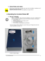
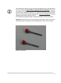
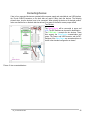
INHECO stackable devices Incubator Shaker MP Part No.: 7300013 Document Nr: 900237-001 User’s Manual Important: The device has to be in a level position at all times, it may not be tilted or turned upside down, especially not when the transportation screws are not in place! Revision level V1.5 BA_IncubatorShakerMP March 2012 1 INHECO Industrial Heating and Cooling reserves the right to modify their products for quality improvement. Please note that such modifications may not be documented in this manual. This manual and the information herein have been assembled with due diligence. INHECO does not assume liability for any misprints or cases of damage resulting from misprints in this manual. If there are any uncertainties, please feel free to contact us. The brand and product names within this manual are registered trademarks and belong to the respective titleholders. BA_IncubatorShakerMP 2 How to contact us: INHECO 82152 Martinsried Germany Telephone - Sales 089/899 593-101 Telephone – Technical Hotline 089/899 593-201 Fax E-Mail - Sales 089/899 593-499 [email protected] E-mail – Technical Hotline Website [email protected] www.inheco.com This manual belongs to Type Serial No. Year of Manufacturing: Order Confirming No. To be filled in by customer: Inventory No. Place of installation BA_IncubatorShakerMP 3 Important Notes Read this manual carefully before using INHECO stackable devices. In the following the names of the stackable devices, “Incubator Shaker” or “Incubator” are used. They represent one device of the “family” of stackable INHECO devices. Liability does not apply for mishandling the unit. This manual is part of the Incubator Shaker and must be retained until the Incubator Shaker is disposed of. passed on to the new user when the Incubator Shaker is sold or lent. Please contact the manufacturer in case you do not understand something within this manual. Your opinion about this manual provides us with valuable insights on how we can serve you better. Please do not hesitate to direct your comments to us, using the address or the phone numbers on page 3. Please read the safety instructions very carefully. They must be understood and observed in order to ensure safe handling of the unit. Missing or insufficient knowledge of the manual leads to loss of liability against INHECO. The operator should therefore ask for an instruction confirmation from the manufacturer to ensure proper handling of the device. BA_IncubatorShakerMP 4 CONTENT: 1. EXPLANATION OF SYMBOLS AND ABBREVIATIONS 7 1.1. ABBREVIATIONS 8 2. SAFETY INSTRUCTIONS 9 3. OPERATING INSTRUCTIONS 10 3.1. ABSTRACT 10 3.2. CONVENTIONAL USAGE 11 3.3. WHO IS PERMITTED TO OPERATE THIS UNIT? 11 3.4. SERVICING THE INCUBATOR 11 3.5. TECHNICAL ALTERATIONS 12 3.6. MALFUNCTIONS 12 3.7. NAME PLATES AND LABELS 13 4. 13 OPERATING THE INCUBATOR SHAKER MP 4.1. SCOPE OF SUPPLY 13 4.2. INITIAL OPERATION 14 4.3. USB COMMUNICATION 24 4.4. COMMUNICATION OF INCUBATORS TO THE USB HOST PC 25 4.5. COMMANDS 27 5. 28 TECHNICAL SPECIFICATIONS 5.1. TECHNICAL DATA 28 5.2. SHAKER FUNCTIONALITY 28 5.3. THERMAL FUNCTIONALITY 30 5.4. MODULE DIMENSIONS, WEIGHT 31 5.4.1 DIMENSIONS AND WEIGHT 31 5.4.2 DRAWER SPECIFICATIONS 32 BA_IncubatorShakerMP 5 6. FINAL QS TESTS 32 6.1. DRAWER TEST 32 6.2. PERFORMANCE TEST 32 7. CALIBRATION AND ADJUSTMENT 32 8. AUTOMATICALLY SELF TEST AQS 32 9. DETAILED DESCRIPTION OF THE ERROR CODES 32 10. TYPICAL PROCESS EXAMPLE 34 11. WARRANTY 34 12. POWER SUPPLIES 35 13. DECLARATION OF CONFORMITY 38 BA_IncubatorShakerMP 6 1. Explanation of Symbols and Abbreviations A possible danger, leading to serious bodily harm is being pointed out to you. Caution: hot surface ! A possible danger leading to less serious bodily harm is being pointed out to you. This signal also warns you of tangible damage. A possibly dangerous situation leading to material damage is being pointed out to you. Important! This sign refers to useful information as to installation etc. H i Bulletn points refer to enumeration. w e i s These arrows indicate instructions. The squares refer to procedures running automatically and the results to be achieved. BA_IncubatorShakerMP 7 1.1. Abbreviations The document uses the following terms: CC: Communication controller Controller: Microprocessor with on chip peripheral CRC: cyclic redundancy Check FCS: Firmware Command Set Heater: Same as Temperature Controller IVD(D): In vitro diagnostic (directive) MP: Micro Plate PCR: Polymerase Chain Reaction PWM: Pulse-Width Modulation Shaker: Controller for shaker regulation TBC: To Be Continued Temperature Controller: Controller for heat regulation USB: Universal Serial Bus CE: Conformity mark NRTL: Nationally Recognized Testing Laboratory DLL: Dynamic Link Library PC: Personal Computer EU: European Union SBS: Society for Biomolecular Screening DWP: Deepwell Plate IVD: In vitro diagnostics FDA: Food and Drug Administration DIP: Dual in line package BA_IncubatorShakerMP 8 2. Safety Instructions Avoid accidents. Always make sure that the unit is disconnected from the power supply system during any installation process. Electric Shock Hazard You can suffer an electric shock, if the unit is not connected properly or if you did not disconnect the unit from the power supply system before opening the housing. Please observe the following measures in order to avoid muscle convulsions, burns, unconsciousness, apnea or even death: Do not work with open housing when unit is connected to the power supply system. Always switch off the unit before implementing any alterations. The power supply is operated at a voltage of up to AC 240V. Burn Hazard You can burn your skin when touching the inner parts and especially the microplate contact surface and disposables. These parts can reach up to 85°C (185°F)! Do not use materials that are not sufficiently temperature resistant up to 110°C (230°F). Explosive, flammable and volatile materials may not be heated in the Incubator Shaker, at the risk of explosions! BA_IncubatorShakerMP 9 3. Operating Instructions 3.1. Abstract INHECO’s compact single position Incubators are high performance plug & play devices for the use on automated robotic platforms or as standalone units.. They can either be used as single devices or stacked in a tower. In addition multiple towers or single devices can be controlled parallel from one host PC via USB. The combination of different devices of the Incubator family in one tower is possible. Picture 1: Stacked Devices The patented shaker design allows shaking of several different shaking patterns with high precision in frequency and amplitude. The Incubators have built in safety features which enable them to be used in IVD and FDA applications (Technical Specification, chapter 5). The Temperature can be reported during processing to have a maximum of control. Precise temperature and shaker control, USB interface plate loading sensors and several self test routines guarantee a safe, precise and fast processing of probes. The Incubator Shaker is a state-of-the-art device for incubating SBS listed micro plates including flat bottom and PCR (with adapter plate). Service support is guaranteed through INHECO. BA_IncubatorShakerMP 10 3.2. Conventional Usage The Incubator Shaker is a state-of-the-art device and complies with today’s standards. The manufacturer attached much importance to the user’s safety. The following rules apply to the user: Rules of accident prevention General rules for technical safety EU and other country specific directives H The conventional usage contains the usage according to the manual. i n You must w be able to disconnect the main power supply to the instrument immediately if necessary. e i An unimpeded air supply must be ensured to avoid injuries to persons and/or damage to the s unit. Do not operate the Incubator Shaker MP above the maximum ambient temperature to prevent the Incubator Shaker MP from damage. Ensure that there is a minimum of at least 8cm ( 4 inches ) free space at the rear ventilation openings. The free space at the lower ventilation openings are accurately defined (3mm) by the positioning pins. 3.3. Who is permitted to operate this unit? Only instructed and skilled persons are permitted to operate this unit. Only specialized staff is allowed to make any amendments to the operating menu. H i 3.4. Servicing the Incubator n Run the wCommand AQS every 100h (see Chapter 8). Temperature e calibration may be checked and repeated regularly. Every 15000 operating hours or three years, whatever occurs first, an authorized INHECO i service technician should be check the device. s Calibrate INHECO recommends calibrating the Incubator device annually. H Cleaning i n Before cleaning the Incubator Shaker MP, disconnect the power and make sure that the w temperature at the heating plate is below +50°C. e surface should be cleaned regularly to ensure optimum heat transfer to the The contact H i Always clean the contact surface if there has been a spillage. Use the cloth disposable. i dipped ins 50:50 water / isopropanol solution and make sure that no deposits are left on the n surface. Care should be exercised to prevent water from running inside the unit. w e BA_IncubatorShakerMP 11 i s Do not use aggressive cleaning fluids such as acetone, or abrasive cleaners. Please check with INHECO any cleaning method that is not mentioned in it his paragraph to prevent damage to the Incubator Shaker MP. Decontamination The most common decontamination method is by fumigation with formaldehyde or ethylene oxide gas. The surface H decontamination can include a wipe-down of the housing surface. A solution of 70% alcohol should be used where effective for target organisms i The use nof Bleach (5%-12%) or Microside SQ is also possible. w e Repairi s The Incubator Shaker may only be repaired by authorized INHECO service technicians either locally or at INHECO’s. H i Shut down and Disposal n The unitwis to be disposed in accordance with the environmental directives in effect in the e country. respective i H s i Caution! n w The Incubator Shaker may only be operated in an upright and level position. e i The Incubator Shaker unit must not be stored below –10°C. Important s ! 3.5. Technical Alterations Important! Do not alter the product. For safety reasons no technical changes to this unit are allowed by unauthorized persons. Any modification or change, which is not approved by the manufacturer in written form leads to loss of warranty. The original parts are especially designed for the Incubator Shaker. Parts provided by other suppliers are not tested and therefore not approved by INHECO. Using such parts can impair the functionality of the unit and will lead to loss of warranty. For damages which may occur due to the usage of non original parts or non approved modifications or repairs, liability is excluded by INHECO. 3.6. Malfunctions Report occurring malfunctions immediately to the responsible person named on page 3 of this manual. Ensure that the unit is secured against violation and misuse. Before the initial operation, dismantled safety relevant parts have to be mounted and checked. BA_IncubatorShakerMP 12 3.7. Name Plates and Labels Please check all name plates and labels and ensure that their legibility is maintained at all times during the life time of this unit. Replace all name plates and labels if their legibility is no longer ensured. 4. Operating the Incubator Shaker MP 4.1. Scope of Supply Before initial operation, make sure that the shipment of your unit is complete and no parts are damaged. The following components should be included in each shipment: 1. Incubator Shaker unit 2. USB Cable between Incubator Shaker and PC 3. 15 pole SUB-D COM-Cable 4. CD or USB-Stick containing Manual and Software The Power Supply and Power Cable are not part of the scope of Supply, they have to be ordered separately (see chapter 12). 3 1 2 4 Picture 2: Scope of supply BA_IncubatorShakerMP 13 4.2. Initial Operation Transportation Picture 3: Transportation label at the upper side Picture 4: Transportation Lock at the bottom side BA_IncubatorShakerMP 14 Assembling / disassembling of transportation lock! H Turn Incubator Shaker MP slowly to the right (Attention! – Cover side in direction of assembler, like in picture) i n w e i s 1 2 4 3 5 Move A Picture 5: Assembling / disassembling of transportation lock (3 pieces)! BA_IncubatorShakerMP 15 Turn Incubator Shaker MP slowly to the left (Attention! – Cover side in direction of assembler, like in picture) 6 7 9 10 8 Move B Picture 5.1: Assembling / disassembling of transportation lock (3 pieces)! BA_IncubatorShakerMP 16 After unpacking the device, the two red screws (transportation lock) at the bottom side have to be unscrewed without tilting or turning the device upside down. Turning the unit upside down might require a renewal of the shaker drive calibration. Keep the screws for later transportation purposes. To install the transportation lock back again, Hdon’t turn the two screws too hard, just finger tight. Don’t use a screwdriver! This could idamage mechanical parts inside the device! nDo not dispose the original package, as it might be needed for further transportation. w eImportant: The device has to be in a level position at all times, it may not be tilted or iturned upside down, especially not when the transportation screws are not in place! s Picture 6: red Screws BA_IncubatorShakerMP 17 Mechanical Integration Place the device on an appropriate plate for a firm and even stand. Use the position pins on the bottom side for exact positioning of the device/stack. Important: It is not advisable to stack more than three devices on top of each other without additional mechanical fixation. Contact INHECO for more details. Important: The plate/device has to be in balance for proper shaker performance. Important: It is not advisable to stack more than three devices on top of each other without additional mechanical fixation. Contact INHECO for more details. H With this i method, it is possible to connect a maximum of four devices (one Master and three Slaves). n w e i s Picture 7: Details BA_IncubatorShakerMP 18 Important! The devices are built for the use with microplates. The Labware detection is optimized for Greiner Flat Bottom Plates. If different microplates are used, the user has to assure, that the Labware detection works well with these plates too. Light master plates are better than dark ones Master plates with matt surface are better than shiny ones Attaching an adapted tape on the left side of the master plate improves the success rate of the Labware detection. With the command ASE1 the incubator shaker is unable to shake without detected Labware. The command ASEND has been added to enable shaking without detected Labware. We do not recommend using it! The command ASE1 is preferred. It ensures that the Labware is correctly placed on the shaker and performs within the specifications. The bottom of the microplates must be flat to ensure uniform heat exchange. If the customer prefers plates with different shaped bottom, a special adapter is needed. INHECO offers to design and manufacture a customized adapter. The devices can measure the temperature at the top of the heat plate only. The temperature of the liquid in the microplate differs from this. Therefore a heater offset must be defined and set before the temperatures in the liquid samples are correct (see also command SHO). After Cmd AID for Initialization is send to the Incubator Shaker, the door will close, if it was open. If the door was already closed, a short buzzing sound can be heard. When a microplate is put on the drawer and the door is being closed, the microplate will be clamped on the drawer. When the drawer reaches its end position inside the Incubator Shaker, the microplate will be sinking on the heat plate for best thermal contact. You can hear a short shaking noise to ensure, that the microplate is sinking on the heat plate but only when the microplate is detected correctly from the device. The heat plate has three integrated sensors for measuring the temperature. The temperature of the sensors is averaged. BA_IncubatorShakerMP 19 Electrical Details General The device needs an electrical power supply that provides a stable 24Vdc voltage. The power consumption for one device is max. 2 Ampere (50 Watt). If more devices are stacked, the power supply must be able to deliver the resulting power consumption. The polarisation at the power connector at the back side is shown in the following picture. The red wire symbols the “plus-pole” and the black the “minus-pole”. To communicate with the device, a computer with an USB-Connection is necessary. The USB-Connector is placed at the back side (see blue mark at picture 8). Picture 8: Standard connection for one device BA_IncubatorShakerMP 20 Address-Switch A six-pole DIP-Switch can be found at the back side. Only the switches 1 to 4 are used for setting the address. These switches are for identification, if more than one single-device or stack is connected to the PC. The default address is “2”. The recognition of the device/stack depends on the switches position as shown in picture 9. Picture 9: Address-Switch BA_IncubatorShakerMP 21 Connecting Devices If two to four connected devices are operated with one power supply and controlled via one USB interface, the 15-pole SUB-D-Connectors on the back side are used to daisy chain the devices. The following pictures show, how the devices have to be connected. When placing the device at its desired position, make sure that the fan on the back side has at least 3 cm space to the wall to ensure proper airflow! Two Devices The Master-Device will be connected to power and USB. The DIP-Switches can be used for identification. The COM-Cable 1 connects the two devices. These lines support the Slave-Device communication and power. The Power- and USB-Connector and the DIPSwitches of the Slave-Device are unused and have to be left in the standard configuration as shown! Picture 10: two connected devices BA_IncubatorShakerMP 22 Three Devices: The Master-Device will be connected to power and USB. The DIP-Switches can be used for identification. The COM-Cables (green 1 and blue 2) connect the three devices. These lines support the Slave-Devices communication and power. The Power- and USB-Connector and the DIP-Switches of the Slave-Devices are unused and have to be left in the standard configuration as shown! Picture 11: three connected Devices BA_IncubatorShakerMP 23 Four Devices: The Master-Device will be connected to power and USB. The DIP-Switches can be used for identification. The COM-Cables (green 1, blue 2 and orange 3) connect the four devices. These lines support the Slave-Devices communication and power. The Power- and USB-Connectors and the DIPSwitches of the Slave-Devices are unused and have to be left in the standard configuration as shown! Picture 12: four connected devices 4.3. USB Communication Hard- and software features of the Incubator USB virtual COM port are specified in this section. Remark: The USB is not optimized for secure real time data transfer. Therefore all communication is secured by a cyclic redundancy checksum (crc). If the communication between the PC and the MTC does often fail or results in timeouts, in most cases the PC is causing the problem. . Therefore we recommend for a robust communication the following: 1. Other devices connected to the USB might have an influence on the communication stability of the incubator 2. Use a simple workstation PC 3. The stability of the communication has to be verified with every PC 4. Windows 7 and Vista seems to be more stable than Windows XP 5. Do not activate the automated update from Windows BA_IncubatorShakerMP 24 4.4. Communication of Incubators to the USB Host PC Our recommendation for Incubator Shakers is to use it in three floor stacks. For details see section 4.2. For the example on hand we want to use a more complicated configuration: Five devices daisy chained with the D-Sub-D connectors (Two power supplies are needed, one for two and one for three devices). Two devices in one stack One single device A second single device The LED indicates the status of the module: Power on and device is initialised >> LED on Firmware download >> LED is blinking (ca. 3-5 Hz) USB-Communication not present >> LED is blinking (ca. 1 Hz) Details shown in the picture below D-Sub USB TT11 T TT30 TT26 TTxy TT20 T TTT48 T 3 T 0 2 6 TT28 T T 2 0T T 4 8 TT27 T T TT09 2 T 8 2 7 Incubator with serial number T TTxy T x y TT05 T T x y Picture 18: Interconnection BA_IncubatorShakerMP 25 T T 0 5 The starting basis is as follows: 1. 2. 3. 4. 5. USB drivers installed on the PC The PC is connected to the bottom Incubator of a stack via USB. The INHECO tool is installed on the PC All COM ports are closed. All Incubators are daisy chained power is switched on on and they are connected to the PC. After pushing the button “Find Incubators @ COM Ports”, all COM Ports will be scanned and some commands of the Firmware Command Set will be automatically executed to determine the configuration. The results will be written into the textbox of the tool and the combo boxes for COM port and device ID will be set respectively. In more detail: 6. 7. 8. 9. 10. 11. 12. 13. 14. 15. 16. 17. 18. 19. Find out all available COM ports1. Open next available COM port. If none go to 18. Send an arbitrary command for “synchronisation and announcement”. If no reply Close COM port and go to 7. Else (important): Look if a device ID error is present and look at the reply (this is working since firmware version CC 3.17). Device ID of that stack (master device). Send RDA0,1 to the master on this COM Port with the device ID found. Number of floors (# Slave devices). Send RFV2 to the master and all its slave devices (take care of the floor ID, T00 T01 T02 …) up to the number of slave devices. Store serial numbers, COM port name, number of devices and device ID. Close the COM port. Go to 7. Write the results to the textbox and fill the combo boxes of device ID and COM port name and the tabs accordingly. Finished (see picture 16 for the result). Now you are able to open four COM ports. Just click at Open COM on the four tabs. For the implementation it is important to consider different setup conditions. Some devices may be already connected to the USB (green LED is on) some may not (green LED is blinking at 1 Hz). The blinking of the LED stops only after the first message with the correct device ID is sent to the Incubator device. Therefore you need to send at least two messages to bring all devices into the same state. The reason for that is that slave devices have to register themselves to the master device within a certain time frame. This happens after the first correct USB message to the master was sent. If you have used for example a USB Bluetooth adapter on your PC, Windows sometimes creates lots of COM ports for this purpose. If you plan to use that PC to control Incubators we recommend deleting all these COM ports first. 1 BA_IncubatorShakerMP 26 Picture 20: Application Example The COM ports may change therefore pleas use the device ID to have a unique identification of a stack. Parallel communication to different COM ports is possible. Parallel communication with different members of one stack is forbidden and may result in errors. 4.5. Commands All commands for the integration of the single Incubator are described in the document “Incubator FCS /Document NR: 900334-XXX”. BA_IncubatorShakerMP 27 5. Technical Specifications 5.1. Technical Data Incubator Shaker Limits for ambient operating temperature Input voltage Input current (Power) Temperature range Tolerable relative humidity ambient Maximum load of the shaker platform Shaker frequency range Maximum shaking amplitude Shaking direction Storage conditions Length x Width x Height Weight including cables # of devices in one stack Technical Data +15°C to +30°C [+59°F to +86°F] 24Vdc 2A (50W) max. Room temperature plus 5K to +80°C [+176°F] 10-80% relative (non condensing) at +30°C [+86°F] or below 0,25 kg 6,6 Hz to 30 Hz → 400 rpm to 1800 rpm 3 mm (difference between the maxima) Arbitrary -10°C to +60°C [+14°F to +140°F], non condensing See chapter 5.4 4.7 kg Maximum three due to interaction during shaking 5.2. Shaker Functionality Parameter Value 0.0 – 3.0 mm* Amplitude range * For detailed shaker performance, see chapter below. 6.6 – 30.0 Hz* Speed range * For detailed shaker performance, see chapter below. Speed precision ±2 Hz (weight of plate and liquid and adapter) 40 – 250g* Load * For detailed shaker performance, see chapter below. Supervision speed and amplitude (closed loop controller) North – South East – West Shaker movement Round “Eight” Amplitude accuracy** ±15% (of the target amplitude) ±11° Shaker movement Phase shift accuracy** ** validated for the Heating Plate movement / average value over 10 cycles BA_IncubatorShakerMP 28 Single Axis (North – South and East – West) Shaker Load: 100g Shaker amplitude [mm] Shaker Speed [Hz] 10 15 20 Round (Phase shift = 90°) Single Device Triple Stack X = 1.0 to 2.2 X = 1,0 to 1.9 or or Y = 1.0 to 2.2 Y = 1.0 to 1.9 X = 1.0 to 2.7 X = 1.0 to 2.4 or or Y = 1.0 to 2.7 Y = 1,0 to 2.4 X = 1,0 to 1.2 X = 1.0 to 1.2 or or Y = 1.0 to 1.2 Y= 1.0 to 1.2 Shaker Load: 100g Shaker amplitude [mm] Shaker Speed [Hz] Single Device Triple Stack 10 X = 1.0 to 2.2 Y = 1.0 to 2.2 X = 1,0 to 1.9 Y = 1.0 to 1.9 15 X = 1.0 to 2.7 Y = 1.0 to 2.7 X = 1.0 to 2.4 Y = 1.0 to 2.4 20 X = 1.0 to 1.2 Y = 1.0 to 1.2 X = 1.0 to 1.2 Y = 1.0 to 1.2 X Y X shaker table X Y door s shaker table h a d door k o e o r r t a b l e BA_IncubatorShakerMP 29 5.3. Thermal Functionality Parameter Temperature range Accuracy absolute (@ ambient temperature stability ±1K) Uniformity measured in well Evaporation in unsealed Micro Plates Value Room temperature plus 5K to +80°C [+176°F](only for shaking for one hour) Check the internal Sensors of the Incubator. Room Temperature plus 10K to +80°C [+176°F](for shaking longer than one hour) The accuracy is defined as the difference between the target temperature of the heating plate and the average of the measured temperature on the heating plate. The heating plate temperature is measured at 5 positions on the heating plate according to the INHECO measurement head PM-0105. The 5 measurement positions are according to the Plate positions A1, H1, E6, A12 and H12. Target Temp. Validation Tool Accuracy [°C] +20°C [+68°F] ±1 +37°C [+98,6°F] ±1 +60°C [+140°F] ±1.5 +80°C [+176°F] ±2 Uniformity is defined by the maximum difference between lowest and highest temperature according to a IMP(INHECO Measurement Plate) Target Temp. Validation Tool Uniformity [°C] +37°C [+98,6°F] ≤ ±0.9 +60°C [+140°F] ≤ ±1,4 +80°C [+176°F] ≤ ±1,8 Incubator temperature +37°C [+98, 6°F], max. 32% loss of liquid in 4 h, deionized water, room temperature 24-26°C [75,2-78,8°F], rel. humidity 4050%, altitude at 410 m over Sea level. INHECO recommends to seal or cover the microplates with a lid to avoid cross-contamination and evaporation Heatup time BA_IncubatorShakerMP Start temperature +15.6°C [+60°F]; Target temperature +37 °C [+98,6°F]; Heat up time max.30min; Volume 280µl per well. The target temperature is reached when all sensors are in the tolerance band of 37°C ±1°C [98,6°F ±3,6°F] Measured with: 1) Greiner Flat Bottom Plate #655076 with 4 sensors (A1, H1, E7,H12) 30 5.4. Module Dimensions, Weight X m o d u l e Picture 21: Dimensions 5.4.1 Dimensions and Weight Parameter Dimension of thermal chamber in ZChamber Value 149 mm 1) 268,5 mm without connector cables 2) 298,5 mm with connector cables 87 mm (Incubator Shaker) 209 mm 23,5 mm Weight (without cables) 4.5 kg (Incubator Shaker) Dimension in XModule Dimension in YModule Dimension in ZModule (without pin) Open drawer incl. door YDrawer BA_IncubatorShakerMP 31 5.4.2 Drawer Specifications Parameter Accuracy of the end position of the drawer in x, y and z (drawer open); single unit, all parts at specified ambient temperature Value Maximum Drawer load 0,25 kg Open drawer resistance for a force in Z-axis without plastic deformation 10 N ±0,30 mm 6. Final QS Tests All units, which leave INHECO, have to pass through three semi-automatic test procedures. 6.1. Drawer Test The device must pass at least 100 drawer cycles with correct Labware detection without error. 6.2. Performance Test Finally all important functions are tested and the self test AQS (see chapter 8) must run without error. 7. Calibration and Adjustment The adjustment of the shaker and/or the calibration of the temperature are done at INHECO. Settings are stored into the devices EEPROMS and redundant in an INHECO Database. A redundant check of all data is done. 8. Automatically self test AQS The automatically self test AQS is performing several tests to ensure proper functionality of the device. After the tests are finished, the device generates an error code (see Firmware Command Set). These tests are: Drawer Test: Checks opening and closing of the drawer. Shaker Test: Tests timing, amplitudes and frequencies of different settings Temperature Test: Tests timing and homogeneity of the heating procedure including boost. Duration: 3 min. 30 sec. 9. Detailed description of the Error Codes The error codes embedded into the message reply are mainly meant to give the user additional information about the status of the device. The reply to every command ends always with the following three hex data: 0xB0+device ID: This ensures that it is a reply from the device with this device ID. 0x20-error code: BA_IncubatorShakerMP 32 The following table 1 describes the error codes (see also Firmware Command Set): Table 1: error codes Code Error message 0 1 Message Ok Reset detected 2 Invalid command 3 Invalid operand 4 Protocol error 5 Timeout from device 6 Device ID error 7 Device not initialized 8 Command not executable 9 10 Drawer not in end position Unexpected Labware Status 11 12 13 14 Reserved Reserved Reserved Floor ID error 15 Timeout sub device Detailed description Normal return message. Power on, software or watchdog reset. Three kinds of resets are possible: i) Power on reset after the first ordinary message reply after power on this error code will be send. This is a correct behaviour ii) Software reset after the command SRS the green led in front of the device blinks shortly. The software reset brings the device into the same state after power on. Therefore also here this error code will be send. iii) Watchdog reset if the firmware runs into trouble in most imaginable situations a watchdog reset occurs. This error code will be send. Please inform the INHECO Tec-hotline in such a case. The Command does not exist for this device. This flag is set if the command is completely unknown. E.G if a shaker command has been sent to an Incubator without shaker function. Parameter out of range (see command set). This error code will be reported, if the Parameter of a correct command is out of range. E.G. SAX307 USB Protocol error. Wrong message length or CRC. The USB Message is secured by a cyclic redundancy check at the last byte of a message. If the last byte is incorrect or missing this error code will be reported. Device did not answer within the expected time frame. This error must be generated by the PC application The device ID can be changed at the dip switch on the rear side of the device. If the message one sends to this device has the wrong device ID this error is replied. Command requires prior initialization of a sub system. E.g. It is not possible to open the drawer or to shake the Labware of a non initialised device. Parameter or device condition prohibits execution. The typical example is that no Labware has been detected and the user tries to shake using the command ASE1. The drawer is in an unknown position (generated by RDS). E.G. the door is blocked A Labware is detected on AOD after a power-up or after an undefined drawer status. Device is not registered in the master. E.G. A command has been send to the slave device with ID 2, but only one slave is connected to the master. The error message is from this device. The sub devices, heater or shaker did not answer within the expected time frame. The Incubator Shaker has three µCs. The heater and the shaker controller work as a kind of sub devices of the communication controller. If the inter µC communication is corrupted this error code will be reported. Most error codes can be used for a PC lab automation application to generate its own error codes or to change automatically its operation status. E.G. if the device ID error is reported the device ID must be changed. Ox60: End of reply BA_IncubatorShakerMP 33 10. Typical process example A typical cycle for a process should contain the following steps: Scan COM Ports Find device ID, # slaves and serial number of all connected devices Check the number of drawer cycles and the firmware versions of all devices Initialize all devices Open doors simultaneous or sequential Put in the Labware and the adapter if necessary Set target temperature for each Incubator Set heater offset according to the used type of micro plate Set frequencies, amplitudes and phase shift for all devices Close the doors Start shaking Start heating Check cyclic temperatures, frequencies, amplitudes and the error flags Optional change target temperature Optional restart heating Optional change frequencies etc. Optional restart shaking Stop shaking and heating Open all doors 11. Warranty 2 Years from date of shipment. Any damage by abuse or caused by operation different from this instruction is not covered. BA_IncubatorShakerMP 34 12. Power Supplies The Power Supplies can be ordered separately at INHECO. Picture 22: Power Supply built for 1 and more incubators Power Supply built for 1 and more incubators AC Input: 100-240V / 2,5A / 50-60 Hz DC Output: 24V / 7,5A Part #: 2400121 Picture 23: U.K. Power Supply Cord set Part #: 1004214 BA_IncubatorShakerMP 35 Picture 24: European Power Supply Cord set Part #: 1004184 Picture 25: North-American Power Supply Cord set Part #: 1004185 BA_IncubatorShakerMP 36 Table 2: Version Management VERSION NO RELEASE DATE 1.0 July 2009 1.1 February 2010 1.2 1.3 1.4 February 2010 February 2010 April 2011 1.5 March 2012 BA_IncubatorShakerMP CHANGES TO PRIOR VERSION Abbreviations p.8; Cleaning p.11; Technical data p.32 Technical data p.32 Dimensions p.35 Overworked assembling of transportation lock system p.13-16 Power supply Part #: 2400122 canceled p.39, only one power supply Part #: 2400121 for 1 and more incubators Updated Pictures Redesign of Document 37 13. Declaration of Conformity INHECO GmbH 82152 Martinsried Germany Declares that the following product: Incubator Shaker MP Meets the essential requirements of the following European Union Directive(s) using the relevant section(s) of the normalized standards and related documents shown: Standard and Date of Issue IEC 61010 – 1 : 2001 (2nd Edition) EN 61010 – 1 : 2001 (2nd Edition) EN 61010-2-010: 2004 EN 61000-3-2 EN 61000-3-3 EN 61326-1: 2006 Safety requirement for electrical equipment for measurement, control and laboratory use. Particular requirements for laboratory equipment for the heating of materials. Electrical equipment for measurement, control and laboratory use. EMC requirements. Electrical equipment for measurement, control and laboratory use. EMC requirements. This product is in complies with the essential requirements of the Low Voltage Directive 73/23/EWG and EMC directive 2004/108/EC, when used for its intended purpose. Place Date Martinsried/ Munich March 2012 Signature Name, Position Günter Tenzler, Managing Director BA_IncubatorShakerMP 38