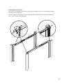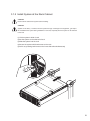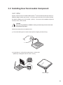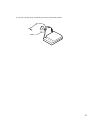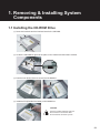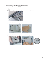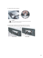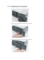
1
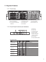
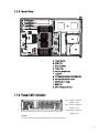
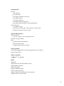
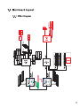
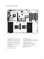
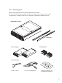
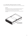
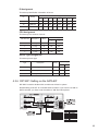
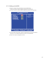
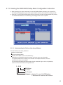
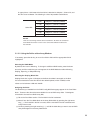
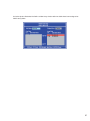
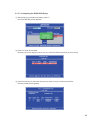
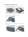
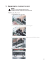
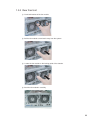
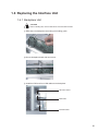
3326
Rev 1.4
CONTENTS
Part I. User's Guide
Preface
3
1. Introduction
4
1.1 System Feature
5
1.1.1 Front View
5
1.1.2 Front Panel Controls and Indicators
5
1.1.3 Rear View
6
1.1.4 Inner View
7
1.1.5 Power LED Indication
7
1.2 System Specifications
1.3 Mainboard Layout
8
1.3.1 Block Diagram
11
1.3.2 Mainboard Layout
12
11
2. Important Safety Information
13
3. System Installation
16
3.1 Preparing for Setup
16
3.1.1 Unpacking
16
3.1.2 Packing List
17
3.1.3 Environmental Specifications
18
3.1.4 Install Rail for Mounting the System on the Rack
19
3.1.5 Install System at the Rack Cabinet
21
3.2 Installing User Serviceable Component
22
3.2.1 CPU
22
3.2.2 Memory
24
3.2.3 Hard Disk Drives
29
3.2.4 PCI Add-on Cards
30
3.2.5 Power Module Hot Plugging
31
4. BIOS and Jumper Setup
4.1 BIOS
32
32
4.1.1 Starting BIOS Setup
32
4.1.2 Updating BIOS Setup
33
4.1.3 Using Setup
34
4.1.4 Main Menu
35
4.1.5 Advanced Menu
36
4.1.6 PCI PnP Menu
46
4.1.7 Boot Menu
48
4.1.8 Security Menu
49
1
CONTENTS
4.1.9 Chipset Configuration Menu
52
4.1.10 Power Menu
56
4.1.11 Exit Menu
57
4.2 Jumper Setting
59
4.2.1 PCI-X Speed Setting(J22, J26)
60
4.2.2 VGA Enable / Disable(J18)
60
4.2.3 Clear CMOS Header
61
4.2.4 Geographical ID Setting
61
4.2.5 DIP SW1 Setting on the SATA BP
62
5. Software & Utilities
5.1 NVRAID
5.2 Adaptec SCSI with HostRAID(Optional)
5.3 ServerDome
63
63
73
83
Part II. Technical Guide
1. Removing & Installing System Components
1.1
1.2
1.3
1.4
1.5
84
Installing the CD-ROM Drive
Installing the Floppy Disk Drive
Installing the Hard Disk Drive
Removing the Power Supply Unit
Replacing the Cooling Fan Unit
84
1.5.1 Center Fan Unit
89
1.5.2 Rear Fan Unit
90
1.6 Replacing the Interface Unit
85
87
88
89
91
1.6.1 Backplane Unit
91
1.6.2 Interface Board(IFB) Unit
92
1.6.3 Center FAN Cage Unit
92
1.6.4 SCSI Cable
93
1.7 Installing the Motherboard
1.8 Installing the Rear Cage Unit
1.9 Installing the Heatsink
1.10 Installing the Air Duct
1.11 Installing the Front Bezel
94
95
96
96
97
Appendix
A BIOS Post Code
98
2
Part I.
User's Guide
Preface
The information in this User's Guide has been carefully reviewed and is believed to be accurate.
The vendor assumes no responsibility for any inaccuracies that may be contained in this document, makes no
commitment to update or to keep current the information in this Guide, or to notify any person or organization
of the updates.
NOTE: For any up-to-date version of this document, please see our web site at www.appro.com.
Appro International, Inc. reserves the right to make changes to the product described in this manual at any
time and without notice. This product, including software, if any, and documentation may not, in whole or in part,
be copied, photocopied, reproduced, translated or reduced to any medium or machine without written consent.
Copyright Notice
The material in this document is the intellectual property of Appro International, Inc. We take every care in
the preparation of this document, but no guarantee is given as to the correctness of its contents.
Our products are under continual improvement and we reserve the right to make changes without notice.
Technical Support
If a problem arises with your system and no solution can be obtained from the user's manual, please contact your
place of purchase or local distributor. Alternatively, please try the following help resources for further guidance.
Visit the Appro website for FAQ, technical guide, BIOS updates, driver updates, and other information:
http://www.appro.com/ and http://red.appro.com/Public/XtremeServer/
Contact our technical staff at: http://www.appro.com/supports/main.asp
Revision History
Revision
Revision History
V1.4
Date
Fourth release
April 2006
3
1. Introduction
The key objective for XtremeServer is to overcome the major challenges faced by developers, and system integrators
alike, in deploying ideal server solutions to the market. Although many, key challenges are identified as reliability,
performance, value, scalability and manageability. XtremeServer offers the best in class for each of these challenges
by employing the latest technology designed by a specialized sever team.
The XtremeServer 3326 3U Rackmount Server is a high-performance barebone system powered by
Dual AMD OpteronTM Processors, nVIDIA nForce Professional 2200 & 2050, AMD 8132 PCI-X Tunnel chipset,
ADM1026 Hardware Monitoring Chip.
In addition, 8 DIMM sockets are supported per CPU. This first-in-industry feature increases the performance/value
mix by reducing the cost of system memory by up to 100% over competition.
In line with extreme processing and data buffering capability, XtremeServer is equipped with both PCI-Express and
PCI-X slots and SATA II with RAID 0, 1 support. For those preferring SCSI devices, dual U320 SCSI channel with
RAID option is available. Data transfer is optimized with on-board dual PCI-Express Gigabit Ethernet ports.
Server management feature is unrivaled by utilizing its dedicated BMC with IPMI 2.0 based ServerDome.
A remote management suite handles all aspects of deployment, management and monitoring of XtremeServer
at an individual or aggregate level. Last but not least, XtremeServer is cable-less and tool-less integration.
This well thoughtout packaging keeps all variations of XtremeServer ultra cool and easy to maintain, thus, optimizing
on reliability and TCO.
4
1.1 System Feature
1.1.1 Front View
g
a
g
c
b
f
d
e
d
a. Slim CD-ROM Drive
c. FDD Ejector button
f. Mounting Bracket
b. Front Panel Controls and
Indicators
d. Hard Disk Drive
g. Bracket Slide Inner
f
e. Front Bezel
1.1.2 Front Panel Controls and Indicators
a. USB Ports
a
b c d e f
g h
b. Power LED
c. LAN Activity LED
d. System ID LED
e. System Fault LED
f. System ID Switch
g. Reset Switch
h. Power ON/OFF Switch
Front Panel LEDs
System Power
LAN1/LAN2 Activity
System ID
System is turned on
System is off
Network is linked and accessed
No LAN access
Identification is active by management
software
Identification is not active
System Fault
HDD Status
HDD Activity
Running/normal operation
Critical or non-recoverable condition
HDD exists and is powered
No HDD
Disk is accessed
No disk activity
5
1.1.3 Rear View
k
l
l
a
b
c
d
e f g
h
i
a. PCI Slots
g. IEEE 1394 Port
b. System Geographical ID Switch
h. GbE LAN Port(IPMI)
c. VGA Port
i. GbE LAN Port
d. Serial Port
j. External SCSI Port
e. PS/2 Port(Keyboard & Mouse)
k. AC Power Inlet
f. USB 2.0 Ports
l. Rear Fan
j
LAN Port Function
The LAN port uses a CAT 6 LAN cable for connecting the motherboard to a local area
network by means of a network hub. The port has 2 indicator LEDs.
LAN is linked and accessed
Link and Activity
LAN is not linked
Orange
Speed
Gigabit mode access
100Mbps mode access
10Mbps mode access
Link and Activity LED
Speed LED
6
1.1.4 Inner View
g
h
a
i
e
k
j
f
d
b
f
j
d
c
e
a. Power Supply
b. Silm FDD
c. Silm CD-ROM
d. Center Fan
e. Memory DIMM Slots
f. Heatsink
g. PCI-Express Add-on Card(Optional)
h. PCI-Express Add-on Cards
i. PCI-X Add-on Cards
j. Rear Fan
k. CPU / Memory Air Duct
1.1.5 Power LED Indication
AC: Green - Normal
AC
Yellow - Fail
DC
FAN
DC: Green - Normal
Yellow - Fail
FAN: Green - Normal
Yellow - Fail
NOTICE
You can check the power status LED after the front bezel is removed.
7
1.2 System Specifications
Processor
Dual mPGA 940-pin ZIF sockets
Supports up to 2P/4C Dual-Core AMD OpteronTM 800 Series processors
Integrated 128bit DDR memory controller
Chipset
NVIDIA nForceTM Professional 2200
AMD-8132TM PCI-X 2.0 Tunnel
NVIDIA nForceTM Professional 2050 (3326VA-01)
Winbond Super I/O chip
Analog Devices hardware monitoring chip
Memory
128-bit dual channel memory bus
Eight DIMMs per CPU, up to 64GB memory capacity
Registered ECC DDR400/333/266 SDRAM DIMM
SATA Controller (3326VA-01)
Integrated nForceTM Professional 2200 and 2050
Six ports supporting RAID 0, 1, 0+1
SCSI Controller (3326ES-01)
Adaptec AIC-7902W dual channel U320 SCSI controller
1CH shared with External SCSI port
Adaptec HostRAID
IDE Controller
Integrated nForceTM Professional 2200
One port for CD-ROM Drive
2.5" HDD (optional)
Drive Bays
Supports six hot-swap SATA HDD (3326VA-01)
Supports six hot-swap U320 SCSI HDD (3326ES-01)
Supports Slim CD-ROM and Slim FDD Drive
Expansion Slots
Two x16 PCI-Express slot supporting full-length add-on card
One x4 PCI-Express slot supporting half-length add-on card
Two 64bit 133/100/66MHz PCI-X slot supporting half-length add-on card
One 64bit 133/100/66MHz PCI-X slot supporting full-length add-on card
8
Integrated I/O
Rear I/O
One VGA port
One serial port
One PS/2 keyboard & mouse port
Two USB 2.0 ports
Two RJ45 GbE ports
One IEEE-1394a (Firewire) port
One VHDCI external SCSI connector (3326ES-01)
Front LED Panel
Two USB 2.0 ports
LEDs: Power / GbE LAN1 / GbE LAN2 / ID / System Fault
Switches: System ID / Reset / Power
System Management
FAN connectors
For CPU / System - Two step speed control
Port 80h 7 segment display
BMC
Supports IPMI 2.0 specification
Auto fan speed control
Voltage and fan speed monitoring
LAN Controller
Two Broadcom BCM5721 PCI-Express gigabit ethernet controllers
Support PXE function
Video Controller
ATI RAGETM XL with 8MB
BIOS
AMI BIOS
Support ACPI 2.0 with S0/S1/S3/S4 and S5
Support AMD PowerNow!
48-bit LBA support
Support USB K/B & Mouse
Serial Console Redirection
Support USB boot and PXE boot in boot sequence
Support serial over LAN function
9
Power Supply
1000W(2+1) hot-swap redundant Power Supply with PFC function
AC Input: 100-240 VAC at 50/60 MHz; 8-4A
Form Factor
3U (H x W x D): 131 x 430 x 698 mm (5.2 x 16.9 x 27.5 inch)
Regulatory
CE(EMC) : EN55022(EMI), EN55024(EMS), EN61000-3-2(Harmonic), EN61000-3-3(Flicker)
CE(LVD) : EN60950
CB : IEC 60950
FCC : FCC 15 Subpart A
UL : UL 60950
MIC : KN22(EMI), KN24(EMS)
10
1.3.2 Mainboard Layout
14
11
11
BROADCOM
13
BROADCOM
13
16
12
10
6
inbond
8
9
8
9
8
15
17
4
5
UNIWIDE
1
3
① AMD OpteronTM Socket 940 - CPU0
② AMD Opteron
TM
Socket 940 - CPU1
③ Registered ECC DDR memory slots
④ NVIDIA nForce
TM
Professional 2200
7
2
3
⑩ PCI Express x4 slot
⑪ Two Broadcom PCI Express GbE ports
⑫ Adaptec AIC-7902W SCSI Host Adapter
⑬ 68P SCSI Connector
⑤ NVIDIA nForceTM Professional 2050
⑭ VHDCI External SCSI Connector
⑥ AMD 8132 PCI-X 2.0 Tunnel
⑮ Winbond 83627THF LPC Super I/O
⑦ HT Connector
ATI Rage XL Video Controller
⑧ PCI-X 64bit/133MHz slots
Interface Connector
⑨ PCI Express x16 slot
12
2. Important Safety Information
Only a technically qualified person shall access, integrate, configure, and service this product.
To avoid personal injury or property damage, read, observe, and adhere to all of the following safety instructions
and information before you begin installing the product.
2.1 Intended application uses
This product was evaluated as information technology equipment (ITE), which may be installed in offices, schools,
computer rooms, and similar commercial type locations. The suitability of this product for other product categories
and environment (such as medial, industrial, alarm systems, and test equipment), other than an ITE application,
may require further evaluation.
2.2 Checking the power cord
CAUTION
To avoid electrical shock, check the power cord(s) that will be used with the product:
Do not attempt to modify or use the AC power cord(s) if they are not the exact type required.
If a power cord is not compatible with the AC wall outlet in your region, get one that meets the following criteria:
The power cord must be properly rated for the AC voltage in your region.
The power cord plug cap must have an electrical current rating that is at least 125% of the electrical current
rating of the product.
The power cord plug cap that plugs into the wall socket-outlet must have a grounding type male plug designed
for use in your region.
The power cord must have safety certifications for your region, and shall be marked with the certification
markings.
The power cord plug cap that plugs into the AC receptacle on the power supply must be an IEC 320, sheet C13,
type female connector.
In Europe, the power cord must be less than 4.5 meters (14.76 feet) long, and it must be flexible <HAR>
(harmonized) or VDE certified cordage to comply with the chassis' safety certifications.
The power supply cord(s) is the main disconnect device to AC power.
The socket outlet(s) shall be near the equipment and shall be readily accessible for disconnection.
13
2.3 Earth-grounded socket outlets
CAUTION
To avoid electrical shock, the system power cord(s) must be plugged into socket-outlet(s) that is provided with
a suitable earth ground. The system will be provided with the following marking:
Connect only to properly earthed socket outlet.
2.4 Before you remove the access covers
CAUTION
To avoid personal injury or property damage, the following safety instructions apply whenever accessing inside
the product:
Turn off all peripheral devices connected to this product.
Turn off the system by pressing the power button on the front of the product.
Disconnect the AC power by unplugging all AC power cords from the system or wall outlet.
Disconnect all cables and telecommunication lines that are connected to the system.
Retain all screws or other fasteners when removing access cover(s). Upon completion of accessing inside
the product, refasten access cover with original screws or fasteners.
Do not access inside power supply. There are no serviceable parts in the power supply.
Return to manufacturer for servicing.
2.5 Fans
CAUTION
To avoid injury, do not contact moving fan blades.
2.6 Electrostatic discharge (ESD)
CAUTION
Perform the procedures in this product guide only at an electrostatic discharge (ESD) workstation, because the
server components can be extremely sensitive to ESD. If no such station is available, you can reduce the risk of
electrostatic discharge ESD damage by doing the following:
Wear an antistatic wrist strap and attach it to a metal part of the server.
Touch the metal on the server chassis before touching the server components.
Keep part of your body in contact with the metal server chassis to dissipate the static charge while handling
the components.
Avoid moving around unnecessarily.
Hold the server components (especially boards) only by the edges.
Place the server components on a grounded, static-free surface.
Use a conductive foam pad if available but not the component wrapper.
Do not slide the components over any surface.
14
2.7 Cooling and Airflow
CAUTION
For proper cooling and airflow, always install all access covers before turning on the system.
Operating the system for longer than five minutes without the covers in place can cause overheating and
damage to system components.
2.8 Battery
CAUTION
Risk of explosion if battery is replaced by an incorrect type.
Dispose of used batterries according to the instructions.
15
3. System Installation
3.1 Preparing for Setup
3.1.1 Unpacking
① Main Box
② Slide Rail Box
③ Heatsink Pad
④ Heatsink Box
10
9
⑤ System Bottom Cushion
⑥ XtremeServer 3326 System
⑦ System Top Cushion
⑧ Accessory Box
⑨ PSU Box
8
7
⑩ Power Supply Unit
6
5
4
3
2
1
CAUTION
In setting the product out of the box, hold it in the middle and not the cushion.
Depending on the weight of the product, two people together should lift it.
16
3.1.2 Packing List
Unpack the package and check if all items listed below are present.
If any item contained in the package is damaged or missing, please contact your local dealer
for replacement. In addition, keep the box and packing materials for possible future use.
XtremeServer 3326
Slide Rail
Power Supply
CPU Heatsink
Accessory Box
1
2
3
4
① PS/2 Y-Cable
② Power Cord(Optional)
③ Manual and Driver CD
④ ServerDome(Optional)
17
3.1.3 Environmental Specifications
Place
In front of the system, minimum 25" of the space is needed for using and managing the system.
In rear of the system, minimum 30" of the space is needed for managing the system and airflow.
Power supply
Before installing the system, check the power capacity of the place where the system is installed.
Grounding
The system should be grounded.
Temperature
The system should be installed where the airflow and temperature is proper.
If the system is installed in the rack, the temperature in rack should be less than 35 degree Celsius.
In most case, the temperature of the rack is higher than that of the out of the rack.
Airflow
Since the airflow of the system is front-to-rear, please do not cover of the system.
18
3.1.4 Install Rail for Mounting the System on the Rack
This section provides information on installing the system into a rack unit with the slide rails provided.
Slide Rail
Slide rails consist of two sections: an inner fixed chassis rail that secures directly to the
server chassis and an outer fixed slide rail that secures directly to the rack itself.
You should have received outer slide rails in the rack mounting kit.
(See packing list) And, both the left and right side inner rails have been pre-attached to
the chassis.
Inner Fixed Chassis Rail
19
Installing the Outer Rails
As shown in picture below, put the rear of outer rail on right place of the rear-mounting frame, and fit
it on the front-mounting frame.
You can fit the outer rails on the rack very easily and then eventually you can reduce the assembly
time. Finally, secure it with M6 screws.
20
3.1.5 Install System at the Rack Cabinet
CAUTION
Remove all the cables from system before installing.
CAUTION
System can be heavy. To reduce the risk of personal injury or damage to the equipment, get help to
lift and stabilize the system during installation or removal, especially when the system is not fastened
to the rails.
① Lift the system to slide of rack
② Set the system on the slide rail of rack
③ Slide the system into the rack
④ Secure the system with thumbscrew on the rack.
⑤ Pull it out, pressing both levers on the inner slide rails simultaneously
21
3.2 Installing User Serviceable Component
3.2.1 CPU
System mainboard accommodates AMD OpteronTM micro-PGA Socket 940 processors at
2000 MT (Mega Transfer per second). You must insert a CPU into CPU socket 0 (CPU0)
first before installing one in CPU socket 1 (CPU1). The correct CPU installation sequence
is CPU0, CPU1, CPU2, CPU3.
CAUTION
If you are using 3346VA-01, 3346ES-01 model, you must surely use two or four CPU
for appropriate operation.
Follow these instructions to install the CPU.
① The socket-locking lever must be raised (Pull out slightly, and then lift up).
② Locate the pin 1 of the CPU socket and pin 1 of the CPU.
(Marked by a triangular hole in the Pin 1 corner)
Gold Triangle
22
③ Lower the locking lever and latching it into the fully locked position.
23
3.2.2 Memory
The system mainboard uses Dual Inline Memory Modules (DIMM). Two pair's banks are available;
each bank supports one CPU with Hyper Transport Technology. The memory DIMMs accommodates
PC2100/2700/3200(DDR266/DDR333/DDR400) and Double Data Rate Memory (DDR) memory
modules in 128MB, 256MB, 512MB, 1GB, and 2GB, 4GB combinations. Total memory size for one
mainboard is up to 64GB.
CAUTION
The system mainboard has strict memory type and timing requirements.
Before you purchase DDR (Double Data Rate) memory for using in the system mainboard, you should
contact your local reseller for a recommend list of system memory that has been validated on this system.
It only supports registered memory, not supports unbuffered type memory.
CAUTION
To take advantage of the 128-bit interface, you must install DIMMs in pairs of two. DIMM0 and
DIMM1 are paired; DIMM2 and DIMM3 are paired; DIMM4 and DIMM5 are paired; and slots DIMM6
and DIMM7 are paired. If you are only installing two DIMMs into a Memory Bank, it is recommended
that you install them in slots DIMM6 and DIMM7 to get the full bandwidth.
NOTICE
When eight dual-rank DIMMs per CPU are populated, the memory clock is degraded to one step
lower clock speed. It is limitation of AMD OpteronTM processors. For example, when eight dual-rank
DDR400 DIMMs are populated, DIMMs will run at 333MHz.
In case of eight single-rank or six or fewer DIMMs, the memory will run at their own clock speed.
NOTE
For optimal dual-channel DDR operation, installing DIMMs in pair is highly recommended. For two DIMMs
per CPU, install them far from the CPU. For four or more DIMMs per CPU, install them close to the CPU.
This is related to 8 DIMM design timing margin issue.
Memory Configuration Chart
Note : X indicates a populated DIMM Slot, The chart below does not
included all the configuration
64bit memory support
x
x
x
x
x
x
x
x
x
x
x
x
x
x
x
x
x
x
x
x
x
x
x
x
x
x
x
x
x
x
x
x
x
x
x
x
x
x
x
x
x
x
x
DIMM 7
x
x
x
DIMM 6
x
x
x
x
DIMM 5
x
x
x
DIMM 4
x
x
DIMM 3
x
x
DIMM 2
x
x
x
DIMM 1
x
x
x
DIMM 0
x
DIMM 7
DIMM 3
x
DIMM 6
DIMM 2
x
CPU 1
DIMM 5
DIMM 1
x
DIMM 4
DIMM 0
128bit memory support
CPU 0
x
x
x
x
x
x
x
x
x
x
x
x
x
x
x
x
x
x
x
x
x
x
x
x
x
x
x
x
x
x
x
x
24
NOTICE
How do we distinguish between single-rank and double-rank registered DDR DIMM Modules?
Both x4 and x8 registered DIMMs come in single-rank (single-sided) and double-rank (double-sided)
configurations. A single-rank x8 ECC DDR DIMM has 9 devices on the module and comes in two
different styles. A double-rank x4 ECC DDR DIMM has 36 devices in a stacked configuration on the module.
Both the double-rank x8 ECC DDR DIMM modules and single-rank x4 ECC DDR DIMM modules have
18 devices making them difficult to distinguish between (see Table).
Module Type
x4 DIMM
x8 DIMM
Single-rank (single-sided)
18
9
Double-rank (double-sided)
36 (stacked)
18
(Example 1) 184-Pin Single-Rank x8 ECC DDR SDRAM DIMM
x8
Devive
Front
Register
PLL
Register
Back
(Example 2) 184-Pin Single-Rank x8 ECC DDR SDRAM DIMM
x8
Devive
Front
Register
PLL
Register
Back
25
(Example 3) 184-Pin Double-Rank x8 ECC DDR SDRAM DIMM
x8
Devive
Front
Register
PLL
Register
x8
Devive
Back
(Example 4) 184-Pin Single-Rank x4 ECC DDR SDRAM DIMM
x4
Devive
Front
Register
PLL
Register
x4
Devive
Back
(Example 5) 184-Pin Double-Rank x4 ECC DDR SDRAM DIMM
x4
Devive
Stacked
Device
Front
Register
PLL
Register
x4
Devive
Back
26
3.2.2.1 Memory Installation Procedure
① Locate the DIMM modules
UNIWIDE
DIMM 7
DIMM 0
DIMM 0
DIMM 7
② Make sure the DIMM's pins are facing down, and check that the pin arrangement
on the memory module resembles the one pictured below.
80 Pins
104 Pins
CAUTION
Always populate H0 DIMM socket before installing memory modules
in the H1 DIMM sockets.
27
③ Insert the module into the socket and press down evenly on both ends firmly until
the DIMM is securely in place. (The tabs of the DIMM socket will close-up to hold
the DIMM in place when the DIMM is properly installed into the socket.)
Module
Retaining
Notch
Socket
Retaining
Arm
28
3.2.3 Hard Disk Drives
NOTICE
When you install hard disk drive into the system, we recommend using slot #0 first.
Slot #3
Slot #0
Slot #4
Slot #1
Slot #5
Slot #2
HDD ID Configuration
HDD Type
Slot #5
Slot #4
Slot #3
Slot #2
Slot #1
Slot #0
SATA
ID 6
ID 5
ID 4
ID 3
ID 2
ID 1
SCSI
ID 5
ID 4
ID 3
ID 2
ID 1
ID 0
29
3.2.4 PCI Add-on Cards
WARNING
Please power off your power supply completely when adding removing any expansion card or
other system components. Failure to do so may cause severe damage to both your motherboard
and expansion card.
WARNING
Please again check add-on card type when adding expansion card to slot.
PCI-X slot can't support exclusive 5V add-on card.
3.2.4.1 Expansion Card Installation Procedure
① Release the latch by pulling towards the front and rotate it.
② Install PCI card to the system.
③ Rotate the latch back into the original position to lock.
2
3
1
2
1
30
3.2.5 Power Module Hot Plugging
WARNING
If removing a power supply, release the locking latch of the power supply.
① Press the release button on the side of the front bezel, and take the bezel
away from the system.
② Release the latch hook and pull the power supply out of the system.
1
2
3
4
31
4. BIOS and Jumper Setup
4.1 BIOS
This chapter discusses the AMI BIOS Setup program built into the ROM BIOS. The Setup program allows users
modifying the basic system configurations according to their requirements. This special information is then stored
in battery-backed RAM so that it retains the Setup information when the power is turned off.
The AMI BIOS installed in your computer system's ROM (Read Only Memory) is a custom version of an industry
standard BIOS. The BIOS provides critical low-level support for standard devices such as disk drives and serial
ports. The AMI BIOS has been customized by adding important, but non-standard, features such as password
protection as well as special support for detailed fine-tuning of the chipset controlling the entire system.
The rest of this chapter is intended to guide you through the process of configuring your system using Setup.
4.1.1 Starting BIOS Setup
The AMI BIOS is immediately activated when you power on the computer every time.
The BIOS reads the system information contained in the CMOS and begins the process of checking out the
system and configuring it. After finishing configuring the whole system, then BIOS will continue to seek an
operating system on one of the disks, launch then turn control over to the operating system.
While the AMI BIOS is in control, the Setup program can be activated in the way:
By pressing the <DEL> key when the following message appears briefly at the bottom of the screen during
the POST (Power On Self-Test).
32
4.1.2 Updating BIOS Setup
Creating a bootable floppy disk
A. DOS environment
Insert a 1.44 MB floppy disk into the drive.
At the DOS prompt, type:
format A : /S then press <Enter>.
B. Microsoft Windows environment(Microsoft
Windows
95/98 only)
Insert a 1.44 MB floppy disk into the floppy disk drive.
From your Windows desktop, click on Start, then select My Computer.
Select the 3 1/2 Floppy Drive icon.
Click File from the menu, and then select Format. A Format 3 1/2 Floppy Disk window appears.
If you are using WindowsTM, select "Create an MS-DOS startup disk" from the format options
field, then click Start.
Move the latest BIOS file to the bootable floppy disk.
Using "NVFLSHSC.EXE" to update the BIOS
Update the BIOS using the NVFLSHSC.EXE utility in DOS environment.
At the DOS prompt, type the command line:
NVFLSHSC <filename>
where "filename" means the latest (or original) BIOS file that you copied to the bootable floppy disk.
The screen displays the status of the update process.
NOTICE
The BIOS information on the screen is for reference only.
What you see on your screen may not be exactly the same as shown.
CAUTION
DO NOT shutdown or reset the system while updating the BIOS! Doing so may cause
system boot failure!
When the BIOS update process is complete, the utility returns to the DOS prompt.
The AMI BIOS is immediately activated when you power on the computer every time.
The BIOS reads the system information contained in the CMOS and begins the process of checking
out the system and configuring it. After finishing configuring the whole system, then BIOS will continue
to seek an operating system on one of the disks, launch then turn control over to the operating system.
While the AMI BIOS is in control, the Setup program can be activated in the way:
By pressing the <DEL> key when the following message appears briefly at the bottom of the screen
during the POST (Power On Self-Test).
Press <DEL> to enter SETUP
33
4.1.3 Using Setup
In general, you use the arrow keys to highlight items, press <Enter> to select, press <Esc> to quit.
The following table provides more details about how to navigate in the Setup program using
the keyboard.
Key
Function
Up Arrow(↑) Key
Move to the previous item
Down Arrow(↓) Key
Move to the next item
Left Arrow(←) Key
Move to the previous item
Right Arrow(→) Key
Move to the next item
Esc key
Enter Key
In the Submenu: Exit the submenu.
In the BIOS main category: Quit Without saving changes.
Select the item. A pop-up selection will display
on the screen to set the item value.
Previous page on Scrollable menus or jump to the first
PgUp Key
PgDn Key
interactive item listed.
Next page on Scrollable menus or jump to the last interactive item listed
General Help on Setup navigation keys. Press <F1> key to pop up a
F1 Key
small help window that describes the appropriate keys to use and
the possible selections for the highlighted item. To exit the Help Window,
press <ESC> key or <F1> key again.
F2/F3 Key
Change colors
F7 Key
Discard changes
F8 Key
Load failsafe defaults
F9 Key
Load optimal defaults
F10 Key
Save and Exit
Home
Go to top of screen
End
Go to bottom of screen
Esc
Exit
NOTICE
The BIOS does NOT automatically save values that you have modified. If you do not save your values
before you exit the BIOS Setup Utility, all your changes will be lost.
If after making and saving system changes with the BIOS Setup Utility, you discover that your computer is
no longer able to boot, the AMI BIOS supports an override, which will reset your system to the Failsafe
defaults. If that fails, it is possible to manually clear the present CMOS information through the "Clear CMOS
Header" on the motherboard (Refer to Jumper Settings for more information).
The best advice is to ONLY alter settings which you thoroughly understand. The default settings have been
carefully chosen by AMIBIOS to provide the maximum system performance and reliability.
Even a slight change to the chipset setup may cause potential and unpredictable failure to the system.
34
4.1.4 Main Menu
This is the first screen that is displayed when you enter the BIOS Setup Utility.
Each tab lined on the top of the screen represents each different menu. The following picture
shows the main menu. Main menu shows the information of BIOS version, date and ID;
processor type, speed and count; system size. In addition, system time and date is adjustable
using + / - key or number keys.
NOTICE
You can check the BMC F/W version on the post and in the BIOS setup utility
35
4.1.5 Advanced Menu
You can make these modifications on the advanced menu.
4.1.5.1 CPU Configuration Submenu
In CPU configuration, you can set up CPU frequency and enable/disable the Error Reporting.
GART error reporting should remain disabled for the normal operation.
36
Feature
Options
Description
GART Error
Disable
This option should remain disabled for the normal operation.
Reporting
Enable
This driver developer may enable it for testing purpose.
This option determines the method used for programming CPU
MTRR
Mapping
Continuous
Discrete
MTRRs when 4GB or more of memory is present. Discrete leaves
the PCI hole below the 4GB boundary undescribed.
Continuous explicitly describes the PCI hole as non-cacheable.
37
4.1.5.2 IDE Configuration Submenu
You can make the selections on IDE Configuration menu.
Feature
Options
OnBoard
PCI IDE
Controller
Disable
Primary
Secondary
Both
IDE Detect
Time out (sec)
ATA (PI) 80Pin
Cable Detection
Configuration
nVidia RAID ROM
0, 5, 10, 15, 20,
25, 30, 35
Host & Device
Host
Device
Disabled
Enabled
Description
Disable: disable the integrated IDE controller
Primary: enable only the Primary IDE controller
Secondary: enable only the Secondary IDE controller
Both: enable both IDE controllers.
Select the time out value for detecting
ATA/ATAPI device
Select the mechanism for detecting 80 pin cable
Disable/enable nVidia ROM.
38
4.1.5.3 Floppy Configuration Submenu
Feature
Floppy Configuration
Options
Disabled
5 1/2" 360 KB
5 1/2" 1.2 MB
3 1/2" 720 KB
3 1/2" 1.44 MB
3 1/2" 2.88 MB
Description
Select Floppy A or Floppy B and then selects
floppy-diskette type installed in your system.
39
4.1.5.4 Super IO Submenu
Feature
Options
Description
OnBoard Floppy
Controlle
Disabled
Enabled
Allows BIOS to Enable or Disable Floppy Controller.
Serial Port1
Address
Disabled
3F8/IRQ4
3E8/IRQ4
2E8/IRQ3
Allows BIOS to Select Serial Port1 Base Addresses.
Serial Port2
Address
Disabled
2F8/IRQ3
3E8/IRQ4
2E8/IRQ3
Allows BIOS to Select Serial Port1 Base Addresses.
40
4.1.5.5 ACPI Configuration Submenu
Feature
ACPI Configuration
Options
ACPI Aware O/S
Yes/No
Description
Enable: O/S supports ACPI
Disable: O/S doesn't support ACPI
4.1.5.6 Hyper Transport Configuration Submenu
To set up the hyper transport speed and bandwidth, you can adjust over this menu.
The incorrect manipulation will impede the system running.
41
4.1.5.7 MPS Configuration Submenu
4.1.5.8 PCI Express Configuration Submenu
Enable/Disable PCI Express L0 and L1 link power states.
42
4.1.5.9 AMD PowerNow Configuration Submenu
4.1.5.10 Remote Access Configuration Submenu
43
4.1.5.11 USB Configuration Submenu
Feature
Options
USB Controller
Support
Disabled
USB 1.1 Only
USB 1.1+ USB 2.0
Enables USB controller.
Legacy USB
Support
Disabled/Enabled/
Auto
Enables support for legacy USB
Auto option disables legacy support if no USB
device connected.
USB 2.0
Controller Mode
HiSpeed
FullSpeed
Configures the USB 2.0 controller in
HiSpeed (480Mbps) or FullSpeed (12Mbps).
USB Mass Storage
Device Configuration
Description
Number of seconds POST waits for the USB
mass storage device after start unit command.
44
4.1.5.12 Onboard Device Configuration Submenu
45
4.1.6 PCI PnP Menu
PCI PnP Menu 1
PCI PnP Menu 2
46
Feature
Plug & Play O/S
PCI Latency Timer
Options
Description
Yes
No
Yes: lets the O/S configure PnP devices not required for
boot if your system has a Plug and Play O/S.
32, 64, 96, 128,
160, 192, 224, 248
Value in units of PCI clocks for PCI device latency timer
register.
Yes: Assign IRQ to PCI VGA card if card requests IRQ.
Allocate IRQ to
PCI VGA
Yes
No
No: Doesn't assign IRQ To PCI VGA card even if card
requests IRQ.
Palette Snooping
Enabled
Disabled
Enabled: informs the PCI devices that an ISA graphics
device is installed in the system so the card will
function correctly.
PCI IDE BusMaster
Enabled
Disabled
Enabled: BIOS uses PCI busmastering for reading /
writing to IDE drives.
Offboard PCI/ISA
IDE card
Auto
PCI Slot1
PCI Slot2
PCI Slot3
PCI Slot4
PCI Slot5
PCI Slot6
Some PCI IDE cards may require this to be set to
the PCI slot number that is holding the card.
IRQ3~IRQ15
Available
Reserved
DMA Channel
0, 1, 3, 5, 6, 7
Available
Reserved
Reserved Memory
Size
Disabled
16K
32K
64K
Available: specified IRQ is available to be used by
PCI/PnP devices
Reserve: specified IRQ is reserved for use by legacy
ISA devices
Available: specified DMA is available to be used by
PCI/PnP devices
Reserve: specified DMA is reserved for use by
legacy ISA devices
Size of memory block to reserve for legacy ISA devices
47
4.1.7 Boot Menu
Feature
Options
Description
Quick Boot
Disabled
Enabled
Allow BIOS to skip tests while booting
Quiet Boot
Disabled
Enabled
Disabled: Display normal POST messages
Enabled: Display OEM logo
Add-on ROM
Display Mode
Bootup Num-Lock
Force BIOS
Keep Current
Off
On
Set display mode for option ROM
Select power on state for Num-Lock
PS/2 Mouse Support
Disabled
Enabled
Select support for PS/2 mouse
Wait for " F1 " if error
Disabled
Enabled
Wait for F1 key to be pressed if error occurs
Hit " DEL "
Message Display
Disabled
Enabled
Display " Press DEL to run Setup " in POST
Interrupt 19 Capture
Disabled
Enabled
Enabled: allows option ROMs to trap interrupt 19
48
4.1.8 Security Menu
Security Menu 1: Change Supervisor Password
Security Menu 2: Change User Password
49
Security Menu 3: Clear User Password
Security Menu 4: Boot Sector Virus Protection
50
Feature
Options
Description
Change Supervisor
Password
Install or change the password
Change User
Password
Install or change the password
Setup: check password while invoking setup
Clear User
Password
Boot Sector Virus
Protection
Always: check password while invoking setup
as well as on each boot
Disabled
Enabled
Enable/Disable boot sector virus protection
51
4.1.9 Chipset Configuration Menu
4.1.9.1 NorthBridge Chipset Configuration Submenu
52
Memory Configuration Submenu
Feature
Options
Description
Memclock Mode
Auto
Limit
It can be set by the code using AUTO, or if you
use LIMIT, you can set one of the standards.
Bank Interleaving
Auto
Disabled
Interleaving allows memory accesses to be
spread out over BANKS on the same node, or
across NODES, decreasing access contention
Hardware Memory
Hole
Disabled
Enabled
Enable Software Memory Remapping Around
Memory Hole
53
4.1.9.2 ECC Configuration Submenu
Feature
Options
Description
Master ECC Enable
Disabled
Enabled
Master ECC Enables support on all nodes for
ECC error detect and correction.
DRAM ECC Enable
Disabled
Enabled
DRAM ECC allows hardware to report and
correct memory errors automatically maintaining
system integrity.
L2 Cache BG Scrub
Date Cache BG Scrub
40ns
80ns
160ns
320ns
640ns
1.28us
2.56us
5.12us
10.2us
20.5us
41.0us
81.9us
163.8us
327.7us
655.4us
See above
Allows the L2 date cache ram to be corrected
while idle.
Allows the L1 date cache ram to be corrected
while idle.
54
4.1.9.3 IOMMU Mode Submenu
Feature
IOMMU Mode
Options
AGP Present
Disabled
32MB
64MB
128MB
256MB
512MB
1GB
Description
Set GART size in systems without AGP, or
disable altogether. Some OSes require valid
GART for proper operation. If AGP is present,
select appropriate option to ensure proper AGP
operation.
55
4.1.10 Power Menu
The Power menu items allow you to change the power management settings.
Select an item then press Enter to display the configuration options.
Feature
Options
Power Management /
APM
Disabled
Enabled
Enable or disable APM
LAN & PME Resume
Disabled
Enabled
Enabled or disabled Internal 802.3 MAC to
generate P.M.E in SoftOFF.
RTC Resume
Disabled
Enabled
Disabled/Enabled RTC event to wake after
a power failure
Power Off
Power On
Last State
Power Off
Power On
Last State
Restore on AC /
Power Loss
Description
56
4.1.11 Exit Menu
Feature
Description
Save Changes and Exit
Exit system setup after saving the changes
F10 key can be used for this operation
Discard Changes and Exit
Exit system setup without saving the changes
ESC key can be used for this operation
Discard Changes
Discard changes done so far to any of the setup question
F7 key can be used for this operation
Load Optimal Defaults
Load optimal default values for all the setup questions
F9 key can be used for this operation
Load Failsafe Defaults
Load Failsafe default values for all the setup questions
F8 key can be used for this operation
57
NOTICE
Any wrong values setting may cause system to malfunction. Therefore, APPRO suggests
loading optimal defaults while any error happens.
58
4.2 Jumper Setting
This section covers the jumper setting. Refer to the following illustration for the location
of the jumpers.
3
BROADCOM
BROADCOM
4
2
ON
1
1
ON
1
2
2
inbond
UNIWIDE
① PCI-X Speed CHB(J22)
② PCI-X Speed CHA(J26)
③ VGA Enable / Disable(J18)
④ Clear CMOS(JP1)
59
4.2.1 PCI-X Speed Setting(J22, J26)
PCI-X speed can be seleted by the switch. Please follow the below instruction.
BROADCOM
BROADCOM
CHB
J18
CHA
J22
J26
JP1
ON
ON
1
1
2
2
inbond
UNIWIDE
133
100
66
1
OFF
ON
OFF
2
OFF
OFF
ON
ON
1
ON
2
1 Off: 2 Off - 133MHz
1
ON
2
1
1 On: 2 Off - 100MHz
2
1 Off: 2 On - 66MHz
4.2.2 VGA Enable / Disable(J18)
This header lets you set your VGA port function. You can choose enable or disable
this function. Onboard VGA can be disabled by setting this jumper on.
On
Off
Disable
Enable(default)
60
4.2.3 Clear CMOS Header
The onboard button cell battery powers the CMOS RAM. It contains all the BIOS setup
information. Normally, it is necessary to keep the jumper connected to pin2 and pin3
(Default) to retain the RTC data as shown below.
1-2
2-3
Clear CMOS
Normal (default)
Follow these instructions to clear the CMOS RTC data:
① AC off.
② Short pin2 and pin3 with a jumper for a few seconds.
③ Replace the jumper on pin1 and pin2.
④ Turn on your computer by pressing the power-on button.
⑤ Hold down <Delete> during boot and select either the <Load Optimal Defaults> or
<Load Failsafe Defaults> option in the selection "Exit". Then re-enter BIOS setup to re-enter
user preferences. .
4.2.4 Geographical ID Setting
ID switch is used to decide identification, CPU number and type of server.
ServerDome is monitoring on the basis of identification, CPU number and type of server.
CAUTION
You have to install the ID switch before BMC F/W update.
1
ON
2
3
A
4
1
ON
2
3
4
5
6
7
8
B
61
ID Assignment
This sets up identification information of server.
ID
Switches(B)
Binary
1
2
3
4
5
6
7
8
0
00000000
OFF
OFF
OFF
OFF
OFF
OFF
OFF
OFF
10
00001010
OFF
ON
OFF
ON
OFF
OFF
OFF
OFF
124
01111100
OFF
OFF
ON
ON
ON
ON
ON
OFF
CPU Assignment
This sets up CPU number of server.
CPU Number
Description
Binary
Switches(A)
1
2
1
1-way
00
OFF
OFF
2
2-way
01
ON
OFF
3
3-way
10
OFF
ON
4
4-way
11
ON
ON
Server Type Assignment
This sets up server type.
Switches(A)
Type
Description
Binary
3
4
1U
2way Passive
00
OFF
OFF
3U
2way Active/4way
01
ON
OFF
3U
Only 2way Passive
10
OFF
ON
4.2.6 DIP SW1 Setting on the SATA BP
DIP SW1 is used to decide which controller we will use in system.
Default setting is all OFF for on-board SATA controller. If you want to use add-on
SATA controller, you have to set the switch to "ON" like below picture.
62
5. Software & Utilities
5.1 NVRAID
5.1.1 Basic Configuration Instruction
The following are the basic steps for configuring NVRAID
5.1.1.1 Non-Bootable RAID Array
① Choose the hard disks that are to be RAID enabled in the system BIOS.
② Specify the RAID level, either Mirroring (RAID 1), Striping (RAID 0), Striping and
Mirroring (RAID 0+1), or Spanning (JBOD) and create the desired RAID array.
③ Install the operating system on one hard disk, then reboot the system.
④ Run the Windows nForce Setup application and install the RAID driver.
⑤ Initialize the NVRAID Array.
5.1.1.2 Bootable RAID Array
① Choose the hard disks that are to be RAID enabled in the system BIOS.
② Specify the RAID level, either Mirroring (RAID 1), Striping (RAID 0), Striping and
Mirroring (RAID 0+1), or Spanning (JBOD) and create the desired RAID array.
③ Boot from the Windows CD, then press F6 when the Windows Setup appears.
④ Insert the RAID driver floppy to install the nForce RAID diver.
⑤ Initialize the NVRAID Array.
63
5.1.2 Setting up the BIOS
① Start your computer, then press Delete to enter the BIOS setup.
Use the arrow keys to select Integrated Peripherals, then press Enter.
② Use the arrow keys to select the RAID Config (see the picture), then press Enter.
③ From the RAID Config window, "enable" the RAID Enable, the other items would be
light, then you can enable the disk that you want to use as RAID disks.
④ Press F10 to save the configuration and exit.
64
5.1.3 Entering the RAID BIOS Setup Basic Configuration Instruction
① After rebooting your system, wait until you see the RAID software prompting you to press F10.
The RAID prompt appears as part of the system POST and boot process prior to loading the OS.
② Press <N>, and the NVIDIA RAID Utility-Define a New Array window will appears(See the picture).
The default RAID Mode is set to Mirroring and Striping Block is set to Optimal.
5.1.3.1 Understanding the Define a New Array Window
Use the Define a New Array window to
Select the RAID Mode
Set up the Striping Block
Specify which disks to use for the RAID Array
Depending on the platform used, the system can have one or more channels.
In a typical system there is usually one controller and multiple channels, and each
channel has a slave and a master.
The channel/controller/master/slave status of each hard disk is given in the Loc(location)
columns of the Free Disks and Array Disks lists.
1.0.M
M: Master
S: Slave
0: Channel
Adapter - adapter 0 is used for PATA drives
1 and above is used for SATA drives.
65
In upper picture 1.0.M means the hard drive is attached to Adapter 1, Channel 0, and
the drive is set to Master. The following is a list of all possible combinations:
Serial ATA
1.0.M
Adapter 1, Channel 0, Master
1.1.M
Adapter 1, Channel 1, Master
1.2.M
Adapter 1, Channel 2, Master
1.3.M
Adapter 1, Channel 3, Master
2.1.M
Adapter 2, Channel 1, Master
2.2.M
Adapter 2, Channel 2, Master
NOTICE
There is no such thing as Slave drive in Serial ATA. All drives are considered
to be Master since there is a one to one connection between the drive and
the controller.
5.1.3.2 Using the Define a New Array Window
If necessary, press the tab key to move from field to field until the appropriate field is
highlighted.
Selecting the RAID Mode
By default, this is set to Mirroring. To change to a different RAID mode, press the down
arrow key until the mode that you want appears in the RAID Mode box-either Mirroring,
Striping, Spanning, or Stripe Mirroring.
Selecting the Striping Block Size
Striping block size is given in kilobytes, and affects how data is arranged on the disk.
It is recommended to leave this value at the default Optimal, which is 32KB, but the
values can be between 4 KB and 128 KB.
Assigning the Disks
The disks that you enabled from the RAID Config BIOS setup page appear in the Free Disks
block. These are the drives that are available for use as RAID array disks. To designate
a free disk to be used as a RAID array disk,
① Tab to the Free Disks section. The first disk in the list is selected
② Move it from the Free Disks block to the Array Disks block by pressing the right arrow
key(→). The first disk in the list is moved, and the next disk in the list is selected and
ready to be moved.
③ Continue pressing the right-arrow key (→) until all the disks that you want to use as RAID
array disks appear in the Array Disks block.
66
the below picture illustrates the Define a New Array window after two disks have been assigned as
RAID1 array disks.
67
5.1.3.3 Completing the RAID BIOS Setup
① After assigning your RAID array disks, press F7.
The Clear disk data prompt appears.
② Press Y to clear all drive data.
The Array List screen appears, where you can review the RAID arrays that you have set up.
③ Use the arrow keys to select the array that you want to set up, and then press Enter.
The Array Detail screen appears.
68
The Array Detail screen shows information about the array that you selected, such as Striping
Block used, RAID Mode, Striping Width, Disk Model Name, and disk capacity.
④ If you want to mark this disk as empty and wipe out all its contents then press C.
⑤ At the prompt, press Y to wipe out all the data, otherwise press N.
⑥ Press Enter again to go back to the previous window and then press F10 to exit the RAID setup.
69
5.1.4 NVIDIA RAID Utility installation
5.1.4.1 Installing the NVIDIA RAID Software Under Windows
(For Non-bootable RAID Array)
This section describes how to setup the application and install the RAID software which will
upgrade the Windows IDE driver and install the RAID driver.
① Start the nForce Setup program to open the NVIDIA Windows nForce Drivers page.
② Select the modules that you want to install. Select the relative options that you have
configured.
③ Click Next and then follow the instructions.
④ After the installation is completed, be sure to reboot the system.
⑤ After the reboot. Initialize the newly created array.
70
5.1.4.2 Installing the RAID Driver (For bootable RAID Array)
① After you complete the RAID BIOS setup, boot from the Windows CD, and the Windows
Setup program starts.
② Press F6 and wait for the Windows Setup screen to appear.
③ Specify the NVIDIA drivers:
ⓐ Insert the floppy that has the RAID dirver, press S, then press Enter. The Windows Setup
screen appears as below:
71
ⓑ Select "NVIDIA RAID CLASS DIRVER" and then press Enter
ⓒ Press S again at the Specify Devices screen, then press Enter.
ⓓ Select " NVIDIA nForce Storage Controller" and then press Enter.
The following Windows Setup screen appears listing both drivers:
④ Press Enter to continue with operating system Installation, Be sure to copy the files from
the floppy is complete, then take out the floppy.
⑤ Following the instructions on how to install operating system, During the GUI portion of
the installation you might be prompted to click Yes to install the RAID driver.
Click Yes as many times as needed in order to finish the installation.
This will not be an issue with a signed dirver.
NOTICE
Each time you add a new hard drive to a RAID array, the RAID driver will have to be installed under
Windows once for that hard drive. After that, the driver will not have to be installed.
72
5.2 Adaptec SCSI with HostRAID(Optional)
This chapter provides information on the Small Computer System Interface (SCSI)
BIOS setup utility and allows you to configure the SCSI subsystem for optimum use.
You may need to run the SCSI BIOS setup utility when:
You want to change the default SCSI controller settings for customized features.
You intend to manage any of the attached SCSI devices.
5.2.1 Entering SCSI BIOS
Power on the computer and the system will start POST (Power On Self Test) process.
When the message below appears on the screen, press <Ctrl> + <A> keys simultaneously
to enter SCSI BIOS utility.
<<< Press <Ctrl><A> for SCSI Select(TM) Utility >>>
Control Keys
Use the following keys to navigate the SCSI BIOS menu items.
<↑> < ↓> < ←> < →>
Move between different items
<Enter>
Select the item or show the options of the selected item
<Esc>
Exit the menu or return to the main menu from a submenu
<F6>
Restore the default SCSI values
Selecting the SCSI Channel
After entering the SCSI BIOS by pressing the <Ctrl> + <A> key combination, you will see
the following menu appear on the screen.
Each item represents one SCSI channel (connector). The mainboard offers dual onboard
SCSI channels: channel A & channel B. Move the cursor to the desired channel and
then press <Enter>.
73
Selecting the Management Type
The following screen will appear after you select the SCSI channel you intend to manage.
The menu will list two categories for you to choose what to do with the SCSI channel.
Move the cursor to the desired function and press <Enter>.
Configure/View SCSI Controller Settings
Use this option for SCSI controller configurations.
SCSI Disk Utilities
Use this option to manage the attached SCSI device.
74
5.2.2 Configure/View SCSI Controller Settings
There are 8 items in the "Configure/View SCSI Controller Settings" screen. These items display or
allow you to change the SCSI controller's settings. Use the arrow keys to highlight the item and then
press <Enter> to select the value you want in each item or enter each item's sub-menu screen.
5.2.2.1 SCSI Bus Interface Definitions
SCSI Controller ID
The item is used to assign a SCSI ID to the SCSI controller. It is recommended that
you should leave the default setting unchanged.
Settings: [0]~[15].
SCSI Controller Parity
Use the field to enable or disable SCSI parity error checking function. If any of your
SCSI devices does not support parity checking, disable this function. While disabling
the function, you should disable disconnections for all devices, as parity checking for
the reselection phase is NOT disabled. A non-parity device's I/O operation will never
complete if the reselection fails due to a parity error.
SCSI Controller Termination
In order to have the SCSI bus function properly and reliably, termination at the ends of
the SCSI bus is necessary. Proper termination can ensure signal on the SCSI bus will
not reflect and cause data loss or errors.
Settings options: [Enabled], [Disabled].
75
5.2.2.2 Additional Options
Boot Device Configuration
Press <Enter> to enter the sub-menu screen.
Boot SCSI Controllers
Select either SCSI channel A (AIC-7902 A) or channel B (AIC-7902 B) to boot
up the SCSI subsystem.
Boot SCSI ID
Specify a SCSI device to become the boot device by selecting its SCSI ID.
Setting options: [0]~[15].
Boot LUN Number
If a boot device has multiple logical units, you must specify the boot logical
unit number (LUN). If multiple LUN support is disabled, specifying a number
here is useless.
Setting options: [0]~[7].
76
SCSI Device Configuration
Press <Enter> and the following sub-menu screen appear. The sub-menu screen
allows you to specify the configuration for each device on the SCSI bus.
Sync Transfer Rate (MB/Sec)
The field allows you to specify the maximum synchronous data transfer rate
depending on the type of each SCSI device. Select [ASYN] to enable asynchronous
negotiation for some older SCSI devices.
Packetized
When enabled, the device drivers support this option.
However, this option is not supported by the BIOS.
QAS
When enabled, the device drivers support this option.
However, this option is not supported by the BIOS.
Initiate Wide Negotiation
When set to [Yes], the field allows wide SCSI hard drives to use 16-bit (2 bytes)
transfers.
Enable Disconnection
This field tells the SCSI controller whether or not to allow the specified SCSI device
to disconnect during an I/O transfer operation. The disconnection ability frees the
SCSI bus to allow other I/O processes and thus optimizes the SCSI bus performance.
Setting options: [Yes], [No].
77
Send Start Unit Command
When set to Yes, the SCSI controller sends the Start Unit command to the specified
SCSI device during bootup. The interface powers up the SCSI device on-at-a-time
during bootup, reducing the load on the computer's power supply.
Setting options: [Yes], [No].
BIOS Multiple LUN Support
Select [Yes] when any SCSI device has multiple logical units.
Setting options: [Yes], [No].
Include in BIOS Scan
Selecting [Yes] allows the SCSI controller to control the SCSI device with its SCSI ID.
When set to [No], the SCSI controller does not control the specified SCSI device by not
scanning for the SCSI ID during bootup, but the boot time will be decreased.
Setting options: [Yes], [No].
78
Advanced Configuration
Press <Enter> to enter the sub-menu screen for advanced configuration.
Reset SCSI Bus at IC Initialization
Selecting [Enabled] will reset the SCSI bus the first time the SCSI controller is
initialized.
Setting options: [Enabled], [Disabled].
Display <Ctrl><A> Message During BIOS Initialization
When enabled, the message "Press <Ctrl><A> for SCSISelect(TM) Utility" appears
on the screen during bootup. If disabled, the message does not show up, but you
can still press <Ctrl> + <A> key combination to enter the SCSI BIOS utility.
Setting options: [Enabled], [Disabled].
Extended Int 13 Translation for DOS Drives > 1 Gbyte
The field allows SCSI hard disk drives greater than 1 GB to use a translation
scheme of 255 heads, 63 sectors per track.
Setting options: [Enabled], [Disabled].
POST Display Mode
The field determines how much information about your SCSI controller and devices
appear on the screen during bootup. For the most complete information, choose
[Diagnostic]. For a faster boot, select [Silent].
Setting options: [Verbose], [Silent], [Diagnostic].
SCSI Controller Int 13 Support
The field allows you to enable or disable the support for Int 13h. The software
interrupt "Int 13h" is the interface through which the operating system or application is
able to pass commands to hard disk drives, such as reading, writing and formatting.
Setting options: [Enabled], [Disabled: NOT scan], [Disabled: scan bus].
79
Domain Validation
When enabled, these options are available if they are implemented in the device drivers.
However, this option is not supported by the BIOS.
Support Removable Disks Under Int13 as Fixed Disks
When [Boot Only] is selected, only the removable media drive designated as the boot
device will be treated as a hard disk drive. When [All Disks] is selected, all removable
media drives supported by the BIOS are treated as hard disk drives.
If selecting [Disabled], no removable media drive is treated as a hard disk drive and
the removable media drives must be controlled by the OS drivers.
BIOS Support for Bootable CD-ROM
When enabled, the SCSI controller BIOS supports bootable CD-ROM under the El Torito
specification. If booting from a hard disk or other device, make sure no bootable CD-ROM
is inserted or disable this option.
80
5.2.2.3 BIOS Information
Interrupt (IRQ) Channel
Displays the IRQ line assigned to the SCSI channel.
I/O Port Address
Displays the I/O port address assigned to the SCSI channel.
81
5.2.3 Disk Utilities
Select the SCSI device, which you want to manage by highlighting the item and press <Enter>.
The following dialog box appears. Select the function you want to perform.
Format Disk
The utility performs low-level formatting of a hard disk drive. The function might take several
hours to complete.
Verify Disk Media
This utility verifies that the drive is functioning properly. Verifying function will scan for media defects
on the disk.
82
The ServerDome provides remote server management for the XtremeServer 1U and 3U.
With comprehensive management capabilities from a single graphical console, ServerDome
remote management software automates and simplifies IT and networking tasks, letting the
system administrator deploy, configure, manage and maintain X number of servers.
The ServerDome remote management capabilities are IPMI 2.0 compliant and work with either
Windows or Linux.
XtremeServer
(ServerDome Agent)
Key Features
Easy to set up and manage
Provides graphic user interface
Failure notifications with customized e-mail and popup message.
Provides remote management capabilities through SNMP and IPMI.
System HW resource real-time monitoring
System OS resource real-time monitoring
NOTICE
For details, please refer to the ServerDome manual which included ServerDome CD.
83
Part Il.
Technical Guide
1. Removing & Installing System
Components
1.1 Installing the CD-ROM Drive
① Screw two brackets and the interface board to the CD-ROM.
② Locate the CD-ROM kit right into the place on the chassis and then slide it forward.
2
1
③ Push the lock tension down to secure the CD-ROM kit.
④ Install the FFC(Flexible Flat Cable) of CD-ROM drive.
CAUTION
Face the conduct side down and lock
the connector to secure the cable.
Do not treat the connector by force.
84
1.2 Installing the Floppy Disk Drive
CAUTION
In installing the FDD, take the locking pin away from the FDD housing beforehand.
① Install the FDD with two mounting bracket.
② Install the FDD with two mounting brackets in the plastic housing as shown below.
85
③ Install the FDD cable to backplane.
CAUTION
Face the conduct side up and lock the connector to secure the cable.
Do not treat the connector by force.
④ Push the button and slide the front LED panel back into the system.
To use the FDD, push the blue button and it will come up to the front.
2
2
1
1
Close the FDD
Use the FDD
86
1.3 Installing the Hard Disk Drive
① Remove the blank disk from the disk carrier and secure HDD to the carrier with four
screws. Keep the blank disk for the future use.
HDD
Blank Disk
② Insert the disk carrier into the bay and then close the handle to lock.
1
2
③ Removing the HDD carrier: push the release button of the carrier and gently pull the drive
carrier outward.
2
1
87
1.4 Removing the Power Supply Unit
CAUTION
In replacing the power supply, handle the unit with care because it is heavy.
Push the release button on the right side of the front bezel and remove it.
With the handle held, release the locking latch.
Pull out the power supply.
88
1.5 Replacing the Cooling Fan Unit
WARNING
Do not remove the fan module while operating the system.
In installing the fan module, carefully set the unit on the fan connector.
1.5.1 Center Fan Unit
① Push both latches of the fan module.
② Lift the fan module upward and set it away from the system.
③ Locate the fan module on the chassis and align arrow mark with that on chassis.
④ Push the fan module carefully down.
89
1.5.2 Rear Fan Unit
① Push both latches of the fan module.
② Pull the fan module out and set it away from the system.
③ Locate the fan module on the locking guide of the chassis.
④ Push the fan module in carefully.
90
1.6 Replacing the Interface Unit
1.6.1 Backplane Unit
CAUTION
Before installing IFB, remove HDD carrier and locate FDD forward.
① Slide down the backplane board along the holding guide.
② Secure backplane board with two screws.
③ Install the FDD and Front LED cables to the backplane.
LED Panel Cable
FDD Cable
CD-ROM Cable
91
1.6.2 Interface Board(IFB) Unit
① Secure the interface board with bracket.
② Install Z-PACK connector into a connector of the motherboard.
WARNING
Be carefully as inserting Z-PACK
connector into a connector.
③ Install the interface unit into the chasiss and secure it with three screws.
1.6.3 Center FAN Cage Unit
① Secure the center fan cage to cage rear with the two screws after aligning fan
connector of fan board with header of motherboard.
92
1.6.4 SCSI Cable
WARNING
Routing SCSI cable should be prior to installing Interface unit.
1.6.4.1 Using Onboard SCSI Controller
① SCSI cable way
SCSI Cable
② Connect the SCSI cable to the backplane.
1.6.4.2 Using RAID Card
① SCSI cable way
SCSI Cable
② Connect the SCSI cable to the backplane.
NOTICE
The SATA Cable way is
the same as the SATA RAID Card.
93
1.7 Installing the Motherboard
CAUTION
In order to remove or install the motherboard, disassemble the rear cage unit
from the system beforehand.
① Attach two heatsink back plates on the bottom side of motherboard.
CAUTION
Remove the paper cover of the heatsink back plate before use.
② Place the motherboard on the key hole standoffs of the chassis so that each of the six
mounting holes fit into the key hole standoffs.
CAUTION
Insert the front side of motherboard into the chassis first. In placing the motherboard,
check the ID LED's hole.
③ Secure the motherboard on the chassis with the screws.
94
1.8 Installing the Rear Cage Unit
① Push slowly Cage Rear into a chassis until making a click sound.
② Check the Latch rear cage locking.
③ Install the cable for FDD, front LED panel and CD-ROM drive.
LED Panel Cable
FDD Cable
CD-ROM Cable
95
1.9 Installing the CPU Heatsink
CAUTION
Make sure that thermal interface material should be
pasted on the bottom side of the heatsink.
Heatsink
Processor
CPU Socket
Hestsink Backplate
1.10 Installing the Air Duct
① Align the air duct with the guide of the chasiss and put it on top of the motherboard.
② Push it down and carefully check whether it is secured.
③ In order to remove the air duct, hold the hand guide of duct and remove it away
from the system with care.
96
1.11 Installing the Front Bezel
① Locate the front bezel on the chassis as shown below.
② Align the bezel with guide hole of chassis and press right parts
of bezel to secure it.
③ In order to remove the bezel, press Push button and Pull it out.
2
1
97
Appendix
A. BIOS Post Code
AMIBIOS8 Check Point and Beep Code List
The POST code checkpoints are the largest set of checkpoints during the BIOS pre-boot process.
The following table describes the type of checkpoints that may occur during the POST portion
of the BIOS.
Checkpoint
Description
Before D0
If boot block debugger is enabled, CPU cache-as-RAM functionality
is enabled at this point. Stack will be enabled from this point.
D1
Early super I/O initialization is done including RTC and keyboard controller.
Serial port is enabled at this point if needed for debugging. NMI is disabled.
Perform keyboard controller BAT test. Save power-on CPUID value in scratch
CMOS. Go to flat mode with 4GB limit and GA20 enabled.
D2
Verify the boot block checksum. System will hang here if checksum is bad.
D3
Disable CACHE before memory detection. Execute full memory sizing
module. If memory sizing module not executed, start memory refresh and
do memory sizing in Boot block code. Do additional chipset initialization.
Re-enable CACHE. Verify that flat mode is enabled.
D4
Test base 512KB memory. Adjust policies and cache first 8MB. Set stack.
D5
Bootblock code is copied from ROM to lower system memory and control is
given to it. BIOS now executes out of RAM. Copies compressed boot block
code to memory in right segments. Copies BIOS from ROM to RAM for faster
access. Performs main BIOS checksum and updates recovery status
accordingly.
D6
Both key sequence and OEM specific method is checked to determine if BIOS
recovery is forced. If BIOS recovery is necessary, control flows to
checkpoint E0. See Bootblock Recovery Code Checkpoints section of
document for more information.
D7
Restore CPUID value back into register. The Bootblock-Runtime interface
module is moved to system memory and control is given to it. Determine
whether to execute serial flash.
D8
The Runtime module is uncompressed into memory. CPUID information is
stored in memory.
D9
Store the Uncompressed pointer for future use in PMM. Copying Main BIOS
into memory. Leaves all RAM below 1MB Read-Write including E000 and
F000 shadow areas but closing SMRAM.
DA
Restore CPUID value back into register. Give control to BIOS POST
(ExecutePOSTKernel). See POST Code Checkpoints section of document for
more information.
98
Checkpoint
Description
DC
System is waking from ACPI S3 state
03
Disable NMI, Parity, video for EGA, and DMA controllers. Initialize BIOS,
POST, Runtime data area. Also initialize BIOS modules on POST entry and
GPNV area. Initialized CMOS as mentioned in the Kernel Variable "wCMOSFlags."
04
Check CMOS diagnostic byte to determine if battery power is OK and
CMOS checksum is OK. Verify CMOS checksum manually by reading
storage area. If the CMOS checksum is bad, update CMOS with power-on
default values and clear passwords. Initialize status register A.
Initializes data variables that are based on CMOS setup questions. Initializes
both the 8259 compatible PICs in the system.
05
Initializes the interrupt controlling hardware (generally PIC) and interrupt vector table.
06
Do R/W test to CH-2 count reg. Initialize CH-0 as system timer. Install the
POSTINT1Ch handler. Enable IRQ-0 in PIC for system timer interrupt.
Traps INT1Ch vector to "POSTINT1ChHandlerBlock."
08
Initializes the CPU. The BAT test is being done on KBC. Program the
keyboard controller command byte is being done after Auto detection
of KB/MS using AMI KB-5.
C0
Early CPU Init Start -- Disable Cache - Init Local APIC
C1
Set up boot strap processor Information
C2
Set up boot strap processor for POST
C5
Enumerate and set up application processors
C6
Re-enable cache for boot strap processor
C7
Early CPU Init Exit
0A
Initializes the 8042 compatible Key Board Controller.
0B
Detects the presence of PS/2 mouse.
0C
Detects the presence of Keyboard in KBC port.
0E
Testing and initialization of different Input Devices. Also, update the Kernel Variables.
Traps the INT09h vector, so that the POST INT09h handler gets control for IRQ1.
Uncompress all available language, BIOS logo, and Silent logo modules.
13
Early POST initialization of chipset registers.
24
Uncompress and initialize any platform specific BIOS modules.
30
Initialize System Management Interrupt.
2A
Initializes different devices through DIM.
See DIM Code Checkpoints section of document for more information.
2C
Initializes different devices. Detects and initializes the video adapter installed
in the system that have optional ROMs.
2E
Initializes all the output devices.
31
Allocate memory for ADM module and uncompress it. Give control to ADM module
for initialization. Initialize language and font modules for ADM. Activate ADM module.
99
Checkpoint
Description
33
Initializes the silent boot module. Set the window for displaying text information.
37
Displaying sign-on message, CPU information, setup key message, and any OEM
specific information.
38
Initializes different devices through DIM. See DIM Code Checkpoints section
of document for more information.
39
Initializes DMAC-1 & DMAC-2.
3A
Initialize RTC date/time.
3B
Test for total memory installed in the system. Also, Check for DEL or ESC keys to limit
memory test. Display total memory in the system.
3C
Mid POST initialization of chipset registers.
40
Detect different devices (Parallel ports, serial ports, and coprocessor in CPU, ... etc.)
successfully installed in the system and update the BDA, EBDA ... etc.
50
Programming the memory hole or any kind of implementation that needs an adjustment
in system RAM size if needed.
52
Updates CMOS memory size from memory found in memory test.
Allocates memory for Extended BIOS Data Area from base memory.
60
Initializes NUM-LOCK status and programs the KBD type matic rate.
75
Initialize Int-13 and prepare for IPL detection.
78
Initializes IPL devices controlled by BIOS and option ROMs.
7A
Initializes remaining option ROMs.
7C
Generate and write contents of ESCD in NVRam.
84
Log errors encountered during POST.
85
Display errors to the user and gets the user response for error.
87
Execute BIOS setup if needed / requested.
8C
Late POST initialization of chipset registers.
8D
Build ACPI tables (if ACPI is supported)
8E
Program the peripheral parameters. Enable/Disable NMI as selected
90
Late POST initialize of system management interrupt.
A0
Check boot password if installed.
A1
Clean-up work needed before booting to OS.
A2
Takes care of runtime image preparation for different BIOS modules. Fill the free area
in F000h segment with 0FFh. Initializes the Microsoft IRQ Routing Table. Prepares
the runtime language module. Disables the system configuration display if needed.
A4
Initialize runtime language module.
A7
Displays the system configuration screen if enabled.
Initialize the CPU's before boot, which includes the programming of the MTRR's.
A8
Prepare CPU for OS boot including final MTRR values.
100
Checkpoint
Description
A9
Wait for user input at configuration display if needed.
AA
Uninstall POST INT1Ch vector and INT09h vector. De-initializes the ADM module.
AB
Prepare BBS for Int 19 boot.
AC
End of POST initialization of chipset registers.
B1
Save system context for ACPI.
00
Passes control to OS Loader (typically INT19h).
101