1
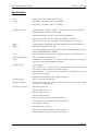
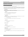
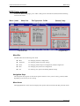
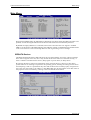
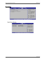
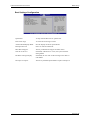
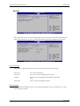
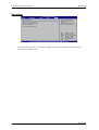
Vario Elite
Small Form-Factor PC
User Manual
Document Reference
Vario Elite Manual
Document Issue Level
1.0
Vario Elite Small Form Factor PC
Contents
Table of Contents
INTRODUCTION................................................................................................................................................... 4
COPYRIGHT......................................................................................................................................................
LIMITATIONS OF LIABILITY...................................................................................................................................
TRADEMARKS...................................................................................................................................................
REGULATORY STATEMENTS..................................................................................................................................
SAFETY WARNING FOR NORTH AMERICA...............................................................................................................
4
4
4
5
5
USER GUIDE.......................................................................................................................................................... 6
MANUAL ORGANISATION.....................................................................................................................................
6
OVERVIEW.......................................................................................................................................................
7
SPECIFICATION..................................................................................................................................................
8
PRECAUTIONS..................................................................................................................................................
10
General Precautions....................................................................................................................................... 10
PS/2 Devices................................................................................................................................................... 10
Electro-Static Discharges...............................................................................................................................10
On-Board Battery........................................................................................................................................... 10
BIOS & CMOS Memory................................................................................................................................. 11
Electromagnetic Compatibility...................................................................................................................... 11
QUICK START GUIDE.......................................................................................................................................12
SOFTWARE CONFIGURATION...................................................................................................................... 13
INSTALLING OPERATING SYSTEMS ........................................................................................................................
13
Microsoft XP................................................................................................................................................... 13
INSTALLATION................................................................................................................................................. 14
EXTERNAL CONNECTIONS..................................................................................................................................
14
PS/2 Mouse Port............................................................................................................................................................ 15
PS/2 Keyboard Port........................................................................................................................................................15
Standard VGA Port........................................................................................................................................................ 15
DVI-D Port..................................................................................................................................................................... 15
Parallel Port....................................................................................................................................................................15
USB Ports.......................................................................................................................................................................15
Ethernet Port.................................................................................................................................................................. 15
Audio – Microphone In.................................................................................................................................................. 15
Audio – Line In (Stereo)................................................................................................................................................ 15
Audio – Line Out (Stereo)............................................................................................................................................. 15
Serial Port (EIA-232)..................................................................................................................................................... 15
INTERNAL CONNECTIONS...................................................................................................................................
16
JUMPERS ........................................................................................................................................................
17
CMOS Clear....................................................................................................................................................17
Set Wake-up on Keyboard/Mouse Feature.....................................................................................................17
UPGRADING THE SYSTEM HARDWARE....................................................................................................18
WARNING......................................................................................................................................................
UPGRADE OPTIONS..........................................................................................................................................
ADDING MEMORY...........................................................................................................................................
UPGRADING/CHANGING THE CPU.......................................................................................................................
CHANGING A CHASSIS FAN ...............................................................................................................................
REPLACING THE OPTICAL DRIVE.........................................................................................................................
REPLACING THE HDD......................................................................................................................................
REPLACING THE ON/OFF SWITCH ASSEMBLY..........................................................................................................
REPLACING THE SERIAL RS232 CONNECTOR........................................................................................................
18
18
19
20
21
24
24
25
25
Page 2 of 48
History
VARIO ELITE Small Form Factor PC
REPLACING THE TV-OUT MODULE............................................................................................................................25
REMOVING THE G37 I/O BRACKET....................................................................................................................
26
REPLACING\FITTING AN OPTIONAL PCI EXPANSION CARD.......................................................................................... 27
REPLACING\FITTING AN OPTIONAL PCI EXPRESS X 16 EXPANSION CARD..................................................................... 27
REMOVING THE PSU.......................................................................................................................................
28
BIOS SETUP......................................................................................................................................................... 29
UPDATING YOUR BIOS...................................................................................................................................
29
From Bootable Floppy Disk........................................................................................................................... 29
Save Current BIOS File.................................................................................................................................................29
Updating BIOS...............................................................................................................................................................30
Using EZ Flash Utility................................................................................................................................... 31
BIOS SETUP PROGRAM....................................................................................................................................
32
Menu Bar........................................................................................................................................................ 32
Navigation Keys............................................................................................................................................. 32
Menu Items..................................................................................................................................................... 32
Sub-Menu Items.............................................................................................................................................. 33
Configuration Fields...................................................................................................................................... 33
General Help.................................................................................................................................................. 33
MAIN MENU..................................................................................................................................................
34
IDE/SATA Devices......................................................................................................................................... 34
IDE Configuration .........................................................................................................................................35
System Information.........................................................................................................................................35
ADVANCED MENU..........................................................................................................................................
36
AMD Cool 'n' Quiet Configuration................................................................................................................36
Jumper Free Configuration............................................................................................................................36
CPU Configuration........................................................................................................................................ 37
Chipset............................................................................................................................................................ 37
Northbridge Configuration............................................................................................................................................ 38
Southbridge/MCP51 Configuration...............................................................................................................................38
Hyper Transport Configuration..................................................................................................................................... 38
Onboard Devices Configuration.................................................................................................................... 39
PCI PnP.......................................................................................................................................................... 39
USB Configuration......................................................................................................................................... 40
POWER MENU................................................................................................................................................
41
APM Configuration........................................................................................................................................ 41
Hardware Monitor..........................................................................................................................................42
BOOT MENU...................................................................................................................................................
43
Boot Device Priority.......................................................................................................................................43
Boot Settings Configuration...........................................................................................................................44
Security........................................................................................................................................................... 45
User Access Level..........................................................................................................................................................45
Password Check.............................................................................................................................................................45
EXIT MENU....................................................................................................................................................
46
MAINTENANCE.................................................................................................................................................. 47
Replacing the Processor Battery....................................................................................................................47
Fuses............................................................................................................................................................... 47
AMENDMENT HISTORY..................................................................................................................................48
Page 3 of 48
VARIO ELITE Small Form Factor PC
Introduction
INTRODUCTION
Copyright
All rights reserved. No part of this publication may be reproduced, stored in any retrieval system, or
transmitted, in any form or by any means, electronic, mechanical, photocopied, recorded or otherwise,
without the prior permission, in writing, from the publisher. For permission in the UK please contact Blue
Chip Technology.
Information offered in this manual is believed to be correct at the time of printing. Blue Chip Technology
accepts no responsibility for any inaccuracies. The information contained herein is subject to change
without notice. There are no express or implied licences granted herein to any intellectual property rights of
Blue Chip Technology Ltd.
Limitations of Liability
In no event shall Blue Chip Technology be held liable for any loss, expenses or damages of any kind
whatsoever, whether direct, indirect, incidental or consequential, arising from the design or use of this
product or the support materials supplied with this product. If this product proves to be defective, Blue Chip
Technology is only obliged to replace or refund the purchase price at Blue Chip Technology's discretion
according to their Terms and Conditions of Sale.
Trademarks
All trademarks and registered names acknowledged.
IBM, PC, AT and PS/2 are trademarks of International Business Machines Corporation (IBM).
AMD is a registered trademark of Advanced Micro Devices Inc.
All Athlon processors are registered trademarks of Advanced Micro Devices Inc.
GeForce and nForce are registered trademarks of the NVIDIA Corporation
SoundMAX is a registered trademark of Advanced Micro Devices Inc.
AMI is a registered trademark of American Megatrends Inc.
MSDOS and WINDOWS are registered trademarks of the Microsoft Corporation.
Page 4 of 48
VARIO ELITE Small Form Factor PC
Introduction
Regulatory Statements
CE
This product meets the essential protection requirements of the European EMC Directive (89/336/EEC)
and its amending Directives, and the Low Voltage Directive 73/23/EEC, and is eligible to bear the CE
mark.
Warning
This is a Class A product. In a domestic environment this product may cause
radio interference in which case the user may be required to take adequate
measures.
FCC
NOTE:
This equipment has been tested and found to comply with the limits for a Class A digital device, pursuant
to Part 15 of the FCC Rules. These limits are designed to provide reasonable protection against harmful
interference when the equipment is operated in a commercial environment. This equipment generates,
uses, and can radiate radio frequency energy and if not installed and used in accordance with the
instruction manual, may cause harmful interference to radio communications. Operation of this equipment
in a residential area is likely to cause harmful interference in which case the user will be required to correct
the interference at his own expense.
WARNING:
Changes or modifications not expressly approved by the manufacturer could void the user's authority to
operate the equipment.
Safety Warning for North America
If the power lead (cord) is not supplied with the computer, select a power lead according to your local electrical
regulations. In the USA use a 'UL listed' lead. In Canada use a CSA approved or 'cUL listed' lead.
Si le cordon secteur n'est pas livré avec l'ordinateur, utiliser un cordon secteur en accord avec votre code
electrique nationale. En l'Etat Unis utiliser un cordon secteur 'UL listed'. En Canada utiliser un cordon secteur
certifié CSA, ou 'cUL listed'.
Page 5 of 48
VARIO ELITE Small Form Factor PC
User Guide - Organisation
USER GUIDE
Manual Organisation
This manual describes in detail the VARIO ELITE range of Small Form-Factor PCs.
We have tried to include as much information as possible but we have not duplicated information that is
provided in the standard IBM Technical References, unless it proved to be necessary to aid in the
understanding of the product.
The manual is sectioned as follows:
Introduction;
Overview, listing the unit's features and specification;
Installation;
Layout, showing where the various connectors are located, and their pin-out details;
How to upgrade the system;
BIOS Setup;
Maintenance details.
We strongly recommend that you study this manual carefully before attempting to interface with the VARIO
ELITE or change the standard configurations. Whilst all the necessary information is available in this manual
we would recommend that unless you are confident, you contact your supplier for guidance. IT IS
PARTICULARLY IMPORTANT THAT YOU READ THE SECTION 'PRECAUTIONS' BEFORE
HANDLING ANY COMPONENTS INSIDE THE UNIT.
If you have any suggestions or find any errors concerning this manual and want to inform us of these, please
contact our Technical Services department with the relevant details.
Page 6 of 48
VARIO ELITE Small Form Factor PC
User Guide - Overview
Overview
The VARIO ELITE is a powerful slim-line AMD Socket 939 based Personal Computer (PC) specifically
designed to drive large plasma and other large displays panels. The unit is self-contained requiring as a
minimum, only a power connection and a display. The applications are not limited to display applications: it
may be used as a general purpose PC.
The basic unit comprises a highly integrated computer board employing NVIDIA® GeForceTM 6150 GPU
Northbridge and NVIDIA® nForceTM 430 MCP Southbridge chipsets which supports AMD Athlon TM 64FX /
Athlon TM 64 X2 / Athlon TM 64 processors with 2000/1600 MT/s front side bus (FSB). Memory options allow up
to 4GB of ultra fast PC2700/PC3200 unbufferred ECC/ non-ECC DDR SDRAM. Storage is provided by a
single 3½-inch Serial ATA II 3Gb/s hard disk drive.
The on-board NVIDIA® GeForceTM 6150 GPU supports Microsoft® DirectX 9.0 Shader Model 3.0, dual VGA
out (RGB and DVI-D), NVIDIA® PureVideo Technology with unprecedented integrated video quality and TVout as standard.
Removable media options include a slim-line CD-ROM, CD-RW or DVD-ROM IDE drive.
The unit is housed in a strong sheet-steel enclosure providing both mechanical and EMC protection. Fans
draw cooling air into the unit and direct it through the chassis to ensure a wide operating temperature range.
The unit may be mounted on the plasma display, or separately to suit the particular installation. Mounting kits
are available for specific plasma displays, wall or desktop, as well as 19” Rack.
Most connectors are on the front face of the chassis. There are connectors for a PS/2 mouse and keyboard, a
standard analogue VGA display, a standard Digital Display, a serial port, a parallel port, four USB (2.0) ports,
an Ethernet (10/100/1Gb) LAN port, a 1394a Firewire port and three audio connectors . The on-board audio
system may be configured from simple stereo to a full 5.1 surround system.
Additional I/O capability can be provided by one of the following
l
an optional PCI Express x 16 expansion card
l
a short 32-bit PCI (2.2) expansion card
l
an additional 1394 port
l
an additional 2 x USB 2.0 ports
l
a S/PDIF out interface
The above order is configurable at time of order only.
The AC power inlet connector is at the rear of the chassis. The power supply unit is auto-ranging to cover most
markets.
External indicators and controls on the front face of the chassis are limited to a hard drive activity LED, a
power on LED and a power/standby push-button switch. The LAN connector also includes LEDs indicating a
connection and data rate.
Page 7 of 48
VARIO ELITE Small Form Factor PC
User Guide - Specification
Specification
CPU:
AMD Athlon TM 64; AMD AthlonTM 64 X2
Chipset:
Northbridge: NVIDIA® GeForceTM 6150 GPU
Southbridge: NVIDIA® nForceTM 430 MCP
Graphics Controller:
Integrated in the NVIDIA® GeForceTM 6150 Graphics Processing Unit (GPU)
Dual VGA Output: DVI-D/TV-OUT, RGB
Maximum Resolution of 1920 x 1440 pixels for RGB dispaly
848x480, 1280x720, 1280x768, 1368x768, 1024x512, 1024x1024
Picture rotation 0, 90, 180, 270 degrees without degradation, as standard.
BIOS:
4 Mb Flash ROM, AMI BIOS, PnP, DMI, WfM2.0, ACPI 2.0a, SM BIOS 2.3
Memory:
Dual Channel memory architecture
4 x 184-pin DIMM sockets supporting up to 4Gb of unbufferred ECC/non-ECC
400/333 MHz DDR memory modules
LAN:
Integrated in the NVIDIA® nForceTM 430 MCP, supporting 10/100/1Gb rates
System Management:
CPU and system voltage detection.
Audio:
SoundMAX® ADI AD1986A 5.1-channel CODEC supporting Jack Sensing
technology, with optional S/PDIF out interface
Expansion Slot:
one from either
One 32-bit PCI v2.2 slot riser card for short PCI expansion card. Maximum
card length 175 mm to rear face of connector bracket.
One PCI-Express x 16 slot riser card. Maximum card length 175mm to rear
face of connector bracket
Additional I/O from either 1394a, USB2 or S/PDIF
Primary Storage:
One 3½” SATA II hard disk drive.
Secondary Storage:
Single slim-line drive bay supports optional IDE slim-line CD-ROM, CD-RW
or slim-line DVD-ROM drive.
External I/O Interface:
PS/2 Mouse connector.
PS/2 Keyboard connector.
Standard VGA connector
Digital DVI-D connector.
One 9-way Serial connectors (16550 compatible).
25-way Parallel port connector (SPP, EPP, and ECP).
Four USB 2.0 connectors.
One IEEE 1394a connector
RJ-45 10/100/1Gb Base-T Ethernet LAN connector.
Audio Microphone In, Line In and Line Out sockets.
Page 8 of 48
VARIO ELITE Small Form Factor PC
User Guide - Specification
Indicators:
Power On LED, Hard drive activity LED
Control:
Power standby pushbutton switch,
Watchdog:
Programmable timer, 2.4 to 37 seconds.
System Management:
CPU temperature monitoring, system temperature monitoring, and voltage
monitoring of Vcore, +3.3V, +5V, +12V, -12V are all available to the
application for monitoring and reporting.
Power Requirements:
Auto-ranging 115 - 230V / 4 – 2A / 60 - 50Hz, with IEC320 power inlet.
Environmental Conditions:
Operating temperature range +5 °C to +40 °C in free air.
Storage temperature range -20 °C to +70 °C
Relative Humidity 10-85% non-condensing.
Shock and vibration compatible with light industrial usage.
Construction:
Painted zinc-plated sheet steel, welded and riveted construction.
Dimensions:
425 x 337 x 44.5 mm, excluding the mounting brackets.
Note that an additional 130 mm will be required in front of the CD/DVD for the
tray to eject, and at least 60 mm to allow easy access to the cable connectors.
Air vents must not be obstructed. A minimum gap of 25 mm between side
vents and any adjacent items is recommended. A minimum gap of 45mm above
the top of the chassis is also required.
Page 9 of 48
VARIO ELITE Small Form Factor PC
User Guide - Precautions
Precautions
General Precautions
Before attempting any modification to, or internal adjustment of the VARIO ELITE PC, please read the
following sections carefully.
Certain precautions are necessary when handling circuit boards and
equipment containing them. Failure to observe the precautions could result in being unable to operate the
equipment, damage to the product, or in extreme cases, personal injury. It is imperative that precautions
are taken at all stages to avoid electro-static discharges, which will damage boards. Boards fitted with an
on-board lithium battery must be handled carefully to avoid maltreatment of the battery that could create a
hazard.
Under no circumstances should the power supply unit be disassembled. Dangerous voltages exist within
the power supply enclosure. Note that the IEC-320 AC supply connector is the AC supply disconnect
device.
PS/2 Devices
It is important that PS/2 devices (mouse and keyboard) are not connected or disconnected with the unit
powered on. Damage or data corruption may occur if this precaution is not observed.
Electro-Static Discharges
If you are going to open up the unit, it is important to realise that the devices on the cards within this unit
can be damaged by static electricity. Bear in mind that the damage caused by static electricity may vary
from total destruction to partial damage, which may not be immediately obvious. This could have an effect
on the product's reliability and warranty. Before opening the chassis, ensure that you take necessary static
precautions. Ideally you should work at an anti-static bench and wear an approved wrist strap or if that is
not possible, touch a suitable ground to discharge any static build up before touching the electronics. This
should be repeated if the handling continues for any length of time.
If it is necessary to remove a board or electronic assembly, place it into an anti-static bag. This will prevent
any static electricity build up damaging the board. Metallised bags are preferred. Do not use black antistatic bags for any item containing a battery because these tend to be conductive and will discharge the
battery.
On-Board Battery
The processor board is fitted with a Lithium battery. Great care should be taken with this type of battery.
If the battery is mistreated in any way there is a very real possibility of fire, explosion, and personal harm.
Under NO circumstances should it be short-circuited, exposed to temperatures in excess of 100C or burnt,
immersed in water, recharged or disassembled.
Expired batteries remain hazardous and must be disposed of in a safe manner, according to local
regulations.
Le panneau de processeur est équipé d’une batterie de lithium. Le grand soin devrait être pris avec ce type
de batterie. Si la batterie est mistreated il y a de dans de toute façon un possibility très vrai du feu,
d’expolosion et de mal personnel. Dans au cunes circonstances il est sous peu circuité, exposé aux
températures au dessus de 100 degrés de centrigrade ou brûlé, immergé dans l’eau, rechargée ou
dissassambled.
Les batteries expirées restent dazaedous et doivent être reejetées d’une façon sûre, selon des règlements
locaux.
Page 10 of 48
VARIO ELITE Small Form Factor PC
User Guide - Precautions
BIOS & CMOS Memory
Please be aware that with personal computer products, it is possible to create configurations within the
CMOS memory that make booting impossible. If this should happen, clear the CMOS settings; (see the
description of the Jumper Settings on Page 17 for details).
Electromagnetic Compatibility
This product meets the requirements of the European EMC Directive (89/336/EEC) and its amending
Directives, and the Low Voltage Directive 73/23/EEC. It is eligible to bear the CE mark. However,
because the unit can be installed in a wide variety of situations, certain conditions have to be applied to
ensure that the compatibility is maintained. Subject to those conditions, it meets the requirements for an
ITE Class A product.
•
The VARIO ELITE PC must be supplied with a clean AC supply, and the chassis should be
connected to a sound earth (ground). As a minimum the power cord must be connected to an
earthed (grounded) supply or outlet. Additionally, an earthing stud is provided on the chassis. It
is good practice to connect this independently to a suitable earth in fixed installations.
•
When installing additional items, any recommendations made by the component
manufacturer/supplier must be complied with regarding earthing and the installation.
•
The metal back plate of any expansion card must be securely screwed to the chassis of the
computer to ensure good metal-to-metal (i.e. earth) contact.
•
All connector bodies must be securely connected to the enclosure.
•
Most EMC problems are attributable to the external cabling. It is imperative that any external
cabling to the unit is totally screened, and that the screen of the cable connects to the metal end
bracket of the board or the enclosure and hence to earth. It is recommended that round, screened
cables with a braided wire screen be used in preference to those with a foil screen and drain wire.
Use metal connector shells that connect around the full circumference of the cable screen: they are
far superior to those that earth the screen by a simple “pig-tail” connection. This method attempts
to extend the enclosure around the connecting cables, thereby trying to surround the whole of the
internal equipment and external cabling.
•
The keyboard and mouse will play an important part in the compatibility of the processor card
since they are ports into the board. Similarly, they will affect the compatibility of the complete
system. Fully compatible peripherals must be used otherwise the complete system could be
degraded. They may radiate or behave as if keys/buttons are pressed when subject to interference.
Under these circumstances it may be beneficial to add a ferrite clamp on the leads as close as
possible to the connector.
•
USB cables must be high quality screened types suitable for USB 2.0, and peripherals must be
approved to equivalent EMC standards.
•
Where possible ensure that the screens of any external cables are also bonded to a good RF earth
at the remote end of the cable.
Failure to observe these recommendations may invalidate the EMC compliance.
Page 11 of 48
VARIO ELITE Small Form Factor PC
Quick Start Guide
QUICK START GUIDE
First ensure that you are familiar with the contents of the section "Precautions". It contains important
information to avoid damage to the unit.
The unit may be used free-standing, but it is recommended that it be securely mounted to avoid accidental
damage. The actual mounting details will vary depending upon the application.
There are four M3 tapped holes on each end of the chassis for mounting brackets, etc. Do not use screws
longer than those supplied to mount the unit, otherwise internal damage may result. If alternative screws are
used, please ensure that they do not enter the chassis by more than 5mm, otherwise internal damage may
result.
Particular mounting arrangements exist for NEC plasma displays. Others will be available. Mounting details
can be found on the Blue Chip Support CD which is supplied with your unit, or from
www.bluechiptechnology.co.uk if what you need is not in these places then contact
[email protected] with details of the particular mounting arrangement you require
If the unit is to be used free-standing fit the adhesive synthetic rubber feet to the base. These will prevent the
unit slipping on a smooth surface.
Connect the display to the VGA connector, and connect any other signals, e.g. LAN. Connect a PS/2 mouse
and keyboard to the unit.
Connect the power lead to a suitable AC power source. It is recommended that the supply be fused at 5A.
Press the 'Power On' button and check that the unit boots up.
If your system was not supplied with an operating system pre-installed, load an operating system and drivers.
The section "Software Configuration" contains details for the common operating systems.
Set up the required video display parameters.
The system is now ready to have the applications software loaded.
If the mouse and keyboard are to be removed for normal operation, shut down the computer and switch off
the power before removing them.
Page 12 of 48
VARIO ELITE Small Form Factor PC
Software Configuration
SOFTWARE CONFIGURATION
Installing Operating Systems
Your VARIO ELITE Small Form-Factor PC may have been supplied complete with a software operating
system, in which case the appropriate drivers will have been loaded.
If it has been supplied without an operating system, one must be loaded following the instructions supplied
with the software. It is then necessary to add driver programs for the specific hardware of the motherboard
and any additional expansion cards. The manner in which the drivers are loaded will vary depending upon
the actual operating system used. Details follow for Microsoft XP.
Microsoft XP
To install the drivers for Windows XP, you can either follow the guided install from the Blue Chip
Technology Support CD or manually install in order as follows.
INFUpdate
This update must be applied before installing any other drivers.
To install, go to the following directory on the Support CD
\Drivers\INFUpdate\
Run amdcpu.exe
Chipset Drivers
The integrated chipset driver provides support for IDE, SATA, LAN and SM Bus, and can be found in
either 32Bit or 64 Bit format. For 32 bit operating system support
\Drivers\chipset\32bit
From this directory, run the Setup.exe program and follow the on-screen instructions.
Video Drivers
The Video drivers are located on the Support CD at
\Drivers\Video\
Run 84.21_whql.exe
and follow prompts
Audio Drivers
The Audio Drivers are located on the CD at
\Drivers\Audio\
Run Setup.exe and follow instructions to install the Driver.
Watchdog Utility
The USB Watchdog is an additional item, and may be fitted on some units. The drivers for this can be
found on the CD can be found at
\Drivers\Watchdog\
Prompt Device Manager to the INF file in this directory. Refer to Watchdog Documentation for further
details.
Page 13 of 48
VARIO ELITE Small Form Factor PC
Installation
INSTALLATION
External Connections
The external connectors on the front face are shown on the following diagram: -
Picture 1: External Connections
External Connectors
1
PS/2 Mouse (Green)
2
Parallel Port
3
IEEE 1394a
4
RJ-45 LAN
5
Line In ( Light Blue )
6
Line Out ( Lime )
7
Microphone ( Pink )
8
USB Ports 3 and 4
9
USB Ports 1 and 2
10
VGAOut
11
DVI out
12
PS/2 Keyboard (Purple)
13
RS232
14
S-Video
14
TV-OUT
Picture 2: External Connections 2
Page 14 of 48
VARIO ELITE Small Form Factor PC
Installation
PS/2 Mouse Port
PS/2 6-pin mini-DIN socket.
Mating Connector: PS/2 mouse connector.
PS/2 Keyboard Port
PS/2 6-pin mini-DIN socket.
Mating Connector: PS/2 keyboard connector.
Standard VGA Port
High-density 15-pin D-type socket.
Mating Connector: High-density 15-pin D-type plug.
DVI-D Port
DVI-D socket.
Mating Connector: DVI-D type plug.
Parallel Port
25-way D-type socket.
Mating Connector: 25-pin D-type plug.
USB Ports
Series A USB socket.
Mating Connector: Series A USB connector
Ethernet Port
RJ-45 8-pin shielded socket.
Mating Connector: RJ-45 8-pin plug.
Audio – Microphone In
3.5mm Jack-socket.
Mating Connector: 3.5mm Jack-plug
The Tip is microphone input suitable for dynamic microphone of not greater than 600 Ohms impedance.
Audio – Line In (Stereo)
3.5mm Jack-socket.
Mating Connector: 3.5mm Jack-plug
The Tip is right channel.
Audio – Line Out (Stereo)
3.5mm Jack-socket.
Mating Connector: 3.5mm Jack-plug
The Tip is right channel.
Serial Port (EIA-232)
9-way D-type plug.
Mating Connector: 9-pin D-type socket.
Page 15 of 48
VARIO ELITE Small Form Factor PC
Installation
Internal Connections
There are connectors on the main processor board for the CPU, memory, power and various additional
peripherals. For the location of these items please see the photograph below. Your board may vary slightly from
that shown.
Picture 3: Motherboard layout
Page 16 of 48
VARIO ELITE Small Form Factor PC
Installation
Jumpers
The processor board used in the VARIO ELITE PC is largely free of selection jumpers. Most settings are
controlled from the BIOS, and stored in the CMOS memory.
Only the following jumpers are significant.
CMOS Clear
To clear the CMOS memory, first switch off the PC power, then locate the 3-pin header labelled
‘CLRTC’ on the processor board which is beside the battery connector. Remove the link shorting pins 1
and 2, and place it on pins 2 and 3 for about 5 - 10 seconds. Remove the link and replace it in its
original position. The CMOS has now been cleared and the BIOS will be reset to the default settings.
Having no link fitted is an invalid option.
Picture 4: Clearing CMOS
Set Wake-up on Keyboard/Mouse Feature
When enabled, this feature allows the user to wake the computer when a key is pressed. Note as well as
the jumper, this feature also needs to be enabled in BIOS. Refer to BIOS Setup Section for details
Picture 5: Keyboard Power
Page 17 of 48
VARIO ELITE Small Form Factor PC
Upgrading the System Hardware
UPGRADING THE SYSTEM HARDWARE
Warning
Before attempting any upgrade to the VARIO ELITE computer, please read the section "Precautions".
For your personal safety it is important that you ensure that the unit is switched off, and the AC supply is
disconnected. Remember that the unit incorporates an ATX-type of power supply unit. Switching the power
off using the front panel switch does not isolate the AC supply, and under these conditions the +5V DC standby
power is still connected to the motherboard.
For the safety of the equipment, it is important that you observe electrostatic discharge precautions. Do not
remove items from anti-static bags until necessary.
When making any internal changes to the computer, it is imperative that the internal cables follow the original
routes and additional cables are installed as described. Failure to observe this requirement could restrict the
airflow through the unit and cause overheating problems.
Upgrade Options
The user may upgrade the unit by adding more memory or a faster CPU to the unit. Before upgrading, please
check with Blue Chip Technical support by emailing [email protected] to find out if your
proposed upgrade is supported.
The addition of removable-media drives (CD or DVD) is normally a build option, because it requires the
appropriate upgrade kit, and requires a measure of disassembly.
With the Vario Elite, there is also the possibility of supporting a single expansion card option. This support is
configurable at time of order due to the requirement for a specific riser solution, and the Unit can be configured
to support ONE of the following
l
an optional PCI Express x 16 expansion card
l
a short 32-bit PCI (2.2) expansion card
l
an additional 1394 port
l
an additional 2 x USB 2.0 ports
l
a S/PDIF out interface
Unauthorised upgrades may invalidate the warranty.
Page 18 Of 48
VARIO ELITE Small Form Factor PC
Upgrading the System Hardware
Adding Memory
There are 4 184-pin DIMM sockets for 128, 256, 512MB or 1GB unbuffered ECC/non-ECC of
PC2700 or PC3200 compliant DDR SDRAM. Provides up to 4GB of system memory.
Picture 6: DIMM Sockets
Possible memory configurations are shown below
Sockets
Mode
Single Channel
Dual Channel
DIMM_A2
DIMM_A1
DIMM_B2
DIMM_B1
(blue)
(blue)
(black)
(black)
-
Populated
-
-
Populated
Populated
-
-
Populated
Populated
Populated
Populated
Table 1: Possible memory Configurations
Note that when using multiple DIMMs then the modules must be matched pairs
Page 19 Of 48
VARIO ELITE Small Form Factor PC
Upgrading the System Hardware
Picture 7: Inserting/removing DIMM
The DIMM module is removed by pulling back the retaining clip as shown in Picture 7. When
inserting a DIMM align the notch correctly before pushing home. If pushed correctly, the retaining
clip will lock the DIMM in place
Upgrading/Changing the CPU
Insert the CPU in the orientation as shown in Picture 8. Unlock the socket by pressing the lever
sideways and lifting up to a 90° – 100° angle. Carefully insert the processor, and then lower the lever,
ensuring that it is locked closed
Picture 8: CPU Orientation
Note: if the lever is not fully upright, then the pins on the CPU may get damaged during insertion
Page 20 Of 48
VARIO ELITE Small Form Factor PC
Upgrading the System Hardware
Once the CPU is installed, attach the heatsink. Place the heatsink onto the processor and line up the
holes with the mounting plate before inserting the screws.
Picture 9: Assembling the CPU heatsink
Changing a Chassis Fan
If a chassis fan fails, then it should only be replaced with a fan of similar dimensions and
specifications. Failure to do so may result in the system overheating and cause other components such
as CPU and PSU to fail
Picture 10: Fan Connector Locations
Page 21 Of 48
VARIO ELITE Small Form Factor PC
Upgrading the System Hardware
Picture 11a CPU Fan assembly
Picture 11b Removing fans from mounting plate
The 2 CPU fans are attached to a mounting plate as shown in Picture 11a. To remove the assembly,
there are four screws indicated which need to be removed beforehand. The assembly is then removed
vertically from the chassis.
The fans themselves are attached to the mounting plate by two screws each. The two CPU fans are
wired together, and both should be replaced at the same time if one fails. The fans are connected to a
connector attached to the System Fan, which is plugged into the CPU_Fan Connector shown in Picture
10.
Page 22 Of 48
VARIO ELITE Small Form Factor PC
Upgrading the System Hardware
Picture 12 System Fan
The system fan is located between the PSU and the HDD. The fan is held in place by two screws as
shown in Picture 12. The fan is plugged into the CPU_Fan Connector shown in Picture 10
If difficulty is found trying to access the top screw, due to the PSU cable loom, then the PSU can be
removed from the chassis beforehand.
Picture 13 Expansion fan
The optional Expansion fan is only fitted when either a PCI-Express or PCI card is also fitted. The fan
is held in place by two screws shown in Picture 13. The fan is connected to the CHA_FAN connector
shown in picture 10.
Page 23 Of 48
VARIO ELITE Small Form Factor PC
Upgrading the System Hardware
Replacing the Optical Drive
The Optical drive is a Factory fitted Option. It relies on two mounting brackets attached to the HDD. These
brackets are not fitted as standard. The Optical drive is held in place by three screws shown below in Picture 14
Picture 14 Optical Drive Mounting
Replacing the HDD
The HDD is fitted directly to the base of the chassis by means of 4 screws shown in Picture 15
Picture 15 HDD mounting
Page 24 Of 48
VARIO ELITE Small Form Factor PC
Upgrading the System Hardware
Replacing the On/Off switch assembly
The On/Off Switch assembly is held in place by a single screw shown in Picture 16.
Picture 16 Front Panel On/Off Switch and RS232 Connectors
The switch is part of a cable loom which also contains two LEDs which plug into the front of the chassis below
the switch. The Green LED is fitted directly below the power switch., and the Orange Drive Activity LED is
fitted between the Green LED and the Audio Output connector.
Replacing the Serial RS232 Connector
The RS232 connector is shown in Picture 16 on the previous page. This connector is held in place by two small
nuts. These can be removed using a 5AF hexagonal driver.
Replacing the TV-Out Module
The TV-OUT module is fitted underneath where an expansion card can be fitted. To remove the TV-Out
Module, it is necessary to remove any expansion card fitted, or the G37 I/O bracket if no expansion card is
fitted. A slim bodied screwdriver is required as access is through holes in the metalwork as shown in Picture 17
Picture 17 TV Out Module
The module is held in place by two screws shown
Page 25 Of 48
VARIO ELITE Small Form Factor PC
Upgrading the System Hardware
Removing the G37 I/O Bracket
All expansion cards are fitted with an I/O bracket. If no expansion card is fitted then a G37 blank I/O panel is
fitted.
Picture 18a G37 Expansion bracket
To remove the bracket, the two screws shown in Picture 18a need to be removed first. The G37 assembly is
then moved to the right and pushed backwards to release it from its guide. The G37 bracket can then be
removed from the locating bracket as shown is Picture 18b below
Picture 18b G37 bracket and locating bracket.
Page 26 Of 48
VARIO ELITE Small Form Factor PC
Upgrading the System Hardware
Replacing\Fitting an optional PCI expansion card
PCI Expansion capability is a factory fit option. The PCI card and cable is attached to a bracket which is not
fitted as standard.
Picture 19 PCI Card mounting
To first remove the expansion card, remove the two screws and brackets as shown in Picture 19. With these
removed, pull the cable and connector away from the expansion card. The expansion card can now be removed
by following the same procedure outlined in the previous section Removing the G37 I/O bracket.
Replacing\Fitting an optional PCI Express x 16 expansion card
PCI-Express Expansion capability is a factory fit option. The PCI-Express card and cable is attached to a
bracket which is not fitted as standard.
Picture 20PCI-Express Card mounting
To first remove the expansion card, remove the two screws and brackets as shown in Picture 19. With these
removed, pull the cable and connector away from the expansion card. The expansion card can now be removed
by following the same procedure outlined in the previous section Removing the G37 I/O bracket.
Page 27 Of 48
VARIO ELITE Small Form Factor PC
Upgrading the System Hardware
Removing the PSU
To remove the PSU it is first necessary to remove the PSU Bracket shown below in Picture 21.
Picture 21PSU Bracket
The bracket is held in place by 6 screws shown above. Once removed. The bracket is removed verically from
the chassis
Picture 22PSUEnd mounting
Lastly, the PSU is now only held in place by two screws attached to a small bracket at the rear of the PSU.
Remove these two screws and the PSU can be removed by tilting in the direction of the arrow as shown in
Picture 22
Page 28 Of 48
VARIO ELITE Small Form Factor PC
BIOS Setup
BIOS SETUP
To enter the BIOS Setup pages, press <DEL> during Power-On-Self-Test (POST).
If you have made any changes to the BIOS Setup which you think may be causing you problems, then when you enter
the BIOS Setup pages select LOAD DEFAULT SETTINGS item under the EXIT menu to load the default BIOS
settings.
If your BIOS needs to be updated for any reason, please check the Blue Chip Technology Website
www.bluechiptechnology.co.uk to see if there is a later BIOS, or alternatively contact
[email protected]
Updating Your BIOS
There are several methods available to update your BIOS.
From Bootable Floppy Disk
Copy the AFUDOS.exe program from the Support CD to the floppy disk as well as the latest BIOS file.
Save Current BIOS File
In case of problems with the new BIOS it is advisable to save the old one before installing the new one.
To do this, boot the system using the Floppy disk and at a command prompt enter
afudos /o{filename}
where file name is the name of the saved file, for example
This will copy the BIOS to the floppy drive and when complete you will see the following
Page 29 of 48
VARIO ELITE Small Form Factor PC
BIOS Setup
Updating BIOS
Once the old BIOS has been saved, enter the following
afudos /i{new filename}
where {new filename}is the name of the new BIOS for example
When the BIOS has installed the following will be shown
Page 30 of 48
BIOS Setup
VARIO ELITE Small Form Factor PC
Using EZ Flash Utility
The BIOS chip has a feature which allows the reprogramming of the BIOS during POST. To do this
the new BIOS file should be added to a floppy disk.
During POST, press <Alt><F2> and the following is displayed
The utility will then search the floppy for a ********.rom file, so ensure that only one such file exists
on the floppy drive. When complete the screen will look like the following
and the system will automatically reboot.
IMPORTANT: DO NOT POWER OFF THE SYSTEM UNIT
WHILE THE BIOS UTILITIES ARE RUNNING.
DOING SO WILL CORRUPT THE BIOS
AND YOU MAY REQUIRE A NEW MOTHERBAORD
Page 31 of 48
BIOS Setup
VARIO ELITE Small Form Factor PC
BIOS Setup program
To enter the BIOS Setup pages, press <DEL> during Power-On-Self-Test (POST) and the following
screen will be shown
Sub-menu items
Navigation keys
Menu Bar
The Menu Bar has the following main items
●
Main
For changing the basic configuration
●
Advanced
For changing advanced system settings
●
Power
For changing advanced power management (APM) configuration
●
Boot
For changing the system boot configuration
●
Exit
For selecting exit options and loading default settings
Navigation Keys
The Navigation keys appear on the bottom right of whatever screen you are viewing, and may differ
depending on the screen you are viewing
Menu Items
The highlighted item on the menu bar displays the specific items associated with that particular menu
Page 32 of 48
VARIO ELITE Small Form Factor PC
BIOS Setup
Sub-Menu Items
On each page being viewed, a solid triangle indicates that the particular item has a sub-menu. Use the
navigation keys to select the item and press <Enter> to display the sub-menu
Configuration Fields
A configuration field is show in brackets and when selected and <Enter> is pressed, a pop-up menu is
displayed. The new menu item can then be highlighted and pressing <Enter> once again will select
the new option.
Where there are a number of user selectable options, a slide bard will appear in the pop-up window.
Press the <Page Up>/<Page Down> keys to scroll up and down the list
General Help
At the top right corner of the screen, a brief description of the selected item is shown
Page 33 of 48
VARIO ELITE Small Form Factor PC
BIOS Setup
Main Menu
When entering BIOS Setup, the Main Menu is displayed. This allows the System Date and Time to be
updated, as well showing the IDE and SATA devices which have been automatically detected.
By default the Legacy Diskette A is selected, however the Vario Elite does not support a standard
FDD so, set this device to Disabled whenever the CMOS is cleared, or Default Settings loaded. Failure
to do so will result in a slow boot through POST as well as generating an error message.
IDE/SATA Devices
The BIOS automatically detects IDE and SATA devices during POST. If you have a device installed
but it does not appear in this list, then it may be that the device is either not connected correctly, or
there is a failure associated with it such as, faulty signal or power cables, or faulty device
By selecting the device itself, more information on the particular device is shown. In cases where
system items are not working as expected in the operating system, checking the settings for the device
and comparing it with its specification may show that the device has not been properly recognised. If
this is the case, then check to see if there is a later BIOS that may fix this problem. If not then some of
the properties can be set manually, referring to the User Manual for the device
Page 34 of 48
VARIO ELITE Small Form Factor PC
BIOS Setup
IDE Configuration
This menu allows you to enable and disable the SATA ports as well as the SATA Raid function. Note
that the Vario Elite only supports one Hard Drive, and as such the Raid function should be set to
Disable
System Information
This page shows the BIOS level information as well as the details of the CPU and memory detected
Page 35 of 48
BIOS Setup
VARIO ELITE Small Form Factor PC
Advanced Menu
AMD Cool 'n' Quiet Configuration
The only options for this sub-menu are to enable or disable this option
Jumper Free Configuration
This option allows the user to select the appropriate overclocking option. There are 3 choices
●
Auto
loads the optimal settings for the system
●
Standard
loads the standard settings for the system
●
Manual
allows individual to set overclocking parameters
●
CPU FSB Frequency
The FSB frequency can be adjusted from 200 to 240
Page 36 of 48
VARIO ELITE Small Form Factor PC
BIOS Setup
CPU Configuration
This screen shows the CPU information auto detected by the BIOS
Chipset
Within the Chipset menu, there are 3 sub-menus as shown above
Page 37 of 48
VARIO ELITE Small Form Factor PC
BIOS Setup
Northbridge Configuration
This menu allows the user to manually configure both memory and ECC configurations. Caution:
incorrect settings can cause the System to be unstable.
The item most likely to require configuration is the NvigpBridge/C51PV Chipset Configuration
The Primary Graphics Adapter option determines where the video output is displayed on system boot.
Southbridge/MCP51 Configuration
The Southbridge has the capability of adjusting the clocks slightly during operation so as to minimise
EMC emissions. Options allow the user to adjust or disable this. Caution: it is recommended that this
is left at the default setting
Hyper Transport Configuration
This page allows the configuration of the bus links between CPU, Northbridge and Southbridge.
Caution: it is recommended that this is left at the default setting
Page 38 of 48
VARIO ELITE Small Form Factor PC
BIOS Setup
Onboard Devices Configuration
This page allows the enabling and configuration of the following
●
Serial Port
●
Parallel Port
●
On Board Audio
●
On Board LAN
PCI PnP
This page allows the user to change the advance settings for PCI/PnP devices. For most users, the only
item that may be changed will be setting the Plug And Play O/S option to Yes or No
Page 39 of 48
VARIO ELITE Small Form Factor PC
BIOS Setup
USB Configuration
For Legacy USB Support, if set to Auto, the BIOS will detect the presence of USB devices at start-up,
and if detected will enable legacy USB support. If no devices are detected then Legacy USB support
will be disabled
Page 40 of 48
BIOS Setup
VARIO ELITE Small Form Factor PC
Power Menu
This menu allows the user to change the APM settings
APM Configuration
The APM settings can be adjusted as follows
Power Button Mode
Allows the system to go On/Off or Suspend mode
Resume On PME#
Wake from Soft-Off mode by PME
Resume On Ring
Wake from Soft-Off mode by RI
Resume On Lan
Turn on system from PCI Lan or Modem card
Resume on RTC Alarm
Wake form pre-set time in RTC
Power On By PS/2 Keyboard Turn on the system from keyboard press
Power On By PS/2Mouse
Turn on the system from Mouse activity
Restore On AC power Loss
After power loss, sets the state when power is restored
-options
Power OFF – system remains off
Power On – system automatically turns itself back on
Last state – goes back to the state it was before power loss
Page 41 of 48
VARIO ELITE Small Form Factor PC
BIOS Setup
Hardware Monitor
If your system is shutting down and you suspect a thermal issue, this page will show you the CPU core
temperature. Temperature will depend on ambient, however at around 20C, the CPU reading should
be less than 50°C
Page 42 of 48
VARIO ELITE Small Form Factor PC
BIOS Setup
Boot menu
Boot Device Priority
Page 43 of 48
BIOS Setup
VARIO ELITE Small Form Factor PC
Boot Settings Configuration
Quick Boot
To skip some POST tests for quicker boot
Full Screen Logo
To show full screen logo on boot
Add On ROM Display Mode
Sets the display mode for option ROM
Bootup Num-Lock
Power on state for NumLock
PS/2 Mouse Support
Allows you disable the support for PS/2 mouse
Wait for F1 If error
If enabled, if POST error occurs, the system will halt
during POST
Hit 'DEL' message Display
If enabled, the user will see the message to hit 'DEL' to
enter BIOS
Interrupt 19 Capture
Allows any enabled option ROM to capture interrupt 19
Page 44 of 48
BIOS Setup
VARIO ELITE Small Form Factor PC
Security
This area allows the user to set and change Supervisor and User passwords. Password should be at
least 6 letters/numbers long. If set, a further menu appears which allows different access levels
User Access Level
This enables or disables the normal user form accessing the Setup menu as follows
No Access
User cannot enter Setup
View Only
User can view but not change items in Setup
Limited
User can access and change limited fields such as Date
/Time
Full Access
User can View and Change all fields
Password Check
When Passwords enabled, this can be set to checking passwords on entry into Setup only , or also
when booting the system
Page 45 of 48
VARIO ELITE Small Form Factor PC
BIOS Setup
Exit menu
This menu allows the user to Load default settings, as well as Exiting BIOS and either saving or
discarding any changes made
Page 46 of 48
VARIO ELITE Small Form Factor PC
Maintenance
MAINTENANCE
On a regular basis the inside of the VARIO ELITE unit should be cleaned out to prevent dust build up which
could eventually clog the fans and prevent efficient operation. Generally the enclosure design and the wiring
layout will ensure that the cooling is stable. However, bear in mind that any modifications to the installation
may cause a restriction of the air vents.
After a period of several years, it may be necessary to replace the battery on the processor board, if it cannot
maintain the CMOS memory whilst the AC power is disconnected.
Replacing the Processor Battery
The processor board includes a small 3V lithium battery (type CR-2032) to retain the BIOS settings in the
CMOS memory. Before attempting to replace the battery, please read the precautions detailed in the
introductory section. Remember that even discharged batteries can present a real personnel hazard if
mistreated.
CAUTION
Danger of explosion if battery is incorrectly replaced.
Replace only with the same or equivalent type recommended by the
manufacturer.
Dispose of used batteries according to the manufacturer's instruction.
ATTENTION
Il y a danger d'explosion s'il y a remplacement incorrect de la batterie.
Remplacer uniquement avec une batterie du même type ou d'un type
recommandé par le constructeur.
Mettre au rébut les batteries usagées conformément aus instructions du
fabricant.
The battery is located on the motherboard in the bottom right hand corner as shown in Picture 3 on Page
16.
Do NOT under any circumstances try to remove the battery with metallic tools (pliers, tweezers etc.).
They will short out the battery with possible disastrous results.
Replace the battery by one of the same type, ensuring that it is fitted with the positive terminal facing the
CPU, and that the clip is fully engaged. When the battery has been replaced, the BIOS settings will revert
to their default settings. Reset them as necessary to suit your application.
Fuses
There are no user-serviceable or replaceable fuses within the unit.
Page 47 of 48
History
VARIO ELITE Small Form Factor PC
AMENDMENT HISTORY
Issue Level
1.0
Issue Date
27/06/06
Author
tmck
Amendment Details
First Releaset
Blue Chip Technology Ltd.
Chowley Oak
Tattenhall
Chester
CH3 9EX
U.K.
Telephone: +44 (0)1829 772000
Facsimile: +44 (0)1829 772001
www.bluechiptechnology.co.uk
Page 48 of 48