1
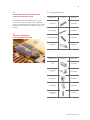
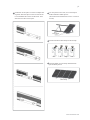
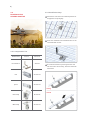
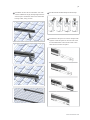
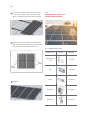
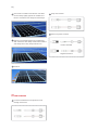
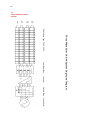
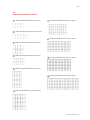
TOTAL KITS
INSTALLATION
MANUAL
1.0
|4
GENERAL INFORMATION
2.0 SAFETY PRECAUTIONS
|4
3.0 STRUCTURE AND PV MODULE INSTALLATION
|4
4.0 DC CABLE WIRING
|6
5.0
|7
DC AND AC ISOLATOR CABLE WIRING
6.0 INVERTER INSTALLATION AND WIRING
|10
7.0 ON-GRID SYSTEM SINGLE LINE DIAGRAM
|12
8.0 PV MODULE REFERENCE LAYOUT
|12
www.canadiansolar.com
4 |
1.0
GENERAL INFORMATION
trically active parts of the module, such as terminals,
can result in injury or death, whether the module
and the other electrical equipments are connected
This general manual provides important safety infor-
or disconnected.
mation relating to the installation, maintenance and
handling of CS-series solar modules. System users
GENERAL SAFETY
and professional installers should read this manual
carefully and strictly follow the instructions in the
manual.
· All installations must be performed in compliance
with all applicable regional and local codes or
other national or international electrical standards.
Failure to follow these instructions may result in
death, injury or property damage. The installation
Wear suitable protection (non-slip gloves,
of solar modules and other electrical equipments
clothes, etc.) to prevent direct contact with
requires specialized skills and should only be perfor-
30VDC or greater, and to protect your
med by licensed professionals.
hands from sharp edges during the installation.
Please retain this manual for future reference. It is
recommended to regularly check on
Remove all metallic jewelry prior to
www.canadiansolar.com
installation to reduce the chance of
for the most updated version.
accidental exposure to live circuits.
1.1
DISCLAIMER OF INSTALLATION MANUAL
· Use electrical insulated tools to reduce the risk of
electric shock.
· Cover the front of the modules in the PV array with
The information contained in this manual is sub-
an opaque material to halt production of electri-
ject to change by Canadian Solar Inc. without prior
city when installing or working with a module or
notice. Canadian Solar Inc. makes no warranty of
wiring.
any kind whatsoever, either explicitly or implicitly,
with respect to the information contained herein.
· Do not install or handle the modules when they
are wet or during periods of high wind.
1.2
LIMITATION OF LIABILITY
· Do not use or install broken modules and other
Canadian Solar Inc. shall not be held responsible for
· If the front glass is broken, or the back sheet is
broken euipments used in the system.
damages of any kind, including without limitation
torn, contact with any module surface or the frame
bodily harm, injury and property damage, relating to
can cause electric shock.
PV module handling, system installation, or compliance or non-compliance with the instructions set
forth in this manual.
2.0
SAFETY PRECAUTIONS
· There’re no serviceable parts within the PV module.
Do not attempt to repair any part of the module.
· Keep the junction box cover closed at all times.
· Do not disassemble a module or remove any
module part.
Warning
All instructions should be read and
· Do not artificially concentrate sunlight on a module.
understood before attempting to install,
wire, operate and/or maintain the module
· Do not connect or disconnect modules when
and the other electrical equipments. PV Module
current from the modules or an external source is
interconnects pass direct current (DC) when exposed
present.
to sunlight or other light sources. Contact with elec-
| 5
3.0
STRUCTURE INSTALLATION AND THE
PV MODULE INSTALLATION
3.1.1 Components list
Model name
Picture
Material
Canadiansolar share three different types of the
structure for the general types of the rooftop,if the
rooftop isn‘t different from the general types, we will
Base Pipe
AL 6005-T5
Contact Pipe
AL 6005-T5
Supporting Pipe
AL 6005-T5
Rail Splice
AL 6005-T5
supply you special solution for different types of the
rooftop.
3.1
TRIANGLE FRAME FOR
FLAT CONCRETE ROOFTOP
Model name
Picture
Material
Rail
AL 6005-T5
Rail conract
AC
AL 6005-T5
End Clamp
AL 6005-T5
Mid Clamp
AL 6005-T5
M8 * 25 mm
Screws
SUS 305
www.canadiansolar.com
6 |
3.1.2 Installation Step
Contact pipe with M8*25 contact base pipe.
Used M8*25 contact support pipe.
Rail AC with M8*25 fixed on contact pipe.
Take 2 Fixed Tile Rack and contact with Rail.
| 7
Installation of the splice to connect multiple rails
Put one panel on the rack, use 2 end clamp to
together. Slide the splice on the rear side of the
hold and fixed as follow picture
Pre-assembled rails. Fasten the first bolt. Then
(Attention: End of Rail distance must < 25 mm to
slide the next rail into the splice.
30 mm)
End Clamp
Install method for Mid Clamp and End Clamp.
Tilt
In
Align
Lock
Fixed as follow, use mid clamp fixed between
panels follow picture.
Mid Clamp
www.canadiansolar.com
8 |
3.2
ROOFHOOK FOR
CERAMIC ROOFTOP
3.2.2 Installation Step
Remove the roof tiles at the marked positions or
simply lift them up slightly.
Insert the roofhook to the wooden beam. Fix the
roof hooks with screws.
3.2.1 Components List
Model name
Roof Hook 01
Picture
Material
SUS 304
The roof hook must not press against the roof
tile. Place it flat. If necessary, shim the roof hook
with wood.
Rail
AL 6005-T5
Splice
AL 6005-T5
wrong
correct
End Clamp
Al 6005-T5
Mid Clamp
AL 6005-T5
| 9
Installation of the rails on roof hooks. Your rails
consist of different length, always begin with the
Install method for Mid Clamp and End Clamp
shortest piece. Install the rails on the roof hooks
loosely at first, using T-screw.
Tilt
In
Align
Lock
Installation of the splice to connect multiple rails
together. Slide the splice on the rear side of the
Pre-assembled rails. Fasten the first bolt. Then
slide the next rail into the splice.
www.canadiansolar.com
10 |
Place the first module of the bottom row. Slide
the end clamp tightly against the module and
fasten it. Install the end clamp and mid clamps.
3.3
HANGER BOLT+L FEET FOR
COLOR STEEL ROOFTOP
Slide the next module against the installed module. Fasten the mid clamp. Install other modules
and clamps in this way. Keep module even.
3.3.1 Components List
Model name
Picture
Material
Hanger Bolt + L
Feet
SUS 304
Rail
AL 6005-T5
Splice
AL 6005-T5
End Clamp
AL 6005-T5
Mid Clamp
AL 6005-T5
End
Clamp
Mid
Clamp
Finished
| 11
3.3.2 Installation Step
Installation of the splice to connect multiple rails
together. Slide the splice on the rear side of the-
Drill through the roof cladding at the planned
Pre-assembled rails. Fasten the first bolt. Then
location and screw the timber screw into the
slide the next rail into the splice.
purlins. Then mount the Hanger bolt with Allen
key and Electrical wrench.
Installation of the rails on Hanger Bolts. Your
rails consist of different length always begin with
the shortest piece. Install the rails on the hanger
bolts loosely at first, using T-screw.
Install method for Mid Clamp and End Clamp.
www.canadiansolar.com
12 |
Place the first module of the bottom row. Slide
the end clamp tightly against the module and
Crimp the terminal
fasten it. Install the end clamp and mid clamps.
Insert into plastic terminal
Slide the next module against the installed module. Fasten the mid clamp. Install other modules
and clamps in this way. Keep module even.
Positive Terminal
Negative Terminal
Finished
4.0
DC CABLE WIRING
Put the threaded sleeve and pressure screw
through the DC wire
| 13
5.0
DC ISOLATOR AND
AC ISOLATOR CABLE WIRING
380 mm
13
PV ARRAY
A.C. ISOLATOR
#_ _ _ _ _ _ _ _ _ _ _ _
0
m
m
300 mm
PV ARRAY
D.C. ISOLATOR
#_ _ _ _ _ _ _ _ _ _ _ _
EARTH TO
ARRAY
PV + IN
PV + OUT
PV - OUT
PV - IN
L
IN
MAIN
EARTH
N
IN
L
OUT
N
IN
EARTH TO
INVERTER
S YS TE M:
CANADIAN SOLAR
SWITCHBOX WITH
SURGE PROTECTION
SINGLE MPPT INVERTER
S WITCH BOX WITH S URGE
PROTE CTION S UITABLE FOR
S INGLE S TRING CANADIAN
S OLAR INVE RTE RS
OVE RALL DIME NS IONS :
380 x 300 x 130
AC TO
S WITCH BOARD
DC CONDUIT
TO PV ARRAY
MAIN EARTH
CONNECTION
S OLAR DC
DC CONDUIT
TO INVERTER
AC CONDUIT
TO INVERTER
6.0
INVERTER INSTALLATION
AND WIRING
6.1
INVERTER INSTALLATION
Installation position should be selected based on the
following aspects:
The installation method and mounting location must
be suitable for the inverter's weight and dimensions.
> Mount on a solid surface.
> Select a well-ventilated place sheltered from direct
sun radiation.
> Install vertically or tilted backward by max 15°. The
device cannot be installed with a sideways tilt. The
connection area must point downwards.
www.canadiansolar.com
14 |
In consideration of heat dissipation and convenient
Place the inverter on the wall-mounted bracket
dismantlement, the minimum clearances around the
(as illustrated below).
inverter should be no less than the following value:
3
1
2
Upward
300 mm
Downward
500 mm
Front
300 mm
Both sides
200 mm
Use the wall-mounted bracket as a template and drill
Insert lock plate into two holes in the heat-sink, then
7 holes on the wall, 10 mm in diameter and 80 mm
fix the inverter with a padlock and screw M3x8.
deep.
Screw M3x8
Lock
Fix the wall mounting bracket on the wall with the
expansion bolts in accessory bag. Carry the inverter
by holding the groove on the heat sink.
6.2
INVERTER WIRING
6.2.1 AC Side Connection
Check the grid (utility) voltage and frequency at
the connection point of the inverter.
It should be 230 VAC (or 220 VAC), 50 Hz, and
single phase.
Disconnect the breaker or fuse between PV-Inverter and utility.
| 15
Connect the inverter to the grid as follows:
Specifications of the AC wires:
Switch off the AC switch, please pay more attention for this issue.
Disassemble female connector of the AC wire
connector and connect AC wires to connection
socket as indicated.
AC Wire
Female Connector
Male Connector
Depiction
External Diameter of the wire
AC Wire
Female Connector
Size
12 mm – 25 mm
Male Connector
Sectional area
of conducting materials
Length of bare wire
Max. 6 mm2
Approx. 10 mm
Insert Line wire to Pin 1, Neutral wire to Pin 2 and
AC output connection diagram
Ground wire to Pin
Please tighten the screw with a screw driver until the
head of the screw is inside the connector. Otherwise
the wire could be loose.
Pin 1, Line
Right
Ground
Pin 2, Neutral
Pin 2, Neutral
Error
Pin 1, Line
Right
Ground
After fastening all screws, reassemble the female
connector of the AC wire connector.
Or
Error
Connect the female connector of the AC wire
connector to the Male connector on the inverter.
www.canadiansolar.com
16 |
6.2.2 DC Side Connection
Crimped pin contact
Crimped socket contact
Make sure the maximum open circuit voltage
(Voc) of each PV string does not exceed the inverter input voltage Vmax under any condition.
Use Phoenix contact or Multi-contact connectors
for PV array terminals.
Connect the positive and negative terminals of
the PV panel to corresponding terminals on the
Inverter. The DC terminal on each Inverter can
bear 20 A DC current.
If use Multi-contact connectors for PV array terminals, installation as follows.
Tighten the screw connection then the terminal can
be connected to the inverter side.
Female side connector (PV+)
Male side connector (PV-)
Compress the two snap-in springs by hand and release.
Both types of connectors must be equipped in pair
strictly according to above graphs
276 inches (9/32") - (7mm)
Cable
Note: Regarding the inverter equipped with DC
switch, please ensure the switch is in "OFF" position
before connecting the inverter with PV panels. Then
switch to "ON" when connecting job is done.
| 17
7.1
SINGLE PHASE ON-GRID
SYSTEM
7.0
ON-GRID SYSTEM
SINGLE LINE DIAGRAM
DC Isolator
Inverter
AC Isolator
Single Phase Solar On-Grid System Single Line Diagram
PV Array: CS6P-250P
Utility Grid
www.canadiansolar.com
18 |
7.2
THREE PHASE ON-GRID
SYSTEM
Combiner Box
Inverter
Switch Box
Three Phase Solar On-Grid System Single Line Diagram
PV Module Type: CS6P-250P
Utility Grid
| 19
8.0
PV MODULE REFERENCE LAYOUT
1 kW PV Module Reference Layout
10 kW PV Module Reference Layout
1.5 kW PV Module Reference Layout
15 kW PV Module Reference Layout
2 kW PV Module Reference Layout
3 kW PV Module Reference Layout
17 kW PV Module Reference Layout
4 kW PV Module Reference Layout
20 kW PV Module Reference Layout
5 kW PV Module Reference Layout
www.canadiansolar.com
CANADIAN SOLAR INC.
545 Speedvale Avenue West, Guelph, Ontario, Canada N1K 1E6
www.canadiansolar.com