1
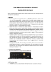
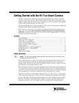
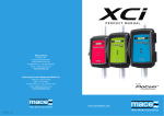
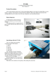
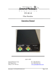
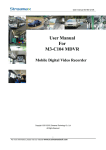
SVC400P/SVC800P 4/8 Camera Live Tracking Vehicle DVR Installation Manual Version 1.0 SVC400P/SVC800P - Installation Manual 1. MAIN FEATURES .......................................................................................................................................................... 2 2. PRODUCT OVERVIEW .................................................................................................................................................. 2 3. DIMENSIONS ............................................................................................................................................................... 4 4. PACKAGE CONTENTS ................................................................................................................................................... 5 5. MOUNTING AND ENVORNMENTAL REQUIREMENTS ................................................................................................. 5 6. INSTALLATION TOOLS .................................................................................................................................................. 5 7. INSTALLATION INSTRUCTIONS .................................................................................................................................... 6 8. CONNECTING THE POWER ......................................................................................................................................... 6 9. CONNECTING INPUTS AND OUTPUTS......................................................................................................................... 7 9.1 The A/V Cable Definition (Video Input/ AV output) .......................................................................................... 7 9.2 Specifications for the SENSOR BOX (sensor inputs and outputs) ...................................................................... 8 9.3 Specifications for 485 and 232 serial ports........................................................................................................ 9 10. WORKING STATUS ...................................................................................................................................................... 10 11. INERTIAL SENSOR CONNECTION ............................................................................................................................... 11 12. HDD INSTALLATION .................................................................................................................................................... 11 13. SIM CARD INSTALLATION ........................................................................................................................................... 12 1 SVC400P/SVC800P - Installation Manual 1. MAIN FEATURES The SVC400P/SVC800P is an embedded Mobile Digital Video Recorder (MDVR) that provides the perfect surveillance solution for vehicles. It features H.264 video compression which guarantees a high quality image, high compression rate for smooth and fast network transmission. A special movable plastic HDD case allows you remove and access the stored data easily and efficiently. . The powerful CMS software provides • • • • • Remote Monitoring GPS Locations Local Recording Remote Downloading Alarm Report System Additionally the MDVR’s CMS is set-up to provide automatic services for the protection of its data such as recovery, datamonitoring and backup for all its critical data. 2. PRODUCT OVERVIEW Front View Definition for LED and connector on front panel: Items Name Description Video Output VIDEO_OUT Video output HTR Heater LED. SD Flash when the SD is writing and reading. REC for record, ON means recording normal GPS For GPS signal NET For displaying the network status POWER For power, when the MDVR is powered, the LED will be lit HDD If the MDVR install HDD is working fine. The LED will be lit ERR If the MDVR has errors such as no HDD, the LED will be lit ALARM If the MDVR has triggered an alarm, the LED will flash VLOSS It will flash if video loss happens LED 2 SVC400P/SVC800P - Installation Manual IR receiver IR For receive the signal of remote control System Information DEBUG Testing series port for MDVR device USB Interface USB2.0 USB2.0 for record files back up or firmware update Lock LOCK Need to lock the HDD case before boot up the MDVR, Otherwise, the MDVR can not boot up. When the MDVR is working, unlock the HDD case and then MDVR will standby. Rear View Items WI-FI ANT connector GPS ANT connector Name WI-FI Description For connecting the WIFI ANT GPS For connecting the GPS ANT EDGE For connecting the 3G/EDGE/GPRS ANT Power input DC8-48V For connecting power input Network port RJ45 Network port to make sure the MDVR can go online 3G/EDGE/GPRS ANT connector A/V input and output and alarm output A/V Integrated input A/V Power supply for camera I/O Input and Output I/O I/O sensor input and output EXTEND Interface EXTEND For extend function, such as RS485 and RS232 serials port. 3 SVC400P/SVC800P - Installation Manual 3. DIMENSIONS 4 SVC400P/SVC800P - Installation Manual 4. PACKAGE CONTENTS Please ensure that the SVC400P/SCV800P’s box includes the following items: MDVR’s Recording Module and Mounting Assembly Video Input/ AV output cable Power cable USB Cable Screws for installing the unit A set of keys for locking and/or unlocking the HDD case and a fuse Handheld IR remote control (batteries not included) Installation bracket Accessories available for the SVC400P/SCV800P include the following: Alarm Input Box GPS Module and Antenna 3G Module Wifi Module Din Plug to BNC Socket Adapter Locking Box (SVA400A) (SVA400G) (SVA400T) (SVA480W) (SVA480C) (SVA400L) 5. MOUNTING AND ENVIRONMENTAL REQUIREMENTS To ensure the MDVR operates efficiently and within the product warranty compliance, please adhere to all following installation instructions: Power: It is recommended that the MDVR be connected to the vehicle ignition. Battery power is used only when the vehicle is running. The MDVR could drain any vehicle battery over time if the ignition is not turned off. Connection: Connect only to appropriate power supply and ensure proper grounding of the circuit. Moisture: Protect unit and connections from environmental sources of moisture and liquid spills. Temp: Do not install where unit temperature will exceed F140°F (60°C), fall below -20°F (-28°C) or store the unit where temperatures rise above 175°F (80°C). Avoid direct exposure to sunlight. Ventilation: Provide sufficient ventilation with a minimum of 6 inches cooling clearance to ensure proper operating temperature for the unit. Vibration: If necessary, provide additional shock mounting to prevent damage and wear by excessive vibration. Clearance: Front clearance of 8 inch is required to slide the recording module from the mounting assembly. Wiring: Install where mounting assembly wires have sufficient clearance and will not be crimped or subject to wire insulation damages due to vibration. Access: Secure the MDVR so that passengers or drivers cannot tamper or damage the unit, cameras, wires or other accessories. Do not mount where access to any other vehicle component will be restricted. Injury: Install the unit, cameras, accessories and wires so that no injuries can be caused through impact with equipment during vehicle operation. Ensure that all transportation regulations are followed to avoid passenger injury should they come in contact with the installed equipment. 6. INSTALLATION TOOLS Please ensure that you have the following tools available prior to commencing an installation: Drill and bids Screws/bolts and vibration dampening washers as appropriate for mounting Wire cutters and wire connectors Test for voltage and electric current 5 SVC400P/SVC800P - Installation Manual 7. INSTALLATION INSTRUCTIONS Follow these guidelines when installing MDVR’s: Unpack all components provided in the package. Disconnect any source of power supply and/or devices. Locate a proper spot to install the SVA400L and install a built-in vibration absorber if required. Locate a reliable electrical ground point in the vehicle. All wires and connections should be gathered to the back of SVA400L. Connect to a power source and turn on the vehicle ignition to test the unit. Observe completion of the unit power-up procedures as described in section labelled as "System Startup and Shutdown". Meet all legal requirements for installing and/or operating a video surveillance, such as labelling all the essential information on the MDVR. Video surveillance statues vary across nations; please abide to the local statues. 8. CONNECTING THE POWER FOR THE MDVR’S Wire Description Positive Input (Red) Positive wire. Should be connected to the positive terminal of the battery (DC +12V) GND Input (Black) Negative (ground) wire. Should be connected to the negative terminal of the battery. Ignition Signal Input (Yellow) Connect with vehicle ignition to let the system start up (need provide +12V/24V DC power as signal ON/OFF) The Ignition Switch is very important. Only once the MDVR’s is to the ignition wire can it can boot up The following conditions must be fulfilled at the same time for MDVR’S to boot up: 1. 2. If you don’t use ignition line, please connect it to positive terminal, otherwise the device can’t startup. Make sure the HDD installation is correct, since the MDVR will try to detect the HDD first before boot up. If the HDD installation is wrong, then the unit will continuously try to detect the HDD and MDVR’s will not complete the boot-up process. 6 SVC400P/SVC800P - Installation Manual 9. CONNECTING INPUTS AND OUTPUTS 9.1 The A/V Cable Definition (Video Input/ AV output) Specifications for the PINs: A/V Cable interface definition: Item Name Explanation A/V input is a 4-pin female connector; 4CH machine has 4 A/V inputs, 8CH A/V INPUT VIN1~VIN4 machine has 8 A/V inputs. Feet 1 is for 12V power input, feet 2 is for GND, feet 3 is for audio input, and feet 4 is for video input. A/V OUTPUT AV OUT A/V output is a 4-pin male connector; feet 1 is for 12V power input, feet 2 is for GND, feet 3 is for audio input, and feet 4 is for video input. 7 SVC400P/SVC800P - Installation Manual 9.2 Specifications for the SENSOR BOX (sensor inputs and outputs) SENSORs 1-6 are the inputs for I/O sensors, SENSOR OUT is for sensor output connection SPEED- and SPEND+ are for speed sensor, which connect to the speed pulse of the vehicle. Firstly, follow the steps of GUI > SETUP > EVENT > SENSOR; then, enable the sensor switch; and make sure the alarm switch is ON, as shown below: The MDVR has 6 Alarm inputs and 2 Alarm outputs. All alarm inputs are I/O PWL which can reflect various vehicle statuses such as braking, turning left etc. A schematic diagram of the alarm input ‘braking’ is shown below; when the brake is applied the MDVR will detect the I/O PWL, the alarm LED will light up (or flash) and will record this event. 8 SVC400P/SVC800P - Installation Manual +24V Stoplight Braking vane Connect to MDVR’S sensor input All alarm outputs are PWL outputs, drive ability is 200MA, and the voltage is +12V, if you need more than that, please connect to an external relay. An alarm output photoelectric wiring diagram is as follows: MDVR’S Alarm output 24V 9.3 Specifications for 485 and 232 serial ports There are two 485 serial ports and two 232 serial ports, the functions are the same. These serial ports can connect to accessories purchased from Shenzhen Streaming Video Technology, such as the inertia sensor (acceleration), control panel, PTZ, station announcement, and the card reader etc. Please Note: 485A means 485+, 485B means 485SETUP > PERIPHERAL > EXT.COM SETUP MODE: There are STANDARD and BUS MODE two options, when select standard mode, you can select each external port for each COM, when select Bus mode, COM1 is station announcement, COM2 is amplifier board, unchangeable, COM3 and COM4 is changeable. Please Note: COM1 means 232RXD-1, COM2 means 232RXD-2, COM3 Means 485-1, COM3 Means 485-2. PTZ is recommended connect to COM3 or COM4. 9 SVC400P/SVC800P - Installation Manual 10. WORKING STATUS When device started up, please check the LED, HTR is ON means device has built-in heater, POWER is ON means the power is normal, ERR is ON means there is no HDD or some other hardware errors, NET is ON means the net module is normal, VIDEO LOSS is ON means there is video loss, if all the LED always flashing, and no live view, that means there is something wrong with MDVR, please contact with the sales. Please Note: when MDVR has started up, and only POWER LED is on, and no live view output, please make sure you have locked the HDD box. 10 SVC400P/SVC800P - Installation Manual 11. INTERTIAL SENSOR CONNECTION If the MDVR’s is connected to the inertial sensor then you track its features in the unit’s Graphical User Interface (GUI) as following (SYSTEM > SENSOR > ACCELERATION; and then press check): If you move the inertia sensor, then the values for X/Y/Z will change. After installing the inertia sensor, make sure that the ENABLE switch is turned on. Then press CHECK to verify its current values (all the values will be defaulted to 0). 12. HDD INSTALLATION Open the lock with the key in fittings box, remove the HDD box and screws, and then open the box, as the picture below: Hard disk cartridge Install the foam pad on both sides. Since there is no screw here, we are use rubber cover and foam pad as a vibration absorber. One side of the box is a blue foam pad; the other side is two yellow foam pads. Put the rubber cover on both sides of the SATA HDD, the side with a rubber band should be near to the circuit board. Connect the cable (please make sure the data cable is connected properly). Put the cover back-on and then refit the screws. Please Note: Please lock the HDD after successfully installing the HDD, otherwise the MDVR will not start-up. 11 SVC400P/SVC800P - Installation Manual Install the vibration absorber foam HDD installation 13. SIM CARD INSTALLATION When the device has built-in 3G wireless module that support the wireless network communication the user will need to install the a SIM Card, as detailed in the image above: Remove the HDD box and the SIM Card cover Carefully insert the SIM card in place, re-attach the SIM Card cover and place the screws and HDD box back as normal, ensuring that you have connected the 3G antenna. Follow the steps of GUI > SETUP > NETWORK > MOBILE NETWORK; select the mode type for the wireless module you have got, as well as APN and the access number. The device will restart after all these have been setup. 12 SVC400P/SVC800P - Installation Manual Check the setup status: Finally, we can check the status of the SIM card by pressing ENTER in the live view after unit has restarted. You will find the status information for unit (see the screen below) which includes signal, network, dial up status and CMS connection status. 13