1
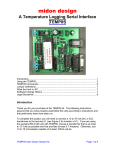
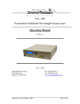
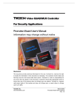
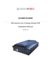
FST-001-B
Fiber Stretcher
Operation Manual
April 6, 2005
General Photonics Corp.
5228 Edison Ave.
Chino, CA 91710 USA
Document #: GP-UM-FST-001-B-10
Ph: (909) 590-5473
Fax: (909) 902-5536
www.generalphotonics.com
Page 1 of 9
Table of Contents:
Caution
3
Section 1
Specifications
4
Section 2
Overview
5
Section 3
Operating Instructions
7
Section 4
Technical Support
9
Document #: GP-UM-FST-001-B-10
Page 2 of 9
IMPORTANT SAFETY NOTE
The FST-001-B PCB board inside the enclosure can produce hazardous voltages and
currents. The DC voltage on the board can reach 150 V. Never open the cover of the
FST-001-B or touch any part of the board or cable connectors when electric power is on.
CAUTION
The maximum peak current to each channel of the FST-001-B is 60 mA. However, the
maximum current available to each channel will depend on operating conditions.
Because the on board DC/DC converter output current rating is 80 mA, the sum of the
currents to the four channels cannot exceed 80 mA. If each channel is operated
sequentially, the current limit per channel is 60 mA. However, if all 4 channels are in
operation simultaneously, the maximum continuous operation current rating for the FST001-B is 20 mA per channel. A severely distorted output waveform indicates that the unit
is being operated at a current that exceeds the current rating. If a sinusoidal waveform is
used as a driving source, the user should check Section 3.2.1 in this manual to make sure
that the output voltage and driving frequency are within the designed safe operation
range.
Document #: GP-UM-FST-001-B-10
Page 3 of 9
Section 1. Specifications:
Physical Features:
External analog input connector
External digital input connector
10-pin AMP type with 0.1” pitch
20-pin AMP type with 0.1” pitch
Max Ratings:
Max. output voltage
Max. output current
Max Input Signal Voltage
140 VDC
20 mA/channel all channels (continuous)
60 mA/channel single channel (continuous)
60 mA per channel (peak current limit)
5V
Optical Characteristics:
Operating wavelength
System insertion loss1
PDL
Optical power handling
Fiber Input/Output Connectors
1550 nm standard
<0.2 dB
<0.1 dB
>1000 mW
FC/PC, FC/APC, SC/PC, SC/APC2
Electrical Characteristics:
Input Analog Signal Voltage Range
Input Resistance
Digital input
140V Output Response Time
15V Output Response Time
Output Voltage Range
Output Impedance
External Input Gain
Noise
-3dB Bandwidth3
Operating Temp.
Storage Temp.
0 to 5V
≥20 kΩ
TTL, 12-bit data, 4-bit control
< 400 µs rise/fall time
65 µs rise/fall time
0-140V DC
50 ohms
30 V/V ± 1%
< 40 mV (RMS)
16 kHz
0 to 40º C
-20 to 60º C
Required Power Supply:
Standard
+ 12V DC / 1.2A
Note:
1. Measured without connectors.
2. Per customer specification.
3. The bandwidth is measured at 140V output with no load. Any piezoelectric element
added to the output may decrease the bandwidth. The –3 dB bandwidth is defined by the
frequency at which the output peak-to-peak voltage drops from 140 V to 100 V (~ 0.707
× 140 V).
Document #: GP-UM-FST-001-B-10
Page 4 of 9
Section 2. Overview:
The FST-001-B is a precision multiple channel fiber stretcher with four piezoelectric
actuators that can be driven individually for high resolution or collectively for large
stroke. Stretching the fiber causes a change in both the length and index of refraction of
the fiber, resulting in a change in optical path length. Sample applications include optical
path length compensation and various sensing and interferometric applications, including
medical imaging.
The FST-001-B accepts both analog and digital control signals. It has a closed loop gain
of 30V/V, so analog input voltages of 0-5V are sufficient to cover the full range of the
stretcher. The external analog control voltage can be supplied by any stable voltage
source, including function generators, DAC output, or DC power supplies. For digital
control applications, the FST-001-B can be controlled by a 16-bit parallel TTL digital
signal from any logic circuit. The digital signal controls each channel individually.
The standard board of the FST-001-B operates at +12V. A 12V power adapter that plugs
into a standard wall power supply is provided.
2.1
Interface descriptions
Analog and digital input connectors are mounted on the rear panel of the FST-001-B, as
shown in Figure 1. The analog and digital input connectors are a 10-pin and a 20-pin
AMP type, respectively. All connectors on the FST-001-B have standard 0.10 inch (2.54
mm) pin separation. The pinout diagram is shown in Figure 1.
TTL Input
19 17 15 13 11 9 7
Analog Input
5
3
1
20 18 16 14 12 10 8 6 4 2
9
7
5
3
1
10 8
6
4
2
Figure 1 Analog and digital input connector configurations.
The pin assignments for analog and digital input connectors are summarized in Table 1
and Table 2, respectively. The analog input connector uses 5 independent connections,
while the digital connector has 18 independent connections.
Document #: GP-UM-FST-001-B-10
Page 5 of 9
Table 1: Analog input connector pin assignment list
Pin number
1
2
3
4
5
6
7
8
9
10
Assignment
VIN1
VIN3
AGND
AGND
VIN2
VIN4
AGND
AGND
AGND
AGND
Function
Channel 1 input
Channel 3 input
Analog ground
Analog ground
Channel 2 input
Channel 4 input
Analog ground
Analog ground
Analog ground
Analog ground
Table 2: Pin assignment for digital input connector
Pin
number
1
2
3
4
5
6
Assignment
/WR
/CS
NC
A0
A1
DB0
7
8
9
10
11
12
13
14
15
16
17
DB1
DB2
DB3
DB4
DB5
DB6
DB7
DB8
DB9
DB10
DB11
18
19
20
DGND
DGND
NC
Document #: GP-UM-FST-001-B-10
Function
Read/Write
Chip select, negative active
Not connected
Channel control bit 1
Channel control bit 2
Digital signal least significant bit
(LSB)
Digital signal bit 2
Digital signal bit 3
Digital signal bit 4
Digital signal bit 5
Digital signal bit 6
Digital signal bit 7
Digital signal bit 8
Digital signal bit 9
Digital signal bit 10
Digital signal bit 11
Digital signal most significant bit
(MSB)
Digital ground
Digital ground
Not connected
Page 6 of 9
Section 3. Operation Instructions:
Important Safety Notes
The FST-001-B PCB board inside the enclosure can produce hazardous voltages and
currents. The DC voltage on the board can reach 150 V. Never open the cover of the
FST-001-B or touch any part of the board or cable connectors when electric power is on.
3.1 Getting started
Unpacking
The FST-001-B is shipped with a [email protected] AC/DC power supply, analog and digital
input cables, and user manual.
Initial setup
1.
2.
3.
Plug in +12V DC power supply on the rear panel.
Connect analog or digital input cable to the appropriate analog or digital
control signal source before connecting analog or digital input connectors to
the FST-001-B.
Connect input and output fibers to FST-001-B. It is important to clean the
fiber connectors using industry standard procedures before connecting them.
In the case of a high power laser source, turn off optical power source before
connector cleaning.
Note: For interferometric applications, make sure that all fibers are fixed in
position and cannot move during measurement. This can be done by taping
them to the optical table.
3.2 Operation
The FST-001-B board can be operated under either analog or digital control modes.
These two modes cannot be operated at the same time unless one of the control signal
groups is set to zero.
3.2.1
Analog control mode operation
To operate the FST-001-B in analog control mode, a multi-channel (at least 4 channels)
DC or AC signal generator is required. Typical signal sources are function generators,
DC power supplies, digital-analog-converter output lines, computer controlled analog
output boards, etc. Analog signals can be applied to all channels simultaneously.
1.
2.
Set the analog signal source at or near zero or its lowest output level. Connect
analog signal source to analog input connector on the rear panel (use 10-pin
input connector cable; refer to Figure 1 for pinout diagram).
Turn on the +12V DC power supply (power switch on front panel).
Document #: GP-UM-FST-001-B-10
Page 7 of 9
3.
4.
Adjust voltage applied to the analog input connector to set voltage at the
desired level. The input analog signals are amplified by a factor of 30. Never
apply a voltage higher than 5V to the FST-001-B. Do not apply a negative
input voltage to the FST-001-B. In general, the +12V current should be less
than 1.0 A during continuous drive operation.
If a function generator is used, make sure that the applied signal frequency
and amplitude do not overload the circuit. To avoid damage to the amplifier
board, periodic analog inputs (such as from a function generator) should meet
the following conditions:
a. For one channel operating alone, or for two channels (channels 1 and 3 or
2 and 4) operating simultaneously, input conditions must satisfy:
BW = f * V < 2.5 kHz · V.
For example, if peak-to-peak input voltage V = 2V, input frequency f must
be < 1.25 kHz
b. For three or 4 channels operating simultaneously, or if channels 1 and 2 or
3 and 4 are operating simultaneously, input conditions must satisfy:
BW = f * V < 1.25 kHz · V.
For example, if peak-to-peak input voltage V = 2V, input frequency f must
be < 0.625 kHz.
5.
3.2.2
Turn off the power supply when not in use.
Digital control mode operation
Unlike the analog control mode, the digital control signals operate sequentially. The
digital control signal is applied to one channel at a time. Of the 20 digital control signal
lines, 17 are used for digital control signals, as listed in Table 2. Of the 17 control
signals, 12 lines are used to load a 12-bit parallel voltage level control signal to a selected
channel. The other 5 lines are used for data traffic control. Therefore, a parallel output
signal source such as a digital input/output (DIO) board or computer parallel port is
required to perform digital control. An initialization step is required when starting digital
control mode operation.
1.
2.
3.
4.
5.
Connect digital input connector to FST-001-B after initial setup steps.
Turn on +12V DC power supply (power switch on front panel).
Launch an application program that generates appropriate digital control
signals.
An initialization step is required at the beginning of digital control. The
initialization process sets the following lines:
W/R
change from 0-1-0-1
DB0—DB11
from 0-1-0
A0, A1
from 0-1-0
CS
from 0-1-0-1
The initialization process can be performed in parallel.
Digital control of output voltages:
a. Change W/R from 1 (default) to 0 (load data mode).
Document #: GP-UM-FST-001-B-10
Page 8 of 9
b. Load data to DB0-DB11.
c. Set A1, A0 to select output channel according to Table 6.
Table 6: Output channel selection control assignment
Channel
1
2
3
4
A1
0
0
1
1
A0
0
1
0
1
d. Change /CS (chip select) from 1 (default) to 0 (select chip) and back to 1
again. This feature is very useful when multiple FST-001-B units are in
use. The user can apply the /CS signal to select different boards and to
share the data lines.
e. Maintain W/R at 0 and repeat steps (b) to (d) to operate another output
channel.
f. If reset is needed, change /Reset to 1.
g. Turn off power supply when finished.
Section 4. Technical Support:
The FST-001-B can be serviced only by manufacturer authorized personnel. There are
no user serviceable components in this system.
General Photonics is committed to high quality standards and customer satisfaction. For
any questions regarding the quality and the use of the FST-001-B, or future suggestions,
please contact General Photonics Corporation at (909)-590-5473 (telephone) or (909)902-5536 (fax), or by e-mail at [email protected]. General Photonics will
respond to all customer questions within 24 hours during regular business hours. You
can also write to:
General Photonics
5228 Edison Avenue
Chino, California 91710
USA
Document #: GP-UM-FST-001-B-10
Page 9 of 9