1
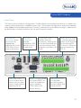
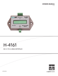
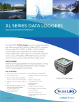
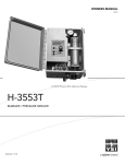
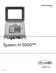
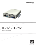
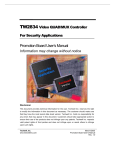
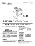
System H-5000™
GETTING STARTED GUIDE
V.1.41
This guide is a brief overview of the System 5000™ data logger and its basic features.
Please refer to waterlog.com/5000 or contact your sales representative for more
information. Manuals, new firmware updates, brochures, technical notes, and supporting
software are available on waterlog.com as updated.
For additional assistance, please contact us at +1.435.753.2212 or [email protected]
System 5000 Getting Started Guide
Chapter 1: System 5000™ Overview.............................2
Unpacking Your System 5000....................................... 3
Chapter 2: System 5000™ Software .............................4
The Main Menu............................................................... 5
Screen Design and Layout............................................ 6
Setting the Site ID........................................................... 7
Setting the Data and Time............................................. 8
A Simple Example.......................................................... 9
Creating a Task (Battery)............................................ 9
Selecting an Input/Source (Battery)..........................10
Adding an Output/Destination (Log To File)........... 11
Adding Slopes, Offsets and Custom Functions...... 12
Enabling/Disabling Scanning................................... 14
Chapter 3: System 5000™ Hardware..........................15
Top View.......................................................................... 16
Front Panel.......................................................................17
USB Ports......................................................................18
Ethernet Port............................................................... 18
RS-232 Ports................................................................ 18
SDI-12 Ports................................................................. 18
Switched +12 Volt Excitation.....................................19
Power Connection...................................................... 19
AC Input....................................................................... 19
Digital I/O.................................................................... 19
Analog Input Section..................................................19
4 to 20 Milliamp Output............................................ 20
Additional Support........................................................ 21
1
01 /
2
SYSTEM 5000™
OVERVIEW
System 5000™ Overview
The System 5000™ is the next generation
data logger / data collection platform (DCP)
using a touch screen interface for standard
and advanced data logging applications.
Optional plug-in modules allow the data
logger to be configured for a wide variety
of monitoring, data logging and SCADA
applications. Current option modules include:
• Analog/Digital expansion module
Multiple configurations are available using
additional expansion cards and an internal
GOES transmitter.
Top View
Unpacking Your System 5000™
When unpacking the System 5000™, make
sure all the components ordered are received
and are in working condition. The basic
configuration of the System 5000™, includes
the following:
Main Deliverables:
• The System 5000™ base unit
• Sensor connection terminal blocks
• Hard copy of the “Getting Started Guide”
• 6FT USB 2.0 Cable (Data Cable)
Optional Items:
• Expansion Module(s)
• Cables
• Sensors
• SD Memory Card
• USB Thumb Drive
3
02 /
4
SYSTEM 5000™
SOFTWARE
System 5000™ Software
The System 5000™ takes a new approach to data logging. During setup, measurement parameters
are assigned logical names (labels) such as AirTemp or Battery. These names are referred to as Tasks
in the System 5000™. Each Task can be assigned an input or source, such as an SDI-12 sensor or an
A/D channel, as well as one or more output or destination, such as a log file or GOES transmission.
The value retrieved from the input becomes the Task’s primary value and will be passed along to any
outputs assigned to that Task. In this manner, inputs and their values can be easily identified by their
Task names in both simple and more advanced setups.
The Main Menu
All setups and configurations can be
performed using the built-in touch screen
display. After the System 5000™ has fully
booted, touch anywhere on the screen to turn
the display on. The screen to the right will
appear.
Manage Tasks
The Manage Tasks section is used
to set up and maintain the System
5000™’s Inputs and Outputs (Tasks).
Data File Manager
The Data File Manager section is used to view, copy, rename, and delete data files on the System
5000™ or an attached USB thumb drive or SD memory card. System configuration saving/
loading, Firmware updating, and other options are also performed here.
System Setup
The System Setup section is used to manage general system options and system-wide settings
such as the Site ID, date, and time.
Turn Display Off
The Turn Display Off button turns off the touch screen. To turn the display on again, simply touch
anywhere on the screen.
Enable / Disable Scanning
The Scanning indicator shows if scanning is enabled or disabled. The indicator is green when
scanning is enabled and red when disabled. The scanning status (running of Inputs and Outputs)
can be toggled by pressing this button.
5
SYSTEM 5000™ SOFTWARE
Screen Design and Layout
The images on page 16 show the basic layout for all screens used within the System 5000™. All
screens contain a header, consisting of the current screen’s title along with a “Help” button, and
footer, containing either an OK/Cancel button combination or a unique function button and Exit
button.
Help Button
The “Help” button is available on all
screens within the System 5000™. The
“Help” button can provide valuable
insight regarding options on the
current screen.
OK Button
Screens with “OK/Cancel” buttons
have options that may need to be
saved before returning to the previous
menu. The “OK” button saves any
changes to the current screen. When
changes are detected, the “OK” label
turns blue.
Cancel Button
The “Cancel” button discards any
changes made to that screen.
Exit Button
Screens with “Exit” buttons save
changes automatically.
Run Task Button
Screens with “Exit” buttons also
contain a unique function button that
applies to that screen only.
6
System 5000™ Software
Setting the Site ID
From the main menu, press the “System Setup” button to open the setup menu. With the “General
Setup” tab selected and the “System Settings” option highlighted, press the “Open” button to enter
the “System Settings” screen.
The System Settings screen allows the
Site ID, Default Error String, and Switched
+12V settings to be modified. Restoring
the System 5000™ to its default settings
can also be performed here.
To set the Site ID, press the “Edit” button
next to the Site ID label.
The expanded Keyboard allows the Site
ID to be set via the touch screen. To erase
the current value (“SiteID”) press the CLR
button and then enter a new ID.
When finished, press the “OK” button, and
“OK” again on the System Settings page
to save the new Site ID. Press the “Exit”
button to back out to the main menu.
7
SYSTEM 5000™ SOFTWARE
Setting the Date and Time
From the main menu, press the “System Setup” button to open the setup menu. With the “General
Setup” tab selected and the “Date & Time” option highlighted, press the “Open” button to enter the
“Date & Time Setup” screen.
The date, date format, and time are set
within this menu.
Notice the two “Edit” buttons used to
set the time and to select a date format.
The date is set by selecting the day in the
displayed calendar.
When setting the new time, press the “OK”
button when the actual time matches
the displayed time. Then press the “OK”
button on the “Date & Time Setup” menu
to save the new time as the system time.
With the time and date set, press the “OK”
button and then the “Exit” button to back
out to the main menu.
8
System 5000™ Software
A Simple Example
To show the ease-of-use of the System 5000™, a simple example will be demonstrated. In this
example the System 5000™ will be set up to log date, time, air temperature, and battery voltage
every 15 minutes.
Creating a Task (Battery)
From the main menu, press the
“Manage Tasks” button to open the
Tasks menu. Setting up a new Task and
adding new sensors should be the
first action taken. Press the “New Task”
button to create a new task.
Notice in the screen that most options
are not accessible because no tasks
have been defined yet.
When the “New Task” button is pressed
on the previous menu, the ‘Edit Task’
submenu automatically opens.
The default Task label is “myTask”. Press
the “Edit Label” button to open the
Keyboard and change the name of the
Task. Use names that will allow the Task
to be easily identified, like ‘AirTemp’
or ‘Battery’. As this Task will track the
battery, set the label to “Battery” and
press “OK” to return to the ‘Edit Task’
screen.
9
SYSTEM 5000™ SOFTWARE
Selecting an Input/Source (Battery)
Once a Task label has been defined,
press “Select Input” on the ‘Edit Task’
screen.
To retrieve the voltage of the battery,
select “Battery Voltage” from the list of
available inputs. Press the “OK” button
to open the Battery Voltage Properties
page.
De-selecting the checkbox at the
bottom of the Select Input screen
causes the “Edit Task” screen to be
displayed rather than the selected
input’s properties page. To edit an
Input’s properties, press the “Edit Input”
button on the ‘Edit Task’ page.
All inputs (and outputs) have unique
settings based on their type. The scan
rate for this Task may be changed
here by pressing the top “Edit” button.
Advanced scanning options as well
as math and data options (e.g. slopes,
offsets, and custom functions) can be
added to the Task as well. A live reading
for most inputs is available above the
“OK” button.
When finished, press the “OK” button
to return to the ‘Edit Task’ screen. The
Task is now configured to retrieve the
current value of the battery. To change
or edit the properties again for the
Task’s Input (Battery Voltage), press the
“Edit Input” button.
Note that only a single source may be used as a Task’s Input (though multiple outputs may be
defined).
10
System 5000™ Software
Adding an Output/Destination
(Log to File)
Once a Task Input has been defined,
press “Add Output” on the ‘Edit Task’
screen.
To log the value of the Task’s Input to a
file, select “Log To File (New Log File)”
from the list of available inputs. This
will create a new log file for the Task to
log to. Press the “OK” button to open
the Log To File Properties page.
If one or more Log files are already
configured, they will appear as options
in the Add Output menu (e.g. “Log To
File (SiteID.csv)”).
A new log file will be named after the
System 5000™’s Site ID and log the
Date, Time, and the Task’s Input value.
To log at a different rate or based
on a condition, the Timed Rate and
Conditional options can be modified.
On the ‘Log To File Properties’ page,
press the “Edit” button next to the
grayed out “Add” button to change
the default log file properties.
The screen to the right defines the
basic options for the data file. The file
may be renamed, previewed, and/or
customized. Additional options can be
found under the Advanced Options
menu via the “Edit Options” button.
When finished editing the log file properties, press “OK” to return to the “Log To File Properties”
page, then “OK” again to return to the ‘Edit Task’ screen.
11
SYSTEM 5000™ SOFTWARE
Adding Slopes, Offsets and Custom Functions
With the ‘Adding an Output/Destination (Log File)’ reference on page 9 as a guide, create a new
task called “AirTemp”, connect a probe to Analog 1 (Vin1, +5Vref, and Agnd), and select “Analog
In” as the Input.
Analog Inputs have many options
available to them including choosing
which input channel(s) to use, how many
samples to take, and whether to impose
a warmup before the measurements are
retrieved. A differential reading may be
used by choosing channels 1-2 or 3-4.
Press the “Edit” button near “Math & Data
Options” to set a slope and offset or use
a custom function.
Many temperature probes require a
basic slope and offset to convert the
raw input voltage to a value in degrees
C or degrees F. A sensor that has a
range of –40.0 to +60.0 degrees C that
corresponds to a 0.0 to 5.0 volt input
will have a slope of 20.0 and an offset
of –40.0.
Press the “Edit” button near the “Slope”
or “Offset” option to change the
respective value.
If using the Waterlog H-377 probe, the
“Custom Function” option should be
used. The H-377 temperature probe is
an inexpensive, yet high quality sensor,
which relies on the data logger to perform higher-level math operations to convert the raw
voltage to a temperature reading. Press the radial button near “Custom Function” and then
12 press the “Edit” button
System 5000™ Software
The ‘Custom Function’ screen is used
for applying simple or advanced
mathematical equations to a Task’s
Input value.
Press the “Functions” button to display
a list of available functions.
Scroll down the list and highlight
“h377c()” or “h377f()” in the list. Press
the “Insert Function” button to add
the function to the Custom Function
equation.
If no parameter or Task is specified
within the parentheses “()”, the Task’s
Input value (labeled as “RawValue”
under the User-Defined Tasks section)
will be used. In other words, h377c() is
equivalent to h377c(RawValue).
Press the “OK” button to save the
changes made to the “Custom
Function”.
Press the “OK” button on the “Math & Data Options” menu to return to the Analog Input properties
menu, and “OK” again to return to the ‘Edit Task’ screen.
To add the “AirTemp” Task to the existing Log File, follow the steps outlined in the ‘Adding an
Output’ section (pg.11).
13
SYSTEM 5000™ SOFTWARE
Enabling/Disabling Scanning
Once the System 5000™ has been set up
as desired, scanning should be enabled.
Press any “OK” or “Exit” buttons necessary
until the “Main Menu” screen is displayed.
The scanning indicator is red when
scanning is Off or disabled. All Tasks as
well as any incoming events will not be
processed when scanning is Off on the
System 5000™.
Press the red scanning indicator or
“Scanning is Off” text to turn scanning on.
All Tasks will now be processed according
to their scan rates. The next scan time is
shown when scanning is enabled.
To disable scanning, simply press the
scanning indicator or “Scanning is On”
text.
14
03 /
SYSTEM 5000™
HARDWARE
15
SYSTEM 5000™ HARDWARE
Top View
Primary access to the System 5000™ Software is managed through the ¼ VGA touch screen display
on top of the unit. The Power and Active LEDs as well as the SD Card slot are all centrally located
around the display.
The “Power” LED
blinks every five
seconds while power
is applied to the unit.
The “Active” LED
illuminates when the
unit is collecting data
or performing other
background tasks.
¼ VGA color
TFT touch
screen display
is used to
view and edit
the system
settings and
configuration.
Top View
The SD memory card
slot is used to transfer
data and other files to
and from the System
5000™.
16
System 5000™ Hardware
Front View
The base system hardware configuration includes digital and analog functionality to support the
majority of the applications needed by most users. The modular design allows expansion modules
to be added for extended capabilities. Functions and features for the different plug-in modules will
be described in the documentation for the specific option module.
USB “device”
connection allows
easy access to
logged data
allowing the System
5000™ to act as an
external disk drive.
USB “host”
connections
provide
support for USB
devices such as
thumb drives.
10/100 BaseT port
provides Ethernet
connectivity, allowing the
unit to be networked and
accessed remotely with a
computer anywhere in the
world.
Upper terminal strip
is used for applying
power to the unit and
for connecting SDI12 sensors. There are
two connectors for
SDI-12.
Front Panel
The “View Status”
button allows quick
access to the system
status screen without
opening the lid.
Two RS-232 ports allow
the System 5000™ to
control serial devices,
such as modems,
GOES radios, and
remote displays.
The lower terminal
strip provides
connection points
for basic digital and
analog sensors.
17
SYSTEM 5000™ HARDWARE
USB Ports
The two USB-A connectors are provided to connect an external USB “Device”, like a USB Flash
drive, for downloading or uploading data to the System 5000™ internal memory. The USB-B
connector is provided to allow a direct connection from the System 5000™ to a computer for
downloading or uploading data and in this case, the System 5000™ is seen as a USB “Device”,
showing up as an external hard disk on the connected computer.
Ethernet Port
The Ethernet port is a 10/100 BaseT port allowing the System 5000™ to connect to a Local Area
Network or to a Wide Area Network (Internet). Remote operation, System 5000™ programming,
and ports listening for incoming connections (e.g. simple web pages) can all be done through
this port.
RS-232 Ports
The two RS-232 ports are provided to connect
to a PC, GOES Transmitter, modem, remote
display, or other standard serial communication
equipment. These ports are configured as a DTE
type of device. This means they will plug directly
into a modem (DCE type device), but will require
a NULL modem adaptor and gender changer if
connected to a PC (DTE type device). The NULL
modem cable crosses the communication lines
allowing two similar devices to communicate.
The pin out for the RS-232 ports is shown to the
right.
SDI-12 Ports
The SDI-12 Ports are provided to
connect SDI-12 compatible sensors.
Standard SDI-12 sensors have a
minimum of three wires, which are
+12V, Data, and Gnd. There are two
SDI-12 ports, as shown above, for ease
of connecting multiple SDI-12 sensors.
18
Serial Port Pin-Out
PIN
DIRECTION
NAME
1
2
3
4
5
6
7
8
9
Input
Input
Output
Output
N/A
Input
Output
Input
Input
Data Carrier Detect
Receive Data
Transmit Data
Data Terminal Ready
Ground
Data Set Ready
Request To Send
Clear To Send
Ring Indicator
(DCD)
(RD)
(TD)
(DTR)
(GND)
(DSR)
(RTS)
(CTS)
(RI)
System 5000™ Hardware
Switched +12 Volt Excitation
The Switched +12 volt excitation is provided to power sensors, and by default, this port is always on.
There are sensors that only need to be powered when being measured. To save power consumption,
this port can be programmed to turn on only during a measurement.
Power Connection
The Power connection is the main System 5000™ power and ground. The power LED on the front
panel will blink every five seconds when power between 10 – 16 volts has been connected.
AC Input
The AC Input is provided to connect sensors that have a low level AC output like wind speed
sensors. A wind speed sensor has at least two connections: Signal (ACIn) and Reference (Dgnd).
Digital I/O
The Digital I/O connections can be
configured independently as inputs or
outputs. In the input mode, the signal has
an internal pull up resistor of 47K Ohms.
This allows a switch closure to ground to
activate the input. It can also be driven
using normal logic levels. As an output,
a 100-Ohm protection resistor limits
the drive capability. The output will still
be about 4.0 volts with a 10.0mA or less
load. When a pair of digital I/O pins is
configured as inputs, they may be used as
a quadrature shaft encoder input.
Analog Input Section
The lower right terminal strip is used for analog input functions. This includes four analog
inputs, two analog grounds, and one +5Vref excitation connection.
19
SYSTEM 5000™ HARDWARE
Analog Input Channels
There are four analog input channels labeled Vin1 to Vin4. The standard input range for all channels
is 0 to 5 volts; however, because the Analog to Digital converter is highly accurate, it can accurately
measure low level ranges as well. Differential measurements can also be made on channels Vin1 and
Vin2 or on channels Vin3 and Vin4.
Analog Grounds
There are two analog ground connection points. In order to preserve signal integrity, it is important
to use the analog grounds only for sensors connected to the analog section. The current flowing
through an analog sensor is relatively small and normally very stable. If a digital sensor has its ground
connection tied into the analog ground, the currents from the digital sensor will flow through the
analog circuitry causing voltage level shifts and noise based on digitalswitching. There should be
sufficient digital ground connection points for the digital sensors. Power grounds should not be
connected to analog grounds.
Switched +5.00 Volt Reference Excitation
The +5Vref output is used for analog sensors requiring a precision reference voltage. The maximum
output current is 10 milliamps. The Analog to Digital converter uses this excitation for
its reference to provide a ratio-metric relationship for sensors using this excitation.
4 to 20 Milliamp (4-20mA) Output
The 4-20mA output connection points are at
the far right of the lower terminal strip. Several
instrumentation applications use sensors that
provide an industry standard 4-20 milliamp output
signal. The System 5000™ data logger / DCP
can output a 4-20mA signal based on any of its
inputs. For example, a user may want to connect
a temperature probe to the System 5000™ and
convert the temperature value into a 4-20mA
output. A temperature probe on Analog Channel
1 that produces a 0 to 5 volt output representing
0 to 100 degrees Celsius could easily be setup to
produce a 4-20 mA output that represents the 0 to
100 degrees. The System 5000™ does not actually
output a 4-20mA signal, but rather controls the
current in an isolated externally powered loop.
The figure to the right shows a basic connection
diagram.
20
System 5000™ Hardware
Additional Support and Documentation
The web page at waterlog.com/5000 will provide ongoing support for the System 5000™ data
loggers and DCP products. This includes additional manuals (e.g. Basic 5000™ User Manual), new
versions of the main manual, new firmware updates, brochures, technical notes, PC support software,
example Basic programs, etc. Support may also be obtained by contacting WaterLOG directly.
21
What Can Xylem Do For You?
Xylem
1) The tissue in plants that brings water upward from the roots;
2) a leading global water technology company.
We’re 12,900 people unified in a common purpose: creating innovative solutions
to meet our world’s water needs. Developing new technologies that will improve
the way water is used, conserved, and re-used in the future is central to our work.
We move, treat, analyze, and return water to the environment, and we help people
use water efficiently, in their homes, buildings, factories and farms. In more than 150
countries, we have strong, long-standing relationships with customers who know us
for our powerful combination of leading product brands and applications expertise,
backed by a legacy of innovation.
For more information on how Xylem can help you, go to www.xyleminc.com
Xylem—WaterLOG
95 West 100 South
Suite 150
Logan, UT 84321 USA
Tel:
+1.435.753.2212
Email:
[email protected]
Internet: www.waterlog.com
©2014 Xylem Inc.
D35 0514