1
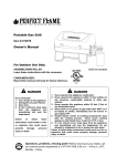
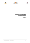
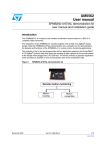
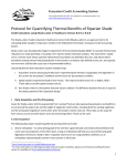
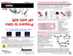
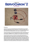
NSSPCM: P12408
User’s Manual
V 001
1
Contents
1.
System Overview................................................................................................................................... 4
2.
Mounting Details................................................................................................................................... 4
3.
Software ................................................................................................................................................ 5
3.1
PCB Firmware ................................................................................................................................ 5
3.2
Diagnostic Utility ........................................................................................................................... 7
3.2.1
Installing the javax.comm library: ......................................................................................... 7
3.2.2
Running the Diagnostic Utility: ............................................................................................. 8
2
Revision
001
Date
2012-05-17
Document Modifications
Modifications
Document Creation.
3
1. System Overview
This manual covers the NSSPCM printed circuit board (PCB) assembly, firmware, diagnostic utility and
mounting information. Documentation for microcontrollers or the development board can be found on
Texas Instruments’ website. NSSPCM design and build documentation should be consulted for specific
information for integrating
ng a payload system with the NSSPCM.
2. Mounting Details
The NSSPCM is capable of either being suspended below the High
High-Altitude-Balloon,
Balloon, or mounted directly
to the existing payload. The standard configuration provides hardware for suspension. In order to
mount the NSSPCM directly to an existing payload, the user must supply hardware. The existing payload
must have a mounting configuration consistent with that of the suspension configuration of the
NSSPCM. The suspension hardware can be removed with a scr
screwdriver
ewdriver and a ½ inch wrench. Once
removed, there will be four (4) open holes, each one quarter (1/4) inch in diameter that the user can
utilize to mount the NSSPCM to the existing payload. Recommendations are one half (1/2) inch
diameter stainless steel bolts. The length will be determined by the user.
Figure 1 – NSSPCM Assembly
4
3. Software
The software section is split into two main areas: how to connect a debugger to interact with the PCB
firmware and how to use the Diagnostic Utility to interact with the RS-485 serial communication bus.
3.1
PCB Firmware
This manual assumes that TI Code Composer Studio 5.1.0 is used and the TI MSP430 Launchpad USB
driver is installed.
1. Remove the jumpers from the MSP430 Launchpad.
2. Connect the programming cable to the Launchpad.
a. The yellow wire connects to the TEST pin and the orange wire connects to the RST pin
on the top side of the board marked EMULATION.
b. Connect the other connector so that the black wire is connected to the middle GND pin
on the lower side of the board.
Figure 2 – MSP430 Launchpad
3. Remove the reset jumper from the NSSPCM PCB.
Figure 3 – Reset Jumper
5
4. Connect the programming cable to the NSSPCM PCBA.
a. The first pin is has no wire connected.
b. The second pin is connected to the orange wire (RST).
c. The third pin is connected to the yellow wire (TEST).
d. The fourth pin is connected to the black wire (GND).
Figure 4 – Firmware Programming Cable
5. Open Code Composer Studio 5 and open the NSSPCM Firmware Project.
Figure 5 – Code Composer Studio Project
6. Open main.c and click the Debug Button (
).
7. Code Composer Studio will compile the program and load it into the NSSPCM microcontroller
memory.
Figure 6 – Loading Firmware Dialog
6
8. The debug window will open and the program counter will be initialized to the beginning of the
main function. Press the Play button ( )to begin program operation.
9. Once the program is running in the debugger, it is safe to disconnect the MSP430 Launchpad
from the NSSPCM PCB and replace the reset jumper for normal operation.
3.2
Diagnostic Utility
This manual continues under the assumption that Eclipse Helios is installed and the selected Java
Runtime Environment is 32-bit JRE 6.
3.2.1
Installing the javax.comm library:
1. Download the javax.comm library and driver by downloading the javax-comm.zip file from the
NSSPCM EDGE webpage.
2. Copy the comm.jar, javax.comm.properties, and win32com.dll to the following locations (or
equivalent):
a. C:\Program Files\Java\jre6\bin
b. C:\Program Files\Java\jre6\lib
c. C:\Program Files\Java\jre6\lib\ext
Note that this location may need to be Program Files (x86).
3. Copy the win32comm.dll to C:\Windows\system32
7
3.2.2
Running the Diagnostic Utility:
Figure 7 – Diagnostic Utility Hardware
1. Assemble the RS-485 interface (when using the MSP430 Launchpad as a UART):
a. Connect Pin 1 (RO) of the MAX3483 RS-485 Driver IC to P1.1 (TXD) on the Launchpad.
b. Connect Pin 4 (DI) of the MAX3483 RS-485 Driver IC to P1.4 on the Launchpad.
c. Connect Pins 2 (RE) and 3 (DE) MAX3483 RS-485 Driver IC to P1.6 on the Launchpad.
d. Connect VCC and GND to the MAX3483 RS-485 Driver IC.
Figure 8 - MAX3483 RS-485 Driver IC Pinout
2. Connect the B pin on the MAX3483 RS-485 Driver IC to the black wire (B) of the NSSPCM’s
communication cable. Connect the A pin on the MAX3483 RS-485 Driver IC to the red wire of the
NSSPCM’s communication cable.
3. Place a 120 Ohm resistor across the MAX3483 RS-485 Driver IC A and B pins.
Figure 9 – RS-485 Serial Assembly
8
4. Open Eclipse and open the NSSPCM GUI project.
Figure 10 – Eclipse Project
5. Expand the src and View folders and open nsspcmGUI.java. Click on the green Run button.
Figure 11 – Eclipse Run Button
6. Select the COM port connected to the NSSPCM serial interface.
Figure 12 – COM Port Selection
7. When the Diagnostic Utility opens, click the Ping button of the Update Status button to verify
that the communication link is active.
9
Figure 13 – Diagnostic Utility
8. To enable the ability to log displayed values to a comma separated file, click the Enable Logging
button or the Save Log To button. Once a log file has been specified, logging can be enabled or
disabled by clicking the Enable Logging or Disable Logging button.
Figure 14 – Save Log File dialog box
9. The logging feature produces a comma separated value (CSV) file which can be easily imported
into Excel for chart creation.
Figure 15 – Log File opened in Excel
10
10. To enable the ability to automatically get the status of the NSSPCM, use the dropdown box to
select an interval and then click the Set Auto-Update button. To disable the auto-updater,
choose Off from the dropdown box and click set Auto-Update.
Figure 16 – Auto-Update selector
11