1
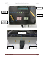
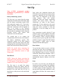
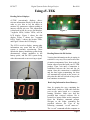
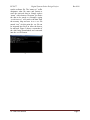
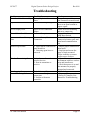
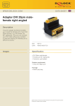
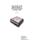
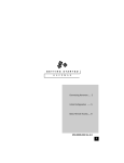
ECE 477 Digital Systems Senior Design Project Rev 8/09 Homework 13: User Manual Team Code Name: eV-TEK Group No. 2 User Manual Outline: Brief (marketing-style) product description Product illustration annotated with callouts for each control/display Product setup instructions Product use instructions Product troubleshooting instructions Evaluation: SCORE DESCRIPTION Excellent – among the best papers submitted for this assignment. Very few corrections needed for version submitted in Final Report. Very good – all requirements aptly met. Minor additions/corrections needed for 9 version submitted in Final Report. Good – all requirements considered and addressed. Several noteworthy 8 additions/corrections needed for version submitted in Final Report. Average – all requirements basically met, but some revisions in content should 7 be made for the version submitted in the Final Report. Marginal – all requirements met at a nominal level. Significant revisions in 6 content should be made for the version submitted in the Final Report. Below the passing threshold – major revisions required to meet report * requirements at a nominal level. Revise and resubmit. * Resubmissions are due within one week of the date of return, and will be awarded a score of “6” provided all report requirements have been met at a nominal level. 10 eV-TEK User ManualInclude this sheet as a cover page for your report Page 0 ECE 477 Digital Systems Senior Design Project Rev 8/09 eV-TEK Telemetry for Electric Karts User Manual eV-TEK User Manual Page 1 ECE 477 Digital Systems Senior Design Project Rev 8/09 Table of Contents Welcome to eV-TEK…………………………………………………………………………3 Product Illustration…………………………………………………………………………...4 Set-Up………………………………………………………………………………………...6 Using eV-TEK……………………………………………………………………………......8 Troubleshooting………………………………………………………………………………10 eV-TEK User Manual Page 2 ECE 477 Digital Systems Senior Design Project Rev 8/09 Welcome to eV-TEK Thank you for purchasing eV-TEK! eV-TEK, or telemetry for electric karts, is a tool for collecting and transmitting vehicle parameters in a race situation. This product is designed to work with electric go karts. It will provide you, the user, with the ability to monitor race critical kart information such as speed, battery life, lap count, and motor variables. This information is then wirelessly transmitted to the pit crew, allowing the team to monitor real-time kart parameters. When properly used, this product should allow the user to gain a competitive edge in race situations. eV-TEK User Manual Features Inductive Speed Sensor – Robust design gives you an accurate kart speed measurement under varying track conditions. On Board GPS – Provides lap count for pre-programmed track layouts. Wireless Transmitter – Sends monitored data to the pit crew to allow for real-time kart monitoring. Data Logger – Stores all monitored data on the kart for later retrieval and analysis. USB Connection – Allows for easy data retrieval from the main system. Battery Monitoring System – Monitors individual cell voltages as well as pack current, allowing for a running total of current pack charge. Also, estimates laps remaining before battery depletion. Independent Battery – Main control system powered using an independent battery. This allows for uninterrupted system use during kart “refueling”. Driver Displays – A combination of digital and analog displays provide key information to the driver in a method that is easy to read. Motor Monitoring – Motor voltage and current draw are measured to ensure that race regulations are met. Motor temperature is also measured to ensure kart safety. Page 3 ECE 477 Digital Systems Senior Design Project Rev 8/09 Product Illustration Communication Line to Main Board Connection to Battery Pack Illustration 1: Battery Monitor eV-TEK User Manual Page 4 ECE 477 Digital Systems Senior Design Project Rev 8/09 LCD Display LED Status Indicators Analog Dials 7-Segment LED Displays Illustration 2: Main Board/Package Front View 25-Pin Connection Port to Rest of System GPS Antenna Connection eV-TEK User Manual Wireless Antenna Connection Illustration 3: Main Board/Package Bottom View Page 5 ECE 477 Digital Systems Senior Design Project Rev 8/09 Set-Up Note: eV-TEK recommends product installation be performed by a certified kart dealer. Battery Monitoring System: The first step is to ensure that the proper connection is made between the battery pack and the battery monitoring system itself. This connection consists of a 15 pin malefemale connection. There is only one way in which the connection will fit together so there is no reason to fear incorrect orientation. Once connected, make sure that the two ends are properly secured using the provided screws. This ensures that connection is not lost during use. The second step is to connect the communication line from the main board to the battery monitoring system. This connection consists of an RCA (Phono) connector. Insert the male end of the cable coming from the main board firmly into the female end located on the battery monitor. NOTE: Be careful when connecting the battery monitoring system to the battery pack as this connection consists of high voltage lines. Main Board: NOTE: Ensure the battery powering the main board is fully charged before using the eV-TEK product. Charge the battery using a standard 12Vdc Lead-Acid battery charger. The first step is to make the proper connection between the battery and the wiring harness. Ensure that the connection is located in an area that will be free of interference so that power to the main board is not lost. eV-TEK User Manual Next, make sure connection between the GPS and wireless antennas are made to their respective connectors on the main board. Next, make all connections to the main wiring harness. This will include connections from the battery monitoring systems and speed sensor. Once all connections are made to this harness, connect the 25 pin connector to the main board. Make sure to secure this connection using the screws provided so that the connection is not lost during use of the product. Once connection is made with the 25 pin connector power will be applied to the main board. At this point the boot-up sequence will commence. Allow a couple of minutes for the system to power up and for the GPS module to acquire a signal. The GPS module has acquired a signal when its status indicator LED has turned green. Base Station: To use the base station to receive real-time data from the kart, start by booting up the base station software. Once the software has been initialized, wait to receive a wireless connection with the kart transmitter. Once a connection has been made data should automatically begin to display on the base station. Kart: In order to use the kart, run through the start-up procedure provided when purchase of the kart was made. If your model of the eV-TEK product includes integration with the kart itself, then status indicators on the main display will show the current status of the kart. Page 6 ECE 477 Digital Systems Senior Design Project Rev 8/09 WARNINGS: Speed Sensor: The speed sensor utilizes a metal bar attached to the kart drive shaft. During use this bar will be rotating at high speeds. Make sure to keep all objects and body parts clear of this area in order to avoid potential damage or loss of limbs. Battery Monitor: Take great care when making and breaking connections with the battery pack. Due to high pack voltages, a dangerous shock hazard exists. Main Board: Do not operate the main control system without the wireless antennas connected. Operation without the antennas may result in damaged transmitters. Main Board Battery: Be careful not to bridge the connector terminals on the battery. This could result in shock and potential damage to other components. General Warning: This product uses GPS and a 900MHz wireless transmitter. These systems could potentially cause interference with other wireless devices. ALWAYS wear a helmet when operating an electric go kart. eV-TEK User Manual Page 7 ECE 477 Digital Systems Senior Design Project Rev 8/09 Using eV-TEK Reading Driver Displays: eV-TEK conveniently displays driverrelevant information directly to the driver in order to give him or her the ability to monitor key parameters without needing to interact with the pit crew. This information is displayed in four key ways: dial displays, 7-segment LEDs, bicolor LEDs, and an LCD display. Figure 1 shows the dial display, Figure 2 shows the 7-segment LEDs, Figure 3 shows the bicolor LEDs, and Figure 4 shows the LCD display. The LCD is used to display, among other information, any errors that the eV-TEK system is currently experiencing. These include the battery monitoring system being disconnected, voltage anomalies in the battery packs, and the GPS system being either disconnected or not receiving a signal. Figure 1 Figure 3 Figure 4 Reading Data at the Pit Station: Viewing kart information at the pit station in real time is very easy. First, turn on all of the pit station components. Next, boot up the pit station software provided with your eV-TEK product. Then, wait until a connection is established between the kart and the pit station. Once this connection is established and the kart begins transmitting, the data will automatically refresh on the screen. At this point the data will refresh as long as the kart continues to transmit. Retrieving Information from Memory: Figure 2 eV-TEK User Manual Start by opening the case containing the main board. Connect a USB cable from the port on the main board to a computer running Windows. Make sure that the provided data retrieval software file is located in a known folder on the computer. Open the Windows command prompt. Navigate to the folder containing the provided software file. Type in the following command: “ev-tek name.csv”. The “ev-tek” command tells the computer to Page 8 ECE 477 Digital Systems Senior Design Project Rev 8/09 run the software file. The “name.csv” suffix designates what file name and format to store the retrieved data in. Simply replace “name” with whatever file name you desire the data to be stored as. (Example: typing “ev-tek test.csv” will retrieve the data from the memory chip and save it as a .csv file named “test”) At this point the .csv file can be imported into Excel to allow the data to be analyzed. Figure 5 shows a screenshot of the data being downloaded and converted into the .csv file format. Figure 5 eV-TEK User Manual Page 9 ECE 477 Digital Systems Senior Design Project Rev 8/09 Troubleshooting Problem Main Board Not Powered Up Lap Count Failure Driver Display Error Possible Cause Battery Depletion/Connection Error GPS failed to acquire signal General Main Board Error Servo or LED connection failure Software Exception Incorrect or Absent Battery Data Incorrect Battery Monitor Connection Incorrect Speed Data 1. Speed sensor connection to main board lost 2. Detecting agent loose or removed Wireless Transmitting Error 1. Interference from other wireless devices 2. Error in transmitter or receiver Data Logging Error Motor Monitoring Failure Failed Memory Chip 1. Loose or missing connection 2. Problem with motor controller eV-TEK User Manual Solution Charge Battery and Ensure firm connection to main board Ensure GPS powered up, move to an open location to acquire signal Ensure firm LED mounting and servo connection Trigger Main Board Reset using Reset Switch Ensure Monitor is firmly connected to battery pack and main board communication line 1. Ensure proper connection to main board 2. Stop kart and ensure the agent is firmly mounted. Yellow indicator on sensor verifies sense of object. 1. If possible, move to an environment with less wireless noise and interference. 2. Check that power is on and that antennas are properly mounted and connected Call Tech Support 1. Ensure proper connection 2. Refer to Controller User Manual for Troubleshooting Page 10