1
5. Wiring
● Cable Specifications and Recommended Products
CAUTION
1) Before you start wiring, turn off the power source and use a tester to check that the instrument and cables are
not receiving any power in order to prevent electric shock.
2) For safety, be sure to install a circuit breaker switch (of 5A and 100V AC or 220V AC, and that conforms to
IEC60947) near the instrument so as to be operated easily, and clearly indicate that the device is used to deenergize the instrument.
3) Wiring should be carried out by personnel with appropriate electrical knowledge and experience.
Power supply and relay contact output
600V vinyl insulated wire/cable, JIS C3307, 0.9 to 2.0mm2
Thermocouple input
Shielded compensating lead wire, JIS C1610
RTD input
Shielded wire (3-wire), UL2482 (Hitachi cable)
Other signals
Shielded wire
● Recommended Terminals
Use M3.5 screw-compatible crimp-on terminals with an insulating sleeve, as shown below.
NOTE
7mm or less
ø 3.7mm
7mm or less
ø 3.7mm
1) Use a single-phase power source. If the source has a lot of noise, use an isolation transformer for the primary
side and a line filter (we recommend TDK’s ZAC2205-00U product) for the secondary side. When this
noise-prevention measure is taken, keep the primary and secondary power cables well apart. Since the
manual setter has no fuse, be sure to install a circuit breaker switch (of 5A and 100V AC or 220V AC, and
that conforms to IEC standards) and clearly indicate that the device is used to de-energize the manual setter.
2) For thermocouple input, use shielded compensating lead wires. For RTD input, use shielded wires which
have low resistance and no resistance difference between the 3 wires. See the table given later for the
specifications of the cables and terminals and the recommended products.
3) The alarm output relay cannot be replaced even though it has a limited service life (100,000 relay contacts
for the resistance load). Thus, an auxiliary relay should be used so that the load can be turned on and off.
4) When using an inductive load (L) such as an auxiliary relay and solenoid valve, be sure to insert a CR filter
(for AC) or diode (for DC) in parallel as a spark-rejecting surge suppressor to prevent malfunctions or
damage to the relay.
5) When there is the possibility of being struck by external lightening surge, use the arrester to protect the
instrument.
IMPORTANT
Always fix a terminal cover bracket to the UD310 manual setter before wiring if an optional anti-electric-shock
terminal cover (part number: L4000FB) is used.
IMPORTANT
Two types of optional anti-electric-shock terminal covers (part numbers T9115YE and T9115YD) are available
for the UD320 and UD350 manual setters, respectively.
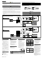
Receiving 4-20 mA DC Current
Signals with the Manual Setter
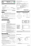
■ Model UD310-00 Terminal Arrangement
NOTE
Do not use unassigned terminals as relay terminals.
11
ALM2
12
ALM1
13
Universal input-selectable
input type
Measured Value (PV) Input
Alarm Outputs
RTD Input
TC Input
+
7
COM
8
–
6
B
7
b
8
A
* When receiving 4-20 mA DC current signals,
set the PV input type to 1-5 V DC (setpoint “22”).
DC mV or V Input
7
+
8
–
7 +
250 Ω 4-20mA
8
PV Retransmission Output
1
+
2
–
4 to 20 mA DC
Note: Connecting a 250 Ω resistor to the terminals is
optional.
Model: X010-250-2 (resistor with M3.5 crimp-on terminal
lugs)
6
1
11
2
12
7
3
13
8
4
14
9
5
15
10
-
Power Supply
CAUTION
L
9
+
9
AC/DC 24V
10
10 –
N
100-240V AC
when /V24 option is specifed.
To prevent damage to the manual setter,
never provide 100-240V AC power supply
for power supply AC/DC 24V model (when
⬙/V24⬙ is specified).
NOTE
Manual Setting (SP) Output
The + and – stand for the polarity
for DC 24V power supply.
4 to 20 mA Output
+
14
15 –
■ Models UD320-00/UD350-00 Terminal Arrangement
Measured Value (PV) Input
Note:The terminal arrangements of the UD320 and UD350 are the same.
RTD Input
TC Input
12
Receiving 4-20 mA DC Current
Signals with the Manual Setter
Universal input-selectable
input type
* When receiving 4-20 mA DC current signals,
11 B
+
set the PV input type to 1-5 V DC (setpoint “22”).
DC mV or V Input
12
+
12 +
12 b
13
NOTE
–
250 Ω 4-20mA
13 –
13 A
13 -
Do not use unassigned terminals as relay terminals.
11
12
4 to 20 mA Output
13
14
14
PV Retransmission Output
29
+
4 to 20 mA DC
30 –
16
27
17
28
18
29
19
30
20
+
Alarm Outputs
15 –
15
26
Note: Connecting a 250 Ω resistor to the terminals is
optional.
Model: X010-250-2 (resistor with M3.5 crimp-on terminal
lugs)
Manual Setting (SP) Output
16
ALM2
17
ALM1
18
COM
CAUTION
To prevent damage to the manual setter,
never provide 100-240V AC power supply
for power supply AC/DC 24V model (when
⬙/V24⬙ is specified).
Power Supply
19
L
19
+
NOTE
AC/DC 24V
20
20 –
N
100-240V AC
when /V24 option is specifed.
The + and – stand for the polarity
for DC 24V power supply.
6. Hardware Specifications
Measured Value (PV) Input
1 point
• Input:
type: Universal; can be selected by software
• Input
accuracy (at 23 ±2°C ambient temperature)
• Input
Thermocouple: ±2°C ±1digit
•
•
•
•
•
•
•
•
•
•
However,
• ±4°C for thermocouple input –200 to –100°C
• ±3°C for thermocouple input –100 to 0°C
• ±5°C for types R and S (±9°C for 0 to 500°C)
• ±9°C for type B (accuracy is not guaranteed for 0 to 400°C)
• RTD: ±1°C ±1digit
•Voltage(mV, V) : ±0.3% ±1digit
Sampling period for measured value input: 500ms
Burn-out detection: Functions for thermocouple or RTD input
(burn-out upscale only; cannot be switched off)
Input resistance: 1MΩ or greater for thermocouple
or DC mV input. Approx. 1MΩ for DC V input
Maximum allowable signal source resistance :
250Ω for thermocouple or DC mV input
2kΩ for DC V input
Maximum allowable wiring resistance for RTD input:
10Ω/wire (The resistance values of three wires must be the same.)
Allowable input voltage: ±10V DC for thermocouple or DC mV input
±20V DC for DC V input
Noise rejection ratio: Normal mode noise: Min. 40dB
(50/60Hz)
Common mode noise: Min. 120dB
(Min. 90dB for DC V input)
Error of reference junction compensation:±1.5°C (at 15-35°C)
±2.0°C (at 0-50°C)
The reference junction compensation cannot be switched off.
Applicable standards:
Thermocouple and resistance temperature detector(RTD)
JIS/IEC/DIN (ITS90)
Alarm types: 22 types
• (waiting
action can be set by software):
•
Retransmission Output
signal: Measured value in 4-20mA DC,
• Output
can be scaled.
load resistance: 600Ω
• Maximum
Output accuracy: ±0.3% of span
• (at
23±2°C ambient temperature)
Manual Setting (SP) Output
•
•
IM05F01F12-01E
Power Supply and Isolation
Compliant with IEC/EN61010-1: 2001,
• Safety:
approved by CSA1010, approved by UL508.
PV high limit, PV low limit, Deviation high
limit, Deviation low limit, De-energized on
deviation high limit, De-energized on deviation
low limit, Deviation high and low limits,
Deviation within high and low limits, Deenergized on PV high limit, De-energized on
PV low limit, Fault diagnosis output, FAIL
output
Alarm output: 2 relay contacts
Relay contact capacity: 1A at 240V AC or 1A
at 30V DC (with resistance load)
(COM terminal is common)
Note: The alarm output relays cannot be replaced by users.
•
Installation category : CAT. II (IEC/EN61010,
CSA1010) Pollution degree : 2
(IEC/EN61010, CSA1010)
Measurement category : I
(CAT. I : IEC/EN61010)
Rated measurement input voltage : 10V DC
max.(across terminals), 300V AC max.(across
ground)
Rated transient overvoltage : 1500V (Note)
Note : It is a value on the safety standard
which is assumed by IEC/EN61010-1 in
measurement category I, and is not the value
which guarantees an apparatus performance.
Caution: This equipment has Measurement
category I, therefore do not use the equipment
for measurements within measurement
categories II, III and IV.
EMC standards: Complies with EN61326.
The instrument continues to operate at a
measuring accuracy of within ±20% of the
range during tests.
Internal Wiring
3
Entrance 4
Cable
Measurement category
SP (target setpoint) will be output in 3 seconds
after the change.
Output: 1 point
Output type: Current output
Output signal: 4 to 20mA current output
Maximum load resistance: 600Ω
Output accuracy: ±0.3% of span
(at 23±2°C ambient temperature)
Safety and EMC Standards
Alarm Functions
■ Alarm Functions
Description
2
T
Remarks
1
CAT.1
For measurements performed on circuits not directly connected to MAINS.
2
CAT.2
For measurements performed on circuits directly connected to the low voltage installation. Appliances, portable equipments, etc.
3
CAT.3
For measurements performed in the building installation.
Distribution board, circuit breaker, etc.
4
CAT.4
For measurements performed at the source of the low-voltage installation.
Overhead wire, cable systems, etc.
2
■Power Supply
Power
supply
Rated at 100-240VAC (±10%)
AC/DC 24V, 20 to 29V of
allowable range when
⬙/V24⬙ is specified.
50 or 60Hz
Voltage
Frequency
Maximum power consumption
Memory
Withstanding Between primary terminals
and secondary terminals
voltage
(See Notes 1 and 2.)
Insulation Between primary terminals
resistance and secondary terminals
(See Notes 1 and 2.)
8VA max. (4W max.)
3W max. when
⬙/V24⬙ is specified.
Non-volatile memory
1500V AC
for 1 minute
■ Isolation
The bold lines below indicate reinforced isolation, and
the broken line indicates functional isolation.
Power supply
Power supply
terminals AC/DC 24V
terminals
(When ⬙/V24⬙ is specified)
(100-240V AC)
Measured value input
terminals
Internal circuit
Alarm output
Manual setting output
terminals
terminals : 4-20 mA
(2 relay contacts)
Retransmission output
terminals : 4-20 mA
Note: The measured value input terminals is isolated from the
internal circuit.
•
•
•
•
•
•
•
•
•
•
•
IP55 [Models UD320 and UD350].
For side-by-side close installation the controller
loses its dust-proof and drip-proof protection.
Casing: ABS resin and polycarbonate
Case color: Black
Weight: UD310 - approx. 200g
UD320 - approx. 300g
UD350 - approx. 400g
Mounting: Flush panel mounting
Wiring: Screw terminals
Environmental Conditions
20MΩ or more at
500V DC
Note 1: The primary terminals are the power supply terminals and
alarm output terminals.
The secondary terminals are the analog input and output terminals.
Note 2: AC/DC 24V terminals are secondary terminals.
•
Construction, Mounting, and Wiring
Construction: Dust-proof and drip-proof front
• panel
conforming to IP65 [Model UD310] and
■Normal Operating Conditions
time: At least 30 minutes
• Warm-up
Ambient temperature:0-50°C (0-40°C when
• mounted
side-by-side)
of change of temperature: 10°C/h or less
• Rate
humidity: 20-90% RH (no condensation allowed)
• Ambient
field: 400A/m or less
• Magnetic
vibrations of 5 to 14Hz: Amplitude of 1.2mm or less
• Continuous
Continuous
vibrations
14 to 150Hz: 4.9m/s (0.5G) or less
• Short-period vibrations:of14.7m/s
for 15 seconds or less
• Shock: 98m/s (10G) for 11(1.5G)
milliseconds or less
• Mounting angle: Upward incline
up to 30
• degrees; downward incline is not ofallowed.
Altitude: 2000m or less above sea level
•■Maximum
Effects from Operating Conditions
2
2
2
(1) Temperature effects
Thermocouple, DC mV and DC V input: ±2µV/°C
or ±0.02% of F.S./°C, whichever is larger
Resistance temperature detector: ±0.05°C/°C
Analog output: ±0.05% of F.S./°C
(2) Effect from fluctuation of power supply voltage
(within rated voltage range)
Analog input: ±0.2µV/V or ±0.002% of F.S./V,
whichever is larger
Analog output: ±0.05% of F.S. /V
•
•
•
•
•■Transportation and Storage Conditions
–25 to 70°C
• Temperature:
5 to 95% RH (no condensation allowed)
• Humidity:
Shock: Package drop height 90cm (when packed in
• the
dedicated package)