1
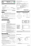
7. Key Operations
IMPORTANT
CAUTION
The manual setter is shipped with the parameters set at the factory-set defaults. Check the default values against
the “Parameter Lists” in the following page, and change the parameter setpoints that need to be changed.
To prevent electric shock, the manual setter should be mounted on the panel so as not to accidentally touch the
terminals when power is being applied.
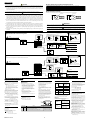
(1) You can move between parameter setting displays using the
(2) To change the parameter setpoint,
( i ) Change the display value with the
(ii) Press the
or
This section explains how to set and register parameter setpoints.
The procedure for changing Target Setpoint(SP) and Alarm 1 Setpoint(A1) can be found on "Changing Target
Setpoint(SP)" and "Changing Alarm 1 Setpoint(A1)".
You can set the other parameters in the same way.
key.
key (the period flashes).
■ Changing Target Setpoint (SP)
key to register the setpoint.
(3) In the operating display, pressing the
Check alarm type before setting the alarm setpoint.
Factory-set settings:
Alarm 1 type : OFF
Alarm 2 type : OFF
The following instructions assume that the manual
setter is already receiving power.
SP (target setpoint) value will be output in 3
seconds after the change.
key for at least 3 seconds retrieves the operating parameter setting display.
(4) In the operating parameter setting display, pressing the
■ Changing Alarm 1 Setpoint (A1)
key for at least 3 seconds transfers back to the oper-
ating display.
Registering the key-lock parameter LOC to “–1” retrieves the setup parameter setting display.
(5) In the setup parameter setting display, pressing the
Step 1:
Confirm that the manual setter
shows the operating display
during normal operation (PV
and SP are displayed on the
indicators).
key for at least 3 seconds transfers back to the operating display.
NOTE
Changing certain setup parameters may automatically initialize the operating parameters. Therefore, after you
change the setup parameters, always check the operating parameter setpoints to find out if appropriate values have
been set for them. If the operating parameters have been initialized, set them to their appropriate values.
NOTE
then press the
UD310
UD310
Step 2:
To enter the operating parameter
setting display, press the
key
for at least 3 seconds.
Step 2:
Press the
or
key to
change the SP display value to
the required setpoint. In this
example, SP is changed to
200°C.
At power-on, the manual setter displays the operating display, but if the measured input type setting remains
OFF, “IN” appears. In this case, press the
key to display the measured input range code you want to use,
Step 1:
Confirm that the manual setter
shows the operating display
during normal operation (PV
and SP are displayed on the
indicators).
UD310
UD310
key to register it. (Refer to the flowchart below.)
Press for at least 3 seconds.
Power ON
A
Step 3:
Press the
or
key to
change the current A1 setpoint
to a required setpoint. In this
example, A1 is changed to
200°C.
NOTE
At first
When measured input range code has been already set,
the operating display shown below appears.
No
Yes
is displayed
?
Operating Display
Minimum value
of measured input
range (scale)
UD310
Maximum value
of measured input
range (scale)
The period flashes while the setpoint is being changed.
Measured input range
Measured input
value(PV)
TIP
Set the parameters
as follows not to
display a measured
input value.
No display
Target setpoint(SP)
Measured input type (IN):
DC voltage input (20 to 23)
Target setpoint(SP)
UD310
UD310
When parameter PVD=ON
(factory-set default)
PV/SP display (PVD)
: OFF
When parameter PVD=OFF
When “In” appears, press the
key to display the measured input
range code you want to use, then
press the
key to register it.
After this operation, the manual
setter shows the operating
display.
SPL
SPH
Target setpoint range
(after scaling)
20mA
4mA
Note
Press the
key for
at least 3 seconds.
(To operating
display)
Press the
key
for at least
3 seconds.
SPH
SPL
Target setpoint range
(Factory-shipped settings)
Manual setting output
(4 to 20mA)
A
Press the
key for
at least 3 seconds.
(To operating
display)
Note
Step 4:
Press the
key once to
register the setpoint.
The period goes out.
A1 is now changed.
Another press of the
key calls up the Alarm 2
setpoint(A2) display.
To return to the operating
display, press the
Note: If no key is pressed for a period
of two minutes or more while in
the operating or setup parameter
setting display, the manual setter
automatically returns to operating
display.
UD310
UD310
The period goes out.
key for at least 3 seconds.
8. Troubleshooting
In the event of an abnormality, perform the following checks as outlined by the flowchart.
Is the manual setter defective?
Yes
Operating Parameter Setting Display
Setup Parameter Setting Display
No
Completely inactive?
Press the
key
IN
to move
between items.
A1
A2
FL
BS
LOC
LOC=
• Displayed when AL1, AL2 = 1 to 20
When LOC=–1,
transfers to the
setup parameter
setting display
Press the
key
to move
between items.
Yes
DP
RH
RL
Check the terminal connection
of the power supply
Displayed when DC voltage
input range code (20 to 23)
is set
NOTE
Set ⬙-1⬙ to enter the setup parameter setting
display. But if ⬙LOC=1 or 2⬙ is already set, the
parameter value can not be changed by setting
⬙LOC=-1⬙ only. To change the parameter value,
set ⬙LOC=0⬙ at first (for disabling keylock),
then set ⬙LOC=-1⬙ once again.
No
Yes
Turn the power off,
then on
Check the power
supply voltage
SPH
SPL
No
I/O signal failure?
No
Yes
Verify the I/O spec.
of manual setter
Verify the spec. of
I/O destinations
No
Normal?
No
Correct it
No
AL1
AL2
HY1
HY2
Display failure?
Yes
Check key-lock
setting
RTH
RTL
When
–1
Key operation failure?
Is the key
locked?
Yes
Normal?
Yes
Yes
Contact us for repair
Cancel the setting
Problem solved
■ Error Display during Operation
PVD
(1) If the manual setter displays one of the following, carry out the appropriate remedy for the particular error.
Display
Error content
P.Er
● UD310/UD320/UD350 Measured Input Type and Ranges
Input type
Unspecifed
–270 to 1370 °C
0.0 to 600.0 °C
0.0 to 400.0 °C
–199.9 to 200.0 °C
J
–199.9 to 999.9 °C
T
–199.9 to 400.0 °C
E
–199.9 to 999.9 °C
R
0 to 1700 °C
S
0 to 1700 °C
B
0 to 1800 °C
N
–200 to 1300 °C
L
–199.9 to 900.0 °C
U
–199.9 to 400.0 °C
Platinel 2
0 to 1390 °C
–199.9 to 850.0 °C
0.0 to 400.0 °C
Pt100
–199.9 to 200.0 °C
–19.9 to 99.9 °C
JPt100
–199.9 to 500.0 °C
0 to 100mV 0.0 to 100.0
0 to 5V 0.000 to 5.000
User-scalable
1 to 5V 1.000 to 5.000
0 to 10V 0.00 to 10.00
RTD
Thermocouple
K
DC voltage
Range (°C)
Range code (°C)
OFF
1
2
3
4
5
6
7
8
9
10
11
12
13
14
15
16
17
18
19
20
21
22
23
Range (°F)
Range code (°F)
– 300 to 2500°F
32.0 to 999.9°F
32.0 to 750.0°F
– 300 to 400°F
– 300 to 2100°F
– 300 to 750°F
– 300 to 1800°F
32 to 3100°F
32 to 3100°F
32 to 3200°F
– 300 to 2400°F
– 300 to 1600°F
– 300 to 750°F
32 to 2500°F
– 199.9 to 999.9°F
32.0 to 750.0°F
– 300 to 400°F
– 199.9 to 999.9°F
31
32
33
34
35
36
37
38
39
40
41
42
43
44
45
46
47
48
B.o
OOO
UUU
No PV display
The parameter is abnormal
Input burnout
Remedy
Check the setpoints of all the parameters and set them
at their proper values.
Check the sensor wiring and correct it.
Not display when the setup parameter PVD=OFF.
PV over-scale
(PV exceeds its effective range.) Check the measured input type and scale settings and
correct them.
PV under-scale
Not display when the setup parameter PVD=OFF.
(PV falls below its effective range.)
Set the setup parameter PVD=ON to display PV.
(2) The manual setter needs to be repaired if any of the indications in the table below appear.
In these cases, do not try to repair the manual setter yourself.
Order a new manual setter or contact us for repair.
Display
Unknown (at power-on)
All extinguished (at power-on)
“Err” (at power-on)
UD310
Error content
CPU failure
Power source failure
Calibration abnormal
Display
Error content
Flashing “Err” (at power-on) RAM or ROM failure
A/D converter failure,
Flashing “Err”
RJC failure, or EEPROM failure
(during operation)
■ When Power Failure Occurred during Operation
● Momentary power failures shorter than 20ms(or shorter than 1ms when ⬙/V24⬙ is specified) have no effect on
the manual setter operation (i.e., normal operation continues).
● For power failures of 20ms or longer(or 1ms or longer when ⬙/V24⬙ is specified), however the status will be
as follows.
(The manual setter action at power recovery is the same as at power-on.)
• Alarm action: Continues (but alarms with a waiting action enter the waiting state once)
• Setting parameters: Maintained
For example, to select
thermocouple type J (°F),
set the range code to 35.
3
IM05F01F12-01E