1
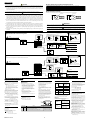
Description of Measured Input
■ Parameter Lists
(1) Operating Parameters : Parameters changed rather frequently during operation.
Code
Alarm 1
setpoint
A1
Alarm 2
setpoint
A2
PV input
filter
FL
Setting range and unit
Name
Default
■ PV alarm Unit: °C/°F
Setting range: [minimum value - (maximum value minimum value)] to maximum value of measured
input range (scale)
■ Deviation alarm Unit: °C/°F
Setting range: –100 to 100% of the measured input
range (scale) span
Example of Temperature Input
-270°C
Minimum value
of measured
input range
Depends on the
alarm 1 type.
2-seconds filter
Measured Input Range
1370°C
Maximum value
of measured
input range
1V
1370°C
RL
5V (input signal)
Measured Input Range
Measured Input Scale
Display Scale
Depends on the
alarm 2 type.
-270°C
OFF, 1 to 120 seconds
This function should be used when the PV display
value may fluctuate greatly, for example, when the
measured input signal contains noise. The filter is of
the first-order lag type, and FL sets the time constant.
If a larger time constant is set, the filter can remove OFF
more noise.
Input
Example of Voltage Input
User setting
RH
Maximum value
of measured input
scale (RH)
200.0°C
Minimum value
of measured input
scale (RL)
0.0°C
Parameters to be set for temperature input.
1. Measured input type (IN) : Set according to a sensor.
Parameters to be set for voltage input.
1. Measured input type (IN) : Set according to an input signal.
2. Decimal point position of measured input (DP) :
Set the position of the decimal point for measured input display.
3. Maximum value of measured input scale (RH) :
Set the maximum value of the scale.
(Set the display value at maximum value of input signal.)
4. Minimum value of measured input scale (RL) :
Set the minimum value of the scale.
(Set the display value at miminum value of input signal.)
Note : Display scale can not be changed.
10-seconds filter
–100 to 100% of measured input range (scale) span
This function adds a bias value to the measured input value,
and the result is used for display and retransmission output.
PV input
bias
BS
PV value inside the manual setter
= measured input value + PV input bias
Description of Alarm Functions
0% of measured
input range
(scale) span
■ Alarm Function List
This function is useful for carrying out fine adjustment when
the PV value is within the required accuracy but it differs from
the value obtained by other equipment.
Key lock
LOC
0: No key lock
1: Prevents parameter from being changed of except
for SP in the operating display.
2: Prevents all parameter changing operations
including SP in the operating display.
–1: Set ⬙-1⬙ to enter the setup parameter setting
display.
But if ⬙LOC=1 or 2⬙ is already set, the parameter
value can not be changed by setting ⬙LOC=-1⬙ only.
To change the parameter value, set ⬙LOC=0⬙ at first
(for disabling keylock), then set ⬙LOC=-1⬙ once
again.
Alarm
type code
Action
Alarm type
“Opn” and “Cls” indicate that the relay contact is
opened and closed; “(on)” and “(off)” indicate that
the lamp is on and off; and white triangles indicate
temperature setpoints.
Closed contact Open contact
during alarm during alarm
No alarm
OFF
Hysteresis
PV
high limit
0
Cls (on)
Cls (on)
2
Deviation
high and low
limit
Opn (off)
Alarm setting
6
Opn (on)
12
(See note.)
Measured value
Name
Default
Measured
input type
1 to 23, 31 to 48 (See input range code list.)
OFF: No input
(If no input type is specified at the time of ordering, you must set the
input type.)
Decimal
point
position of
measured
input
0: No decimal place (nnnn)
1: One decimal place (nnn.n)
2: Two decimal places (nn.nn)
3: Three decimal places (n.nnn)
IN
DP
Setting range and unit
RH
Maximum
value of
measured
input scale
RL
Minimum
value of
measured
input scale
3
Deviation
high limit
OFF, or the input
range code
specified with
order
Opn
(off)
Deviation
low limit
Cls (on)
Measured value
Temperature setpoint
14
(See note.)
Hysteresis
100.0
De-energized
on deviation
high limit
(Displayed at voltage input)
Cls (off)
15
(See note.)
De-energized
on PV
low limit
Fault
diagnosis
alarm
10
Cls (off)
Alarm setting
20
(See note.)
Measured value
The output contact is opened in the following events:
The contact is closed at input
burnout.
FAIL
output
21
• Program error
• ROM error
• RAM error
• power failure
°C
Note: The alarms numbered 1 to 10 have no waiting
action, while alarms 11 to 20 have a waiting
action.
The waiting action turns off the PV and deviation
alarms that occur from the start of the control
operation until a stable state is reached.
Maximum value
of measured input
range (scale)
19
(See note.)
Alarm setting
Opn (on)
Temperature setpoint
0.0
Opn (on)
Hysteresis
5
Deviation setting
18
(See note.)
9
Cls
(off)
Measured value
Opn (on)
Measured value
8
Opn (off)
Measured value
Deviation setting
Temperature setpoint
De-energized
on PV
high limit
Opn (off)
Deviation setting
(Displayed at voltage input)
Maximum
value of target SPL setting range:
setpoint range Minimum value of the measured input range (scale) to
(SPH –1digit) ; Unit: °C/°F
(Setpoint for
Minimum value
Maximum value
manual setting
of measured input
of measured input
range (scale)
range (scale)
output 20mA)
Opn (off)
17
(See note.)
Hysteresis
4
1
–1999 to (RH –1)
Measured value
Temperature setpoint
Hysteresis
Hysteresis
Cls (on)
Hysteresis
(Displayed at voltage input)
(RL + 1) to 9999
13
(See note.)
Cls
(on)
Deviation setting
Deviation
within highand -lowlimit
Cls (on)
Deviation setting
Measured value
Temperature setpoint
SPH setting range:
(SPL+1digit) to the maximum value of the measured
input range (scale) ; Unit: °C/°F
SPH
Opn (off)
Hysteresis
7
Cls
(on)
Hysteresis
User setting
16
(See note.)
Deviation setting
Measured value
Temperature setpoint
(2) Setup Parameters : Parameters rarely changed in normal use after once having been set.
Code
Cls (off)
Hysteresis
Hysteresis
PV
low limit
De-energized
on deviation
low limit
11
(See note.)
Measured value Alarm setting
Closed contact Open contact
during alarm during alarm
Hysteresis
1
Opn (off)
Alarm
type code
Action
“Opn” and “Cls” indicate that the relay contact is
opened and closed; “(on)” and “(off)” indicate that
the lamp is on and off; and white triangles indicate
temperature setpoints.
Alarm type
Normal
Taken as
normal.
Waiting action
• A/D converter error
• RJC error
• EEPROM error
22
Abnormal
Alarm output = ON
Low limit alarm
setpoint
In this area, the alarm output is turned
off even when a measured value falls
below the low limit alarm setpoint.
Measured input range
Time
Power-on
SPH
SPL
SPL
Minimum
value of target
setpoint range
Target setpoint range
(Factory-set default)
(Setpoint for
manual setting
output 4mA)
Target setpoint range
(after scaling)
SPL
SPH
4mA
20mA
Minimum value
of measured input
range (scale)
Description of Alarm hysteresis
The alarms are output as relay outputs. Since a relay has a limited service life, excessive on/off actions will
shorten the life of the relay. To prevent this, you can set a hysteresis for both alarm 1 and alarm 2 to moderate
excessive on/off actions.
Manual setting output
(4 to 20mA)
Temperature input : Within measured input range
RTH
Voltage input : (RTL+1digit) to max. value of measured
Maximum
input scale(RH)
Maximum value of
value of
Min. value of measured input scale(RL) to (RTH-1digit) measured input
retransmission However, RTL<RTH
range (scale)
output
Minimum value
of measured input
range (scale)
< PV High Limit Alarm >
Relay contact is closed (ON)
Maximum value
of measured input
range (scale)
Relay contact
is opened
Measured input range
Temperature
Relay contact is closed (ON)
Relay contact
is opened
Alarm 1 setpoint : 100°C
RTH
RTL
HY1 : 15°C
HY1 : 5°C
Temperature
Alarm 1 setpoint : 100°C
Retransmission range
(Factory-set default)
RTL
Minimum
value of
retransmission
output
RTL
RTH
Retransmission range
(after scaling)
4mA
Minimum value of
measured input
range (scale)
Measured input
value (PV)
Alarm ON
Measured input
valued (PV)
20mA
OFF
Retransmission output
(4 to 20mA)
ON
Alarm 1 type
AL1
Alarm ON
OFF
OFF
OFF or a value from 1 to 22 (see the table of alarm
function list), and either
ON
Alarm 2 type
OFF
Alarm 1
hysteresis
0.5% of measured
input range
(scale) span
AL2
HY1
HY2
0.0 to 100.0% of measured input range (scale) span
Unit: °C/°F
Alarm 2
hysteresis
OFF
OFF
time
0.5% of measured
input range
(scale) span
ON: Displays PV (measured input) and SP (target setpoint)
OFF: Displays SP (target setpoint)
Measured input(PV)
PV/SP
display
Factory-shipped setting
(PVD=ON)
Target setpoint(SP)
UD310
ON
No display
PVD
(PVD=OFF)
Even if a measured input
(PV) is not displayed,
the PV retransmission
ouptut and the alarm
action work normally.
IM05F01F12-01E
Target setpoint(SP)
UD310
4
time