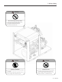
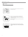
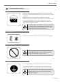
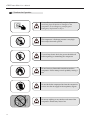
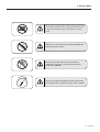
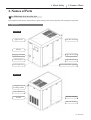
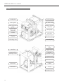
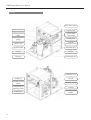
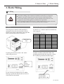
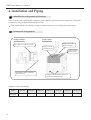
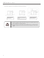
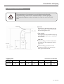
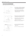
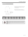
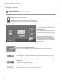
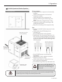
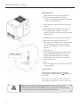
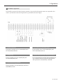
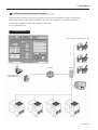
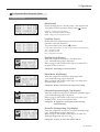
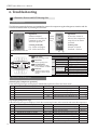
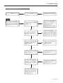
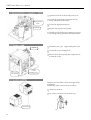
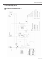
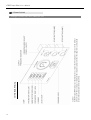
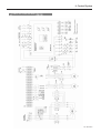
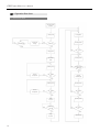
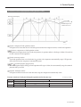
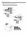
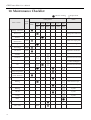
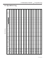
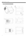
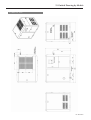
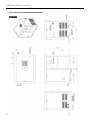
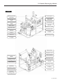
1
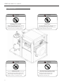
User’s Manual of Compressor
DANGER
Be sure to check airend rotating direction
when operating the compressor for the
first time after installation.
If it rotates in the opposite direction, the
airend can be damaged.
Be sure to check the
rotating direction !
The user s manual is prepared, based on GRH3-100A.
Read this manual carefully before installing and operating the compressor
and use it properly.
In addition, after reading this manual, keep it close to the compressor for
future reference such as repair, maintenance or trouble.
GRH3 star-delta User’s Manual
Preface
Thank you for purchasing Hanshin Compressor. Hanshin Screw Compressor is the product
developed by our long history, abundant experience and accumulated technology.
The screw compressor has been verified for the performance by examined design and
appropriate reliability test and is conveniently programmed to be optimally operated when the
control-related data are automatically calculated and changed if a user simply changes the
operation pressure by Micom s control almost close to AI.
The function guarantees that the compressor operates optimally, so the company assures of high
performance, highly evaluated from users.
Every machine and controller may show 100% of the performance as long as it is
clearlyunderstood and well maintained. Please read this manual carefully before use.
3
GRH3 star-delta User’s Manual
Contents
About how to use the manual
5
1. About Safety
1-1
1-2
1-3
1-4
1-5
1-6
1-7
1-8
1-9
General Cautions
About Marks and Symbols
Check Caution/Warning Label
Safety Rules
Installation Place and Cautions for Installation
Cautions for Electric Wiring
Cautions for Operation
Cautions for Stoppage
Cautions for Maintenance
6
6
7
11
13
14
15
17
17
2. Names of Parts
2-1
2-2
GRH3-20A, 25A, 30A, 35A, 50A
GRH3-75A, 100A
18
20
3. Electric Wiring
3-1
3-2
Wiring
Power Facilities
22
24
4. Installation and Piping
4-1
4-2
4-3
4-4
Identification of the product specifications
Cautions for Transportation
Cautions for Installation
Cautions for Piping
25
25
26
30
5. Operations
5-1
5-2
5-3
5-4
5-5
5-6
5-7
5-8
5-9
Micom Controller
Operation Control
Initial Operation & Routine Operation
Schedule Operation
Remote operation
Remote Monitoring System[Micom]
Remote Monitoring System[Computer]
Micom Display Configuration & Operations
Operation Data Setup and Check
33
35
36
39
40
41
42
43
44
6. Troubleshooting
6-1
6-2
Protective Devices and LCD Message List
Trouble Causes and Measures
51
52
7. Maintenance
7-1
7-2
Regular Maintenance
Maintenance Method
57
58
8. Control System
8-1
8-2
8-3
8-4
Compressor Configuration Layout
Control Circuit
Operation Flow Chart
Arrangement Diagram and Spec. of Control Parts
60
61
65
67
9. Specifications
70
10. Maintenance Checklist
71
11. Operation Log
72
12. Quality Warranty
73
13. Outside Drawing by Models
74
4 / Hanshin
GRH3 star-delta User’s Manual
About how to use the manual
The screw compressor is intended to be used domestically (the Republic of Korea).
The manual describes the routine operation, repair and maintenance of the manual as well as the
installation, general management and periodic maintenance of it.
Before installing the compressor, carefully read this manual, fully understand it and follow the description.
Also, keep this manual handy for future reference.
If you find any doubtful content in the manual, please contact your dealer or the company s A/S service
center(TEL.031-494-8484).
Warning
Do not directly inhale compressor air nor use it for machines designed for the
respiratory organs.
Direct inhalation may cause dangerous unexpected accidents such as dyspne
Type Explanation
GRH3 - 100 A
Output (HP)
Air cooling : A / Water cooling type : W
The informative plate as model, serial number, operation pressure and voltage is attached on the left side of
the compressor. Please fill it for your regular maintenance and parts order.
MODEL
SERIAL NO
WORK PRESSURE
VOLTAGE
MANUFACTURING
5
About how to use the manual
1. About Safety
1. About Safety
For the safety purpose, read the cautions and warnings specified in the manual carefully and fully
understand them for proper use. The chapter especially highlights the safety items.
1-1 General Cautions
The installation, operation, preservation, repair and other works of the product should be executed by a
competent engineer.
If a user adds a control circuit to the product or attempt to modify or alter the product without permission,
it may cause physical injuries or damages on the product due to the malfunction of the protective devices,
which may not be covered by the warranty. At the moment, the product may be repaired by our pay
service.
Do not use the compressed air of the compressor for direct inhalation or air supply source of the
respiratory organs. It may cause dangerously physical injuries.
[Warning] or [Caution] in the manual contains important information that should be always followed.
1-2 About Marks and Symbols
The important items to be noted for the safe use and trouble avoidance are marked as below, so every
operator should understand and keep them.
Marks
Warning
Warning
The mark is displayed when there is any possibility of death, serious injuries or
other dangerous situation unless the product is handled properly.
Caution
Caution
The mark is displayed when there is any possibilityof slight injuries, dangerous
situations and damages on properties unless the product is handled properly.
Prohibition
It means prohibited operation or handling.
The prohibition is displayed as characters in the mark.
6 / Hanshin
GRH3 star-delta User’s Manual
1-3 Check Caution/Warning Label
1. GRH3-20A, 25A, 30A, 35A, 50A
Caution
Discharge pressure ejection
When checking/replacing parts, the compressor
should stop with the pressure set to 0
A special attention should be paid around a safe
valve because it may work during operation.
Caution
Beware of a scald
Oil cooler, air end and tank may be very hot during
or just after operation, probably causing a scald.
When working around any heating source, you
should wait until it is cooled after turn-off
7
Caution
Electric shock
The power should be off before checking the electric
box because of the danger of electric shock.
After turning it off, a sign, “Power-off for check”
should be indicated to avoid accident.
Warning
Be careful of being rolled by rotation
Do not touch yourself or other articles on any
rotating parts such as main/fan motor.
The power should be off before repair,
maintenance and other works
1. About Safety
Warning
Be careful of being rolled by rotation
Do not touch yourself or other articles on any
rotating parts such as main/fan motor.
The power should be off before repair,
maintenance and other works
Caution
Cautious of Inhalation
Poorly-ventilated indoor operation may cause death
or accident.
Do not directly inhale the compressed air nor use
it for air supply of the respiratory organs.
Caution
Beware of a scald
Oil cooler, air end and tank may be very hot during
or just after operation, probably causing a scald.
When working around any heating source, you
should wait until it is cooled after turn-off
8 / Hanshin
GRH3 star-delta User’s Manual
2. GRH3-75A, 100A
Caution
Discharge pressure ejection
When checking/replacing parts, the compressor
should stop with the pressure set to 0
A special attention should be paid around a safe
valve because it may work during operation.
Caution
Beware of a scald
Oil cooler, air end and tank may be very hot during
or just after operation, probably causing a scald.
When working around any heating source, you
should wait until it is cooled after turn-off
9
Caution
Electric shock
The power should be off before checking the electric
box because of the danger of electric shock.
After turning it off, a sign, “Power-off for check”
should be indicated to avoid accident.
Warning
Be careful of being rolled by rotation
Do not touch yourself or other articles on any
rotating parts such as main/fan motor.
The power should be off before repair,
maintenance and other works
1. About Safety
Warning
Be careful of being rolled by rotation
Do not touch yourself or other articles on any
rotating parts such as main/fan motor.
The power should be off before repair,
maintenance and other works
Caution
Cautious of Inhalation
Poorly-ventilated indoor operation may cause death
or accident.
Do not directly inhale the compressed air nor use
it for air supply of the respiratory organs.
Caution
Beware of a scald
Oil cooler, air end and tank may be very hot during
or just after operation, probably causing a scald.
When working around any heating source, you
should wait until it is cooled after turn-off
10 / Hanshin
GRH3 star-delta User’s Manual
1-4 Safety Rules
Common rules
Before operating, maintaining or repairing the compressor, fully
understand the manual.
Make sure to wear proper safety devices and uniform when
repairing or maintaining the compressor. Especially, when
assembling or disassembling a heavy article, you should put on
helmet and safety boots.
Since a very hot air may be emitted, you should wear protective
uniform or goggles.
Setting or re-setting the values of the compressor should be
executed by an expert. If it is not possible, an engineer(worker)
should follow the directions from an expert or an experienced
engineer.
11
1. About Safety
Transportaion
Using a forklift
When transporting the product, it needs covering with a cloth to
avoid scratch or transformation.
A forklift used to transport it should be a suitable type to avoid
overturn and other accidents.
Using a crane
When transporting the compressor using a crane, check the load
and slowly moveit by using a rope or a crane.
Thecompressor should be covered with a cloth or shock-absorbing
materials to protect against the rope on the top.
Warning
Warning
When moving it using a crane, move it slowly while
leveling. Unbalanced transportation may cause a fall,
probablyleading to a loss of lives.
No one is allowed to be under the compressor while it
is being moved. It may cause a loss of lives.
12 / Hanshin
GRH3 star-delta User’s Manual
1-5 Installation Place and Cautions for Installation
Place
The compressor is designed to use indoors. Please avoid installing it outside.
Caution
Installing in a place directly exposed to raindrops or
underground with hot ambient temperature may
cause electric shock, drain or rust.
Caution
Installing the compressor in a place with vibration
may cause bad contact, destruction of air end and
piping, so a measure should be taken before the
installation
Caution
If the compressor is installed in a place with harmful
gas, it may cause oxidization of lubricant and
corrosion parts.
Caution
Do not leave any flammable materials around the
compressor. Any work causing a fire is also
prohibited. Once a flame is moved into the
compressor, it may cause damages.
Caution
Do not install the compressor in a place with 40°…and
higher ambient temperature. It may cause a fire or
damages on the compressor.
Caution
When installing it in an airtight space, it needs
induction and ventilation pipes. And the vent needs a
fan to ventilate the space.
Installation
Air-tight space
13
1. About Safety
1-6 Cautions for Electric Wiring
Wiring
Wiring should be executed in accordance with the indoor wiring
rules of the common industrial technology standard, electric facility
standards.
Wiring should be executed only by a competent electrician.
When wiring on the terminals of the compressor, it should be wired
to avoid any bending part while a hole into which wires are
penetrated should be protected for the sheath from vibration by
using rubber and other materials.
Caution
Since electric leakage, weak insulation, overcurrent, ground fault,
open-phase operation or defect of protective devices may cause a
fire on electric circuits, it should be wired in accordance with the
indoor wiring rules and periodically maintained.
Circuit Breaker
Install a circuit breaker suitable for the type on the power lead-in.
Protective Devices
Caution
Removing and improving the compressor protective devices or
changing the settings may cause an accident. Never attempt to
change or alter the settings of protective devices.
Grounding
Connect the grounding to the grounding terminal inside the electric box.
The grounding should be type 3 grounding if the voltage is lower than
AC400V or special type 3 grounding if the voltage is AC400V and higher.
Caution
Without grounding, it may cause an electric shock accident or
failure of the compressor.
14 / Hanshin
GRH3 star-delta User’s Manual
1-7 Cautions for Operation
Caution
Caution
Caution
Caution
Caution
Caution
15
If a trouble occurs, immediately stop the operation to
avoid any physical injuries or damages on the
compressor. In an emergency, promptly press
Emergency Stop button to stop it.
The compressor’s discharge pressure is very high.
Never inject it toward a person.
To avoid any electric shock, the power should be off
before repairing or maintaining the compressor.
Do not leave any flammable materials around the
compressor. Never attempt a work probably causing a
fire.
Do not inhale the compressed air from the compressor
nor use it as the air supply for the respiratory organs.
Do not try welding or any similar works around the
compressor. Flames may cause a fire.
1. About Safety
Caution
Warning
Caution
Caution
Do not touch any hot parts of the compressor during
or just after operation. Also, during maintenance, do
not touch yourself on them. It may cause a serious
scald.
Make sure to turn off the power before handling the
main motor or fan motor.
Note that operation stand-by in auto mode or
compressor stoppage in schedule operation may
resume the operation.
Do not set the pressure higher than the specification
on the plate of the compressor. It may cause a trouble.
16 / Hanshin
GRH3 star-delta User’s Manual
1-8 Cautions for Stoppage
Stoppage for a long while
Parallel Operation
Operation
Stoppage
Valve closed
Once the compressor stops, close the ball and
valve of the discharge pipes to avoid any
backward flowing of water and other materials.
Turn off the main power when the compressor
is not used for period of long time.
Operate it once a week for, at least, 30 minutes
to avoid rust inside pipes of the compressor.
1-9 Cautions for Maintenance
Pressure
Caution
Stop the compressor and check whether the pressure
is set to “0” bar and whether any remaining pressure
inside pipes exists.
Power
Caution
Power
Keep the operation log.
Make sure to use the genuine parts only. The
compressor may not work nor cause a trouble
unless the genuine parts are used.
17
When replenishing oil or checking the electric box,
make sure to turn it off first.
Routine Maintenance
Routinely check the compressor.
For the checklist, refer to the contents specified
in page 63
1. About Safety
2. Names of Parts
2. Names of Parts
2-1 GRH3-20A, 25A, 30A, 35A, 50A
Fully understand the names and functions of parts relating to the routine operation and manage the compressor.
1. Appearance
Front side
upper cover
vent duct connector
Micom
oil gauge window
right-side door(R)
front-left door
right-side door(L)
front-right door
power cable lead-in opening
Rear side
compressed air
discharge outlet
rears-side door
air inlet
left-side door(R)
left-side door(L)
18 / Hanshin
GRH3 star-delta User’s Manual
2. Inside
cooling fan
discharge pipe
control panel
Oil/After cooler
internal pressure
gauge
discharge pressure
connection
power cable
connection
motor pully
oil inlet
pully belt
oil gauge
inhalation valve
oil discharge valve
aie end pully
holding pressure
valve
vent duct
safety valve
compressed air
discharge outlet
internal
puressure switch
separator tank
thermostat valve
main motor
oil filter
motor base
air end
inhanlation valve
19
2. Names of Parts
2-2 GRH3-75A, 100A
Fully understand the names and functions of parts relating to the routine operation and manage the compressor.
1. Appearance
Front side
upper cover
vent duct connector
front-right door
right-side door
front-left door
compressed air
discharge outlet
oil gauge window
right-side door
Micom
air inlet
front-right door
power cable
lead-in opening
Rear side
left-side door
rears-left door
air inlet
rears-right door
20 / Hanshin
GRH3 star-delta User’s Manual
2. Inside
Oil/After cooler
thermostat valve
control panel
holding pressure
valve
power cable
connection
internal pressure
gauge
control parts
safety valve
internal
puressure switch
separator tank
inhanlation filter
oil inlet
oil filter
oil gauge
oil discharge valve
inhanlation valve
21
cooling fan
air end
discharge pressure
sensor
coupling casing
compressed air
discharge outlet
coupling
main motor
vibration-resistant
rubber
2. Names of Parts
3. Electic Wiring
3. Electic Wiring
3-1 Wiring
Caution
The lead-in cabling to the compressor should be executed by an competent
engineer. Any poor wiring may cause electic shock or other electric fault.
Do not alter control parts or electric circuits attached to the electric box. The
compressor may be damaged due to malfunction of protection.
When opening the electric box door for routine maintenance or repairs, the main
power should be turned off to avoid any electric shock accident.
1. Wiring
2. Electric cable specifications.
The compressor is already wired internally. If
opening the front door, you may find a hole for
lead-in power cable on the bottom of the right side.
Insert a wire into the hole for connection.
Cable lead-in
hole
Use the EV or CV cable for 600V. For the thickness,
refer to page 24.
Rated current of main motor
Main motor cap.
15(kW)
18(kW)
22(kW)
27(kW)
37(kW)
55(kW)
75(kW)
110(kW)
150(kW)
AC220V
48A
58A
71A
87A
119A
178A
242A
356A
486A
AC380V
28A
33A
41A
50A
69A
103A
140A
206A
281A
AC440V
24A
29A
35A
43A
60A
89A
121A
178A
243A
* The rated current may vary depending on a motor type.
3. Grounding
If opening the front door, there is TB1. Please
connect the power to it.
Ground in accordance with the KSC Rules. The
grounding terminal inside the compressor’s electric
box is located as presented in the below figure.
TB1
Power
connection
terminal
In case of wiring to the electric box, use rubber
bushing to protect the cable sheath and wire it to
avoid removal of the sheath.
Grounding
terminal spec.
for the lead-in : M8
22 / Hanshin
GRH3 star-delta User’s Manual
4. Installation of circuit breaker for wiring
Attach a circuit breaker for wiring on the primary
power supply of the compressor.
For the capacity of the breaker, refer to page 24.
When repairing or maintaining the compressor,
make sure to turn if off first.
Example of circuit-breaker wiring.
If any impurities or dust is found inside when
visually inspecting it, turn it off and clean it up
with compressed air.
Black cable is power cable and the red/white/blue
insulation tubes are inserted at the end of it. If the
colors of insulation tubes are discolored to black,
check the tightness of screws.
If screws are loosely tightened, it may generate
heat, deteriorating cables and probably leading to a
fire, so they should be maintained once a month.
Lead-in power
Cable checkpoints
Circuitbreaker
1
Main terminal(TB1)
2
Fan motor magnet
3
Main motor magnet
4
Operation magnet
6. Check motor insulation resistance
Connecting to TBI of the compressor’s
electric box.
Take the following steps if insulation resistance is
to be checked, for instance, operation of circuitbreaker.
1) Turn off the power of the compressor.
2) Set the voltage range of insulation resistance
tester lower than 500V.
3) How to check the resistance;
5. Routine checkpoints
Loosen the bolt with 4 (motor’s cable) and
separate the cable from the terminal.
Connecting to motor cable R(S,T)
Connecting to the grounding
terminal
Insulation
resistance tester
2
23
4
3
1
If it displays 10M
normal.
and over as the above, it is
3. Electic Wiring
4. Circuit breaker capacity
3-2 Power Facilities
The main power supply essentially needs a circuit
breaker to avoid electric shock and protect the motor.
1. Cable thickness
Since the compressor may not work properly depending
on the power facility capacity and the thickness/length
of the power cable and it may stop due to voltage
dropping of control circuit or defective acceleration of the
main motor, make sure to supply the power with the
voltage dropping set within 5% of the rated power.
For the cable thickness of the lead-in cable, refer to the
following table.
Main motor cap.(kW)
15(18)
22(27)
37
14
22
60
Cable thickness
(mm2)
AC220
AC440
8
14
38
55
75
110
150
180
100
125
200
250
325
60
60
150
200
250
It is recommended that the cable length between a
transformer/distribution board and the compressor is 100m and
shorter; if longer than the length, the thickness may need reselecting.
2. Grounding Spec.
When selecting a breaker, refer to the following table.
Main motor
capacity(kW)
15
18
22
27
37
55
75
110
150
Grounding specifications are as follows.
Voltage
AC220V
AC440V
Grounding type
Type 3
Special type 3
Grounding resistance
100
and lower
10
and lower
180
Supply power
spec.
Circuit breaker
cap.
AC220V
ABS103-75
AC440V
ABS53-50
AC220V
ABS103-100
AC440V
ABS53-50
AC220V
ABS103-100
AC440V
ABS103-60
AC220V
ABS103-100
AC440V
ABS103-75
AC220V
ABS203-200
AC440V
ABS103-100
AC220V
ABS203-225
AC440V
ABS203-150
AC220V
ABS403-350
AC440V
ABS203-200
AC220V
ABS403-400
AC440V
ABS403-250
AC220V
ABS603-600
AC440V
ABS403-350
AC220V
ABS803-700
AC440V
ABS403-400
The above capacity used to select a breaker is
available for Inverter and Y-D operating models.
3. Thickness of grounding cable
Rated current
Cable thickness (mm2)
20A and lower
2.0 and thicker
30A and lower
2.0 and thicker
50A and lower
3.5 and thicker
100A and lower
5.5 and thicker
150A and lower
8.0 and thicker
200A and lower
14 and thicker
400A and lower
22 and thicker
600A and lower
38 and thicker
Caution
Make sure to install a circuit-breaker on the power.
Please ground the compressor to avoid any damages on the main motor or
electric shock accident.
24 / Hanshin
GRH3 star-delta User’s Manual
4. Installation and Piping
4-1 Identification of the product specifications
When accepting and unpacking the compressor, please check the specifications such as pressure, voltage and
frequency by using the plate attached on the left side.
Check whether there is any damage/scratch or transformation on covers during the transportation.
4-2 Cautions for Transportation
Using a forklift
Using a crane
Using a wire with
proper strength
Use a plate to avoid any scratch.
Using a scratchprotective cloth
Using a strut to
protect covers
Completely load it so that the
fork comes out
Using shock-absorbing materials to
protect the frame and rope
Weights of compressor models
Model
GRH3-20A
GRH3-25A
GRH3-30A
GRH3-35A
GRH3-50A
GRH3-75A
GRH3-100A
Total
weight(kg)
673
700
726
753
940
1596
1713
NOTE> GRH3-75W : 1383kg / GRH3-100W : 1500kg
25
4. Installation and Piping
4-3 Cautions for Installation
The production can be used for a standard life as long as the installation place is well selected.
Caution
Do not leave any dangerous(flammable) materials around the compressor. It
may cause a fire resulting from the heat generated during the operation.
Do not attempt any work potentially inducing a fire. The flame may be spread
into the compressor, possibly damaging the product.
1. Compressor Installation Place
Install the compressor in a bright, wide and well-ventilated place.
Fan
Piping space
If an installation place is not
wide enough, install a fan to
limit the ambient temperature
lower than 40
When repairing and
maintaining the discharge air
pipe, secure a wide space.
Air inhalation space
Foundation
A proper space should be
secured to facilitate air
inhalation.
When installing the
compressor in a place with
vibration, anti-vibration pad
is to be used.
2. Cautions for Installation
Install the compressor inside a building free of dust and with low ambient temperature.
Dusty materials such as metals,rock and dust
Damaged air end due to
deteriorated motor insulation
Raindrop, underground and excessive moisture
Electric shock, defective motor
insulation, malfunction of controller
and generation of condensed water
and rust
Place with harmfulgas
Oxidized lubricant
26 / Hanshin
GRH3 star-delta User’s Manual
Install the compressor in a leveled place with little noise reflection
Install it horizontally
on the ground
Warning
27
Do not use any hard block as
a strut
Cautious against noise
reflection from walls
Install the compressor indoors only. If the compressor is installed outside, it may
cause a trouble due to moisture and dust.
Install air induction/exhaust pipes in the installation place to ventilate properly.
If ambient temperature rises due to the heat from the compressor, it may cause a
trouble.
4. Installation and Piping
3. Ventilation of compressor’s room
If the temperature of the compressor’s room is higher than the allowable
temperature range, install a forced ventilation facility to ventilate promptly.
Operating the compressor at 40 and higher for a long time may cause a fatal
fault.
Warning
Vent duct
Air Inlet
Prepare an air inlet larger than 1m2 per
set at a lower place. The air inlet should
be protected against dust.
Vent opening
Vent opening is to be installed on the top
of a building so that hot air is ventilated
to the outside.
Vent duct
When installing a vent duct, make sure
to connect it to the compressor cooler’s
upper vent.
Air inlet
When installing a vent duct on the
compressor, install it in a structure to
easily repair and maintain.
Ventilation data
Compressor
Model
Ventilation vol.
(m3/min)
<If vent duct is not installed>
GRH3-20A
GRH3-25A
GRH3-30A
GRH3-35A
GRH3-50A
GRH3-75A
GRH3-100A
105
105
105
105
150
300
300
28 / Hanshin
GRH3 star-delta User’s Manual
4. Installation of Ventilator
When installing a ventilator, refer to the following figure.
If the compressor is installed in an airtight place
or a place with lower ceiling, install the air inlet
and vent opening as presented in the left figure
and attach ventilation fan on the opening.
Locate the air inlet in a position with little
moisture or dust and close to the ground. The
opening should be attached to a position well
ventilated to the outside.
When connecting a vent duct to the compressor’s
cover, do not use a vis and instead, use a tab for
the attachment on the compressor’s cover.
Net
When installing a vent duct, install a net and
similar devices at the end to prevent birds or
impurities from flowing inside.
Manufacture a vent duct so that R is as large as
possible to reduce ventilation resistance.
Sound-absorbing
material
If any noise is generated from the vent duct,
supplement heat-resistant sound-absorbing
material inside it.
Attach the sound-absorbing material tightly.
29
4. Installation and Piping
4-4 Cautions of Piping
5. In case of a vertically upright pipe, give a
distance about 600mm and more from the cover
surface considering the repair works
1. General piping
When connecting a pipe to the main air pipe,
connect a flange or union to the compressor’s
discharge pipe to facilitate the repair, maintenance
and disassembly of the compressor
Union
Drain valve
2. By attaching a ball, valve or similar device on the discharge
pipeline, make a valve closed when it stops for a long time
and prevent moisture from flowing backward
6. In case pipes from compressors join to the main
pipe, connect them upright to avoid the
backward drain.
Main pipe
3. If the piping contains a concave or vertically
upright pipe, attach a drain valve on the
bottom.
4. Open the drain valve when stopping the
compressor to discharge the condensed water.
Compressor
Compressor
Drain valve
30 / Hanshin
GRH3 star-delta User’s Manual
7. Cautions for parallel piping
Completely, close the stop valve of the discharge
valve at the compressor that is manually stopped
during the operation.
Operating
Stop valve opened
Stopping
Stop valve closed
If opening the stop valve of the suspended
compressor, the backward pressure is allowed to
After Cooler at the compressor, generating a
drain, probably causing rust inside the cooler and
check valve and subsequently, reducing the life of
the compressor.
8. Cautions for parallel piping
Stop valve
Stop valve
Warning
31
Apply shock-absorbing materials to the reciprocating compressor so that the
vibration of reciprocating compressor is not conveyed to the screw compressor,
probably generating air leakage.
4. Installation and Piping
9. Receiver tank
The drain pipe on the bottom of the receiver tank
should discharge the condensed water 4 times
and more per week.
For the capacity of the receiver tank by the
compressor capacity, refer to the following table.
Drain valve
Compressor
Model
Receiver tank
cap.(m3)
GRH3-20A
GRH3-25A
GRH3-30A
GRH3-35A
GRH3-50A
GRH3-75A
GRH3-100A
<The above data can be used to select a capacity depending on the air use conditions>
Caution
Since operating the compressor without the receiver tank may cause frequent loads
and no-load pressure pulsation, possibly reducing the life, make sure to install the
receiver tank.
32 / Hanshin
GRH3 star-delta User’s Manual
5. Operations
5-1 Micom Controller
1. Micom Controller consists of LCD display, LED lamps, push button switches and data setting button.
Graphic Display
The operation is graphically displayed.
The brightness is automatically adjusted, depending on the ambient temperature.
The bright and clear display facilitates repairs in a dark place.
If a trip occurs, it shows the location and detail troubleshooting.
Start button/lamp
To start operation, press [START] button.
Stop button/lamp
The compressor stops after 10-second no
load operation if pressing [STOP button]
Schedule Operation button/lamp
If pressing [SCH MODE] button, the
schedule operation mode is selected. If
pressing [START] button after selecting
[SCHMODE], it operates in accordance
with the setting.
Operation data setting/change buttons
Data can be set and changed for optimal operation under any environment by
changing the operation data.
Load indication lamp No load operation button
The compressor can be easily maintained and checked because green lamp is on in
case of load operation and it starts no-load operation if pressing the button.
Alarm lamp
If any alert occurs, the yellow lamp is on and it calculates a parts replacement time
automatically, turning on the lamp
Trip lamp
If the compressor stops due to a trip, the red lamp is on.
33
5. Operations
2. Rear view of the Micom Controller
Wiring diagram of pressure and temperature sensor
Front
Fuse 250V /5A
Detail
CN2 CN5 CN6 CN3 CN4
CN5
Temp. sensor connector
No.
1
2
3
Cable Color Signal Name
Red
A
White
b
White
b
No.
1
2
3
4
Cable Color Signal Name
Red
+24
Black
GND
White
SIGNAL
Shield Cable
E
Micom PCB
CN1
CN6(Lubricant oil temperature)
Oil sensor connector
CN3
Pressure sensor connector
CN1
Control signal of magnet/sol valves
3. ACP-2007(Analogue controller)
GRH3-20A, 25A, 30A and 35A models basically contain an analogue controller.
For the functions and operation, refer to the follows.
Displaying air supply
pressure
Operation mode selection switch
[AUTO] Auto Operation Mode
[CONT] Continuous Operation Mode
Fan Motor Overload Lamp
Displaying fan motor overload
In [Auto] mode, the compressor
stops after no-load operation for a
pre-defined time and automatically
restarts if the pressure falls fewer
than the value.
Main Motor Overload Lamp
Displaying the main motor’s overload
High discharge temperature alarm lamp
The lamp is on and the compressor stops in
case of high temperature
Operation button/Operation lamp
If pressing [START] button, the
compressor operates
Load operation indication lamp
The lamp is on when it 55operates under load
Auto stop indication lamp
The lamp is on when it
automatically stops.
Stop button/Stop lamp
If pressing [START] button,
the compressor operates
Total operation hours indicator
Displaying the compressor’s total operation hours
34 / Hanshin
GRH3 star-delta User’s Manual
5-2 Operation Control
1. Turn on
If it is turned on with the MCB on inside the
control box, the controller’s main LCD is activated.
Micom is self-checked and is readily stand-by for
operation.
3. Remote Operation
A compressor can be remotely controlled. To
control the operation or stop, wire the Start and
Stop buttons in TR2 of the electrical box as
presented in the figure below.
For the details, refer to page 40.
Main Display
Line 1: discharge pressure
Line 2: discharge temperature
Line 3: total operation hours
Line 4: date(YY.MM.DD HH:MM)
This symbol is displayed by
schedule operation
If any fault is found in a compressor after turning
on Micom, it displays alarm and trip; or, it shows
the above display.
2. Operation Stop
To start the operation, press
[START] button. Then, [START]
lamp is on in red.
To stop the operation, press
[STOP] button. Then, [STOP] lamp
is on in green.
For schedule operation, press
[SCHEDULE] button once to select
the schedule mode.
To cancel it, press the button once
more.
If pressing [START] button after
selecting the schedule mode, a
compressor operates and stops in
accordance with the pre-defined
schedule operation time.
To suspend it during operation,
press [STOP] button.
35
<Remote Operation/Stop>
Basically, the operation/stop control and operating
status are configured to be remotely outputted by
the contact.
Procedures
1) Operation and Stop buttons should be
connected respectively as seen in the above
figure.
2) A compressor starts operating if pressing
‘Remote Operation’ button once.
3) If pressing ‘Remote Stop’ button once, a
compressor stops after no-load operation for 10
seconds.
4) To remotely check whether a compressor is
operating or stops, please use ‘remote signal
output’ terminal.
4. Remotely Controlling Load/No-load Operation
1) To remotely control load/no-load operation of
a compressor, connect the switch as presented
in the above TB2.
2) No load operation: no load operation is allowed
if connecting +24 terminal to 104 terminal.
3) Load operation: load operation is allowed if +24
terminal is not connected to 104 terminal.
The operation/stop can be controlled by Micom’s
controller even during remote operation.
5. Operations
5-3 Initial Operation & Routine Operation
Before operation
Check whether the compressor is horizontally
installed.
Check the internal status of oil level and
compressor visually.
Connect the pipe at the compressor°Øs
discharge side and open the discharge side
valve.
Check whether the voltage and spec. of the
compressor coincide after connecting to TB1
inside the electrical box.
Keep the surrounding of the compressor tidy.
1. Initial Operation
Direction of cooled
air flow(exhaust)
Start
Turning on the MCCB, allow the power for the
control.
Check whether the [STOP] lamp of the
controller is on.
Press [START] button to start operation.
Immediately check the rotation direction of air
end, stop it by pressing Emergency Stop button
in case of reverse direction and replace 2 phases
of the wire connected to TB1 by referring to the
following figure.
Reverse
Replacing R/S phases
Direction of
cooled air flow
(inhalation)
Direction of
cooled air flow
(inhalation)
Press [START] button to restart after the
replacement
Immediately re-check whether the rotation
direction of air end is correct.
Check whether Micom’s display shows any
rises of pressure/temperature.
Check whether it generates any abnormal noise.
Direction of fan
motor rotation
Caution
Caution
Make sure to check the direction
because reverse rotation for several
seconds may cause the damage on
the air end.
Please note that it automatically starts operation in the stand-by modes([P1 HIGH]
[P2 HIGH] [AUTO STOP]) if the internal pressure falls.
36 / Hanshin
GRH3 star-delta User’s Manual
During Operation
Check whether the oil level is between the
normal ranges. If insufficient, stop the
compressor, check whether the internal pressure
is ‘0’ bar and replenish the oil.
Check whether it operates under the specified
pressure.
While opening and closing the discharge-side
valve slightly, check whether it converts
between load and no-load operation, depending
on the pressure.
Completely open the ball valve and operate it.
Manual no-load operation function test
Press Manual No-Load button to check whether
it manually operates under no load. Press it
again to check whether it returns to the load
operation.
Indication should be
between both limits.
Auto start test
If pressing [START] button before the internal
pressure falls under 2.0 bar just after stop, it
displays [P1 PRESS HIGH]; if the internal
pressure falls under 2.0 bar, check whether it
automatically starts.
Stop
Press STOP button and it stops after 10-second
no-load operation.
Stop procedure
[STOP] button on No load operation
Discharging the internal pressure
Auto stop in
10 seconds.
If not using it for a long time, turn off the main power or
press Emergency Stop button to cut off the control power
Caution
37
Before the internal pressure is discharged under 2.0 bar just after stop, press
[START] button. Then, [P1 PRESS HIGH] message is displayed. Please note that it
automatically starts if the internal pressure is lower than 2.0 bar.
5. Operations
2. Routine Operation
Opening the front cover, check whether the
compressor has any impurities or oil leakage.
Then, open the electrical box door and visually
inspect the tightness of power cable(black).
Since the power cable is loosely connected,
discoloring the red/white/blue color tubes,
turn it off and re-check the cable.
Operation
Press [START] button to start it.
During operation, check the oil level. If
insufficient, stop the operation and replenish the
oil.
Stop
If pressing [STOP] button, it stops
after 10 second no-load operation.
If pressing it again when it stops by
[STOP] button, it immediately stops.
If the P2 pressure is not formed 2.0 bar and
higher in 10 minutes of the operation, it
generates [P-SENSOR TROUBLE] and stops, so
check the inhalation valve opening, slightly
close P2 side ball valve and operate it.
If the P2 side pressure is completely discharge to
the air during the operation, the pressure is ‘0’ bar,
so at the moment, [P-SENSOR TROUBLE] message
is displayed.
When changing the operation conditions such
as operation pressure, refer to page 49.
The initial values of operation pressure are as
follows.
<Compressor’s pressure spec.: 7.0bar>
Item
Diff. pressure
Operation pressure
Auto restart pressure
Y-D switchover time
Auto stop time
Code
AR02
AR03
AR05
T01
T02
Initial value
1.0bar
7.0bar
1.0bar
5.0Sec
10 minutes
When the above pressure is set,
It operates under no-load if it is higher than 7.0bar
or under load if it is 6.0 bar and lower(AR03 AR02).
When changing operation pressure, other
operation data will be automatically changed for
the optimal operation.
<NOTE>
How to reset: press [STOP] button.
If any trouble occurs during operation, it immediately
stops. Then, check trouble causes, take a corrective
measure and press [STOP] button to release the trouble.
When it stops for a long time, close the
discharge side ball valve to prevent any reverse
flow. In addition, press Emergency Stop button
or turn off the main power, avoiding any safety
accident.
<NOTE>
P1: internal pressure of the compressor
P2: end pressure of the compressor
38 / Hanshin
GRH3 star-delta User’s Manual
5-4 Schedule Operation
1. Check and enter the schedule operation time.
For the directions, refer to page 49.
Displaying the
pressure
detected
Displaying
start presure
2. If selecting Schedule mode by pressing Schedule operation mode button once, the following screen is
displayed.
3. If pressing START button, it shows the following screen and the compressor operates and stops in
accordance with the schedule operation time.
Schedule operation stand-by screen
During schedule operation: the screen is displayed
when the compressor is stand-by before the
schedule operation time
Schedule operation screen
During schedule operation: if the compressor
operates at the time of schedule operation, the left
screen is displayed.
When the main motor rotates by schedule
operation,
39
mark blinks.
5. Operations
5-5 Remote Operation
It is basically structured so that the remote operation, stop control and operation status are outputted to the
contact. Just attach the Start and Stop buttons as presented in the below figure.
1. Remote Operation
It operates if turning on No.10 terminal(105) and
No.12 terminal(+24) once.
2. Remote Stop
It stops if turning on No.11 terminal(106) and
No.12 terminal(+24) once.
4. On contact if any abnormal status
If any trouble occurs, No.20 terminal(113) and
No.21 terminal(114) are on.
5. Remote manual no-load instruction terminal
If No.04 terminal(+24) and No.09 terminal(104) are
on, it operates under no load and when they are
off, its pressure is automatically controlled.
3. On contact during operation
During operation, No.18 terminal(111) and No.19
terminal(112) are on.
40 / Hanshin
GRH3 star-delta User’s Manual
5-6 Remote Monitoring System [Micom]
When it is necessary to remotely monitor compressor operation, stop and operation status, using [Remote
Monitoring Control System] may facilitate the management of the compressor. It is structured as follows.
<Specifications>
Dimensions: 320(W) x 270(H) x 120(D)
Power Supply: AC220V Single Phase 50VA
Connection Control Cable: UTP Lan Cable 1 cable
Every situation displayed on the compressor Micom such as compressor operation temperature, discharge
pressure, filter use time and troubles is displayed on the remote monitoring system(remote controller).
i.e.) Operation status display screen
Remote Controller
AC220V power supply
Compressor
UTP(LAN) cable 1 line connection
UTPcable connecitonposition with
in Micom
COM connect
41
5. Operations
5-7 Remote monitoring System [Computer]
When remotely monitoring compressor operation, stop control and operation status, using [Remote
Monitoring Control System] may facilitate the control of the compressor, it is structured as follows.
Components: computer, COM card[computer], COM cable
No. of controlled sets: 8
Computer monitor
Every computer connected on LAN
Internet
HUB
Every computer
connected to Internet
No. 1
No. 2
No. 3
No. 4
42 / Hanshin
GRH3 star-delta User’s Manual
5-8 Micom Display Configuration & Operations
1. Display Configuration
Micom display consists of 4 screens; main operation screen, auxiliary operation screen, operation status screen
and data setup screen.
2. Screen Operation flow
Auxiliary Operation Screen
It displays operation frequency, no load
frequency, filter and operation time.
Main Operation Screen
It is displayed if the compressor
turns on and operates normally.
Operation Status Screen
The screen depending on
operation status is displayed.
Data Setup Screen
The screen is used to check operation
data setup and the values.
Press [
] button to convert
Press [
] button to convert.
It is automatically converted by operation status
It is automatically converted if releasing, if any. a trip
It is converted by pressing [
] and [ENT].
It is converted if pressing [ESC] and [
].
43
5. Operations
5-9 Operation Data Setup and Check
1. Operation Display
[Main Screen]
Display discharge pressure / discharge temp. /total operation time
To go to the auxiliary operation screen, press [ ] button.
PRES : 9.9 - operation pressure display
TEMP : 999 - discharge temperature display
OPER : compressor’s total operation hours
[Auxiliary Screen]
Display the motor start frequency and load/no-load
operation conversion frequency.
To go to the main screen, press [ ] button.
S : 9999 - Motor start frequency L : 9999 - Load/no-load conversion frequency
Air F. - Air filter use time
Oil F. - Oil filter use time
Oil S. - Oil separator use time
[Fan Motor Trip Display]
When the compressor stops due to fan motor fault
“pxx” troubleshooting page is displayed
Refer to page 52 and control circuit: trip occurs when No.5
terminal of TB2, 97-98 is on
Checkpoint : 49M1 settigns, fan motor and etc
[Main Motor Trip Display]
When the compressor stops due to main motor fault
“pxx”troubleshooting page is displayed
Refer to page 52 and control circuit: trip occurs when No.6
terminal of TB2, 95-98 is on
Checkpoint : 4EOCR , main motor, air end, pressure setting
[Abnormal Operation Signal , Trip Display]
When the compressor stops due to abnormal operation signal
“pxx”troubleshooting page is displayed
Refer to page 53 and control circuit: trip occurs when No.8
terminal of TB2, 13-4 is not on after the start.
Checkpoint : 42 magnet aux. contact point, electrical wiring
diagram(drawing)
[Excessive discharge temp., Trip display]
When the compressor stops due to excessive discharge temp.
“pxx” troubleshooting page is displayed
Refer to page 52 and control circuit: trip occurs when the
discharge temperature rises over 110
Checkpoint : oil level, oil cooler, tem. Sensor and etc
44 / Hanshin
GRH3 star-delta User’s Manual
[Abnormal Temp. sensor, Trip display]
When the discharge temperature detection sensor is in trouble
“pxx” troubleshooting page is displayed
Refer to page 53 and control circuit
Checkpoint : temperature sensor, temperature sensor wiring
[Abnormal pressure sensor, Trip display]
When the discharge pressure control sensor is in trouble
“pxx” troubleshooting page is displayed
Refer to page 53 and control circuit
Checkpoint : pressure sensor, pressure sensor wiring
[Air filter displacement display]
When the air filter use time reaches to the replacement
limit(setting)
Initial setting : 3000 hrs
Checkpoint : filter replacement and use time reset
If pressing [STOP] button for 10 seconds, [RESET ! OK] message is
displayed and the use time is reset.
[Oil Filter replacement display]
When the oil filter use time reaches to the replacement
limit(setting)
Initial setting: 3000 hrs
Checkpoint : filter replacement and use time reset
If pressing [SCHEDULE] button for 10 seconds, [RESET ! OK] message is
displayed and the use time is reset.
[Oil Separator replacement display]
When the oil separator use time reaches to the replacement
limit(setting)
Initial setting : 3000 hrs
Checkpoint : filter replacement and use time reset
If pressing [STOP] and SCHEDULE]buttons for 10 seconds, [RESET ! OK]
message is displayed and the use time is reset.
[Internal pressure rise auto start stand-by display]
If the internal pressure[P1] is 2.0 bar and higher after
pressing [START] button, the auto start stand-by display
appears.
If the internal pressure falls under 2.0 bar, it automatically
starts.
45
5. Operations
[Line pressure rise auto start stand-by display]
Auto start stand-by display when the compressor’s internal
pressure [P2] is higher than the setting after [START ]button
It automatically starts when P2 pressure falls under 6.0 bar.
[No load operation display]
No-load operation when the pressure rises higher than the
no-load start pressure due to reduced air volume. It operates
under no-load for the set time(10 minutes) and automatically
stops.
[Auto stop display]
When the compressor automatically stops under no load
operation
It automatically starts if the pressure falls under the preset
pressure (6.0 Bar).
[Schedule Operation selection display]
When pressing schedule operation button
If selecting the schedule operation mode and pressing
START button, it operates and stops according to the
predefined time.
[Stop delay operation display]
If pressing STOP button, the compressor stops after 10
second no-load operation
Stop delay time count
[Discharge high temp. check alarm display]
High temperature check alarm is displayed if the discharge
temperature is between 95 ~110
Notes: if discharge temperature is higher than 110 , a trip attributable to
excessive temperature occurs and the compressor stops.
46 / Hanshin
GRH3 star-delta User’s Manual
[Schedule operation display]
When the compressor operates by schedules or is waiting for
the start.
The left figure is displayed when pressing schedule
operation button. If pressing START button after selecting
schedule operation mode, it operates and stops according to
the pre-defined time.
[Manual no-load operation display]
No load operation display when pressing manual no load
start button. To return to the load operation, press it again.
Stop delay time count
[Insufficient coolant, trip display] water-cooling type
When the compressor stops due to insufficient coolant
A trip occurs when the coolant flow switch operates for 5
seconds after 15 seconds of the operation.
Notes: detected only when the main motor is rotating
[Internal pressure fall, alarm display]
Internal pressure fall alarm display appears when the internal
pressure of the compressor during operation falls under 2.0 bar.
Since oil lubrication is not sufficient, which may cause troubles in air
end and other rotating parts if the internal pressure is lowered, it is
necessary to adjust the internal pressure purge valve so that it is
maintained over 2.0 bar(internal power detection: 63A).
[High oil temperature, trip display] Optional
When the compressor stops due to high oil temperature
“pxx” troubleshooting page is displayed
Checkpoint: a trip occurs when the oil temperature is higher
than 95 during operation.
Checkpoint : oil level, oil cooler cleaning and etc
[Data setting error, trip display]
When the values exceeds the allowable range
If the cursor blinks on a wrongly set item, please re-set the
pressure within the allowable range.
47
5. Operations
2. Operation Data Setup
Operation data setup items
Main screen
IO screen
AR01: [ ]
AR02: Operation diff. pressure
AR03: Operation pressure
AR04: [ ]
AR05: Auto start diff. pressure 1)
AR06: [ ]
T01: Y-D switchover time
T02: auto stop time
Press [ ]button on
the main screen.
T03: [ ]
T04: [ ]
T05: [ ]
HW01: input schedule operation time
OT2 : air filter replacement time[ ]
OT3 : oil filter replacement time[ ]
OT4 : separator replacement time[ ]
Press [ENT] button.
Every data will be automatically changed for the optimal
operation when changing the operation pressure, so no other
data but operation pressure does not need changing.
Items with[ ] and some other items are password-protected to
prevent any change without permission.
Parameter screen
] buttons,
Using [
Place the cursor on the
parameter and press
[ENT] button.
Every operation data are changed in [PARAMETER].
By using [
] button, place the cursor on an item to change
and then, change the data by pressing [ENT] button. After
then, press [ENT] button to complete the input and press
[ESC] button. If IO screen is displayed, press [
] button to
move to the main screen.
* For the details, refer to page 49.
1)
Auto restart diff. pressure when the compressor automatically stops
by no-load operation.
Auto restart pressure calculation
[AR03] - [AR05] = Auto restart pressure
7.0 - 1.0 = 6.0 bar
48 / Hanshin
GRH3 star-delta User’s Manual
Operation diff. pressure change
If placing the cursor on [AR02] and pressing [ENT] button,
the left figure is displayed.
Move the cursor on 1 1.0, press [ENT] button, change the
data by using [
] buttons and press [ENT], completing the
data change if pressing [ESC]. If pressing [ESC] button, the
screen moves to the higher menu.
1 10 =1.0 bar
Caution! The operation diff. pressure should be set higher than 10(1.0bar).
Place the cursor on [AR03] and pressing [ENT] button. Then, the left
figure is displayed.
Operation pressure change
placing the cursor on [AR03] and pressing [ENT] button,
then, the left figure is displayed.
Place the cursor on 1 7.0, press [ENT] button and change
the data by using [
] buttons, completing the data change
if pressing [ENT]. If pressing [ESC] button, the screen moves
to the higher menu.
Caution! Do not set it over the rated pressure.
It may cause the trouble in the main motor.
Auto start pressure
Place the cursor on [AR05] and press [ENT] button. Then,
the left figure is displayed.
Place the cursor on 1 1.0, press [ENT] button, change the
data by using[
] buttons and press [ENT] button,
completing the data change. Then, if pressing [ESC] button,
the screen moves to the higher menu.
Restart pressure after auto stop by no-load
operation
Caution! Set [AR05] I1 higher than 1.0bar. or, the compressor may have a
trouble due to frequent starts.
Schedule operation time
If placing the cursor on [HW01] and pressing [ENT] button,
the cursor is moved on [A] in the left screen. If pressing
[ENT] button again, the cursor is moved on [MO].
Place the cursor on [MO], press [ENT] button, change the
data by using [
] buttons and press [ENT] button,
completing the data change.
Place the cursor on [SA], press [ENT] button, change the
data by using [
] buttons and press [ENT] button,
completing the data change.
[>DY1 MO] From Monday (start operation)
[>DY2 SA ] Until Saturday (end operation)
[ON 08:00] Starts at 08 : 00(start time)
[OFF 12:00] Ends at 12 : 00(end time)
By changing (A-D) in A, operation start/end time can be set
in detail.
MO:Monday, TU:Tuesday, WE:Wednesday, TH:Thursday
FR:Friday, SA:Saturday, SU:Sunday
49
5. Operations
Y-D switchover
time setting
Second
Place the cursor on [T01] and press [ENT] button. Then, the
left screen appears.
Place the cursor on 1 05, press [ENT] button, change the
data by using [
] buttons and press [ENT] button,
completing the data change. Then, if pressing [ESC] button,
the screen moves to the higher menu.
Auto stop
time setting
Minute Second
If placing the cursor on [T02] and pressing [ENT] button, the
left screen appears.
Place the cursor on 1 10, press [ENT] button, change the
data by using [
] buttons and press [ENT] button,
completing the data change. If pressing [ESC] button, the
screen moves to the higher menu.
The compressor stops if it operates under
no load longer than the pre-defined time.
Caution! Do not set T02 shorter than 5 mins.
Frequent starts may cause the trouble in the main motor.
3. Micom time setting
When the compressor is released, the time is set on Micom, based on the standard time of the Republic of
Korea. Since schedule operation starts in the pre-defined time, make sure to set the time accurately. A user
does not have to re-set the time except a special case and if the time should be inevitably re-set, set the time
according to the following steps.
SET CLOCK
Place the cursor on [PARAMETER] and press [ENT]
button.
Place the cursor on SET CLOCK and press [ENT] button.
Time, date, year
Place the cursor on an item to change by using [
],
[
] buttons and press [ENT] button to change time,
date and year.
HH: hour
MM: minute
DD: date
MM: month
YEAR: year
50 / Hanshin
GRH3 star-delta User’s Manual
6. Troubleshooting
6-1 Protective Devices and LCD Message List
1. Protective Devices
The following protective devices are contained to protect the compressor against dangerous situation and the
measures should be taken by referring the functions.
63A(pressure switch for internal pressure detection)
49M1 (Fan motor overload relay)
Operation
It detects internal
pressure and disables the
operation in case of 2.0
and lower pressure
Internal pressure(P1) Connection
Crrent
setting
lever
Contact point(A/B)
On : 2.0 bar and higher
Off : 2.0 bar and lower
Operation
If excessive current is
allowed, the compressor
stops due to fan motor
overload.
Contact point
Normal : 97-98 off
Overload : 97-98 on
49M2(main motor overload relay)
RC(A) knob
- Set the operating current
Time knob
- Set the operating time
O.L./Fault LED
- LED working according
to each different condition
Test/Reset
- Check the normal working
condition of button output
contacts
Condition
Normal operation
During Over current before shutdown
operation Phase unbalance (30~50%)
Over current after shutdown
R
Open phase (3CT) S
When
T
trip
Open phase (2CT)
Reverse phase (3CT)
LED working condition
Light out
Red light flickering every 0.4 second
Green light flickering every 0.4 second
Red light on
Green light flickering one time every 3 seconds with red light on
Green light flickering two times every 3 seconds with red light on
Green light flickering three times every 3 seconds with red light on
Red light on for 0.9 second / Red light out only for 0.1 second
Red light and green light flickering by turns
2. Trip, Alarm LCD Messages
Alarm display [compressor operation]
If the following messages are displayed, immediately replace the filters and check them.
NO
1
2
3
4
5
Micom LCD Display
AIR F. CHANGE
OIL F. CHANGE
SEPARATOR CHANGE
DISCHARGE TEMP. HIGH
P1 LOW-LOW
Detection
Use time
Use time
Use time
Temp. sensor
63A
Measure
Reset the time after replacing air filter
Reset the time after replacing oil filter
Reset the timer after replacing separator
Check oil level and clean up the cooler
Adjust internal pressure adjustment valve
Measure
95~109
Trip display[compressor stop]
If the following messages are displayed, check the accurate trip location, take a measure and restart the compressor.
NO
1
2
3
4
5
6
7
8
51
Micom LCD Display
FAN MOTOR OVERLOAD
MAIN MOTOR OVERLOAD
ANSWER SIGNAL OFF
DISCHARGE TEMP 110 OVER
T-SENSOR TROUBLE
P-SENSOR TROUBLE
REVERSE PHASE
WATER FLOW ERROR
Detection
49M1
49M2
52 / 42
Temp. sensor
Temp. Sensor
Pressure sensor
49M3
WFS
Measure
Check fan motor and electric wiring
Check 49M2 and main motor
Check operation signal
Check oil level and clean up the cooler
Check temp. sensor and wiring
Check pressure sensor and wiring
Lead-in power reverse phase
Coolant level and pro switch
Remarks
EMPR
Magnet
EMPR
6. Troubleshooting
6-2 Trouble Causes and Measures
1. Fan motor overload, trip
Causes: fan motor overload or wrong connection of fan motor power cable
Checkpoint: check the current and electric wiring
If overload is found as a result of measuring the current,
check it as follows.
How to reset: press and then press [STOP] button on Micom.
Motor overcurrent
If the current is normal, check the
electric wiring
-Check the fan rotation
by rotating it with
hands
-Check the R/S/T phases
of the power cable.
-If 97-98 is off after the power-off, the status
is normal
-Check the current value setting( ) to see
whether the motor is set by the rated
current.
2. Main motor overload, trip
Causes: main motor overload, 52 & 42 magnet contact point damage, voltage drop
Checkpoint: Check the main motor rotation by rotating the air end with hands.
How to reset: Press [STOP] button of Micom after taking a corrective measure.
-.With 49M2(EOCR), check whether the trip lamp is on.
In case it’s on, it means overload, checking the main
motor and supply voltage.
-.Check the power cable connection of 42&52 and the
magnet’s contact point.
3. High discharge air temperature, trip
Causes: high discharge air temperature
Checkpoint: refer to page 52 for compressor inhalation(ambient)
temperature, oil level, oil cooler and cleaning oil cooler.
How to reset: Take a corrective measure and press [STOP] button of Micom.
4. Lead-in power reverse phase, trip(option)
Test/Reset button
O.L/Fault
LED
RC(A)
knob
49M2
Cause : Input power reverse phase detected or 49M2 troubled
How to check : Please replace the input cable if the red lamp
and green lamp of 49M2 flicker by turns. Please
Time knob
refer to page 36 when replacing. If no. 97
terminal and no. 98 terminal were contacted
97~98 terminals
when the power is out, 49M2 is bad.
How to reset : Make it corrected and push the [STOP] button
of Micom
(EMPR-Reverse phase detector)
52
52 // HanShin
Hanshin
GRH3 star-delta User’s Manual
5. Abnormal temp. sensor , trip
Causes: temperature sensor fault
Checkpoint: Check sensor cable connection, sensor cable
disconnection and sensor. Take a measure by referring to
the following figure.
How to reset: After taking a measure, press [STOP] button of Micom.
Micom PCB
Check whether the connector is
correctly inserted to
Check any disconnection of sensor
cable in
Check any disconnection of sensor cable
in
Temperature
sensor
6. Pressure sensor fault, trip
Causes: pressure sensor fault
Checkpoint: Check sensor cable connection, sensor cable
disconnection and sensor. Take a measure by referring to
the following figure.
How to reset: After taking a measure, press [STOP] button of Micom.
Check whether the connector is
correctly inserted in
Check whether the sensor cable is
disconnected in
Check whether the signal cables in
and are connected
7. Abnormal ANSWER, trip
Causes: abnormal auxiliary contact point(13-14) of 42/52 magnet
Checkpoint: check the 42/52 magnet auxiliary contact point inside the
electrical box.
The compressor can work normally as long as 42(13-14)/
52(43-44) terminal is on.
How to reset: press [STOP] button of Micom.
Manual push button
Check the auxiliary contact point of
42/52 magnet with a tester. Press the
push busson on the center of the
magnet. Then, when pressing the push
button, 13-14 fo 42 and 43-44 of 52
should allow the electricity.
Inside the electric box
53
6. Troubleshooting
8. Troubleshooting flowchart
Trouble
The compressor does not
start even though pressing
[START] button of Micom.
Checklist
Potential trouble causes
Is the red lamp on [TRIP]
of Micom on?
Y
Main motor overload trip
Fan motor overload trip
Pressure sensor fault
Temp. sensor fault
Main motor reverse phaes
N
Is the [STOP] lamp of
Micom controller on?
N
Defect power supply
burnt fuse within Micom PCB
For fuse location, refer to page 34
For control circuit, refer to page 64
Y
High P1 internal pressure or
63A switch fault
High P2 pressure
Y
Is the start standby message
displayed on the LCD of
Micom controller?
N
Is the rated power supplied
to the compressor?
N
Abnormal power or
control circuit
Y
Is the schedule operation
lamp on or is the schedule
operation mode selelcted?
Y
Schedule mode selection
Schedule operation
N
The compressor needs
inspecting in detail. Please
contact your dealer or out
A/S service center.
54 / Hanshin
GRH3 star-delta User’s Manual
Trouble
The main motor rotates but
the pressure does not rise.
Checklist
Potential trouble causes
Is the belt or coupling
correctly connected and is the
air end properly rotating?
N
The belt is cut off
The coupling is
separated
Y
Is the inhalation valve
completely open?
N
Inhalation valve fault
Y
Does the sol valve sound
when it opens.
N
Abnormal sol valve
operation signal
Abnormal sol valve
Y
Is the pressure indication
of Micom indicating 0 bar
and higher?
Y
The compressor needs
inspecting in detail. Pleae
contact your dealer or our
A/S service center.
55
N
Pressure sensor fault
6. Troubleshooting
Trouble
Checklist
Potential trouble causes
The safety valve suddenly
operates during operation
Does the safety valve operate
within the rated pressure?
Y
Safety valve fault
N
Is the operation pressure set
below the rated pressure?
N
Re-set the pressure
according to the rated
pressure.
Y
Is the front/end diff.
pressure of the separator
within 1.0 bar?
N
Oil separator is blocked
Y
Is the pressure suddenly
changed and indicated?
Y
Pressure sensor fault
N
Is the Micom’s pressure
indicating 0.0 bar during
operation?
Y
The pressure sensor is
detached from Micom.
Or, the sensor cable or
sensor is in trouble.
N
The compressor needs
inspecting in detail. Pleae
contact your dealer or our
A/S service center.
56 / Hanshin
GRH3 star-delta User’s Manual
7. Maintenance
7-1 Regular Maintenanc
Caution
Before maintenance and check, read [About Safety] carefully.
Every time you maintain the compressor, make sure to turn off the power. Or, it
may cause unexpected accidents such as electric shock.
When coupling or disassembling parts, discharge the internal pressure to the air.
In case detaching bolts and pipes, it may cause a trouble due to internally
remaining pressure.
1. Routine operation control
Please record the daily operation details in the compressor operation log.
Maintain the compressor if any values higher than the settings are found.
2 . Regular maintenance
1) For the maintenance criteria, refer to the maintenance list.
Depending on the environment situation of installation place, the compressor may be
necessarily maintained earlier than the standard maintenance.
2) If any abnormal parts are found during the maintenance, promptly replace them.
3) Make sure to replace them with the company’s genuine parts.
3. Motor protection and maintenance
1) Temperature rise
The temperature rise limit of the motor coil is 125°…(based on 40°… ambient temperature). If the motor
overheats even under normal load operation, check the motor immediately(refer to the motor°Øs
specifications).
2) Cleaning and insulation resistance check
Frequently clean it up to prevent dust or impurities from inserting to the motor.
By measuring the motor winding with 500V insulation resistance tester during regular check, check
whether it indicates 10 and higher, which is the normal status).
3) Greasing the motor
For the motor grease level and the interval, refer to the motor specifications.
57
7. Maintenance
7-2 Maintenance Methods
1. Replacement and cleaning of inhalation filter / 3000hr
Inhalation filter
cover
Inahaltion filter
The inhalation filter diff. pressure during operation
is 4.98kpa [508mmH2O]. The inhalation filter
should be maintained according to the standard
maintenance criteria.
Open the front left of the sound proof cover.
Open the inhalation filter cover and detach the
filter.
After detaching the filter, a special attention
should be paid to avoid any impurities or dust
from inserting into the inhalation valve.
Clean the compressor air to clean up the
inhalation filter.
If it is time to replace the filter, immediately
replace the filter.
Open the front left of the sound proof cover.
Separator tank
Lubricant inlet
Flowmeter
Drain valve
Open the drain valve located at the bottom of
the separator tank, discharge the used lubricant
and then, close it again.
Open the lubricant inlet and replenish
lubricant. Keep inserting it until it indicates the
upper limit.
If lubricant is completely replenished, operate
the compressor, stop it, check the flowmeter
and replenish it more if the level is not
sufficient.
Open the front left of the sound proof cover.
Loosen the oil filter by using chain wrench or
other tools.
To couple the oil filter, apply small quantity of
oil on O-ring by hands and smoothly tighten it
by using wrench or other tools.
Visually check whether it has any oil leakage
while operating the compressor.
Oil filter
58 / Hanshin
GRH3 star-delta User’s Manual
Open the front left of the sound proof cover.
High pressure
hose
Fixed bolt
Loosen the upper bolt of separator tank by
using spanner and other tools.
Loosen the high pressure hose.
Replace the separator and gasket.
Visually check whether the compressor has any
oil leakage during operation after replacement.
Cooler
Detach the rear left right sound proof cover.
Loosen the cooler cleaning bolt.
Remove dust while ejecting the compressor air
toward the cooler.
Cooler
cleaning cover
Air ejection
There are two dust filters on the front right of the
compressor.
Periodically check it and clean up as follows.
Clean it up with air.
Or, use the compressor air to clean it up.
Dust filter
59
8. Control System
8. Control System
8-1 Compressor Configuration Layout
60 / Hanshin
61
Caution!
If [START] and [STOP] lamps are simultaneously on, it means that the compressor stops due to the internal
pressure rise. When you repair or maintain the compressor, please note that the compressor automatically
restarts if the pressure falls fewer than 2.0 bar.
CONTROL PANAL
GRH3 star-delta User’s Manual
8-2 Control circuit
1. Analogue Controller (ACP-2007) GRH3-20A~35A
8. Control System
2. Micom Controller GRH3-50A~100A
62 / Hanshin
GRH3 star-delta User’s Manual
GRH3-25A, 30A, 35A, 50A Star-delta
63
8. Control System
GRH3-75A, 100A Star-delta
64 / Hanshin
GRH3 star-delta User’s Manual
8-3 Operation flow chart
1. Control flow chart
Start and operation
flow chart
Check any fault
Release the fault
Display fault
message
Fault occurs
Start approved
Press START
button
Check P1 pressure
Auto start
standby mode
P1
2.0 bar
Check P2 pressure
Auto start
standby mode
P6
6.0 bar
Magnet
6- on, 52-on
Y-D time count
4 seconds
Magnet
6-on, 42-on
65
Load operation
Check P2 pressure
P6
7.0 bar
No load operation
No load operation
600 seconds
Compressor
automatically stops
Check P2 pressure
P2
6.0 bar
Check P1 pressure
P1
2.0 bar
Automatic start
8. Control System
2. Pressure Control Graph(Operation setting pressure: 7.0bar)
Discharge presusre(bar)
P1:Internal pressure
P2:Pressure in use
Time
Section: compressor load operation section
If P2 pressure is lower than the no-load start pressure after the compressor starts, it starts load operation.
Sections: compressor no-load operation section
If P2 pressure is higher than the no-load start pressure, it operates under no load up to 6.0bar; if lower than
6.0 bar, it returns to load operation.
Section: auto stop section
If no-load operation lasts over 10 minutes in section, the compressor automatically stops; if P2 pressure
falls under 6.0 bar, the compressor automatically starts.
and : internal pressure purge section
The internal pressure(P1) during no-load operation falls up to 2.0 bar; if it automatically stops, the internal
pressure falls up to 0 bar.
Position: automatic restart
If P2 pressure falls lower than 6.0 bar after auto stop, the compressor automatically starts.
Pressure variation of each part during the operation and at the auto stop
Operation condition
Load operation
Operation
No Load operation
condition
Auto stop
Status
<Pressure spec.:7bar>
P1
P2
Normal if pressure variation is within 1bar
2.0 bar
6~7 bar
0 bar
6~7 bar
66 / Hanshin
GRH3 star-delta User’s Manual
8-4 Arrangement Diagram and Spec. of Control Parts
1. Inside View of Electrical Box GRH3-20A, 25A, 30A, 35A, 50A
Analog controller
63AX
26X
2T2
49M2
Transformer
MCCB
52X
2T1
TB2
CT
88F
TB1
49M1
Micom controller
6 42 52
Transformer
MCCB
Power supply
49M2
TB2
CT
88F
49M1
TB1
6 42 52
Controller
Emergency Stop button
Power cable lead-in opening
67
8. Control System
2. Inside View of Electrical Box(Micom Controller) GRH3-75A,100A
GRH3-75A, 100A
TB2
Transformer
Power supply
MCCB
49M2
52
42
6
CT
88F
TB1
49M1
GRH3-75W, 100W
TB2
MCCB1
Transformer
Power supply
MCCB2
52
CT
88F
49M2
TB1
6
42
68 / Hanshin
GRH3 star-delta User’s Manual
2. Spec. of Major control parts
Spec. of AC220V / 60Hz control parts
Input voltage: AC220V
Item
Mark
Name
Manufacturer
MCCB
Cable-wiring
circuit-breaker
LS IS
TB1
Terminal block
Geonheung
TB2
Terminal block
Jeono
POWER SUPPLY DC power supply
GRH-3
25A, 30A, 35A
GRH3-20A
GRH3-50A
GRH3-75A
GRH3-100A
KH60200-3
KH60300-3
BS32a-6A
KH6060-3
KH60100-3
KH60150-3
JOTN-15A
Suntronics
-
VSF30-24
52/42
Main magnet
LS IS
6
Dynamic magnet
LS IS
88F
Fan magnet
LS IS
49M1
Overload relay
LS IS
49M2
Overload relay
Samhwa
63A1
Pressure switch
-
CNS-C110
63A2
Pressure switch
-
DP-07
P-SENSOR
Pressure switch
DANFOSS
-
MBS3000
T-SENSOR
Temperature switch
THERMO SWITCH
Pt100 Ohm
GMC-65
-
GMC-40
GMC-100
GMC-150
GMC-180
GMC-65
GMC-85
GMC-100
GMC-9
GTH22-5(3.3)
GMC-12
GTH22-6.5(5)
GTH22-11(8.5)
EOCR-SS05
DP-07
Spec. of AC380V(440V) / 60Hz control parts
Input voltage: AC380V (440V)
Item
Mark
Name
Manufacturer
MCCB
Cable-wiring
circuit-breaker
LS IS
TB1
Terminal block
Geonheung
TB2
Terminal block
Jeono
POWER SUPPLY DC power supply
GRH3-20A
GRH3-50A
GRH3-75A
GRH3-100A
KH60150-3
KH60200-3
BS32a-6A
KH6060-3
KH6060-3
KH60100-3
JOTN-15A
Suntronics
GMC-40
VSF30-24
52/42
Main magnet
LS IS
6
Dynamic magnet
LS IS
88F
Fan magnet
LS IS
49M1
Overload relay
LS IS
49M2
Overload relay
Samhwa
63A1
Pressure switch
-
63A2
Pressure switch
-
P-SENSOR
Pressure switch
DANFOSS
-
MBS3000
T-SENSOR
Temperature switch
-
KH100-ON
Pt100 Ohm
TRANS
Trans
Unyeong
WY42-150AW
NOTE> ( ):50Hz
69
GRH-3
25A, 30A, 35A
-
GMC-32
GMC-65
GMC-85
GMC-100
GMC-40
GMC-50
GMC-65
GMC-12
GMC-9
GTH22-3.3(2.1)
GTH22-6.5(6.5)
GTH22-3.3(3.3)
EOCR-SS05
CNS-C110
DP-07
-
9. Specifications
9. Specifications
GRH3
20A
Model
GRH3
25A
COMPRESSOR
GRH3
100A
3.0
3.6
4.3
6.7
10.3
13.6
8.5 bar
2.2
2.7
3.3
4.0
5.8
9.1
12.0
9.9 bar
2.0
2.4
3.0
3.7
5.3
8.3
10.7
15
OIL CAPACITY( )
25
Direct
Star-Delta Starter
25A
15
18
22
27
4
VOLTAGE(V)
AC220, 380, 440 3 Phase
FREQUENCY(Hz)
50/60
PROTECTION DEGREE
IP22
37
1.1
FAN MOTOR(kW)
Ambient Temperature + 15
ALLOWABLE AMBIENT TEMP.( )
MAX. 40
67
55
68
69
70
75
1.6x2
1.6
SERVICE AIR TEMP.( )
66
50A
40A
POLES(P)
NOISE LEVEL
50
Gear driven
Belt driven
DRIVING METHOD
MOTOR POWER(kW)
MOTOR
GRH3
75A
2.4
CONNECT PIPE SIZE
GRNERAL
GRH3
50A
7.0 bar
STARTING
DIMENSION
GRH3
35A
Single Stage Oil Injection Screw Air Compressor
TYPE
CAPACITY
FAD*
(m3/min)
GRH3
30A
72
73
Width(mm)
1000
1100
2000
Depth(mm)
1400
1600
1350
Height(mm)
1350
1500
1700
Weight(kg)
673
700
726
753
940
1596
1713
NOTE> DIMENSION and other data may change for the performance improvement.
70 / Hanshin
GRH3 star-delta User’s Manual
10. Maintenance Checklist
Check or cleaning
Notes
Check period
Parts to check
Check
point
Daily
1 mth 2 mths 6 mths
Oil & Filters
Electric control
500h
Machine
Main Motor
Air end
2 yrs
1000h 3000h 6000h 12000h
4 yrs
24000h
Check
Check indication
Electric box
Check
Cleaning if there is built-in dust
Protective/safety
devices
Power cable
deterioration
Check
Check indication
Check
Visually check coupling status
Magnet
Check
Check cable’s tightness
Oil leakage
Check/replace
Oil surface
Check
Replenish if insufficient
Air filter
Replace
3000Hr
Oil Filters
Replace
Replacement in the first 500h
Oil separator
Replace
If differential pressure
is 1.0bar and higher
Oil
Replace
Replacement in the first 500h
Check tension/separation
Safety valve operation
Check
Abnormal
noise/vibration
Insulation
Bearing
Refer to motor’s spec.
Grease
Refer to motor’s spec.
Bearing
4 years
Oil seal
4 years
O-ring
4 years
Rotor
Cooler
1 yr
Temp. Pressure
Belt and coupling
71
Replacement
Oil cooler
After cooler
Check
)MM (
)MM (
)MM (
)MM (
)MM (
)MM (
)MM (
)MM (
)MM (
)MM (
)MM (
)MM (
)MM (
(
(
(
(
(
(
(
(
(
(
(
(
(
)MM (
)MM (
(
(
)MM (
(
)MM (
)MM (
(
(
)MM (
(
Date of Check
)DD
)DD
)DD
)DD
)DD
)DD
)DD
)DD
)DD
)DD
)DD
)DD
)DD
)DD
)DD
)DD
)DD
)DD
)DD
Operation
Operation
hours
Discharge
pressure
Discharge
temperature
Lubricant
Noise
Operation Log
Voltage
R
S
Current
T
Notes
10. Maintenance Checklist
11. Operation Log
11. Operation Log
72 / Hanshin
GRH3 star-delta User’s Manual
12. Quality Warranty
1. Warranty
Warranty period of major parts
Parts
Period
Warranty period(first occurrence)
Based on the date of use Based on the date of delivery
Air end
24 months
30 months
Instrumentation and control parts
6 months
12 months
Other parts
12 months
18 months
Notes
Warranty coverage: any trouble that occurs under the normal use in accordance with the user’s manual and
the notices attached on the product shall be warranted by replacement of the product or
its parts free of charge. However, the following cases shall be covered by pay service.
In case the warranty period is expired
User’s mishandling
Any trouble or damages resulting from repairs or alteration executed by others save for the
authorized dealers(agents)
Any trouble or damages owing to use of non-genuine parts
Damages from abnormal power attributable to fire, earthquake, flood, lightning and other
natural disasters
Trouble or damage attributable to wrongly selected installation place
i.e.) Operation beyond the allowable ambient temperature between 0 ~ 40
Prohibited conditions: any place with flammable, combustible or explosive gas or any
place with metals, cement or crushed rock
The warranty is valid only in the Republic of Korea.
Any secondary damages such as production schedule delay resulting from the trouble of the product
may not be covered by the warranty.
The warranty is limited to the foresaid issues.
If any trouble occurs during use, please contact your dealer or our A/S service center.
2. A/S Service
Before asking the repair, make sure to read and recheck [Troubleshooting] first.
If the production is not recovered even after the troubleshooting, check the followings
and contact your dealer or our A/S service center.
Type
Manufacturing number
Operation time and
Trouble description
Operation status of the facility
73
12. Quality Warranty
13. Outside Drawing by Models
13. Outside Drawing by Models
1. GRH3-20A, 25A, 30A, 35A
74 / Hanshin
GRH3 star-delta User’s Manual
2. GRH3-50A
75
13. Outside Drawing by Models
3. GRH3-75A, 100A
76 / Hanshin
GRH3 star-delta User’s Manual
4. GRH3-75W, 100W
Appearance
77
13. Outside Drawing by Models
Inside
discharge pressure
connection
holding pressure
valve
control panel
power cable
connection
internal pressure
gauge
control parts
safety valve
internal
puressure switch
separator tank
inhanlation filter
oil inlet
water in
water out
oil filter
oil discharge valve
oil gauge
after cooler
inhanlation valve
discharge pressure
sensor
Flow switch
compressed air
discharge outlet
thermostat valve
main motor
air end
coupling casing
Outlet for
condensed water
coupling
Outlet for oil cloolant
oil cooler
Outlet for
cooling water
78 / Hanshin