1
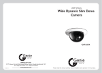
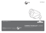
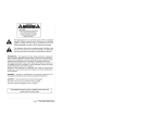
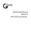
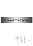
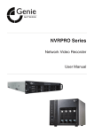
•W70SBIR, W70MBIR & W70LBIR
•
•
• Vandal Resistant IR Bullet Camera
•
•
• User Manual
• Safety Precautions
• DO NOT ATTEMPT TO DISASSEMBLE THE CAMERA.
Risk of Electric Shock, Do Not Open
CAUTION: TO REDUCE THE RISK OF ELECTRIC SHOCK, DO
NOT REMOVE COVER NO USER SERVICEABLE PARTS INSIDE
REFER SERVICING TO QUALIFIED SERVICE PERSON
2
•
This symbol is intended to alert the user to the presence of uninsulated dangerous voltage within
the product's enclosure that may be of sufficient magnitude to constitute a risk of electric shock to
persons.
•
This symbol is intended to alert the user to the presence of important operation and maintenance
instructions in the literature accompanying the appliance.
•
Vandal Resistant IR Bullet Camera
Warning
1. This product is patented for configuration, appearance and design; copying is not permitted.
•
2. If this product fails to operate normally contact your authorised distributor or service centre. Never
disassemble or modify the product in any way. Problems caused by disassembly, modification or
repair invalidates the product warranty.
•
3. Electromagnetic fields at specific frequencies may cause image interference.
•
4. Only use a standard regulated power adapter. Using any other adapter could result in fire, electric
shock or damage to the product.
•
5. Incorrectly connecting the power supply may result in fire, electric shock or damage to the product.
•
6. Do not connect multiple cameras to a single adapter. Exceeding the capacity may cause abnormal
heat generation or fire.
•
7. Securely plug the power cord into the power receptacle. A loose connection may result in fire.
•
8. When installing the camera on a wall or ceiling, fasten it safely and securely. A falling camera may
cause personal injury.
•
9. Do not place conductive objects (e.g. screwdrivers, coins etc.) on top of the camera.
•
10. Do not install the unit in humid, dusty locations.
•
11. If any unusual smell or smoke comes from the unit, please stop using the product. In such cases,
please immediately disconnect the power source and contact your local authorised distributor or
service centre.
Cautions
1. Do not drop objects on the products or apply strong shocks to it. Keep it away from locations subject
to excessive vibration or magnetic-field interference.
•
2. Do not install in a location subject to high temperatures (over 122°F or +50℃), low temperatures
(below 14°F or -20℃) it may cause a fire.
•
3. If want to relocate the installed product, turn off the power before moving or reinstalling it.
•
4. Remove the power plug from the outlet if there is a lightning storm. Neglecting to do so may cause
fire or damage to the product.
•
5. Avoid a location which is exposed to direct sunlight, or near heat sources. Neglecting to do so may
cause fire.
•
6. Install in a well-ventilated location.
•
7. Avoid aiming the camera directly towards extremely bright objects such as the sun, as this may
damage the image sensor.
•
Vandal Resistant IR Bullet Camera
3
Important Safety Instructions
1.
•
2.
•
3.
•
4.
•
5.
•
6.
•
7.
•
8.
Read these instructions
Keep these instructions for later use.
Pay attention to all warnings and adhere to them.
Follow all instructions.
Do not immerse this product in water.
Clean only with a lint free dry cloth.
Do not block any ventilation openings.
Do not install near any heat sources such as radiations, heat registers, or other products (including
amplifiers) that produce heat.
•
9. Protect the power cord from being walked on or being pinched, especially at power receptacles, and
the point where they exit from the camera.
•
10. Only use accessories specified by the manufacturer.
•
11. For added protection for this product during a lightning storm, or when it is left unattended and
unused for long periods of time, unplug it from the power.
•
12. Refer all servicing to qualified service personnel. Servicing is required when the product has been
damaged in any way, such as power supply cord or plug is damaged, it does not operate normally, or
has been dropped.
•
13. Do not operate the camera beyond its temperature, humidity or power source ratings. Operating
temperature: 14F-122F (-20℃-50℃), Humidity >85%
•
14. Do not point the camera towards the sun, spotlights or reflective surfaces.
•
15. Laser beams will damage the image sensor. Do not project laser beam directly into the lens of the
camera.
4
•
Vandal Resistant IR Bullet Camera
• Contents
Chapter 1 - W70SBIR Overview...................................................................6
•
•
•
•
•
•
Specification..................................................................................................................6
Features........................................................................................................................6
Product Parts................................................................................................................7
Operating Instructions...................................................................................................7
Installation.....................................................................................................................8
Adjusting the Monitoring Direction................................................................................9
•
•
•
•
•
•
•
Specification................................................................................................................10
Features.......................................................................................................................11
Package.......................................................................................................................11
Product Parts..............................................................................................................11
Operating Instructions.................................................................................................12
Installation...................................................................................................................13
Adjusting the Monitoring Direction..............................................................................14
•
•
•
•
•
•
•
Specification................................................................................................................15
Features......................................................................................................................16
Package......................................................................................................................16
Product Parts..............................................................................................................16
Operating Instructions.................................................................................................17
Installation...................................................................................................................18
Adjusting the Monitoring Direction..............................................................................19
Chapter 2 - W70MBIR Overview................................................................10
Chapter 3 - W70LBIR Overview.................................................................15
Chapter 4 - Typical CCD Phenomena.......................................................20
Chapter 5 - Troubleshooting.....................................................................21
Chapter 6 - Routine Maintenance.............................................................21
•
Vandal Resistant IR Bullet Camera
5
Chapter 1 - W70SBIR Overview
Specification
Model Number
W70SBIR
Image Sensor
CMOS
Video Format
PAL
Effective Pixels
720 (H) x 576 (V)
Horizontal Resolution
700 TVL
Minimum Illumination
0.1Lux @ (F1.2, AGC ON), 0 Lux with IR
Shutter Time
Auto
Day & Night
IR Cut Filter with Auto Switching
Sync System
Internal
Video Output
1Vp-p Composite Output (75Ω/BNC)
S/N Ratio
> 50dB
BLC
On
Lens
3.6mm IR 1.3MP
Angle of View
70°
Mount
M12
IR Light
2 Piece LED Array (2W Each)
IR Range
15m in Ideal Conditions
Weatherproof
IP66
Power Supply
DC12V
Power Consumption
Max. 2W (Max. 6W with IR LED’s ON)
Operating Temperature
- 20°C ~ 50°C
Bracket
3-Axis Cable Managed Bracket
Dimensions
117.5mm × 56mm × 65.8mm
Weight
*Design and Specifications are subject to change without notice.
Features
•
•
•
•
•
•
•
•
Built-in 3.6mm 1/3” IR 1.3 Megapixel Lens
Built-in ICR
2 Piece IR LED Array, Total Power 4W
Visible Range of up to 15m in Ideal Conditions
3-Axis Vertical / Horizontal / Rotational
Vandal Resistant
Water Resistant IP66
Package
Check the contents of the package. The following items are included:
•
• 1x User Manual
• 1x IR Dome Camera
• 3x Fixed Screws with Dielectric Covers
• 1x Dielectric Paper
• 1x L-Type Screw Driver
6
•
Vandal Resistant IR Bullet Camera
337.6g
Product Parts
•
Fixing Base
•
1
Locking Ring
•
2
IR LED Array
•
Photovaristor
5
1.
•
•
2.
•
•
3.
•
•
4.
•
•
5.
•
•
6.
•
3
•
4
Bracket Screw
Fixing Base
Fixes the camera to the ceiling or wall
Locking Ring
Locks the Camera Body to the Base
•
Side Screw
6
IR LED Array
Provides light source at night time
Photovaristor
Photocell to turn on or turn off the IR LED’s
Bracket Screw
Adjust and fix the horizontal angle of view
Side Screw
Adjust and fix the vertical angle of view
Operating Instructions
Connection
1. Connect one end of the BNC Cable to the terminals of a monitor or recording device.
•
2. Connect the other end of the BNC Cable to the camera VIDEO OUT terminal.
•
3. Then, plug the power adapter into the power receptacle. The image will be displayed when the monitor
is on.
•
Vandal Resistant IR Bullet Camera
7
Installation
Before Installation
•
Read the cautions before installation:
1. Make sure the installation location can support 5 times the total weight of the bullet camera.
2. Make sure the cable doesn’t get jammed inappropriately or allow the cable insulation to get damaged
during installation. This may result in a malfunction or a fire hazard.
•
3. Make sure that nobody is beneath the installation location.
Installing the Camera
•
The installation process is described below:
•
Step 1
Place the dielectric paper on the wall / ceiling (this is to protect the camera from damage by conducted
currents). Then, fix the camera base to the wall / ceiling with the 3 screws provided.
*Pay attention to the cable trough. Point it in the direction of the power supply if cables exit there.
Step 2
Attach the camera body to the fixing base.
•
•
•
•
•
•
•
•
Step 3
Fasten the camera body tightly using the gearing on the locking ring. The installation is complete.
•
Cable Trough
Cautions for Installation:
1. Allow the cable to pass through the hole in the middle before mounting the camera to the base.
•
2. If passing through the side, the cable must be put in the cable trough first before the camera is
mounted.
8
•
Vandal Resistant IR Bullet Camera
Adjusting the Monitoring Direction
1. Loosening the bracket screw allows you to rotate the camera body and bracket 180° in a horizontal
direction.
•
•
•
•
•
•
•
•
•
•
•
•
•
2. Loosening the side screw allows you to rotate the camera body or bracket in a vertical direction.
•
•
•
•
•
•
360°
•
•
•
•
•
•
•
•
3. By rotating the camera body or bracket downward 90° in a vertical direction (as above left picture), the
camera body or bracket can be rotated 360°.
•
Note: The camera body or bracket can be rotated 360° only when in the position indicated in the
above left photo
•
Vandal Resistant IR Bullet Camera
9
Chapter 2 - W70MBIR Overview
Specification
Model Number
W70MBIR
Image Sensor
Sony 1/3” Super HAD II CCD
Video Format
PAL
Effective Pixel
976 (H) × 494 (V)
Scanning System
2:1 Interlace
Sync System
Internal / External
Resolution
650TVL (Colour), 700 TVL (B&W)
Video Output
BNC 1.0Vp-p 75Ω
Burst Level
0.286Vp-p
S/N Ratio
>52dB
Minimum Illumination
0.01Lux @ F1.2 (Colour), 0.001Lux @ F1.2 (B&W)
Electronic Shutter
Auto / Manual
Exposure Control
AES / DC Drive Auto Iris / Video Drive Auto Iris
Auto / Manual / AIS
White Balance
ATW / Push / USER1 / User2 / Manual / Push Lock
AGC
Auto / Manual
OSD
Yes (Adjustment Inside Cover)
D/N Switch
Auto / Colour / Black & White / EXT1/ EXT2
IR
Smart IR
BLC
OFF / BLC / HLC
Image
Mirror / Lightness / Contrast / Sharpness / Colour / Gain
Digital WDR
OFF / ON 128 x WDR (52dB)
Motion Detection
OFF / ON
Privacy Masking
OFF / ON
Mirror
ON / OFF (Left / Right)
DNR
2 DNR
Sharpness
1 - 255 Adjustable
Chinese / English / Japanese / German / French / Russian /
Portuguese / Spanish
Menu Language
Lens
2.8-12mm 2MP IR Corrective
Angle of View
92° ~ 27.2°
Lens Mount
φ14
Iris
Fixed
IR Light
2 Piece LED Array (2.5W Each)
IR Range
Up to 20m in Ideal Conditions
Weatherproof
IP66
Power Supply
DC12V
Power Consumption
Max. 2W @ DC12V (Max. 7 W with IR LED’s ON)
Operating Temperature
-20°C~+50°C RH 85%
Bracket
3-Axis Cable Managed Bracket
Dimensions
178.2 x 64.5 x 76.5 mm
Weight
530g
*Design and Specifications are subject to change without notice.
10
•
Vandal Resistant IR Bullet Camera
Features
•
•
•
•
•
•
•
•
Built-in 2.8-12mm IR Corrective Lens
Built-in ICR
Easy Adjustment of Lens Focal Length
2 Piece IR LED Array
Visible Range up to 25m in Ideal Conditions
3-Axis Vertical / Horizontal / Rotational
Vandal Resistant
Weatherproof IP66
Package
Check the contents of the package. The following items are included:
•
• 1x User Manual
• 1x IR Bullet Camera
• 4x Fixing Screws with Dielectric Covers
• 1x Dielectric Paper
• 1x L-type Screwdriver
•
Product Parts
•
Fixing Base
•
1
Sunshield Screw
•
3
Sunshield
•
•
•
•
2
Bracket
Screw
•
1. Fixing Base
• Fixes the Camera to the ceiling or the wall
2.
•
•
3.
•
•
4.
•
Bracket Screw
Adjusts and sets the monitoring direction
Sunshield Screw
Fixes the Sunshield to the Camera Body
Sunshield
Protects the Camera Body
5. Photovaristor
• Photocell to switch the IR LED’s On and Off
•
6.
•
•
7.
•
•
8.
•
•
9.
•
•
•
4
Photovaristor
IR LED Array
6
•
Front Window
7
•
Bottom Cover
8
Bottom Cover Screw
5
9
IR LED Array
Provides a light source at night time
Front Window
Environmental protection for the Lens
Bottom Cover
Seals and protects the Focus and OSD controls
Bottom Cover Screw
Locks the Focus and OSD cover
Vandal Resistant IR Bullet Camera
11
•
•
Holder Screw
Connector Screw
10
11
•
Lens Zoom Cover
•
Lens Focus Lever
•
OSD Setup
•
Video Out Port
12
13
14
15
10. Holder Screw
• Adjusts and sets the monitoring direction
11. Connector Screw
• Adjusts and sets the monitoring direction
12. Lens Zoom Lever
• Adjusts the zoom ratio of the Lens
13. Lens Focus Lever
• Adjusts the focal length of the Lens
14. OSD Setup
• Sets the available OSD functions
15. Video Out Port
• Test Monitor connector for checking the image locally
Operating Instructions
Connection
1. Connect one end of the BNC Cable to the terminals of a monitor or recording device.
2. Connect the other end of the BNC Cable to the camera VIDEO OUT terminal.
•
3. Then, plug the power adapter into the power receptacle. The image will be displayed when the monitor
is on.
12
•
Vandal Resistant IR Bullet Camera
Installation
Before Installation
•
Read the cautions before installation:
1. Make sure the installation location can support 5 times the total weight of the bullet camera.
2. Make sure the cable doesn’t get jammed inappropriately or allow the cable insulation to get damaged
during installation. This may result in a malfunction or a fire hazard.
3. Make sure that nobody is beneath the installation location.
Installing the Camera
The installation process is described below:
Step 1
Place the dielectric paper on the wall / ceiling (this is to protect the camera from damage by conducted
currents). Then, fix the camera base to the wall/ceiling with the four screws provided.
*Pay attention to the cable trough. Point it in the direction of the power supply if cables exit there.
•
Cable Trough
Step 2
Attach the camera body to the fixing base.
Step 3
Fasten the camera body to the fixing base. The installation is now complete.
Cautions for Installation:
1. Allow the cable to pass through the hole in the middle before mounting the camera to the base.
•
2. If passing through the side, the cable must be put in the cable trough first before the camera is
mounted.
•
Vandal Resistant IR Bullet Camera
13
Adjusting the Monitoring Direction
•
Holder Screw
•
•
Bracket Screw
Connector Screw
The W70MBIR has a 3-axis gimbal design.
Loosen the holder, bracket and connector screws, then adjust the camera to the appropriate monitoring
position. After one direction is set, tighten the relevant fixing screw. Fully tighten all screws when all
adjustments are completed.
Changing Camera Functions
Loosen the bottom cover screw to open the bottom cover.
1. Use the video out port for connecting a test monitor to the camera to locally check the image output.
2. Set the required functions using the OSD setup.
3. Rotate the IR Illumination adjustment to adjust the IR intensity; appropriate to the application.
4. Adjust the focal length with the lens zoom and focus levers to obtain the correct field of view. Once a
clear and focused image is achieved, fully tighten the thumb screws.
5. After all adjustments are completed lock and tighten the bottom cover using the bottom cover screw.
14
•
Vandal Resistant IR Bullet Camera
Chapter 3 - W70LBIR Overview
Specification
Model Number
W70LBIR
Image Sensor
Sony 1/3” Super HAD II CCD
Video Format
PAL
Effective Pixel
976 (H) x 582 (V)
Scanning System
2:1 Interlace
Sync System
Internal / External
Resolution
650TVL (Colour), 700 TVL (B&W)
Video Output
BNC 1.0Vp-p 75Ω
Burst Level
0.286Vp-p
S/N Ratio
>52dB
Minimum Illumination
0.01Lux @ F1.2 (Colour), 0.001Lux @ F1.2 (B&W)
Electronic Shutter
Auto / Manual
Exposure Control
AES / DC Drive Auto Iris / Video Drive Auto Iris
Auto / Manual / AIS
White Balance
ATW / Push / USER1 / User2 / Manual / Push Lock
AGC
Auto / Manual
OSD
Yes (Adjustment Inside Cover)
D/N Switch
Auto / Colour / Black & White / EXT1/ EXT2
IR
Smart IR
BLC
OFF / BLC / HLC
Image
Mirror / Lightness / Contrast / Sharpness / Colour / Gain
Digital WDR
OFF / ON 128 x WDR (52dB)
Motion Detection
OFF / ON
Privacy Masking
OFF / ON
Mirror
ON / OFF (Left / Right)
DNR
2 DNR
Sharpness
1 - 255 Adjustable
Chinese / English / Japanese / German / French / Russian /
Portuguese / Spanish
Menu Language
Lens
2.8-12mm 2MP IR Corrective
Angle of View
92° ~ 27.2°
Varifocal Adjustment
Adjustment Inside Cover
Lens Mount
φ14
Day & Night
IR Cut Filter with Auto Switching
Iris
Fixed
IR Light
2 Piece LED Array (2.5W Each)
IR Range
Up to 30m in Ideal Conditions
Weatherproof
IP66
Power Supply
DC12V
Power Consumption
Max. 2W @ DC12V (Max. 7W with IR LED’s ON)
Heater
Optional (7W)
Operating Conditions
-20°C~50°C RH 85%; -50°C~50°C with Heater ON
Bracket
3-Axis Cable Managed Bracket
Dimensions (L x W x H)
259.6 x 109 x 111.8mm
Weight
996.5g
*Design and Specifications are subject to change without notice.
•
Vandal Resistant IR Bullet Camera
15
Features
•
•
•
•
•
•
•
•
Built-in 2.8-12mm IR 2MP Lens
Built-in ICR
Easy Lens Focal Length Adjustment
2 Piece IR LED Array, Total Power 7W
Visible Range up to 30m in Ideal Conditions
3-Axis Vertical/Horizontal/Rotational
Vandal Resistant
Weatherproof IP66
Package
Check the contents of the package. The following items are included:
•
• 1x User Manual
• 1x IR Bullet Camera
• 3x Fixing Screws with Dielectric Covers
• 1x Dielectric Paper
• 1x L-type Screwdriver
Product Parts
•
Fixing Base
•
Locking Ring
•
Bracket Screw
•
1
2
3
Sunshield Screw
•
4
Sunshield
•
16
5
•
IR LED Array
•
Photovaristor
6
Bottom Cover Screw
8
1. Fixing Base
• Fix the camera to the ceiling or wall
5. Sunshield
• Protects the Camera Body
2. Locking Ring
• Locks the Camera Body to the Fixing Base
6. IR LED Array
• Provides a light source at night time
3. Bracket Screw
• Adjusts and fixes the monitoring direction
7. Photovaristor
• Photocell to turn the IR LED’s On or Off
4. Sunshield Screw
• Fixes the Sunshield to the Camera Body
8. Bottom Cover Screw
• Locks the Focus and OSD cover
•
Vandal Resistant IR Bullet Camera
•
•
Side Screw
Bottom Cover
9
10
•
Video Out Port
•
IR Illumination Adjustment
•
9. Side Screw
• Adjusts and fixes the monitoring direction
•
10. Bottom Cover
• Seals and protects the Focus and OSD
controls
•
11. Video Out Port
• Test Monitor connector for checking the
image locally
•
11
OSD Setup
•
Lens Zoom Lever
•
Lens Focus Lever
12
13
14
15
12. IR Illumination Adjustment
• Adjusts the IR LED intensity
•
13. OSD Setup
• Sets the available OSD functions
•
14. Lens Zoom Lever
• Adjusts the zoom ratio of the Lens
•
15. Lens Focus Lever
• Adjusts the focal length of the lens
Operating Instructions
Connection
1. Connect one end of the BNC Cable to the terminals of a monitor or recording device.
2. Connect the other end of the BNC Cable to the camera VIDEO OUT terminal.
•
3. Then, plug the power adapter into the power receptacle. The image will be displayed when the monitor
is on.
•
Vandal Resistant IR Bullet Camera
17
Installation
Before Installation
•
Read the cautions before installation:
1. Make sure the installation location can support 5 times the total weight of the bullet camera.
2. Make sure the cable doesn’t get jammed inappropriately or allow the cable insulation to get damaged
during installation. This may result in a malfunction or a fire hazard.
3. Make sure that nobody is beneath the installation location.
Installing the Camera
The installation process is described below:
•
Cable Trough
Step 1
Place the dielectric paper on the wall / ceiling (this is to protect the camera from damage by conducted
currents). Then, fix the camera base to the wall/ceiling with the three screws provided.
*Pay attention to the cable trough. Point it in the direction of the power supply if cables exit there.
Step 2
Attach the camera body to the fixing base.
Step 3
Fasten the camera body tightly using the gearing on the locking ring. The installation is complete.
Cautions for Installation:
1. Allow the cable to pass through the hole in the middle before mounting the camera to the base.
•
2. If passing through the side, the cable must be put in the cable trough first before the camera is
mounted.
18
•
Vandal Resistant IR Bullet Camera
Adjusting the Monitoring Direction
1. Before tightening the locking ring you can rotate the whole Camera Body to the required surveillance
position.
2. Loosen the bracket screw and you can rotate the Camera Body horizontally according to your surveillance need. Tighten the bracket screw after you finish the adjustment.
3. Loosen the side screw and you can rotate the camera body vertically, according to surveillance need.
Tighten the side screw after you finish the adjustment.
Changing Camera Functions
Loosen the bottom cover screw to open the bottom cover.
1. Use the video out port for connecting a test monitor to the camera to locally check the image output.
2. Set the required functions using the OSD setup.
3. Rotate the IR Illumination adjustment to adjust the IR intensity; appropriate to the application.
4. Adjust the focal length with the lens zoom and focus levers to obtain the correct field of view. Once a
clear and focused image is achieved, fully tighten the thumb screws.
5. After all adjustments are completed lock and tighten the bottom cover using the bottom cover screw.
•
Vandal Resistant IR Bullet Camera
19
Chapter 4 - Typical CCD Phenomena
The following effects on the monitor screen are characteristics of CCD cameras. They do not indicate any
fault with the camera.
Smear
This can occur when the camera is pointed toward a very bright object, such as electrical lighting, the sun,
or a strong reflection. This phenomenon is caused by an electric charge induced by infrared radiation deep
in the photosensor. It appears as a vertical smear because the CCD imaging element uses an interline
transfer system.
Vertical Aliasing
When the camera is pointed toward vertical stripes or lines, they may appear jagged.
Blemishes
A CCD image sensor consists of an array of individual sensor picture elements (Pixels). A malfunctioning
sensor element causes a single pixel blemish in the picture. This is generally not a problem.
White Speckles
A CCD image pickup device uses accurate techniques to capture an image, however imperceptible
speckles may occasionally appear on the screen. This is related to the principles of a CCD mage sensor
pickup device and not a malfunction. The white speckles could appear under the following conditions:
• Using the camera in high temperatures
• When turning up the gain
Blooming
This is a phenomenon is which the light from very bright objects appears to overflow into neighbouring
areas of an image.
Note : If strong light enters a wide area of the image the screen may become dark. If this occurs, move the
camera away from the light source or adjust the iris to reduce the amount of light entering the lens.
20
•
Vandal Resistant IR Bullet Camera
Chapter 5 - Troubleshooting
•
If you encounter trouble in using the camera, please refer to the instructions below. For more
information, please consult your local authorised distributor or service centre.
Problem
Solution
Check the power supply and the cable, camera and monitor connections.
Check whether the camera is connected to the DC12V
power supply.
Adjust the display contrast of the monitor; Change the
location if the camera is exposed to intense light.
No Video Output
Malfunction
Light Image
Dark Image
Adjust the Brightness.
The situations below are not malfunctions of the camera.
Problem
Solution
May appear when the camera is exposed to intense
light.
When the camera is in a high temperature environment,
there may be fixed image clutter on the entire monitor
screen.
Vertical Streak
Fixed Image Clutter
When shooting at a ribbon-like object, a straight line or
something with a similar pattern, the image displayed on
the monitor may be serrated.
Jagged Image
Chapter 6 - Routine Maintenance
1. Regularly clean the dust and dirt from the lens surface of the camera with a dry lint free cloth to
maintain clarity of image.
•
2. Clean the camera body with dry soft cloth. For stubborn dirt, wipe it with a cloth dipped in a little
neutral detergent, and then dry the camera.
•
3. Do not use volatile chemicals, such as thinners, alcohol, benzene etc. to clean the camera, because
they can damage the surface coating, and even weaken the functionality and performance of the
camera.
•
Vandal Resistant IR Bullet Camera
21
Memo
22
•
Vandal Resistant IR Bullet Camera
Memo
•
Vandal Resistant IR Bullet Camera
23
•
• GENIE CCTV LTD.
CCTV House, City Park, Watchmead, Welwyn Garden City, Hertfordshire, AL7 ILT
• Tel: +44 (0) 1707 330541 Fax: +44 (0) 1707 330543
• www.geniecctv.com
•
•
•
Edition. GN-January 2014