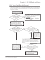
1
Preface Thank you for purchasing Pro-face's GP-37W2 Series Graphic Control Panel (hereafter referred to as either the "GP" or the "GP unit"). Please read this manual carefully as it explains, step by step, how to use the GP correctly and safely. Also, in this manual's examples, the Mitsubishi MELSEC-AnA Series PLC is used whenever possible, connected in a one-to-one relationship with a GP. <Note> 1) It is forbidden to copy the contents of this manual, in whole or in part, except for the user's personal use, without the express permission of the Digital Electronics Corporation of Japan. 2) The information provided in this manual is subject to change without notice. 3) This manual has been written with care and attention to detail; however, should you find any errors or omissions, please contact the Digital Electronics Corporation and inform us of your findings. 4) Please be aware that Digital Electronics Corporation shall not be held liable by the user for any damages, losses, or third party claims arising from the uses of this product. All Company/Manufacturer names used in this manual are the registered trademarks of those companies. © 2000, Digital Electronics Corporation GP-37W2 Series User Manual 1 Preface Table of Contents Preface ........................................................................................................................ 1 Table of Contents ...................................................................................................... 2 Essential Safety Precautions ................................................................................... 5 General Safety Precautions .................................................................................... 8 About GP-37W2 Series Models ............................................................................ 10 Package Contents ................................................................................................... 10 Separately Sold User Manual ............................................................................... 10 UL/c-UL(CSA) Approval ...................................................................................... 11 CE Marking ............................................................................................................. 11 CNS Standards ....................................................................................................... 11 Documentation Conventions ................................................................................. 12 CHAPTER 1 INTRODUCTION 1.1 Prior to Operating the GP ............................................................................ 1-1 1.2 System Design ................................................................................................. 1-2 1.3 Accessories ...................................................................................................... 1-4 CHAPTER 2 SPECIFICATIONS 2.1 General Specifications ................................................................................... 2-1 2.1.1 Electrical ............................................................................................ 2-1 2.1.2 Structural ............................................................................................ 2-1 2.1.3 Environmental ................................................................................... 2-2 2.2 Functional Specifications .............................................................................. 2-3 2.2.1 Display ............................................................................................... 2-3 2.2.2 Memory and Clock ............................................................................ 2-3 2.2.3 Interfaces ............................................................................................ 2-4 2.3 Interface Specifications ................................................................................. 2-5 2.3.1 Serial Interface................................................................................... 2-5 2.4 Part Names and Functions ........................................................................... 2-7 2.5 Dimensions ...................................................................................................... 2-8 2.5.1 External Dimensions ......................................................................... 2-8 2.5.2 Installation Fasteners ....................................................................... 2-9 2.5.3 Panel Cut Dimensions ....................................................................... 2-9 2 GP-37W2 Series User Manual CHAPTER 3 INSTALLATION AND WIRING 3.1 Installation ...................................................................................................... 3-1 3.1.1 Installation Procedure ....................................................................... 3-1 3.2 Wiring Cautions ............................................................................................. 3-4 3.2.1 Connecting the Power Cord .............................................................. 3-4 3.2.2 Grounding .......................................................................................... 3-5 3.2.3 I/O Signal Line Placement ................................................................ 3-5 3.3 Tool Connector ............................................................................................... 3-6 CHAPTER 4 OFFLINE MODE 4.1 Entering OFFLINE Mode ........................................................................... 4-1 4.1.1 When Turning the Power ON ........................................................... 4-1 4.1.2 From Forced Reset ............................................................................ 4-2 4.2 OFFLINE Mode Main Menu ....................................................................... 4-3 4.3 INITIALIZATION ......................................................................................... 4-4 4.4 SELF-DIAGNOSIS ........................................................................................ 4-6 4.5 Transferring Screen Data ............................................................................. 4-8 CHAPTER 5 INITIALIZING THE GP 5.1 Initialization Screen....................................................................................... 5-1 5.2 Initialization Items ......................................................................................... 5-2 5.3 SYSTEM ENVIRONMENT SETUP .......................................................... 5-3 5.3.1 SYSTEM SETUP .............................................................................. 5-3 5.3.2 SYSTEM AREA SETUP .................................................................. 5-4 5.3.3 GLOBAL WINDOW SETUP ........................................................... 5-6 5.3.4 CHARACTER STRING DATA SETUP .......................................... 5-7 5.4 SET UP I/O ................................................................................................... 5-10 5.4.1 SET UP SIO ..................................................................................... 5-10 5.4.2 COMMUNICATION SETUP ........................................................ 5-11 5.4.3 SET UP TOUCH PANEL ............................................................... 5-12 5.4.4 DISPLAY SETUP ............................................................................ 5-15 5.5 PLC SETUP .................................................................................................. 5-16 5.5.1 SET UP OPERATION SURROUNDINGS(1:1/n:1) ..................... 5-16 5.5.2 STATION SETUP(n:1).................................................................... 5-17 5.5.3 CUSTOMIZE SETUP (n:1) ............................................................ 5-19 GP-37W2 Series User Manual 3 Preface 5.6 INITIALIZE INTERNAL MEMORY .................................................... 5-21 5.7 SET UP TIME .............................................................................................. 5-21 5.8 SET UP SCREEN ........................................................................................ 5-22 5.9 FONT SETTING .......................................................................................... 5-23 CHAPTER 6 GP RUN MODE AND ERRORS 6.1 GP RUN Mode ............................................................................................... 6-1 6.1.1 After Powering Up the GP ................................................................ 6-1 6.1.2 Via OFFLINE Mode .......................................................................... 6-1 6.2 Troubleshooting.............................................................................................. 6-3 6.2.1 Possible Types of Trouble ................................................................. 6-3 6.2.2 Troubleshooting Flow Chart ............................................................. 6-4 6.2.3 No GP/Host Communication ............................................................ 6-7 6.2.4 Touch Panel Does Not Respond ....................................................... 6-9 6.3 SELF-DIAGNOSIS ...................................................................................... 6-10 6.3.1 GP SELF-DIAGNOSIS Item List ................................................... 6-10 6.3.2 SELF-DIAGNOSIS - Details........................................................ 6-11 6.4 Error Messages ............................................................................................. 6-13 6.4.1 Error Message List .......................................................................... 6-13 6.4.2 Error Message Details .................................................................... 6-15 CHAPTER 7 MAINTENANCE 7.1 Regular Cleaning ........................................................................................... 7-1 7.1.1 Cleaning the Display ......................................................................... 7-1 7.1.2 Installation Gasket Check/Replacement .......................................... 7-1 7.2 Periodic Check Points ................................................................................... 7-3 7.3 Changing the Backlight ................................................................................ 7-4 INDEX 4 GP-37W2 Series User Manual Preface Essential Safety Precautions This manual includes procedures that must be followed to operate the GP correctly and safely. Be sure to read this manual and any related materials thoroughly to understand the correct operation and functions of this unit. Safety Icons Throughout this manual the following icons are provided next to GP operation procedures requiring special attention. and provide essential safety information. The following is an example of these icons and their meanings: Warning Indicates situations where severe bodily injury, death or major equipment damage can occur. Caution Indicates situations where slight bodily injury or machine damage can occur. WARNINGS System Design • Do not create switches used to control machine safety operations, such as an emergency stop switch, as a GP touch screen icon. Be sure to install these switches as separate hardware switches, otherwise severe bodily injury or equipment damage can occur. • Please design your system so that equipment will not malfunction due to a communication fault between the GP and its host controller. This is to prevent any possibility of bodily injury or material damage. • The GP is not appropriate for use with aircraft control devices, aerospace equipment, central trunk data transmission (communication) devices, nuclear power control devices, or medical life support equipment, due to these devices’ inherent requirements of extremely high levels of safety and reliability. • When using the GP with transportation vehicles (trains, cars and ships), disaster and crime prevention devices, various types of safety equipment, non-life support related medical devices, etc. redundant and/or failsafe system designs should be used to ensure the proper degree of reliability and safety. GP-37W2 Series User Manual 5 Preface WARNINGS • After the GP’s backlight burns out, unlike the GP’s “Standby Mode”, the touch panel is still active. If the operator fails to notice that the backlight is burned out and touches the panel, a potentially dangerous machine missoperation can occur. Therefore, do not use GP touch switches for the control of any equipment safety mechanisms, such as Emergency Stop switches, etc. that protect humans and equipment from injury and damage. If your GP's backlight suddenly turns OFF, use the following steps to determine if the backlight is actually burned out. 1) If your GP is not set to "Standby Mode" and the screen has gone blank, your backlight is burned out. 2) Or, if your GP is set to Standby Mode, but touching the screen does not cause the display to reappear, your backlight is burned out. GP Wiring • To prevent an electric shock, be sure to confirm that the GP's power cord is not connected to the main power when connecting any cords, cables or lines to the GP. • Do not use power beyond the GP's specified voltage range. Doing so may cause a fire or an electric shock. GP Start-up and Maintenance • The GP uses a lithium battery for backing up its internal clock data. If the battery is incorrectly replaced, the battery may explode. To prevent this, please do not replace the battery yourself. When the battery needs to be replaced, please contact your local GP distributor. 6 GP-37W2 Series User Manual Preface WARNINGS GP Installation • High voltage runs through the GP. Never disassemble the GP, otherwise an electric shock can occur. • Do not modify the GP unit. Doing so may cause a fire or an electric shock. • Do not use the GP in an environment where flammable gasses are present, since operating the GP may cause an explosion. CAUTIONS GP Installation • Be sure to securely connect all cable connectors to the GP. A loose connection may cause incorrect input or output. GP Wiring • Ground the GP's FG line separately from other units’ FG lines. Putting these FG lines too close may cause an electric shock or unit malfunction. Be sure to use a grounding Ω or less and a 2mm2 or thicker wire, or resistance of 100Ω your country’s applicable standard. • When wiring the GP, be sure that the rated voltage and terminal layout are within the designated range. If the voltage supplied differs from the rated voltage, or incorrect wiring or grounding is performed, it may cause a fire or unit malfunction. • Use only the designated torque to tighten the GP's terminal block screws. If these screws are not tightened firmly, it may cause a short-circuit, fire, or GP unit malfunction. • Be careful that metal filings and wiring debris do not fall inside the GP, since they can cause a fire, GP unit malfunction, or operation error. GP-37W2 Series User Manual 7 Preface CAUTIONS GP Start-up and Maintenance • The liquid crystal panel contains a powerful irritant and if for any reason the panel is damaged and this liquid contacts any part of your body, be sure to wash that area with running water for 15 minutes. If any of this liquid enters your eye, flush your eye for 15 minutes with running water and contact a physician. GP Disposal • When this unit is disposed of, it should be done so according to your country's regulations for similar types of industrial waste. General Safety Precautions • Never strike the touch panel with a hard, heavy or pointed object, or press on the touch panel too strongly, since it may damage the unit. • If the GP is used in an environment with temperatures and humidity in excess of the allowed range, the GP may malfunction and/or its operation life may be shortened. • Avoid restricting the GP’s naturally occurring ventilation, or storing or using the GP in an environment that is too hot. • Do not use this unit in areas where large, sudden temperature changes can occur. These changes can cause condensation to form inside the unit., possibly causing the unit to malfunction. • Do not allow water, liquids, metal or charged particles to enter inside the GP’s case, since they can cause either a GP malfunction or an electrical shock. • Avoid using or storing the GP in direct sunlight, or in excessively dusty or dirty environments. • Because the GP is a precision instrument, do not store or use the unit where large shocks or excessive vibration can occur. • Do not store or use the GP where chemicals (such as organic solvents, etc.) and acids can evaporate, or where chemicals and acids are present in the air. • Do not use paint thinner or organic solvents to clean the GP. 8 GP-37W2 Series User Manual Preface • Do not store or operate the LCD display in areas receiving direct sunlight, since the sun’s UV rays may cause the LCD display’s quality to deteriorate. • Storing this unit in areas at a temperature lower than is recommended in this manual’s specifications may cause the LCD display’s liquid to congeal, which may damage the panel. Conversely, if the storage area’s temperature becomes higher than the allowed level, the LCD’s liquid will become isotropic, causing irreversible damage to the LCD. Therefore, be sure to store the panel only in areas where temperatures are within those specified in this manual. • Due to the possibility of unforeseen accidents, be sure to back up the GP’s screen data regularly. About the GP's Display Panel • The GP's currently displayed data, its voltage*1 and brightness setting each affect the intensity of Contouring. (i.e, when some parts of the screen are brighter than others, creating a wavelike pattern) • There are minute grid-points (dark and light) on the Display Panel's surface. This is part of the GP's design and not a defect. • Shadows may appear at the top of the LCD. This is normal for an LCD display. • Sometimes the display area may look as if the display colors have changed. This is a common attribute of LCD's and is not a defect. • Displaying a single image for long periods can cause an afterimage to remain when the display is changed to another screen. To prevent this effect: • Use the GP's "Stand-by Mode", which automatically turns the screen OFF when there is no input for a specified period of time. 5.3.1 System Setup • Write “FFFFh” in the System Data Area’s “Screen Display Off” address *2 to turn the screen display OFF when there is no input for a specified period of time. • Do not display any single screen for a long period of time. Try to periodically change the screen display. *1 If the GP's voltage is at the very low end of its allowable range, it may effect the intensitly of contouring. *2 The following addresses assume all System Data Area settings are entered. If they are not all entered, the correct word address may be different from those given here. When using the Direct Access Method — System Data Area’s word address +9 GP-37W2 Series User Manual 9 Preface About GP-37W2 Series Models The GP-37W2 Series refers to the following GP model number: Series Model Name GP-37W2 Series GP-37W2B Model Type Comments GP37W2-BG41-24V CE Marked, UL/cUL (CSA), CNS Approved unit Package Contents The GP's packing box contains the items listed below. Please check to confirm that all items shown below have been included. GP Unit Installation Guide (1) GP37W2-BG41-24V Installation Guide GP-37W2 Series Unit Installation Fasteners (4/set) This unit has been carefully packed, with special attention to quality. However, should you find anything damaged or missing, please contact your local GP distributor immediately for prompt service. Separately Sold User Manual This guide (GP-37W2 Series User Manual) is sold separately. GP-37W2 Series User Manual (1) GP-37W2 Series User Manual 10 GP-37W2 Series User Manual Preface UL/c-UL(CSA) Approval The GP37W2-BG41-24V is a UL/c-UL (CSA) listed product. (UL file No.E177793) This unit conforms to the following standards: • UL1950, Third Edition, dated July 26th, 1995 Standard for Safety of Information Technology Equipment, including Electrical Business Equipment. • CAN/CSA-C22.2, Nos. 142 and 213-M1987 Standard for Safety of Information Technology Equipment, including Electrical Business Equipment. GP377-BG41-24V (UL Registration Model: 2880052-01) <Cautions> • The GP must be used as a built-in component of an end-use product. • Machinery which has a GP installed in it requires UL/c-UL (CSA) inspection for the combination of this unit and the machinery. • If the GP is installed so as to cool itself naturally, be sure to install it in a vertical panel. Also, be sure that the GP is mounted at least 100 mm away from any adjacent structures or equipment. If these requirements are not met, the heat generated by the GP's internal components may cause the unit to fail to meet UL/cUL (CSA) standard requirements. CE Marking The GP377-LG41-24V, and GP377-SC41-24V are CE marked products that conforms to EMC directives EN55011 class A and EN50082-2. * For detailed CE marking information, please contact your local GP distributor. CNS Standards The GP37W2-BG41-24V unit complies with the following CNS standards. • CNS13438 (Class A) <Caution> The GP is an Industrial Device (Class A Device). Use of this device in a residential environment may cause radio wave interference with nearby electrical devices. If interference does occur, please try a variety of countermeasures to solve the problem. GP-37W2 Series User Manual 11 Preface Documentation Conventions The list below describes the documentation conventions used in this manual. Symbol Meaning Indicates important information or procedures that must be followed for correct and risk-free software/device operation. *1 1) , 2) Indicates useful or important supplemental information. Indicates steps in a procedure. Be sure to perform these steps in the order given. Refers to useful or important supplemental information. Provides useful or important supplemental information. GP Screen Indicates the GP-PRO/PBIII for Windows screen editor software. Editor Abbreviation for Programmable Logic Controller. PLC 12 GP-37W2 Series User Manual 1. Prior to Operating the GP 2. System Design Chapter 1 1.1 3. Optional Equipment Introduction Prior to Operating the GP Be sure to follow these steps when creating projects for the GP unit. 1 Preparation 2 Screen Design Before using the GP, check that all required hardware is present and read all specification, wiring, and installation information. Chapter 2, "Specifications", and Chapter 3, "Installation and Wiring" Create a sample screen and design a Tag layout, with the Screen layout sheets and Tag lists provided in the Editor software. 3 Select GP and PLC types GP-PRO/PBIII for Windows Operation Manual (included with the screen creation software) Using the input areas provided, select the GP and the PLC types to be used. 4 Create Screen/ Run Screen Setup GP-PRO/PBIII for Windows Operation Manual (included with the screen creation software) Set up the screen and tags in your screen editing software according to your Screen Design. GP-PRO/PBIII for Windows Operation Manual and Tag Reference Manual (included with the screen creation software) 5 Transfer Screen Data Transfer the data from the Screen design software on your PC to the GP unit using the Downloading Cable. GP-PRO/PBIII for Windows Operation Manual (included with the screen creation software) 6 GP/Host Connection Set up the GP so that it can receive data from the Host (PLC). 7 Connect the GP Chapter 4-3, "Initialize", and the PLC Connection Manual Link the GP with the host (PLC) using the appropriate connection cable (different cables may be necessary for different hosts), and then run the unit. GP-PRO/PBIII for Windows PLC Connection Manual GP-37W2 Series User Manual 1-1 Chapter 1 - Introduction 1.2 System Design The diagrams on the following pages illustrate the peripheral equipment available for the GP unit. Screen Editing Environment GP Operating Environment GP Unit GP-37W2-BG41-24V GP-PRO/PBIII for Windows Data Transfer Cable GPW-CB02 Personal Computer *1 Printer (Commercially available type) Bar Code Reader (Recommended Units *2 ) RS-232C Cable*3 GP410-IS00-O RS-422 Cable*3 Host Controller GP230-IS11-O GP230-IS12-O (for Multilink cable) RS-422 Connector*3 Terminal Adapter PLC etc. GP070-CN10-O Mitsubishi PLC A, Q, C, FX Series' 2 Port Adaptor II 2 Port Adaptor II Cable GP070-MD11 GP070-MDCB11 Mitsubishi PLC A-Series Program Port I/F Cable GP430-IP10-O Mitsubishi PLC FX-Series Program Port I/F Cable GP430-IP11-O GP Interfaces Tool Connector Serial Interface PLC Interfaces RS-232C Port RS-422 Port Programming Port Personal Computer Interfaces Printer Interface 1-2 GP-37W2 Series User Manual Chapter 1 - Introduction *1 For range of compatible PCs refer to the following manual. GP-PRO/PBIII for Windows Operation Manual (included with the screen creation software) *2 Recommended Units: Aimex Corporation Reading Width BR-331 PC2 60mm (Pen type) 80mm 100mm OPT Electronics Touch Scanner Type OPT-1105-RSK 98 Set OPT-5105-RSK 98 Set OPL-6735-RSK 98 Set Tohken Reading Width 65mm 82mm 105mm Touch Scanner Type TCD-5510M TCD-5510L TCD-5510W *3 For information about compatible PLC types and software, please refer to GP-PRO/PBIII for Windows PLC Connection Manual (included with the screen creation software) GP-37W2 Series User Manual 1-3 Chapter 1 - Introduction 1.3 Accessories All optional equipment listed below is produced by Digital.Electronics Corporation. Available Software Product Name GP-PRO/PB III for Windows Ver.4.0 or later *1 Model No. GPW-PB01M-V40 <CD-ROM> Description Software to be used to create the GP's screen data using a personal computer. *1 When using the GP-PRO/PBIII for Windows Ver. 4.0 software, the additional GP37W2 Update CD is also required. Tool Connector Product Name Model No. Screen Data Transfer Cable GPW-CB02 Memory Loader II GP070-LD01-O Description Connects the GP to a personal computer. Transfers screen data and user program(s). Copies data (system and screen data) from one GP to another GP. Rev. H or later Serial Interface Product Name RS-232C cable *1 RS-422 cable *1 RS-422 cable Connector terminal block converter Model No. Description GP410-IS00-O GP230-IS11-O GP230-IS12-O(for Multilink) GP070-CN10-O 2 Port Adapter II GP070-MD11 2 Port Adapter II Cable Mitsubishi A Series Programming Port I/F cable Mitsubishi FX Series Programming Port I/F cable GP070-MDCB11 GP430-IP10-O GP430-IP11-O Interface cable between the host (PLC) and GP. Adapter to convert serial data to RS-422 format. Interface unit that allows use of both GP and Mitsubishi A,Q, C and FX series equipment in the same location. Connects the GP to 2 Port Adapter II. Connects directly to Mitsubishi's PLC I/F Programming Console. Simultaneous use of program console, however, is not possible. *1 For detailed information about range of connectable PLCs. GP-PRO/PBIII for Windows PLC Connection Manual (included with the screen creation software) 1-4 GP-37W2 Series User Manual Chapter 1 - Introduction Option Product Name Screen Protection Sheet Model No. GP37W2-DF00 Description Disposable protective and dirtresistant sheet for the GP's screen. The GP's touch panel can be used with this cover sheet attached. Maintenance Items These optional items were included in either the GP itself or in its packing box. These items are sold separately as optional maintenance items. Product Name Installation fastener Model No. Description Fasteners to attach the GP to a panel. GP070-AT 01 Installation gasket GP37W2-WP00-MS GP-37W2 Series User Manual Provides a moisture resistant seal when installing the GP. Same as the seal included in the GP's original equipment package. 1-5 1.4 2-Port Feature Overview You can now use Mitsubishi’s GPP software (ladder programming software) on your PC while you connect the Mitsubishi PLC to the GP and the GP to your PC. You can send ladder logic data to and from the PLC, via the GP’s Internal 2 portfeature.With the GP37W2 Series unit, you can use the 2-Port feature by simply connecting the GP and your PC via the data transfer cable (GPW-CB02) without using the external 2-Port Adapter. For information about PLC types and GP compatibility with GP-37W2 Series units, refer to GP-PRO/PBIII for Windows PLC Connection Manual (included with the GP screen creation software) When Using GP-37W2 Series unit’s Internal 2-Port feature *1 GP Connected to the Serial I/F via the Programmer I/F Cable Connect to the tool connector via Data Transfer Cable (GPW-CB02) Connect to Programmer Port PC with Mitsubishi’s GPP software installed Mitsubishi PLC (compatible types only) When Using the External 2-Port Adapter Cable *2 GP Connected to GP’s Serial I/F Digital's 2-Port Adapter II (GP070-MD11) Connect to Programmer Port or Mitsubishi PLC (compatible types only) PC with Mitsubishi’s GPP software installed, or a Programming Console *1 The Device Monitor feature can also be used at the same time. For details about the device monitor function, refer to GP-PRO/PBIII for Windows PLC Connection Manual (included with the GP screen creation software) *2 GP-37W2 Series units can also use the 2-Port Adapter II. 1-6 GP-37W2 Series User Manual Internal 2-Port Feature Usage Notes • To use the Internal 2-Port feature, you will need to adjust your GP’s settings. For information about these settings, refer to GP-PRO/PBIII for Windows PLC Connection Manual (included with the GP Screen creation software) • This feature can be used only while the GP is in ONLINE mode. • Since the internal 2-Port feature uses the GP’s single tool connector, you will not be able to use optional equipment which requires the tool connector (i.e. a Barcode Reader, etc.) • If you transfer screen data while the GP is in ONLINE mode, the screen will not change to the data transfer screen automatically. Thus, you will need to change the screen manually to the OFFLINE mode's [Main Menu/ Transfer] screen. 4.5 Transferring Screen Data • Peripheral equipment which cannot be connected to the GP's tool connector (such as a Programming Console) is not compatible with the GP's Internal 2Port feature. To use this type of equipment, you will need to use the external 2Port Adapter II. GP-37W2 Series User Manual 1-7 Memo 1-8 GP-37W2 Series User Manual Chapter 2 2.1 1. General Specifications 4. Names and Functions of GP Parts 2. Functional Specifications 5. Graphic Panel Dimensions 3. Interface Specifications Specifications General Specifications 2.1.1 Electrical DC24V+15% DC20.4 to DC27.6V Rated Voltage 20W or less Power Consumption 2ms or less Allowable Voltage Drop AC1000V 10mA for 1 minute Voltage Endurance (between charging and FG terminals) Insulation Resistance 20M Ω or higher at DC500V (between charging and FG terminals) Input Voltage 2.1.2 Environmental Ambient Operating Temperature 0oC to +50oC Storage Temperature -20oC to +60oC 20%RH to 85%RH (No condensation) Ambient Humidity Air Purity Level Atmosphere Atmospheric Pressure Less than 0.1mg/m 3 of conductive dust Free of corrosive gasses 800 to 1114hPa (2000meters or lower) Vibration Resistance 10Hz to 25Hz (19.6m/s2 in X, Y, Z directions for 30min.) Noise Voltage: 1000Vp-p Noise Immunity (via noise simulator) Pulse Duration: 1x10⁻⁶sec. Arise T ime: 1ns Electrostatic Discharge Immunity 6kV (complies with IEC 61000-4-2 Level 3) GP-37W2 Series User Manual 2-1 Chapter 2 - Specifications 2.1.3 Structural Grounding Ratings (Front face of installed unit) Weight Cooling Method External Dimensions 100Ω or less, or your country's applicable standard *1 *2 Equivalent to IP65f (JEM 1030) NEMA#250 T YPE4X12 1.1kg [2.4lb] or less (main unit only) Natural air circulation W207[8.17] x H157 [6.18] x D58 [2.28] mm[in.] (main unit only) *1 Grounding requirements differ from country to country. Be sure to confirm your work environment requirements prior to installation. For further information, please contact your Pro-face distributor. *2 The front face of the GP unit, installed in a solid panel, has been tested using conditions equivalent to the standard shown in the specification . Even though the GP unit’s level of resistance is equivalent to the standard, oils that should have no effect on the GP can possibly harm the unit. This can occur in areas where either vaporized oils are present, or where low viscosity cutting oils are allowed to adhere to the unit for long periods of time. If the GP’s front face protection sheet becomes peeled off, these conditions can lead to the ingress of oil into the GP and separate protection measures are suggested. Also, if non-approved oils are present, it may cause deformation or corrosion of the front panel’s plastic cover. Therefore, prior to installing the GP be sure to confirm the type of conditions that will be present in the GP’s operating environment. If the installation gasket is used for a long period of time, or if the unit and its gasket are removed from the panel, the original level of the protection cannot be guaranteed. To maintain the original protection level, you need to replace the installation gasket regularly. 3. 2-2 GP-37W2 Series User Manual Chapter 2 - Specifications 2.2 Functional Specifications 2.2.1 Display Colors Monochrome LCD Blue Mode (Monochrome) Backlight CCFL (lifespan = more than 25,000 hours, when continuously lit) Resolution 320 x 240pixels Nominal Display Area W115.2[4.54] x H86.4(3.40) mm[in.] Contrast Control 8 levels of adjustment available via touch panel. Language Fonts ANK : 158 types, Kanji : 6962 types (including 607 non-kanji characters) ASCII, Chinese, Korean, and T aiwanese fonts are available Type Text 8x8 dot font 40 Char. per row, 30 rows 8x16 dot font 40 Char. per row, 15 rows 16x16 dot font 20 Char. per row, 15 rows 32x32 dot font 10 Char. per row, 7 rows Both height and width can be expanded 1, 2, 4, or 8 times. Font Sizes *1 Display Sizes Touch Panel 8X8, 8X16, 16X16 and 32X32 dot fonts Resistive Film - 16X12 Keys/Screen (1 or 2 point touch) *1 The display font will differ depending on which (country's) character, or which size refer to Chapter 5.9 Font you select. For detailed information Setting. GP-37W2 Series User Manual 2-3 Chapter 2 - Specifications 2.2.2 Memory and Clock Application Internal Clock Accuracy *1 *2 1MB FEEPROM *1 *2 + 65 seconds/month (at 25oC) A Lithium battery's lifetime is: 10 years when the battery's ambient temperature is under 40 oC 4.1 years when the battery's ambient temperature is under 50 oC 1.5 years when the battery's ambient temperature is under 60 oC When used for backup: Approximately 60 days, with a fully charged battery Approximately 6 days, with a half-charged battery The GP's internal clock has a slight error. At normal operating temperatures and with the GP's power turned OFF, i.e. in "backup mode", the degree of error is 65 seconds per month. Variations in operating conditions and battery life can cause this error to vary from -380 to +90 seconds per month. For systems where this degree of error will be a problem, the user should be sure to monitor this error and make adjustments when required. 2.2.3 Interfaces Serial Interface Asynchronous Transmission Method: RS232C/RS422 Data Length: 7 or 8 bits Stop Bit: 1 or 2 bits Parity: None, Odd or Even Data T ransmission Speed: 2400 to 115.2kbps Asynchronous TT L level nonprocedure command I/F Tool Connector <During Program Development> For connecting the Data Transfer cable when downloading data the GP-PRO/PBIII screen editor software. <During Standard Operation> When using the 2-Port function, and for connecting peripheral equipment, i.e. a bar code reader, etc. 2-4 GP-37W2 Series User Manual Chapter 2 - Specifications 2.3 Interface Specifications 2.3.1 Serial Interface Pin Arrangement SIO 1 14 25 13 Pin # 1 2 3 4 5 6 7 8 9 10 11 12 *1 13 *1 14 15 16 17 18 19 20 21 22 23 24 25 Signal Name Condition FG Frame ground SD Send data (RS-232C) RD Receive data (RS-232C) RS Request send (RS-232C) CS Clear send (RS-232C) NC No connection SG Signal ground CD Carrier detect (RS-232C) TRMX Termination (RS-422) RDA Receive data A (RS-422) SDA Send data A (RS-422) RESERVE Reserved RESERVE Reserved VCC 5V±5% output 0.25A SDB Send data B (RS-422) RDB Receive data B (RS-422) NC No connection CSB Clear send B (RS-422) ERB Enable receive B (RS-422) ER Enable receive (RS-232C) CSA Clear send A (RS-422) ERA Enable receive A (RS-422) BUZZ GND External buzzer ground NC No connection BUZZ OUT External buzzer output *1 #12 and #13 are RESERVED; do not connect to these pins. Recommended Connector: Dsub25pin plug XM2A-2501<made by OMRON> Recommended Cover: Jack Screws: Dsub25pin cover XM2S-2511<made by OMRON> XM2Z-0071<made by OMRON> Use rough metric type M2.6x0.45 p threads used to secure the cable's set screws. Recommended Cable: CO-MA-VV-SB5PX 28AWG <made by HITACHI Cable Ltd.> To confirm your PLC's connection specifications PLC Connection Manual (included with the screen creation software) GP-37W2 Series User Manual 2-5 Chapter 2 - Specifications When creating your own cable, follow the instructions listed below: <With RS-422> • The following pairs of pin #'s must be connected to each other. #18 (CSB) <—> #19 (ERB) #21 (CSA) <—> #22 (ERA) • When connecting the RS-422 cable and the #9 (TRMX) and #10 (RDA) points, a Ω is added between RDA and RDB. termination resistance of 100Ω • When making a cable for a Memory Link system, be sure to use a 4-wire type. <With RS-232C> cDo not use the following pins: 9 (TRMX), 10 (RDA), 11 (SDA), 15 (SDB), 16 (RDB), 18 (CSB), 19 (ERB), 21 (CSA), 22 (ERA). • The #1 (FG) terminal should only be connected if it is required by the device being connected to. <Buzzer Output> • #23 (BUZZ GND) and #25 (BUZZ OUT) are used for Buzzer Output. Internal Circuit Buzzer Buzzer Output SIO 25pin Optical Isolation Can drive a DC5V to DC24V buzzer at up to 0.3A SIO 23pin GP-37W2 unit (internal circuit) Connect the #1 (FG) terminal only if it is required by a connected device. • This unit’s RS485(RS422) port is not isolated, therefore, it is important that you connect the SG/GND (Signal Ground) terminals. If this is not done, the RS485(RS422) circuit may be damaged. • Pin 14 (VCC) DC5V output is not protected. To prevent damage or unit malfunction, be sure to use only the designated level of current. 2-6 GP-37W2 Series User Manual Chapter 2 - Specifications 2.4 Part Names and Functions A:Display Panel The GP monitor screen displays the screen setup and corresponding PLC host data. B: Touch Panel Performs any screen change operations and sends data to the PLC. C: Status LED Lights green while the power is ON. C A,B D: Power Input Terminal Block The input and ground terminals for the power cable. D E F E: Serial Interface Used for the RS-232C and RS-422 (Serial) cables. Is connected to the Host (PLC). F: Tool Connector The Data Transfer cable, Bar Code Reader or Memory Loader can be connected here. GP-37W2 Series User Manual 2-7 Chapter 2 - Specifications 2.5 Dimensions 2.5.1 External Dimensions For detailed dimension information, please contact your local GP distributor. Unit: mm [in.] Top 191.2 [7.53] Front 207 [8.15] Side 58 [2.28] 2-8 141.2 [5.56] 157 [6.18] 6 [0.24] GP-37W2 Series User Manual Chapter 2 - Specifications 2.5.2 Installation Fasteners Unit: mm [in.] 31 [1.22] 16 [0.63] 11 [0.43] 19.5 [0.77] 10 [0.39] M5 2.5.3 GP Panel-Cut Dimensions Unit: mm [in.] 4-R3 or less GP-37W2 Series User Manual [ 5.57+0.04 ] 0 [ 7.54 +0.04 ] 0 +1 141.5 0 +1 191.5 0 2-9 Memo 2-10 GP-37W2 Series User Manual 1. Installation 2. Wiring Cautions 3. GP Tool Connector Chapter 3 3.1 Installation and Wiring Installation 3.1.1 Installation Procedure Before installing the GP into a cabinet or panel, check that the installation gasket is securely attached to the unit. It is strongly recommended that you use the gasket since it Installation gasket absorbs vibration in addition to repelling water. Rear of GP Place the GP on a level surface with the display panel facing downward. Check that the GP’s installation gasket is seated securely into the gasket’s groove, which runs around the perimeter of the panel’s frame. For details about installing the gasket, refer to 7.1.2 Installation Gasket Replacement Creating a Panel Cut Out Create the correct sized opening required to install the GP, using the installation dimensions given. 2.5.3 “GP Panel Cut Out Dimensions” The installation gasket, installation brackets and attachment screws are all required when installing the GP. Panel Cut Out Area • Check that the installation panel or cabinet's surface is flat, in good condition and has no jagged edges. • Panel thickness should be from 1.6mm (0.06in.) to 10mm (0.4in.). 1.6mm(0.06in.) to 10mm(0.4in.) Decide the panel’s thickness based on the level of panel strength required. GP-37W2 Series User Manual 3-1 Chapter 3 - Installation and Wiring • For easier maintenance, operation, and better ventilation, be sure to install the GP at least 100mm [3.94in] away from adjacent structures and other equipment. • Be sure that the ambient operation temperature and the ambient humidity are within their designated ranges. • Be sure that heat from surrounding equipment does not cause the GP to exceed its standard operating temperature. • When installing the GP in a slanted panel, the panel face should not incline more than 30o. • When installing the GP in a slanted panel, and the panel face inclines more than 30o, the ambient temperature must not exceed 40oC. You may need to use forced air cooling (fan, A/C) to ensure the ambient operating temperature is 40oC or below. • When installing the GP vertically, orient the unit so that the Power Terminal Block is vertical, not horizontal. 3-2 GP-37W2 Series User Manual Chapter 3 - Installation and Wiring Installing the GP 1. Insert the GP into the installation panel from the front. 2. Hook the mounting bracket through each of the four bracket insertion slots on the top and bottom of the GP. Two (2) additional slots on both sides of the GP unit can be used, if greater strength is needed. If these are used, additional (optional) fasteners will be required. Panel hook 3. Slide the mounting bracket back. GP-37W20 Series User Manual 3-3 Chapter 3 - Installation and Wiring 4. Tighten the 4 mounting bracket screws by turning the screws, little by little, in a crisscross pattern. Excessive tightening may damage the GP or the panel. A torque of only 0.5 to 0.6 N•m is required to ensure a waterproof seal. Depending on the condition of the panel, increasing the number of the mounting brackets may increase the level of water resistance. 3-4 GP-37W2 Series User Manual Chapter 3 - Installation and Wiring 3.2 Wiring Cautions 3.2.1 Connecting the Power Cord WARNINGS • To avoid electric shocks, be sure the GP unit’s power cord is unplugged from the power outlet when connecting the cord’s power terminals to the GP. • The GP-37W2 accepts DC24V power input only. Using an incorrect power supply will result in damage to both the power supply and the GP. • Be sure to re-attach the GP Terminal Strip’s clear plastic cover after completing wiring. If the cover is not installed, it may lead to an electric shock. • When the FG terminal is connected, be sure the wire is grounded. Not grounding the GP unit will result in excessive noise. • To prevent the Ring Terminals from causing a short when the terminal block attachment screws are loosened, be sure to use sleevetype Ring Terminals. • Wherever possible, use thick wires (max 2mm2) for power terminals, and twist the exposed wire ends when connecting the Ring Terminals. • Please use the following size crimp-on type Ring Terminals. over Ø3.2mm under 6.0mm Connect the GP Power Supply Terminals as follows: 1. Be sure that the GP's Power Cord is not plugged in to the power supply. FG 2. Remove the Terminal Strip's clear plastic cover. 3. Remove the screws from the three (3) middle terminals, position the Ring Terminals as shown above and reattach the screws. (Check each wire to make sure the connections are correct and only 0.5 to 0.6 N•m of force.) + Power Terminal Block + - FG Rear of GP-37W2 Crimp-on Ring Terminals 4. Re-attach the Terminal Strip's clear plastic cover. GP-37W20 Series User Manual 3-5 Chapter 3 - Installation and Wiring 3.2.2 Grounding CAUTIONS Do not use common grounding, since it can lead to an accidet or machine malfunction. (a) Exclusive Grounding (BEST) *1 Connect the FG terminal found at the back of the unit to an exclusive ground. [diagram (a)]. • Check that the grounding resistance is less than 100Ω. • FG and SG are connected inside the GP. *1 (b) Common Grounding (OK) (c) Common Grounding (Not OK) • The grounding wire should have a cross sectional area greater than 2mm2. Set the connection point as close to the GP unit, and make the wire as short, as possible. When using a long grounding wire, replace the thin wire with a thicker wire, placed in a duct. If exclusive grounding is not possible, use a common connection point. [diagram (b)] If the equipment does not function properly when grounded, disconnect the ground wire from the FG terminal. 3.2.3 Placement of I/O Signal Lines Input and output signal lines must be separated from the power control cables for operating circuits. If this is not possible, use a shielded cable and connect the shield to the GP's frame. *1 Use a grounding resistance of less than 100Ω and a 2mm2 or greater thickness wire, or your country’s applicable standard. For details, contact your local GP distributor. 3-6 GP-37W2 Series User Manual Chapter 3 - Installation and Wiring 3.3 Tool Connector The GP's Data Transfer Cable, Memory Loader, or the Bar Code Reader can be attached to the GP's side face Tool Connector. WARNINGS Before unplugging any connector(s) from the GP, be sure the GP's power cord is unplugged from the main power supply. GP Side view Tool Connector When the Bar Code Reader uses a separate power supply: - Turn the Bar Code Reader ON before turning the GP ON. - Turn the GP OFF before turning the Bar Code Reader OFF. GP-37W20 Series User Manual 3-7 Memo 3-8 GP-37W2 Series User Manual Chapter 4 1. Entering OFFLINE Mode 4. SELF-DIAGNOSIS 2. OFFLINE Mode’s Main Menu 5. Transferring Screen Data 3. INITIALIZATION OFFLINE Mode OFFLINE Mode provides access to the Initialize, Self-Diagnosis, and other features built into the GP. You will need to change the GP to OFFLINE mode before you can use any of these features. OFFLINE mode is unavailable in a completely new GP until the necessary Screen Data has been transfered from the screen editor software. Be sure the GP's power cord is plugged in and no images are displayed on the GP screen. When data is transferred from your PC to the GP, the necessary System Data will be sent. For information about transferring data to the GP, refer to GPPRO/PBIII for Windows Operation Manual (included with the screen creation software) 4.1 Entering OFFLINE Mode To INITIALIZE the setup or run SELF-DIAGNOSIS in the GP unit, transferring to the OFFLINE mode becomes necessary. There are two ways to enter OFFLINE mode. First, immediately after plugging in the GP's power cord, and second, by using the Force Reset feature. 4.1.1 When Turning the Power ON Touch the upper left-hand corner of the GP screen within 10 seconds of plugging in the GP's power cord. Current Date/Time Protocol Name GP-37W2 Series User Manual Protocol Version 4-1 Chapter 4 - OFFLINE Mode 4.1.2 From Forced Reset From the Forced Reset screen, touch the OFFLINE button and the Main Menu will appear. For instructions on how to enter the Forced Reset Screen 5.4.3 Set Up Touch Panel; FORCE RESET When the GP unit has the Device Monitor function, the following display will appear. GP-PRO/PBIII for Windows PLC Connection Manual (included with the screen creation software), Appendix 3 - Device Monitor If a Password has been set in INITIALIZE/ SET UP SYSTEM, before entering the OFFLINE mode, the following screen appears. Enter the password, then touch Set to enter OFFLINE mode. For more information about Passwords, Chapter 5.3.1, "SYSTEM SETUP" and Chapter 4.3, "Initialize-Standard Operation” 4-2 GP-37W2 Series User Manual Chapter 4 - OFFLINE Mode 4.2 OFFLINE Mode Main Menu Each menu item shown below has different settings that must be set to match the corresponding PLC in order for the GP to communicate properly. Entering OFFLINE mode calls up the following screen. Select the desired menu item by touching the corresponding item bar on the screen selection. Each Main Menu item is used as follows. INITIALIZE The setup items listed in this menu are necessary to run the GP unit. TRANSFER SCREEN DATA Select to transfer screen data to and from the screen editing software. SELF-DIAGNOSIS Checks to see if there are any problems with the GP System or Interface (I/F). RUN Starts GP operation. For more information about INITIALIZE, refer to Chapter 5, "Initialization"; for more information about TRANSFER SCREEN DATA, refer to GPPRO/PBIII for Windows Operation Manual (included with the screen creation software); for more information about SELF-DIAGNOSIS and RUN, refer to Chapter 6, "GP Run Mode and Errors". GP-37W2 Series User Manual 4-3 Chapter 4 - OFFLINE Mode 4.3 INITIALIZATION Selecting A Menu Touch the menu item, or input field to select it. Entering Numbers After selecting an input field by touching it, use the numeric touch keys located at the bottom of the screen to enter numeric values. After inputting each value, touch the [SET] key to define the value. Selecting Setup Conditions After selecting a menu item and entering that area, touch the option you would like to setup. The selected item becomes highlighted. In this example, the TOUCH BUZZER SOUND has been set Off. 4-4 GP-37W2 Series User Manual Chapter 4 - OFFLINE Mode After All Setting Data is Entered Touch the top-right [SET] button. If you wish to exit the screen without saving the changes, touch the CANCEL button. • Press the [SET] key to write the Setup conditions onto the Internal FEPROM, which may take some time, causing a delay in returning to the previous screen. Therefore, do not touch the screen until the previous menu display returns. • Press the [SET] key to write the Setup conditions onto the Internal FEPROM, and Press the [CANCEL] key to not write the Setup conditions onto the Internal FEPROM and return to the previous menu. Return To Previous Screen Touch the title of the screen you would like to return to. E.g. To return to the MAIN MENU from the SYS.ENVIRONMENT screen, simply touch the MAIN MENU title. GP-37W2 Series User Manual 4-5 Chapter 4 - OFFLINE Mode 4.4 SELF-DIAGNOSIS Selecting a Sub-Display Touch the desired the menu item and that sub-display will appear. [SET], [CANCEL] Keys After selecting the Self Diagnosis item, the [SET], and [CANCEL] keys may appear at different times at the top of the screen. [SET] Key When this key is pressed, your selected Self-Diagnosis test begins. [CANCEL] Key When this key is pressed, the selected Self-Diagnosis test is cancelled, and you are returned to the SELF-DIAGNOSIS menu. 4-6 GP-37W2 Series User Manual Chapter 4 - OFFLINE Mode After Check - To Return To SELF-DIAGNOSIS MENU When OK displays, Pressing once anywhere on the display screen returns you to the SELF-DIAGNOSIS MENU. When an Error Message displays When an error message appears on the display screen, touch the bottom two corners of the panel (1, 2) to return to the SELF-DIAGNOSIS MENU. Return To Main Menu Touch the MAIN Key in the top right corner of the SELF-DIAGNOSIS menu to return to the MAIN MENU. GP-37W2 Series User Manual 4-7 Chapter 4 - OFFLINE Mode 4.5 Transferring Screen Data This section describes the process required to transfer screen data to the GP, and to receive data from the GP. Connect the Data Transfer cable to the GP's tool connector, located on the side face of the GP, and to the PC's serial port. Desktop or notebook Data Transfer Cable GP PC To PC's serial port To GP's tool connector GP-37W2 unit (Side view) Tool Connector When sending the Project file to the GP, the Data Transfer cable (GPWCB02 - sold separately) is needed. Also, please note that an I/F conversion adaptor is not included with the GP. If this adaptor is necessary, it can be purchased at a computer supply store. When using a serial mouse, be sure to use a different serial port for the data transfer cable. 4-8 GP-37W2 Series User Manual Chapter 4 - OFFLINE Mode Also, please remember that OFFLINE mode is unavailable in a completely new GP until the necessary Screen Data has been transfered from the screen editor software. Therefore, be sure the GP's power cord is plugged in and no images are displayed on the GP screen. While screen data is being sent from your PC to the GP, the necessary System Data will be sent together with it. GP-PRO/PBIII for Windows Operation Manual (included with the screen creation software) To send screen data to a GP that is currently in OFFLINE mode: 1) From the OFFLINE mode's MAIN MENU, touch the TRANSFER SCREEN DATA item on the screen to enter the TRANSFER SCREEN DATA mode. This will allow the GP to receive data. 2) While data is being transferred, the messages ”SETUP Transfer” and ”TRANSFERRING/PLEASE WAIT” will display. When data transfer is completed, these messages will be cleared. If desired, use the GP’s Editor Software to stop the transfer. If the Setup*1 is performed, the screen will return to the OFFLINE mode's MAIN MENU when data transfer is completed, if the Setup is not performed, the GP will go ONLINE mode and the screen designated in the ”INITIALIZE / INITIALIZE SCREEN” setting will display. Do not turn OFF the PC or the GP unit, nor disconnect the transfer cable during the transfer of screen data. This can cause an error when the GP is started. When you transfer the information contained in the GP-PRO/PBIII for Windows 's GP System settings to the GP, all OFFLINE MODE [ INITIALIZE ] setting data in the unit will be lost. *1 Setup means to download the GP’s system program and a PLC protocol driver from the screen editor software, in order to run the GP in a desired environment. GP-37W2 Series User Manual 4-9 Memo 4-10 GP-37W2 Series User Manual Chapter 5 5.1 1. Initialization Screen 2. Initialization Items 3. SYSTEM ENVIRONMENT SETUP 4. SET UP I/O 5. PLC SETUP 6. INITIALIZE INTERNAL MEMORY 7. SET UP TIME 8. SET UP SCREEN 9. FONT SETTING Initializing the GP Initialization Screen Occasionally, you may want to change your GP's general operation settings. The settings used for this are found in the INITIALIZE option in the GP OFFLINE mode's MAIN MENU. This chapter explains each of the OFFLINE mode's INITIALIZE items. However, there are 2 types of INITIALIZE settings, those for the 1:1 connection and those for the n:1 (multi-link) connection*1. The n:1 mark appears on original menu items concerned only with the n:1 multi-link connection. If there is no mark, the menu item is common to both 1:1 and n:1 connections. 1:1 Processing where a single (1) GP is connected with a single (1) PLC. n:1 Processing where multiple GPs are connected with a single PLC. The GPs successively pass a PLC Access Token (exclusive PLC interaction key) among themselves to designate which unit can communicate with the PLC. If you transfer your screen design software's System file *2, the GP operates using that data. If the GP System file has been correctly setup and transferred, the INITIALIZE settings become unnecessary. For more information about GP System files Operation Manual, 1.1.2 "Screen Types" (included with the screen creation software) *1 PLC's that support the n:1 (multi-link) connection are limited. PLC Connection Manual (included with the screen creation software) *2 Refer to GP screen creation software's "SYSTEM SETTINGS" area. GP-37W2 Series User Manual 5-1 Chapter 5 - Initializing the GP 5.2 Initialization Items The contents of the Initialize setup items listed below are explained in this Chapter. To learn about screen operations and numeric input. Chapter 4, "OFFLINE Mode" 1 SYSTEM ENVIRONMENT SETUP System Settings System Area Settings Global Window Settings Character String Data Settings 2 SET UP I/O Set Up SIO Communication Setup Set Up I/O 3 PLC SETUP MENU *1 Set Up Operation Surroundings Station Setup(n:1) Customize Setup(n:1) 4 INITIALIZE MEMORY 5 SET UP TIME 6 SET UP SCREEN 7 FONT SETTING *1 Note that, depending on the PLC type selected, the screens that appear in your GP’s screen editor software will vary. 5-2 GP-37W2 Series User Manual Chapter 5 - Initializing the GP 5.3 SYSTEM ENVIRONMENT SETUP GP environment adjustments are made here. The SYSTEM ENVIRONMENT SETUP includes the SYSTEM SETUP, SYSTEM DATA AREA, GLOBAL WINDOW SETUP, and CHARACTER STRING DATA SETUP. 5.3.1 SYSTEM SETUP STAND-BY MODE TIME (0-255) To protect the GP display screen, the GP is equipped with a screen saver function that automatically turns the unit's backlight(s) OFF when no operations have occurred for a period of time. A "0" entered in this field causes a normal display, i.e. the screen is cleared after the GP's standard default time elapses. When SYSTEM DATA AREA's ( GP-PRO/PBIII for Windows PLC Connection Manual (included with the screen creation software) SCREEN DISPLAY OFF*1 data is 0000h, and the following operations are not performed on the screen for the User's designated period of time, the GP's current display data is cleared. • Change Screen • Touch Screen • Alarm Display START TIME (0-255) This setup determines the start-up time of the GP. Use this setup to adjust the power up sequence so that the GP starts up after the PLC. TOUCH BUZZER SOUND Setup whether or not the GP beeps when pressed. PASSWORD SETUP(0-9999) The password setting is used when changing to the Initialize Memory or Initialize (OFFLINE mode) Screens. The password (number) ensures protection of the GP settings as OFFLINE mode will not be entered inadvertently. Enter the optional number of your choice. If you do not wish to use this setup, enter the default 0. *1 When using the Direct Access or the Memory Link formats, the object address becomes +9 or +12, respectively. (Only when all items are set within the System Data Area.) GP-PRO/PBIII for Windows PLC Connection Manual (included with screen creation software. GP-37W2 Series User Manual 5-3 Chapter 5 - Initializing the GP DATA TYPE OF SCREEN NO. This setup controls whether BIN or BCD format numbers are used when making screen changes. 5.3.2 SYSTEM AREA SETUP SYSTEM AREA SETUP is necessary for the PLC to control its GP-related data, and prepares the PLC internal Data Memory (DM). Use this setup to prepare the desired SYSTEM DATA AREA items. When using the Memory Link format, this setting is unnecessary. PLC Connection Manual (included with the screen creation software) Press the item, and when the item is highlighted, it has been selected. System Area Size This field displays the total number of words used for the items selected from the SYSTEM AREA SETUP (Write and Read ). When you press the Confirm key, the SYSTEM AREA CONTENTS screen appears to confirm the selected items • The setup shown is enabled only when using the Direct Access format. • The selected System Area items, as displayed on the screen, become the System Data Area. 5-4 GP-37W2 Series User Manual Chapter 5 - Initializing the GP When these five items, "Current Screen Number", "Error Status", "Clock Data (Current)", "Change Screen Number", and "Display ON/Off", have been selected, word addresses are assigned to each item, in order, as shown here. Address "+0" is the device address specified in the SYSTEM AREA START (DEV/ADR) of SET UP OPERATION SURROUNDINGS. The System DataArea selection process follows this formula [System Data Start Address + n]. For example, if the System Area Start Address was D00200 and the Change Screen Number option had been selected (refer to the System Area Contents screen displayed above), since the Change Screen No's address is +6, its word address would be D00200+6=D00206. For further information on the setup procedure for SYSTEM AREA START (DEV/ADR), 5.5.1 SET UP OPERATION SURROUNDINGS (1:1 / n:1) GP-37W2 Series User Manual 5-5 Chapter 5 - Initializing the GP 5.3.3 GLOBAL WINDOW SETUP The GP unit can display one Global Window and two Local Windows at any one time. The Global Window is common to all the display screens. The Local Window displays exclusively on the corresponding base screen. The GLOBAL WINDOW SETUP is described here. GLOBAL WINDOW There are two options here: Use and Do Not Use. If you select Do Not Use, ignore the items described below. Selecting Use enables these options. GLOBAL WINDOW ACCESS Use this feature to designate whether a value used is DIRECT or INDIRECT, i.e. the REGISTRATION NO. and the LOCATION values. When set as Direct, the REGISTRATION NO. and LOCATION selections are fixed to the values entered here. When set to Indirect, the WINDOW REG. NO.'s word address, as prepared in the System Area, is a variable. This means it can have the REGISTRATION NO. written to it and, as a result, multiple window screens can be used as Global windows. You can use this method to adjust the Global window position by writing the X,Y coordinates to the SYSTEM AREA's LOCATION word addresses. DATA FORMAT Setup whether the REGISTRATION NO. and the LOCATION values are BIN or BCD values. This field is related only to indirect values. REGISTRATION NO. (1-256) Enter the Window Screen Number used by the Global Window. This field is enabled only when GLOBAL WINDOW ACCESS is set to direct. WINDOW LOCATION Enter the value used for the (Global WINDOW) LOCATION. This field is enabled only when GLOBAL WINDOW ACCESS is set to direct. 5-6 GP-37W2 Series User Manual Chapter 5 - Initializing the GP 5.3.4 CHARACTER STRING DATA SETUP Character String Data ordering varies from manufacturer to manufacturer. Setup the Character String Data order here to match the corresponding PLC. Setup the CHARACTER STRING DATA MODE to match the PLC type. Device type and Tag settings are unavailable. CHARACTER STRING DATA SETUP Find the data storage order for your PLC in the table, down below, and setup the CHARACTER STRING DATA MODE. (I) Data Device Storage Order (II) Internal Word Byte LH/HL Storage Order (III) Internal Double-word Word LH/HL Storage Order CHARACTER STRING DATA MODE List (I) Data Device Storage Order (II) Internal Word, (III) Double-word Character String Byte LH/HL Internal Word LH/HL Data Mode Storage Order Storage Order LH order Storage from Initial data HL order LH order Storage from End data GP-37W2 Series User Manual HL order LH order HL order LH order HL order LH order HL order LH order HL order 4 2 5 1 6 7 8 3 5-7 Chapter 5 - Initializing the GP I) Data Device Storage Order E.g. Characters ABCDEFGH • Storage from Start Data • Storage from End Data D100 D100 D101 D101 D102 D102 D103 D103 II) Word Byte LH/HL Order E.g. Characters ABCD • 16 bit Device LH Order • 16 bit Device HL Order D100 D100 D101 D101 • 32 bit Device LH Order • 32 bit Device HL Order D100 5-8 D100 GP-37W2 Series User Manual Chapter 5 - Initializing the GP III) Double-word Word LH/HL Order E.g. Characters A B C D E F G H I J" • 16 bit Device LH Order D100 • 16 bit Device HL Order D100 D101 D101 D102 D102 D103 D103 D104 D104 E.g. Characters "A B C D E F G H I J K L M N O P Q R S T" • 32 bit Device LH Order D100 • 32 bit Device HL Order D100 D101 D101 D102 D102 D103 D103 D104 D104 Relationship between K-tag Write Character Value and PLC Device • 16 bit Devices GP stores the character string from the start, as groups of 2, into1 PLC Device. When there are nine characters, they are arranged as shown below. 1 2 3 4 5 6 7 8 9 Null When the characters do not divide into 2 evenly, NULL is added at the end. • 32 bit Devices GP stores the character string from the start, as groups of 4, into1 PLC Device. When there are nine characters, they are arranged as shown below. 1 2 3 4 5 6 7 8 9 Null When the characters do not divide into 4 evenly, NULL is added at the end. GP-37W2 Series User Manual 5-9 Chapter 5 - Initializing the GP 5.4 SET UP I/O This section describes the communication setup with the Host (PLC) and the setup for any peripheral equipment. The SET UP I/O menu includes the SET UP SIO, COMMUNICATION SETUP and SET UP I/O menus. 5.4.1 SET UP SIO This menu runs the settings related to PLC communication. Be sure to match the settings listed below with the SIO setup on the Host (PLC). GP-PRO/PBIII for Windows PLC Connection Manual (included with screen creation software) COMMUNICATION RATE The COMMUNICATION RATE (baud rate) is the data communication speed, measured in bits per second (bps), between the GP and PLC. Match the COMMUNICATION RATE values in both the PLC and GP. Depending on the rate selected, certain PLCs may not be able to be used. GP-PRO/PBIII for Windows PLC Connection Manual (included with screen creation software) DATA LENGTH For data communications, the DATA LENGTH must be set up as 7-bit or 8-bit data, and set up also the STOP BIT as either a 1-bit or 2-bit value. PARITY Set up whether no parity check, or an odd or even number parity check will take place during communication. CONTROL Data flow CONTROL prevents the overflow of data sent back and forth. Select either X-CNTRL or ER-CONTRL. COMMUNICATION INTERFACE Select one of the following options for the communication format: RS-232C, RS422 (4 line), or RS-422 (2 line). When using an RS422 cable and the Memory Link format, be sure to select the 4-line option. GP-PRO/PBIII for Windows PLC Connection Manual (included with screen creation software) 5-10 GP-37W2 Series User Manual Chapter 5 - Installation and Wiring 5.4.2 COMMUNICATION SETUP RECEIVE TIMEOUT Sets the value used for the data reception timeout (PLC - GP). If the cable is not connected, data communication will Timeout in one second, regardless of this setting's value. The default is "10" seconds. If you transfer screens when a PLC communication error has occurred and the error is not yet cleared, and the RECEIVE TIMEOUT value is set to 30 seconds or more, an error message may appear on your personal computer. RETRY COUNT Designates how many times the GP tries to send data to the PLC when a PLC communication error occurrs. An Error Message will appear on the GP after the GP tries to send data to the PLC the number of times set by this option. The default is "2". GP-37W2 Series User Manual 5-11 Chapter 5 - Installation and Wiring 5.4.3 SET UP TOUCH PANEL Touch operation and Force Reset setup, and Display Device adjustments are made here. TOUCH OPERATION MODE Designates either One Point, Two Point or No Slide. When No Slide is selected, dragging one's finger across the touch screen will elicit no screen response, and only individually selected points will register. SYSTEM RESET MODE Designates whether or not a SYSTEM RESET operation is performed. Steps to run SYSTEM RESET While holding down the bottom right corner (1) of the screen, press the upper right corner (2). At the same time, press the bottom left corner (3) to enter the FORCE RESET Operation. To activate Reset, press the RESET button, to transfer to OFFLINE Mode, press OFFLINE. ! 5-12 GP-37W2 Series User Manual Chapter 5 - Installation and Wiring FORCE RESET can occur during either RUN mode or OFFLINE mode. • The SYSTEM RESET mode cannot be entered while the GP is starting up. • Entering SYSTEM RESET is possible even when RUN operations (PLC <—>GP communication) are not being performed. CONTRAST SETTING When CONTRAST SETTING is set to “ON”, you can adjust the contrast simply by touching the GP’s screen. If you wish to change to contrast adjustment mode, touch the screen’s top-right corner (see position 1 in the picture below), and then touch also the top-left corner (see position 2.) while touching the top-right corner. When the screen “B” appears, touch the brightness level you wish to select and the screen’s contrast will change. B A 2 1 Bright 123 123 123 Dark • To end CONTRAST SETTING mode, press anywhere outside the bottom of the screen. • CONTRAST SETTING mode cannot be entered while waiting for GP to start up. • CONTRAST SETTING can be made even during RUN mode (PLC<-->GP communication). BRIGHTNESS SETTING The GP-37W2 does not have a brightness control function. Setting this item is invalid. SET UP LCD (GP-377L only) To reverse the screen display colors, touch SET UP LCD on the SET UP I/O screen to change the setting from “NORMAL” to “REVERSE”, and then touch the “SET” key. The display color will be reversed and the previous screen will reappear. USE TOUCH PANEL AFTER BACKLIGHT BURNOUT The GP-37W2 does not have a backlight burnout detection function. Setting this item is invalid. GP-37W2 Series User Manual 5-13 Chapter 5 - Installation and Wiring 5.4.4 DISPLAY SETUP The GP’s screen may flicker, or there may be shadows appearing on extended display lines on the LCD surface. In the case where the GP’s ambient temperature becomes high, and its current brightness level is set to low, this effect may be more pronounced. This phenomenon is however, a common attribute of LCDs and is not a defect. To solve this, use this setting for adjusting the GP’s brightness. Current Value To solve the above problem, touch “+” or “-“ to adjust the brightness. You can check the actual brightness in the preview field at the bottom of the screen. From the default value of “0” there are 18 “+” levels and 2 “-“ levels available. Set Default Value If you touch “Default”, the setting returns to “0”. 5-14 GP-37W2 Series User Manual Chapter 5 - Installation and Wiring 5.5 PLC SETUP Setup the System Area and the Unit number in this screen. Because 1:1 and n:1 GP connections utilize different settings, confirm your connection's needs before using any settings. The following assumes that the Direct Access format is used. • The screens may differ depending on the PLC type you selected in the screen creation software. GP-PRO/PBIII for Windows PLC Connection Manual included with screen creation software) • When the GP-PRO/PBIII for Windows Ver 3.0 "Simulation" feature is used, the OPERATION SURROUNDINGS menu cannot be entered. 5.5.1 SET UP OPERATION SURROUNDINGS(1:1/n:1) Enter the PLC System Data Area and the Unit Number settings here. Same options are available for both 1:1 Connection and n:1 (Multi-link) Connection. For 1:n (Multi-link) Connection, System Data Area settings must be setup for each GP connected. GP-PRO/PBIII for Windows PLC Connection Manual (included with screen creation software) SYSTEM AREA START (DEV/ ADR) Setup the System Data Area's Start Address. Device addresses which can be allocated will differ depending on the PLC type. GP-PRO/PBIII for Windows PLC Connection Manual (included with screen creation software) UNIT NO. Set up the PLC UNIT number here. Make sure it matches the one set up in the PLC. SYSTEM AREA READ SIZE (0-256) When using a Block Display Trend Graph, setup the Reading Area Size (in word units) to match the Trend Graph's data size. Setup when you wish to allocate the Reading Area in the PLC Data Register (D), or Data Memory (DM). If you are not using the Reading Area, leave the 0 default values intact. This will allow you to perform high speed data communication. GP-37W2 Series User Manual 5-15 Chapter 5 - Installation and Wiring RESET GP ON WRITE ERROR Designates the mode which enables you to cancel the error from the error display when the Write error occurs. 5.5.2 STATION SETUP(n:1) The STATION SETUP, necessary for the n:1 (Multi-link) setup, checks whether correct communications run with the connected GP System configuration. NETWORK INFORMATION (DEV/ADR) In the n:1 (multi-link) connection, the Network Information uses 2 words in its correspondences. These two (2) words consist of a Connection List and a Validation List (described later in this section). These areas are allocated in the PLC's Data Register (D) or Data Memory (DM). Adresses which can be allocated will differ depending on the PLC type. GP-PRO/PBIII for Windows PLC Connection Manual (included with screen creation software) PLC Data Register In the NETWORK INFORMATION ADR, setup the same address to all the GP's connected to the same link unit. Furthermore, when there are 2 ports in the connected link unit, do not make them the same address. Connection List The word address for the Connection List sets up the number of GP's connected to the PLC, which must be registered beforehand on the PLC side. When these GP's are connected to the PLC, the corresponding PLC bit numbers for the particular GP Stations (see below) turn ON. When the GP is connected to the PLC, and the option of GP only correspondence ends and OFFLINE mode is entered, the GP Station Number then turns the corresponding PLC bit OFF. Bit 16 5-16 Bit 1 GP-37W2 Series User Manual Chapter 5 - Installation and Wiring For example, when these 4 GP units—bit 0, bit 2, bit 3, bit 5—are connected, 002D (h) is written here. Bit 16 Connection List Bit 1 0 0 0 0 0 0 0 0 0 0 1 0 1 1 0 1 002D (h) • Be certain to setup this data before running. • Turn all bits not related to the GP OFF. Validation List This area responds to the correspondence from each connected GP. In the Validation List, when the same bit numbers as the Connection List turn ON, the correspondence is accepted. The Station Numbers of the communicating GPs turn their corresponding PLC bit number ON. Bit 16 Bit 1 If the correspondence between the GP and PLC is correct, the same value as in the Connection List is written to the Validation List. For example, the value 002D (h) in the Connection List, setup as the 0 bit, 2 bit, 3 bit, and 5 bit, writes to the Validation List. Bit 16 Connection List 0 Validation List 0 0 0 0 0 0 0 0 0 1 0 1 1 0 Bit 1 1 002D (h) 0 0 0 0 0 0 0 0 0 0 1 0 1 1 0 1 002D (h) • When the Connection List and Validation List do not match, a COMMUNICATION ERROR occurs. Check the setup again. • When changing the connection, first turn all the bits OFF. STATION NO. (0-15) This is the setup for the GP Station Number mentioned above. The setup range is from 0 to 15, and the only other restriction is the GP STATION NO. must be unique in the system. If STATION NO.'s are repeated, a COMMUNICATION ERROR occurs. The STATION NO. is the number allocated to the particular GP unit. This number is not related to the Link Unit Machine number. GP-37W2 Series User Manual 5-17 Chapter 5 - Installation and Wiring 5.5.3 CUSTOMIZE SETUP (n:1) The Customize function modifies the n:1 (multi-link) connection's communication method to make it more effective. To run communication efficiently, the user should first determine whether they wish to have Operation or Display priority set for the GP. Based on this, the communication response speed can be upgraded. (However, this also depends on the screen information displayed.) PLC PRIORITY According to how the GP is used, select either Operation priority (OPE.) or Display priority. Operation Setup the GP to this option when using the GP mainly as an operation panel. As a result, the GP will command better touch panel numeric input and switch response times. Leaving the GP in this mode does not drastically influence the touch panel operation response time of other GPs. The screen display renewal cycle,however, will slow. Display Setup the GP to this option when using the GP mainly as a monitor screen. The GP will command a higher display speed as a result; however, the response time for the touch panel's operations will slow. • In a standard network setup, use the same setup for all connected GP's. • To increase the display speed, be sure the addresses used are consecutive addresses. When bit addresses are used, use consecutive to the word units. 5-18 GP-37W2 Series User Manual Chapter 5 - Installation and Wiring Speed Difference between Display Priority and Operation Priority When using the Mitsubishi Electric Corp. A3A PLC, with consecutive addresses (80 words not included in the System Area), the difference in reading speed is as shown in the following graphs. GP TOUCH MONOPOLIZE The monopolizing of touch panel use can be set ON or OFF. When you want to use the PLC exclusively with a Momentary operation setup on the touch panel, turn GP TOUCH MONOPOLIZE ON. When this setup is ON, the touch panel uses the PLC exclusively whenever the momentary operation setup on the panel is pressed. In this way, you can use the inching operation with a momentary switch. When you stop pressing the panel, exclusive use ends. GP-PRO/PBIII for Windows PLC Connection Manual (included with screen creation software) MONOPOLIZE TIME (0-2550S) This field controls the length of time for the monopolize process when no other touch panel operations are performed. The Monopolize process begins when the System Data Area's 7th bit of word address LS14 turns ON, and ends either when the bit turns OFF, or when the time set here elapses. • Pressing the touch panel in the middle of the monopolize process interrupts the MONOPOLIZE TIME function, and ends exclusive use. • When MONOPOLIZE TIME is set to 0, the monopolize function does not end automatically. For further imformation about the contents of System Data Area LS6 (status) and LS14 (control) GP-PRO/PBIII for Windows PLC Connection Manual (included with screen creation software) GP-37W2 Series User Manual 5-19 Chapter 5 - Installation and Wiring 5.6 INITIALIZE INTERNAL MEMORY This command erases all the GP screen data and initializes the GP's SRAM. • You cannot cancel the Initialization procedure after pressing the Start key. • Initialization does not erase the SYSTEM SET UP, the SIO protocol, or the internal clock settings. To initialize the GP internal memory, enter the common password 1101, or the password entered in the SYSTEM SET UP screen. Chapter 4.3, "INITIALIZE-Standard Operation" The time required for Initialization is between 10 and 20 seconds. 5.7 SET UP TIME Sets the GP's internal clock. SET UP TIME Enter date and time corrections to the date and time displayed in the PRESENT TIME. The GP's internal clock has a slight error. At normal operating temperatures and conditions, with the GP operating from its lithium battery, the degree of error is 65 seconds per month. Variations in operating conditions and battery life can cause this error to vary from -380 to +90 seconds per month. For systems where this degree of error will be a problem, the user should be sure to monitor this error and make adjustments when required. 5-20 GP-37W2 Series User Manual 5.8 SET UP SCREEN This screen is used to enter the number for the initial screen displayed after powering up, the character size when in RUN mode, and other general screen items. INITIAL SCREEN NO. Set up the screen file number that will display first upon powering up. If the BIN option for DATA TYPE OF SCREEN NO in SYSTEM SET UP had been selected, enter a number from 1 to 8999. Or, if BCD was the option set up, then input a number from 1 to 1999. ALARM MESSAGE Set up the character size of the ALARM MESSAGE when the Alarm Bulletin is activated. <When using single-byte characters> 1 V size=1; H size=1 16×8 pixels 2 V size=2; H size=2 32×16 pixels 4 V size=4; H size=4 64×32 pixels <When using double-byte characters> V size=1; H size=1 16×16 pixels V size=2; H size=2 32×32 pixels V size=4; H size=4 64×64 pixels ONLINE ERROR DISPLAY Set up whether or not error messages display during RUN mode. GP-37W2 Series User Manual 5-21 5.9 FONT SETTING FONT SETTING Select the character font that displays during RUN mode. Available selections are [EUROPE], [JAPAN], [KOREA], [CHINESE] and [TAIWANESE]. KANJI FONT QUALITY When [FONT SETTING] is set to [JAPAN] Single-byte characters will remain 8x16-dot characters when they are enlarged. Double-byte characters are displayed as: [Standard] Here, characters are displayed as 16x16-dots. When enlarged, this font will remain a 16x16-dot character. (Compatible with GP-*30 series units.) [HIGH] When enlarged to double-size, Level 1 JIS Kanji Code characters are displayed as 32x32-dot characters. Level 2 JIS Kanji Code characters remain 16x16-dot characters. (Compatible with GP-*50 series and GP-70 series units.) [1,2] When enlarged to Double-byte size, both Level 1 and Level 2 JIS Kanji Code characters are displayed as 32x32-dot characters. When [FONT SETTING] is set to any other type (i.e. CHINESE, I-ASCII, KOREA or TAIWAN) [Standard] When enlarged, single-byte characters will remain 8x16-dot charac ters, and double-byte characters will remain 16x16-dot characters. (Compatible with GP-*30 series units.) [HIGH] Single-byte characters (ASCII codes 21h to 7Dh) except < ‘ > and < ~ > will display as high quality characters. • 16x16-dot characters will display using Japanese font *1, 16x16dot characters. • 32x32-dot characters can only be displayed as Japanese font, 32x32-dot characters. When enlarged, double-byte characters remain 16x16-dot characters. [1,2] Single-byte characters (ASCII codes 21h to 7Dh) except < ‘ > and < ~ > will display as high quality characters using Japanese fonts. • 16x16-dot characters will display as Japanese font 16x16-dot characters. • 32x32-dot characters will display as Japanese font 32x32-dot characters. When enlarged to double-size (32x32-dot) or larger, double-byte characters (KOREA, TAIWAN, CHINESE) will display as 32x32-dot characters. *1 “Japanese font“ here means the 2 types (16x16-dot font and 32x32-dot font) of fonts used in the “JAPAN” setting. 5-22 GP-37W2 Series User Manual 1. GP RUN Mode 2. Troubleshooting Chapter 6 6.1 3. SELF-DIAGNOSIS 4. Error Messages GP RUN Mode and Errors GP RUN Mode There are two ways of entering the GP's RUN mode; immediately after plugging in the unit's power cord, or from the GP's OFFLINE mode. 6.1.1 After Connecting the GP's Power Cord The method of GP startup will vary, depending on the “START TIME” setting in the “Initialization Settings” / “System Setup”area. When START TIME is set to “0” When the GP's power cord is connected, the version information screen shown below will appear. Next, the screen designated by the initialization screen file number (“Initialization Settings” / “System Setup”area) will appear, and the GP will start to communicate with the PLC. Protocol Version System Version When START TIME is set to any value other than “0” In this case, when the GP's power cord is connected, the following version information screen will appear. In the top right corner of the screen, a value will appear and count down the number of seconds designated by the “START TIME” setting. Next, the screen designated by the initialization screen file number (“Initialization Settings” / “System Setup”area) will appear, and the GP will start to communicate with the PLC. 5 Protocol Version Counts down the number of seconds designated in the “START TIME” setting System Version If the initialization screen’s file number is not designated, or a number is designated that does not exist, the version information screen will remain. There is a possibility that the screens shown above may not display in the beginning depending on the display device’s start-up time. GP-37W2 Series User Manual 6-1 Chapter 6 - GP RUN Mode and Errors 6.1.2 Via OFFLINE Mode Touch the MAIN MENU's RUN selection to start your downloaded "project". The INITIALIZE area's SET UP SCREEN feature designates the first screen that appears in RUN mode, and, after this screen appears, communication with the PLC begins. If, however, the designated initial screen has not been created, or does not exist, the above display will remain. To enter OFFLINE Mode, simply touch the top left corner of the GP's screen within 10 seconds after connecting the GP's power cord. E.g. After powering up the GP, the initial screen that appears is equipped with a built-in (invisible) switch in the top left corner. Touch this switch within 10 seconds to change the GP from RUN to OFFLINE mode. 6-2 GP-37W2 Series User Manual Chapter 6 - GP RUN Mode and Errors 6.2 Troubleshooting This section describes how to find and resolve problems that may occur on the GP. If there is a problem with the PLC, please refer to the corresponding PLC manual. 6.2.1 Possible Types of Trouble The following items are problems that may occur while using this unit. (A) No Display The screen will not display even when the unit is powered On. Also, during RUN mode, the screen disappears. (B) No GP/HOST Communication The GP unit cannot extract data from the host. An error message may appear on the screen as a result. This chapter's "Error Messages" (C) Touch Panel Does Not Respond The touch panel does not react when pressed, or the reaction time is very slow. (D) OFFLINE displays During RUN Mode The GP goes to the OFFLINE mode unexpectedly while operating, or the GP automatically goes to the OFFLINE mode when the power is turned ON. For these first three problems, see the following pages' troubleshooting tables. For the last problem (D), a SYSTEM ERROR may have developed while displaying the OFFLINE mode screen. Chapter 6.4.2 Error Message Details Be sure that no object has touched the screen accidentally if the GP goes to the OFFLINE mode without displaying an error message when the power turned ON. If any object may have possibly touched the top left corner of the screen within 10 seconds after the power turned ON, that may cause the GP to go OFFLINE. GP-37W2 Series User Manual 6-3 Chapter 6 - GP RUN Mode and Errors 6.2.2 Troubleshooting Checklists Follow the flowchart below when the screen does not display when powering up, or the screen turns OFF by itself during RUN mode, to find an appropriate solution. No Screen Display Has data transferred from the Screen editor? NO Transfer screen data from the screen editing software. Chapter 4.5, "Transfer Screen Data" YES YES Does the Status LED light turn On? NO Is it using the correct power voltage? NO Use the correct power voltage. Chapter 2, "Specifications" YES Unplug the GP's power cord. Disconnect the SIO and AUX cable. Is the power cable connected properly to this unit? NO Fix the power cable connection. Chapter 3, "Installation and Wiring" YES Does turning ON the power one more time cause a display? YES Turn Off the power and reconnect the SIO cable, or the AUX cable. NO 6-4 GP-37W2 Series User Manual Chapter 6 - GP RUN Mode and Errors NO YES Is the Status LED's orange light turned ON? Does turning the power ON one more time start the display? YES Complete NO The back light has burned out. Contact your nearest GP distributor for the backlight replacement. NO Is the SIO cable, AUX cable connected properly to this unit? YES NO Connect the cable properly. Chapter 3, "Installation and Wiring" & PLC Connection Manual (included with the screen creation software) Go to OFFLINE mode.*1 (Press the upper left corner of the screen) NO Possible problems with the PLC. Check if the PLC is working properly. Does the OFFLINE menu display? YES See if INITIALIZE/ SET UP SCREEN is OK. NO Set up the correct Screen file number. Chapter 5, "Initializing the GP". YES *1 To make the OFFLINE screen appear, turn the power OFF, then ON, and press the upper left corner of the screen within 10 seconds. GP-37W2 Series User Manual 6-5 Chapter 6 - GP RUN Mode and Errors YES Has Display Off data been written to the SYSTEM DATA AREA? YES PLC Connection Manual (included with the screen creation software) NO Has Backlight Off data been written to the SYSTEM DATA AREA? YES NO Erase the data that has been written. When using Direct Access, the address is +14; when using Memory Link, the address is 11. For more on the SYSTEM DATA AREA PLC Connection Manual (included with the screen creation software) NO Run SELF-DIAGNOSIS INTERNAL FEPROM CHECK*1. Is it OK? Erase the data that has been written. When using Direct Access, the address is +9; when using Memory Link, the address is 12. For more on the SYSTEM DATA AREA YES There may be an error occurred within Internal FEPROM*2 Data while being transferred. Initialize the FEPROM, transfer the data, and try using again. There is a problem with the GP unit. Please contact your local GP distributor. *1 When you run the SELF-DIAGNOSIS area's FEEPROM CHECK , all screen data is erased. Therefore, be sure to make a backup of all GP screens prior to performing this check. *2 Also known as "FEEPROM" (Flash Electronic Erasable Programmable Read Only Memory). 6-6 GP-37W2 Series User Manual Chapter 6 - GP RUN Mode and Errors 6.2.3 No GP/Host Communication When the GP will not communicate with the host PLC, follow the flowchart below to find both the cause of the problem and a suitable response. Or, if an error message displays on the screen, check the error code (refer to the Error Messages section in this chapter) to find the appropriate solution. Does not communicate Unplug the GP's power cord Has the correct PLC protocol (Table file) been selected? YES Is the SIO cable attached properly to this unit? Setup the protocol that corresponds NO with the connected PLC. PLC Connection Manual (included with the screen creation software) Attach the SIO cable unit properly, NO making sure all connections are secure. PLC Connection Manual (included with the screen creation software) YES Is the Termination Resistor correctly installed? YES Disconnect all the cables except the power cable and turn the unit ON. GP-37W2 Series User Manual Install the Termination Resistor in the correct position with the correct values. Resistor position and values change NO with each PLC type. When using the Direct Access format, PLC Connection Manual (included with the screen creation software) For RS-422, use the solutions provided in the dotted rectangle, above. 6-7 Chapter 6 - GP RUN Mode and Errors Are the corresponding SIO INITIALIZE settings OK? NO YES Is the SELF-DIAGNOSIS/ SIO CHECK OK? YES NO There is a problem with the GP unit. Please contact your local GP distributor. Enter correct settings and values. Chapter 5, "Initializing the GP". Are all Tags set up correctly? YES NO Check the tag data, and correct the setup values. Tag Reference Manual (included with the screen creation software) Possible problems with the PLC. Check if the PLC is working properly. 6-8 GP-37W2 Series User Manual Chapter 6 - GP RUN Mode and Errors 6.2.4 Touch Panel Does Not Respond When the touch panel does not respond, or its response time is very slow after it is pressed, please use the flowchart below to find the origin of the problem, and the appropriate solution. Touch panel not responding Is INITIALIZE's SET UP TOUCH PANEL correct? NO In the INITIALIZE/ SET UP TOUCH PANEL option, enter values applicable to the Touch Operation Mode. Chapter 5, "Initializing the GP" YES Disconnect all the cables (including SIO cable and AUX cable), except the Power cable. Run SELF-DIAGNOSIS/ TOUCH PANEL CHECK to see the GP is OK YES NO Are the settings for touch input tags, or for Parts correct? NO Set the addresses within the allowable range,or redefine the touch area. YES Connect devices to the GP one at a time (communication cable, bar code reader, etc.), turn on the power to each device and check the touch panel operation. There is a problem with the GP unit. Please contact your local GP distributor. NO Abnormal operation can be isolated to a specific external device. YES The external device is the likely cause of the abnormality. GP-37W2 Series User Manual 6-9 Chapter 6 - GP RUN Mode and Errors 6.3 SELF-DIAGNOSIS The GP unit is equipped to check its own System and Interface for any problems. Use it to help diagnose any problems. 6.3.1 GP SELF-DIAGNOSIS Item List DISPLAY PATTERN Checks all the figures and tiling patterns. TOUCH PANEL Checks each GP touch panel square. FEPROM CHECKSUM Checks the System and Protocol of the GP Internal Memory (FEPROM*1). FRAME BUFFER Checks the internal display memory (Frame Buffer). TOOL CONNECTOR *2 Checks the Tool Connector control lines and send/receive lines. INPUT PORT Checks the Input Port (for Digital's maintenance use only). SIO CHECK *2 Checks the RS-232C and RS-422 send/receive lines. *1 Also known as "FEEPROM" (Flash Electronic Erasable Programmable Read Only Memory). *2 This item requires special tools. Please prepare the required tool for the test. 6-10 GP-37W2 Series User Manual Chapter 6 - GP RUN Mode and Errors 6.3.2 SELF-DIAGNOSIS - Details This section explains the contents of SELF-DIAGNOSIS. For information on how to operate the Screen, Chapter 4, "OFFLINE Mode"; for information about how to set up the Special Tools, "Installation and Wiring". Chapter 3, DISPLAY PATTERN Used when the buzzer will not sound and when the device contents will not display correctly to check the drawing function. It does this by running checks on the various screen pattern displays (8 screens), the ON/OFF Display, and KANJIROM CHECKSUM. When the ON/OFF Display is checked, the Buzzer ON/OFF check is run simultaneously. If KANJIROM CHECKSUM is normal, OK displays; if there is a problem, NG displays. TOUCH PANEL Touch Panel check. Checks if each touch cell highlights when pressed. INPUT PORT Used only for Digital's maintenance. INTERNAL FEPROM CHECKSUM (System & Protocol) The Internal FEPROM System and Protocol check searches for any problems that may arise during operations. When running the check, the screen will change as follows. When the FEPROM is normal, OK displays; if there is a problem, the screen stops in the middle of operation. This check does not erase the System or Protocol. FRAME BUFFER The Frame Buffer (display memory) Check looks for any display problems that may develop. When everything is normal, OK displays; when there is a problem, an error message displays. GP-37W2 Series User Manual 6-11 Chapter 6 - GP RUN Mode and Errors TOOL CONNECTOR Use the Tool Connector Control line and Send/Receive line check when the GP cannot send and receive data from the PC. To run the check, connecting a Tool Connector Check Loop Back Cable (Dsub9 pin, pin-side) mounted to the Downloading Cable (provided in the software package) is necessary. When everything is normal, OK displays; when there is a problem, an error message displays. Data Transfer cable (GPW-CB02) *1 (Created by User) INPUT PORT This port is used by Digital Technicians to perform maintenance checks. SIO CHECK Checks the RS-232C and RS-422 SIO lines for areas where communication problems develop. In the menu, select which check to run. To run the check, connecting the SIO cable is necessary. If all is normal, OK displays; if there is a problem, an error message appears. The SIO cable wiring is as shown below. (RS-232C, RS-422 common) 6-12 GP-37W2 Series User Manual Chapter 6 - GP RUN Mode and Errors 6.4 Error Messages This section explains the messages that appear when an error has occurred in the GP unit during RUN mode. The problem causing the error message and its related countermeasure are explained in the table below. After a problem has been solved, unplug the GP's power cord and then reattach it. (Only the latest error message will appear on the GP screen) 6.4.1 Error Message List Error Message SYSTEM ERROR (03 : **) Problem During screen data transfer, an unrecoverable error occurred. SYSTEM ERROR (*** : *** : ***) During screen data transfer, an unrecoverable error occurred. ILLEGAL ADDRESS IN Settings are used that overlap addresses. SCREEN DATA (00B:***:***) UNSUPPORTED TAG IN The GP currently in use does not support the desired Tag. SCREEN DATA Countermeasure 6.4.2 Error Message Details 6.4.2 Error Message Details Set the addresses correctly after checking the screen data. Set the Tag correctly after checking the screen data. PLC NOT CONNECTED The communication cable is not connected Re-connect the correctly. communication cable correctly. (02 : FF) and (02 : F7) PLC NOT RESPONDING PLC's power is not turned ON. (02 : FE) GP unit INITIALIZE settings (Setup I/O, PLC Setting) are incorrect. Turn ON the PLC's power. Check the INITIALIZE settings and make any necessary corrections. The host and GP Powering up sequence Turn ON the PLC's power and was incorrect. wait for 2-3 seconds, then turn ON the GP's power. The communication cable is not connected Check the communication properly. cable and connect it correctly. Turn the GP OFF and then ON RECEIVE DATA ERROR The communication cable was disconnected while the GP was ON. again. (02 : FD) The GP is powered OFF, then ON during Turn the GP OFF and then ON communication with PLC. again. Noise occurred in the communication cable. Check the communication cable and connect it correctly. This GP's station number is same as Check all GP station numbers, GP STATION NO. and set them so they are all DUPLICATION ERROR another GP. unique. (02 : F9) PLC is powered OFF, then ON during Turn the GP OFF and then ON communication with GP. again. Check all GP's SIO address NETWORK ADDRESS The SIO address used for this GP is different from other GP's. (Only for the Multi- settings, and correct any that ERROR (02 : F8) are incorrect. Link connection) PLC COM. ERROR (02 : **) GP-37W2 Series User Manual Specific PLC related error, or an error has occurred with the PLC. 6.4.2 Error Message Details 6-13 Chapter 6 - GP RUN Mode and Errors CLOCK SETUP ERROR SCREEN TRANSFER ERROR SCREEN TAG LIMIT EXCEEDED ScreenData is corrupted: *nnnn indicates the Screen Number that has an error. *mmmm indicates the number of screens that have errors.(Decimal) The backup battery for the internal clock is running low. An error occurred in the data transmission from the screen editor to the GPpanel. Tags are setup beyond the tag limit (max. of 385.) OBJ. PLC HAS NOT BEEN SETUP (**) The host PLC set up in the Editor program does not match the PLC in use. SCREEN MEMORY DATA IS CORRUPT (nnnn:mmmm) 6-14 Check the screens that have errors, correct all errors, and then transfer the screen data again. 6.4.2 Error Message Details Re-transfer the screen data. 6.4.2 Error Message Details 6.4.2 Error Message Details GP-37W2 Series User Manual Chapter 6 - GP RUN Mode and Errors 6.4.2 Error Message Details SYSTEM ERRORS Indicates a fault in the basic operations of the GP. Following the error message, an error code, as shown below, will appear. Report the error number and details on how the error developed to your local GP distributor. . SYSTEM ERROR ( 03 : x x ) An unrecoverable error occurred during screen data transfer. 03 : x x Error No. Constant Value SYSTEM ERROR ( x x x : x x x : x x x ) An unrecoverable error occurred during screen data transfer. xxx : xxx : xxx Error No. 3 Error No. 2 Error No. 1 Possible Solutions • Check if the GP's Power Cord and the Input signal line have been wired separately from each other. • Check that the FG line has been grounded correctly, according to your country's standards. • Re-send the screen data from the PC to the GP. • If other types of communication errors, such as [RECIEVE DATA ERROR], [PLC COM. ERROR], have also occurred, try to correct those problems also. 6.4.1 Error Message List If the above mentioned methods do not solve the problem, please contact your local GP distributor. GP-37W2 Series User Manual 6-15 Chapter 6 - GP RUN Mode and Errors When OFFLINE mode displays during RUN mode When the GP changes to OFFLINE mode without the user first pressing the screen, there is a possibility that the screen data has been damaged. In this case, after the SYSTEM ERROR displays, the screen automatically reverts to OFFLINE mode after about 10 seconds. Run the INITIALIZE MEMORY command and transfer the GP screen data again from your PC. In most cases, system errors are related to the problems mentioned below. Environment Related Problems If an error occurs which has no apparent connection to the GP’s current operation, the error may be due to the condition of GP’s operating environment. This can include noise or electrostatic interference in the power code or the communication line. In this case you need to check if the power code and the communication line wiring and FG grounding are correct. Screen Data or Project Data Related Problems If an error seems to be caused by a particular GP operation, the error may be related to the screen or project data transferred to the GP. In this case, try sending screen data via the FORCE SYSTEM SETUP feature, which will transfer both the screen data and the project data to the GP. For details about the FORCE SYSTEM SETUP feature, refer to GP-PRO/PBIII for Windows Ver.3.0 Operation Manual Chapter 11-2-1, Transfer Settings. GP Unit Related Problems If disconnecting and then re-connecting the power code corrects an error, the problem may not be related to the GP unit itself. However, to identify if the GP unit has any problems, run the OFFLINE mode’s SELF-DIAGNOSIS program. Peripheral Equipment Related Problems (When the GP is equipped with a printer I/F) If an error occurs only during printout, there may be a problem with the printer. Check the printer cable wiring and the FG line as well as the printer itself. When a communication error occurs continuously (When using the Direct Access method) If a communication error occurs continuously, the GP may define the error as a system error. In this case you need to solve the problem causing the original communication error. 6-16 GP-37W2 Series User Manual Chapter 6 - GP RUN Mode and Errors ILLEGAL ADDRESS IN SCREEN DATA Caused by an overlap of addresses. After the error message, error codes, as listed below will appear. If the error cannot be fixed, please report the error code and details on how the error developed to your local GP distributor. ILLEGAL ADDRESS IN SCREEN AREA (00B:XXX:XXX) Error No. 1 Error No. 2 (Refer to Table below) Overlapping Addresses Error 1 0C1 Error 2 191 192 193 194 0C2 *1 All or part of the T-tag or S-tag address range overlap the addresses of System Data Area. 195 All or part of the System Data Area address, A-tag, or S-tag address range overlap the 196 addresses setup in a T-tag. 197 0C3 Meaning 198 199 *1 *1 All or part of a T-tag , S-tag or K-tag address range overlap the address range set in an Atag (Alarm Message.) *1 0C9 19B All or part of a T-tag , S-tag or K-tag address range overlap the address range set in an Atag (Log alarm.) Overlapping addresses, other than the ones mentioned above, can also cause the Illegal Address message. E.g. When the starting address of the System Data Area is set to 100, and the tag below is setup: Tag Name/ Part ID No. N1 Word Address 99 Tag Format BCD32 Starting from addresses 99, two(2) words are used, which causes it to overlap address 100. *1 For details about the T-tag (trend graph) and A-tag (alarm messages), GP-PRO/PBIII for Windows Tag Reference Manual (included with the screen creation software) GP-37W2 Series User Manual 6-17 Chapter 6 - GP RUN Mode and Errors PLC COM. ERROR Appears when the address setup for tags exceeds the address range used in the host (PLC.) Check the Error Number that appears and use the following table to solve the problem. PLC COM. ERROR ( 02 : x x ) Error code (see the table below) Constant Value Error # FC Problem Countermeasure The communication settings for this Fix the SIO communication settings to match unit and the host do not match. the host. The address set on a tag, the address used for storing data for Trend graph, or the address set by an alarm message is out of a set range. (address range error) FB * When using Memory Link type: Set the addresses within the set range of the System Data Area (0 to 2047), and re-send correct data. * Memory to Memory Link type. * When using a Toyoda Machine Works PLC: * Siemen's PLC Series. Set the addresses within the set range of the devices. * When using a Yaskawa PLC: Set the addresses within the set range of the devices. FA 53 51 Address range error Set the addresses within the allowable range. When using a Matsushita Electronics PLC, and there are too many screen tags, the PLC will not receive data. The tag addresses, Trend graph data storage address, Alarm message Registry address,do not exist in the PLC's internal memory. Decrease the number of tags on the screen. * When using a Fuji Electric PLC: Setup the addresses in a device range that exists. The Error code for each PLC can be found in the table on the last page of this Others chapter. Then, look up the Error Number in the indicated PLC manual. Or, report the Error Number to the PLC maker. In Hitachi's HIDIC H (HIZAC H) Series, the error code is divided into 2 bytes, whereas the GP Error Number is composed of 1 byte codes. E.g. Reply Command Return Code Display Error No. When the Display Error Number is 8*, or 5*, use only the left column as the error number. 6-18 GP-37W2 Series User Manual Chapter 6 - GP RUN Mode and Errors • In Toshiba's PROSEC T Series, the Error Code is 4 characters long; on the GP, Error Numbers are changed to and displayed in Hexadecimal. • With the Allen-Bradley PLC-5 and SLC-500 Series, the EXT/STS error codes have been re-mapped to start at D0 HEX, so they will not conflict with other error codes. When looking up the error number in the PLC manual, subtract D0 h from the GP error code to find its error value. E.g. GP Error Code D1 EA CLOCK SET UP ERROR PLC Error Code —> —> 01 1A *1 This error appears when the lithium battery for the internal clock is running low. To correct this error, you must turn the GP unit OFF and then ON again. It takes about 24 hours after the GP is turned ON to recharge the battery to the level that enables clock backup. A total recharge requires about 96 hours (4 days). If the error continues, even after the above operation above is complete, the lithium battery should be replaced. Never replace the battery yourself because improper replacement may cause the battery to explode. For battery replacement, contact your local GP distributor. After changing the backup battery, be sure to set the GP's internal clock. Chapter 5 - Initializing the GP The lifetime of the backup battery depends on the ambient temperature and the amount of current being charged and used. The table below gives a general indication of how long the battery will last. Between Battery Temperature 40oC to 50oC Expected Lifetime Between 50oC to 60oC Over 60oC Over 10 years Over 4.1 years Over 1.5 years *1 CLOCK SETUP ERROR This error message will appear when the GP's internal backup battery (used for both the internal clock and the backup SRAM when the GP's power cord is not connected) becomes weak and can no longer preserve data. The battery's strength is only checked when the GP is started up, and this error can only be cleared by turning the GP OFF, then ON again. After the GP is turned On again, the battery has sufficient power to back up data for approximately 24 working hours (approx. 3 working days), and will hold it remaining charge for approximately 96 hours (approx. 12 working days). GP-37W2 Series User Manual 6-19 Chapter 6 - GP RUN Mode and Errors SCREEN TAG LIMIT EXCEEDED (max. of 384) When tags are setup beyond the tag limit, all tags in excess of #384 will be disabled. Plus, when tags involve registered Windows and loaded screens, they are disabled in this order: Window Registry, Load Screen. Additionally: 1. Disabled registered windows start from the last screen used. 2. Disabled loaded screens start from the last screen used. To correct this problem, reduce the number of tags to within the allowed limit. OBJ. PLC HAS NOT BEEN SETUP The host PLC setup in the Editor program (i.e. the .prw file) does not match the PLC in use. Use the Error Code that follows the error message to select the proper PLC type and correct the GP's INITIALIZE setup data so that it matches this. OBJ. PLC HAS NOT BEEN SETUP ( x x ) The PLC number (Hexadecimal) written to the GP's System File 6-20 GP-37W2 Series User Manual 1. Regular Cleaning Chapter 2. Periodic Check Points 3. Changing the Backlight 7 7.1 Maintenance Regular Cleaning 7.1.1 Cleaning the Display When the surface or the frame of the display gets dirty, soak a soft cloth in water with a neutral detergent, wring the cloth tightly, and wipe the display. • Do not use paint thinner, organic solvents, or a strong acid compound to clean the unit. • Do not use hard or pointed objects to operate the touch-screen panel, since it can damage the panel surface. 7.1.2 Installation Gasket Check/Replacement The installation gasket protects the GP and improves its water resistance. For instructions on installing the GP's gasket, refer to Chapter 3 "Installation and Wiring" A gasket which has been used for a long period of time may have scratches or dirt on it, and could have lost much of its water resistance. Be sure to change the gasket periodically (or when scratches or dirt become visible). Attaching the Installation Gasket 1. Place the GP on a level surface with its display facing down. 2. Remove the gasket. 3. Insert the new water-resistant gasket. Make sure that the grooved sides face the top and bottom. GP-37W2 Series User Manual 7-1 Chapter 7 - Maintenance 4. Confirm that the water-resistant gasket is correctly installed. • If the water-resistant gasket is not properly inserted into the groove, the moisture resistance may not be equivalent to IP65f. • When the water-resistant gasket is properly mounted, it is visible by approximately 2.0mm along its entire length. Before mounting the GP to the panel, be sure to confirm that the gasket is correctly installed. 7-2 GP-37W2 Series Users Manual Chapter 7 - Maintenance 7.2 Periodic Check Points To keep your GP unit in its best condition, please inspect the following points periodically. GP Operation Environment • Is the operating temperature within the allowable range (0 oC to 50 oC )? • Is the operating humidity within the specified range (20% to 85% RH)? • Is the operating atmosphere free of any corrosive gasses? Electrical Specifications • Is the input voltage appropriate (DC20.4V to DC27.6V) ? Related Items • Are all power cords and cables connected properly? Have any become loose? • Are all mounting brackets holding the unit securely? • Are there many scratches or traces of dirt on the installation gasket? 7.3 Changing the Backlight The GP-37W2’s backlight should not be replaced by a user. Although a long-life cold-cathode tube is used for the backlight, it may need to be replaced at some time, depending on the operating environment. The service life of the backlight is as follows (The period when the brightness decreases to about half the brightness of a new product after continuous illumination at normal temperature): 30,000 hours (Approx. 2.8 years) For backlight replacement, contact your local GP distributor. GP-37W2 Series Users Manual 7-3 Memo GP-37W2 Series User Manual 7-4 Index Index A E ACCESS lamp 9, 3-10 aerospace equipment 6 ALARM MESSAGE 5-26 Available Software 1-4, 1-5, 1-9 Backlight Burnout Detection Feature 1-7 BRIGHTNESS SETTING 5-13 Electrical Specifications 2-1 Environmental Specifications 2-1 Error Message Details 6-17 Error Message List 6-15 Error Messages 6-15 errors or omissions 1 Ethernet Feature 1-7 Expansion Interface 2-9 C F CAUTIONS 3-8, 3-10 CF Card 3-10 CF Card ACCESS switch OFF 9, 3-10 CF Memory Loader Feature 1-7 Changing the Backlight 7-4 CHARACTER STRING DATA Mode List 5-7 CHARACTER STRING DATA SETUP 5-7 Cleaning the Display 7-1 COMMUNICATION INTERFACE 5-10 COMMUNICATION RATE 5-10 COMMUNICATION SETUP 5-14 Connecting the GP's Power Cord 3-6, 3-7, 3-12, 313 CONTRAST SETTING 5-13 CONTROL 5-10 Copyright 1 Creating installation openings 3-2 crime prevention devices 6 CUSTOMIZE SETUP (n:1) 5-18, 5-21, 5-22, 523, 5-24 failsafe system design 6 Features and Performance 2-3 FRAME BUFFER 6-12 D I DATA FORMAT 5-6 DATA LENGTH 5-10 DATA TYPE OF SCREEN NO. 5-4 Display Features 2-3 Display Panel 2-9 DISPLAY PATTERN 6-11 ILLEGAL ADDRESS IN SCREEN DATA 6-19 INITIAL SCREEN NO. 5-26 Initialization Items 5-2 Initialization Screen 5-1 INITIALIZE INTERNAL MEMORY 5-24 INITIALIZE MEMORY 5-2 Installation 3-1, 3-9, 3-10 B GP-37W2 Series User Manual G GLOBAL WINDOW 5-6 GLOBAL WINDOW ACCESS 5-6 GLOBAL WINDOW SETUP 5-6 GP data 3-10 GP Disposal Precautions 9 GP SELF-DIAGNOSIS Item List 6-10 GP Start-up and Maintenance Precautions 8 GP TOUCH MONOPOLIZE 5-19 GP's Display Panel 11 GP-377R Series Models 12 Graphic Panel Dimensions 2-11 Grounding the GP 3-8 H High quality fonts (32 dot) 1-7 Index-I Index Installation Fasteners 2-12 Installation Precautions 8 Interface Specifications 2-6 INTERNAL FEPROM CHECKSUM (System & Protocol) 6-11, 6-12 IP65f 12 M medical devices 6 Mitsubishi MELSEC-AnA Series PLC 1 Moisture Resistant Gasket 3-1 Moisture Resistant Gasket Replacement 3-1, 7-1 moisture resistant seal 3-1 MONOPOLIZE TIME (0 to 2550s) 5-19 N NETWORK INFORMATION (DEV/ADR) 5-16 No Display 6-3 No GP/HOST Communication 6-3 No GP/Host Communication 6-7 nuclear power control devices 6 O OBJ. PLC HAS NOT BEEN SETUP 6-20 OFFLINE displays During RUN Mode 6-3 ONLINE ERror Display 5-26 Optional Maintenance Items 1-6 Options 1-5, 1-6 Overlapping Addresses 6-19 P PARITY 5-10 PASSWORD SETUP(0-9999) 5-3 Periodic Check Points 7-3 Placement of I/O Signal Lines 3-8 PLC PRIORITY 5-18 PLC SETUP 5-15 Possible Types of Trouble 6-3 Power Input Terminal Block 2-9 Prevent Damage to the GP 10 R REGISTRATION NO. (1-256) 5-6 Regular Cleaning 7-1 RESET GP ON WRITE ERROR 5-15 Index-II RETRY COUNT 5-14 RUN Mode 6-1 S SELF-DIAGNOSIS - Details 6-11 Safety Symbols and Terms 1-7 Safty Precautions 6, 12 Screen Data or Project Data Related Problems 6-18 SCREEN TAG LIMIT EXCEEDED (max. of 384) 621 SELF-DIAGNOSIS 6-10 SELF-DIAGNOSIS-tandard Operation 4-6 Serial Interface 1-4, 2-6, 2-9 SET UP I/O 5-10 SET UP SCREEN 5-2, 5-26 SET UP TIME 5-2, 5-25 SET UP TOUCH PANEL 5-12 SIO CHECK 6-13 Sound Output I/F 1-7 STAND-BY MODE TIME (0-255) 5-3 START TIME (0-255) 5-3 STATION NO. (0-15) 5-17 Status LED 2-9 Steps to run SYSTEM RESET 5-12 Structural Specifications 2-2 SYSTEM AREA READ SIZE (0-256) 5-15 SYSTEM AREA SETUP 5-4 System Area Size 5-4 SYSTEM AREA START (DEV/ ADR) 5-15 SYSTEM ENVIRONMENT SETUP 5-2, 5-3 SYSTEM RESET MODE 5-12 SYSTEM SETUP 5-3 T TOOL CONNECTOR 6-12 Tool Connector 1-4, 2-9, 3-9, 3-10 TOUCH BUZZER SOUND 5-3 TOUCH OPERATION MODE 5-12 TOUCH PANEL 6-11 Touch Panel 2-9 Touch Panel / Clock Accuracy 2-4, 2-5 Touch Panel Does Not Respond 6-3, 6-9 transportation vehicles 6 Troubleshooting 6-3 Troubleshooting Checklists 6-4 GP-37W2 Series User Manual Index Turning the GP's Power ON 4-1 U USE TOUCH PANEL AFTER BACKLIGHT BURNOUT 5-13 V Validation List 5-17 W WARNINGS 3-6, 3-9, 7-4 WINDOW LOCATION 5-6 Wiring Cautions 3-6, 3-12 Wiring Precautions 8 GP-37W2 Series User Manual Index-III Memo