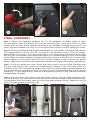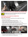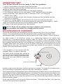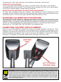
1
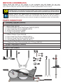
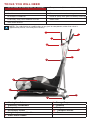
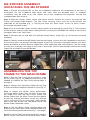
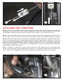
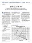
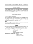
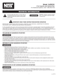
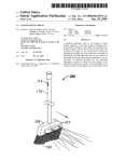
USER MANUAL BEFORE ASSEMBLING Always follow the steps in this manual as you assemble your M5 Strider. Do not skip, substitute or modify any steps or procedures of this assembly, as doing so could result in personal injury and will void your warranty. We have put a number of precautions in this manual. WARNING: This symbol appearing throughout this manual means PAY ATTENTION! BE ALERT! When you see this warning symbol, your safety is involved. It is being used to call attention to POTENTIAL hazards that could result in personal injury or loss of life. NOTE: Informs you about things we recommend you do or are aware of, before performing the assembly. These notes are placed in the manual to aid you during a certain procedure or to make you aware of any general mandatory actions or information. PARTS INVENTORY A - Handlebar Assembly (560809) B - Handles (560810) C - Loose Parts Pack #1 1. 8 Socket Button Head Cap Screws (M8X12) (9515) 2. 2 Hex Head Cap Screws (M8x80) (9518) 3. 18 Small 5/16 Washers (9369) 4. 2 Large 5/16 Washers (9344) D - Loose Parts Pack #2 1. 8 Black Rubber Caps (565058) 2. 8 Hex Head Cap Screws (M8x10) (9514) 3. 2 Socket Head Cap Screws (M8x12) (9513) 4. 2 Hex Head Cap Screws (M8x16) (9511) E - Loose Parts Pack #3 1. 2 Aluminum Caps Preassembled with O-Rings (565005) F - Hanger Pedal Mounts (560906) G - Top Frame (560808) H - Main Frame (560807) C1 C2 C3 B A C3 C4 D1 F D3 D4 D2 E H Crank Arm Pedal Mounts Transport Wheel G TOOLS YOU WILL NEED You will need the following tools for assembly Torque wrench (Minimum 13 Nm / 10 ft-lb) One ratchet with 13mm socket 6mm Allen wrench One 13mm wrench Scissors or other safe cutting tool #2 Phillips screwdriver Paste or spray wax (post assembly cleaning) LPS Heavy Duty Rust Inhibitor w/straw Clean cloth 5mm Allen Wrench NOTE: The substitution or modification of any part or component, other than what is approved by Keiser, will void your warranty. 1 2 3 4 5 6 7 8 9 10 11 1 - Moving Handlebars 2 - Stationary Handlebars 3 - Computer 4 - Resistance Shifter 5 - Height Adjustment Handle 6 - Water Bottle Holder 7 - Storage Tray 8 - Flywheel 9 - Footpad 10 - Transport Wheels 11 - Base M5 STRIDER ASSEMBLY UNPACKING THE M5 STRIDER Step 1: Elevate the packed M5 so that the cardboard stapled to the underneath of the box is accessible. Pry the cardboard flaps down and away from the plywood base. A standard screwdriver may be used to pry the staples out of the cardboard and plywood. Discard the cardboard box after removal. Step 2: With the ratchet, 13mm socket and 13mm wrench, remove the screws securing the Top Frame and Hanger-Pedal Mounts. The Top Frame securing screw must be accessed from the underside of the plywood (Fig. 1). Raising the base will allow easier access to these screws. Discard the removed screws. Step 3: Cut all accessible straps and ties, being careful not to damage any parts (Fig. 2). Then remove the loose parts and set aside. When cutting the ties securing the Handlebar be careful to not cut the Computer Wire in the Top Frame. Step 4: Remove the nut and bolt that hold the Pedal Mount stable (Fig. 3). Discard the removed hardware. Step 5: Carefully remove the M5 Strider from the packaging. Lay out all of the components and check to assure all parts are present and undamaged. If parts are missing or damaged contact your local dealer, distributor or Keiser Service Department. After unpacking and verifying parts, you are ready to start your assembly. You need an area that is free of dirt, dust or other foreign material that could impair the assembly of your M5 Strider. 1 2 3 ASSEMBLING THE TOP FRAME TO THE MAIN FRAME Step 1: Rest the Top Frame (G) on the Main Frame (H) as shown (Fig. 4). An additional person may be needed to stabilize the Top Frame during Steps 2 through 5. Step 2: Connect the Computer Cable from the Top Frame to the Wire Coupler of the Main Frame (Fig. 5). Step 3: Rotate the Shifter Lever downwards. Insert the Shifter Cable from the Main Frame into the Cable Link from the Top Frame. Rotate the Shifter Cable from the Main Frame into the groove of the Link and pull the Barrel all the way into the recess of the Link (Fig. 6, next page). Look into the hole in the side of the Link, the Barrel end of the Shifter Cable should be visible. 4 Step 4: Pull the Shifter Cable Housing below the Bracket of the Top Frame. Insert the Metal Sleeve of the Cable Housing into the Bracket (Fig. 7, next page). Step 5: Insert the Top Frame into the Main Frame but do not secure. Be careful not to pinch either Cable. 5 6 7 ATTACHING THE COMPUTER Step 1: Remove the Computer from its packaging on the Top Frame, be careful not to damage the Computer or it’s wiring. With the #2 Phillips screwdriver remove the Computer Mounting Screw from the Handlebar Tube (located at the top of the Top Frame). Set this screw aside for later use. Step 2: Coil the Computer Cable into the Computer Mount Cavity (Fig. 8). Slide the Computer up into the two tabs (Fig. 9). Insert and secure the screw removed in Step 1 using the #2 Phillips screwdriver. Step 3: Follow this step to check your Shifter and Computer Cable Connections. Begin with the Shifter Lever in the down position. While holding the free end of both Pedal Mounts, rotate the Cranks one full turn or until the Computer turns on. The display will show “ODO” for 10 seconds, then cycle the Shifter forward and backward from “GEAR 1” through “GEAR 24” (Fig. 10, next page). If gears are displayed with no problems, the Computer is working properly. If Gears are not found check the Shifter and Computer Cable Connections. Step 4: Obtain the ratchet with 13mm socket, eight Hex Head Cap Screws (D2) and eight Small Washers (C4). Secure the Top Frame to the Main Frame (Fig. 11, next page). Torque the screws to 23 Nm (17 ft-lbs), then insert the Rubber Caps (D1) into the holes of the Main Frame (Fig. 12, next page). 8 9 10 12 11 FINAL ASSEMBLY Step 1: Obtain the Handlebar Assembly (A). Tilt the Handlebar Assembly slightly to place the two Socket Head Cap Screws (D3) into the mounting holes. Once each screw has been started, place the palm of one hand on the center of the Handlebar Assembly pressing firmly and evenly onto the Handlebar Post (Fig. 13). Use the 6mm Allen wrench to evenly tighten the screws. Step 2: Obtain the Handles (B) and Hanger-Pedal Mounts (F). The Handles and Hanger-Pedal Mounts are stamped either L or R (Fig. 14 & 15). Lay them on a flat horizontal surface. Orient the HangerPedal Mounts so that the L or R stamps face the L or R stamps inside the bracket of the Handles (Fig. 16). If the Handles and Hanger-Pedal Mounts are assembled correctly, the L and R should not be visible. Assemble handlebar to hanger pedal mount using 8 of PN 9515 with the 5mm Allen wrench, tighten 4 screws evenly. After all screws are tight, retighten screws to ensure they did not loosen. Follow the instructions in the supplied User Manual to assemble the remaining components. Step 3: Using the ratchet with 13mm socket and 13mm wrench, one Hex Head Cap Screw (D4) and one Large Washer (C5), secure the Handle/Hanger Assembly to the Top Frame. Place the Assembly on the Top Frame with the heads of the screws (installed in Step 2) pointing towards the user of the machine, and torque the screw to 23 Nm (17 ft-lbs). Insert the Aluminum Cap (E) into the Handle (Fig. 17, next page), being careful not to damage the attached O-Ring. Repeat for the other Handle/Hanger Assembly. Step 4: Use the ratchet with 13mm socket and 13mm wrench, one Hex Head Cap Screw (C2), two Small Washers (C4) and one Elastic Lock Nut (C3) to secure one Hanger to one Pedal Mount (Fig. 18, next page). Place one washer under the screw head and one before the nut. Torque the screw to 23 Nm (17 ft-lbs). Repeat for the other side. 13 14 15 16 17 18 THE M5 STRIDER SHOULD NOW BE FULLY ASSEMBLED, BUT ADDITIONAL STEPS ARE REQUIRED (APPLICATION OF LPS AND OPERATION CHECKLIST) BEFORE USING. WARNING: Perform the operations below before using to make sure the equipment is fully operational. Failing to test the equipment prior to normal use will void your warranty and could result in serious injury. CHECKING FOR PROPER OPERATION PRE-RIDE CHECKLIST Please inspect the Strider carefully and thoroughly before using. � All Parts Correctly Installed � Top to Main Frame Bolts Torqued to 23 Nm (17 ft-lbs) � Handle to Hanger-Pedal Mount Bolts Torqued to 23 Nm (17 ft-lbs) � Handle to Top Frame Bolts Torqued to 23 Nm (17 ft-lbs) � Hanger-Pedal Mount to Pedal Mount Bolts Torqued to 23 Nm (17 ft-lbs) � Apply LPS to Inside and Outside Hanger-Pedal Mount Bearings and Bolts (Fig. 19) � Apply LPS to each side of both Transport Wheel (J) Bearings (Fig. 20) � Apply LPS to Right Rear Bracket Bearing at the base of the Crank Arm (I) (Fig. 21) 19 � � � 20 21 Handlebar Adjustment Operates Properly Unit Has Been Polished With Paste or Spray Wax and a Clean Cloth Computer Installed, Calibrated and In Working Order OPERATION TEST Your Strider should now be ready to test its operation. 1. Adjust the Handlebar for proper height and comfort. 2. Move the Shifter downward for the least resistance, then move the Pedal nearest to you to the lowest position. 3. Step onto the Pedals, lowest Pedal first and begin pedaling. 4. The Computer should turn on and display “ODO” and total distance ridden across the bottom. After approximately 10 seconds “ODO” will change to “GEAR” and “TRIP”. 5. Now move the Shifter up and note the gear changing on the Computer and the resistance increasing. 6. Operate at various speeds and resistances to check for noise and vibration. 7. Slowly move the Shifter to full forward position to check that the emergency brake stops the Flywheel from turning and the display flashes “88:88”. 8. The test is complete, please enjoy your workout. NOTE: Since we are always striving to improve our products; our products are subject to change without notice. M5 RESISTANCE OVERVIEW The Keiser M5 Strider is a revolutionary new way to exercise, with a focus on Power Output. The understanding of the M5 resistance system can best be described in the explanation of eddy current resistance and the formula for Power: (Power = Force x Velocity). An eddy current is an electrical current in a conducting material that results from induction by a moving or varying magnetic field. On the M5, this is generated by the wheel passing through two opposing magnets. The flywheel (a conductor) passes through the magnetic field generated by the two powerful magnets. By varying how much of the magnetic field comes into contact with the flywheel, the amount of resistance will increase or decrease for the user. This resistance system also allows the participant a smoother, quieter, and more predictable workout. If the flywheel is in less contact with the magnetic field, it is easier to operate. Mor e ce tan Le s sR e anc ist Re Rotating Magnet Housing sis es The more of the flywheel that comes in contact with the magnetic field (the higher the energy that is being generated with each turn) the more difficult it becomes to operate. Cutaway Revealing Magnet Flywheel Another major factor that plays a role in resistance is speed. The faster the flywheel turns, the more energy is generated, and thus the more resistance is created. Power (amount of work being done in a given amount of time by the participant) = Force (the amount of resistance) x Velocity (the Cadence the user is striding). This is the same formula that occurs naturally. By moving faster the difficultly increases as the resistance increases. The same applies to the M5, at a set Gear the resistance can be increased or decreased by adjusting the participants speed. In this way the M5 is very similar to natural movement. The higher the Gear, the higher the Cadence the more Power produced. M5 COMPUTER OVERVIEW The M5 computer is a powerful teaching and programming tool. The computer can assist both the instructor and participant by providing immediate feedback as well as tracking on-going improvement. By experiencing objective Cadence, Power Output, Gears and Heart Rate, the participant benefits from a better overall and more effective workout. The computer can also be used as a motivating tool to engage participants in their workouts. The more participants understand the components of a proper workout, the further they can fine tune their performance. The goal is to work more effectively and efficiently, and achieve better results. LINE 1 BACKLIGHT SENSOR While the M Series Computer is awake, the Backlight Sensor automatically detects ambient light levels in the room and turns on the backlit display when needed. LINE 2 RPM (CADENCE) The RPM displays the rider’s Revolutions Per Minute on one crank arm. RPM is also known in the cardio world as Cadence and is roughly the speed at which the participant is striding. At above 140 RPM the computer will not read and the word “STOP” will appear to indicate that the participant is striding faster than he or she needs to be. LINE 3 POWER The Power Output is displayed in Watts (currently generating) and Kilocalories (total value for the workout). The computer toggles back and forth between Watts (displayed for eight seconds) and Kilocalories (displayed for two seconds) throughout the ride. Rated accuracy for Power is +5W for Power below 50W, and +10% for Power above 50W. LINE 4 HEART RATE If there is no Heart Rate signal, a steady heart symbol and a zero will be displayed. If a participant is wearing a Heart Rate strap, once the computer locks onto the signal, the heart symbol will blink and display the heart rate. Please note that the Heart Rate strap must be Polar™ compatible and coded. WARNING: Heart rate monitoring systems may be inaccurate. Over exercise may result in serious injury or death. If you feel faint stop exercising immediately. LINE 5 ELAPSED TIME The number shown reports the total time spent cycling and will reset to zero after 60 seconds of inactivity or if computer is reset using the gear shifter. LINE 6 GEAR Gears from 1 – 24 are displayed on the bottom left hand of the screen. LINE 7 ODOMETER/TRIP DISTANCE For the first eight seconds when the computer is first activated, the Odometer will display the total distance the cycle has been ridden. This feature is for service and maintenance purposes only. After eight seconds, the Odometer will display Trip Distance. AVERAGE CALCULATIONS To view averages: RPM (Cadence), Power, and Heart Rate at any point in the workout, stop pedaling for three seconds. This will flash your averages until you start moving again or until the computer goes to sleep after 60 seconds. RESETTING RIDE AVERAGES, ELAPSED TIME AND DISTANCE To reset your averages during the workout, stop pedaling for three seconds and the averages will start to flash, while they are flashing move the gear shifter from bottom to top two times quickly. This will reset your workout information back to zero. M SERIES CALIBRATION PROCEDURE The Keiser M3 and M5 computer calibration procedure has changed with the addition of the backlit display. The M3 and M5 are calibrated with a tool at the factory and there is no need to calibrate, unless a component associated with the resistance mechanism or computer require service. For more information visit: www.keiser.com/service, or contact the Keiser service department at 1-800-888-7009 | 559-256-8000 | [email protected]. COMPUTER BATTERY REPLACEMENT To test the computer batteries rotate the crank arm until the computer “wakes up”. If the battery is low, a “LO-BA” will display in the Odometer (ODO) display at the bottom of the computer. To replace the batteries unscrew the back of the computer housing and remove old AA batteries and replace with a set of two new AA batteries. If you have multiple machines, we suggest all computer batteries be changed at the same time. UNSCREW HERE LIFT TO REVEAL BATTERY AREA WARNING: Do not burn batteries. Do not place batteries in waste bins. Batteries must be disposed of by a Licensed Waste Collector. Battery leakage is extremely caustic and contact with bare skin should be avoided. In the event that battery leakage comes in contact with your skin, flush the area for 15 minutes with copious amounts of water and seek medical attention. Gloves, overalls, safety shoes and eye protectors must be used when handling leaking batteries. Follow manufacturer’s recommendations when handling and maintaining batteries. PREVENTIVE MAINTENANCE CHART Every Class Member thoroughly inspect each Strider (1) Member wipe off sweat (2) Weekly For The 1st Month Check and re-torque crank arms (3) Weekly Thoroughly inspect each Strider (4) Clean with warm water and soft towel (5) Check computer for low battery indication (6) Monthly Check and re-torque crank arms (3) Wax those areas most in contact with sweat (7) Lubricate adjustment handle threads (8) 1. Each member should thoroughly inspect each Strider to make sure it is in safe and proper working order. 2. Each member should wipe off their own sweat after each class with a soft towel (their towel) or cloth. 3. Check and re-torque the screw holding the crank arm to the axle. The torque for both is 35 ft-lbs (47Nm). 4. Thoroughly inspect each Strider to make sure it is in safe and proper working order. Pay particular attention to loose screws, nuts & bolts, crank arms, footpads, handlebars, adjustment handles, etc. 5. Clean with warm water and a soft cloth the parts of the Strider that are dirty or come in contact with sweat. Do not use household or industrial cleaners, because many of them are designed to clean, glass, tile, porcelain, and greasy or oily surfaces and can destroy the protective finish of the paint. If you need to use soap, use a mild dish washing soap followed by an automotive treatment such as Meguiar’s Quick Detailer Mist and Wipe. 6. Check batteries. IF YOU HAVE MULTIPLE MACHINES, WE SUGGEST ALL COMPUTER BATTERIES BE CHANGED AT THE SAME TIME (2 AA batteries per bike). See “Computer Battery Replacement” section for instruction. 7. It is not necessary to wax the entire machine monthly, but it is very important to wax those areas that come in contact with sweat and that are the most vulnerable to rust. Use an easily applied automotive treatment such as Meguiar’s Quick Detailer Mist and Wipe. Please note that failure to apply a coat of wax to high sweat areas at least once a month will decrease paint and frame life due to corrosion and will void the warranty. 8. Remove, clean, and lubricate the threads on the adjustment handle. Since both the threaded stud and the threaded nut are stainless steel it is very important to keep the threads lubricated with a heavy grease, preferably white or clear in color, such as Hydrotex MT-55 or Dow Corning 111. NOTICE Users, agents or anyone directing the use of this equipment shall determine the suitability of the product for its intended use, and said parties are specifically put on notice that they shall assume all risk and liability in connection herewith. KEISER M5 STRIDER WARRANTY TERMS The Keiser M5 Strider is warranted to the original purchaser, to be free from defects in materials and workmanship. NOT COVERED UNDER WARRANTY - Loss caused by accident, abuse, improper use or neglect. - Improper maintenance. - Improper assembly by the purchaser. - Failure to follow instructions as stated in any of the manuals provided with the Keiser M5 Strider. The warranty terms begin with the date of original delivery to be evidenced by appropriate shipping documents. Any alteration of the equipment so listed without express written consent of Keiser shall constitute a waiver by the buyer of this warranty. This warranty does not cover other brand name products distributed, but not manufactured by Keiser, which are subject to their respective manufacturers warranties. During the warranty period, warranted defects will be repaired at Keiser, Fresno California, or the defective part will be replaced, at the option of the manufacturer, without charge for either parts or labor to repair the defective part. This warranty does not cover the removal of the defective part and installation of the repaired part. All claims under the warranty must be in writing and authorization obtained from the manufacturer, Keiser, to return the defective parts for exchange. Defective parts must be returned to Keiser. The customer is responsible for all transportation costs on returned items to and from the point of manufacture. Users, agents, or anyone directing the use of said equipment shall determine the suitability of the product for its intended use, and said parties are specifically put on notice that they shall assume all risk and liability in connection herewith. The foregoing warranties are in lieu of and exclude all other warranties not expressly set forth herein, whether expressed or implied by operation of law or otherwise, including but not limited to any implied warranties of merchantability or fitness. Keiser shall in no event be liable for incidental or consequential losses, damages or expenses in connection with exercise products. Keiser’s liability hereunder is expressly limited to the replacement of parts not complying with this warranty or, at Keiser’s election, to the repayment of an amount equal to the purchase price of the parts in question. Keiser is not responsible for labor charges incurred in the replacement of defective parts. Keiser may, at its discretion, require the return of all defective parts. The customer is responsible for all transportation costs on warranted items to and from the point of manufacture. Replacement products are warranted for the balance of the original warranty period. All Keiser equipment sold by Keiser distributors, dealers, or salespeople must be registered for warranty purposes. The warranty registration form must be filed within seven days of the sale or installation. Keiser equipment exported out of the US or Canada will be void of warranty unless purchased directly through a Keiser international distributor or dealer in the country of installation, or direct from Keiser’s international division. If you experience any problems please contact our Service Department phone: 559.256-8000 | toll free: 1.800.888.7009 | email: [email protected] KEISER CORPORATION 2470 S. CHERRY AVE. FRESNO, CA. 93706 WWW.KEISER.COM 565509_A