1
®
Badger Meter Europa GmbH
ModMAG® M2000
M-Bus interface
User manual
August 2012
MID_M2000_BA_MB_02_1208
Contents
Page
1. Basic safety recommendation ..................................................................................... 1 2. Introduction ................................................................................................................... 1 3. Hardware ........................................................................................................................ 2 4. Electrical connection .................................................................................................... 2 5. M-Bus addressing ......................................................................................................... 3 5.1 Primary address ..................................................................................................... 3 5.2 Secondary address ................................................................................................ 3 5.3 M-Bus commands .................................................................................................. 3 5.4 Setting primary address ......................................................................................... 3 5.5 Changing baud rate ............................................................................................... 4 5.6 Changing M-Bus response telegram ..................................................................... 4 5.7 Write configuration area to flash ............................................................................ 5 5.8 Send ModBus® commands .................................................................................... 5 5.9 M-Bus REQ_UD2 answers .................................................................................... 6 5.9.1 M-Bus REQ_UD2 answer „All“................................................................. 7 5.9.2 M-Bus REQ_UD2 answer „Instantaneous“ .............................................. 7 5.9.3 M-Bus REQ_UD2 answers “Testing” ....................................................... 8 5.9.4 M-Bus REQ_UD2 answer “Calibration” ................................................... 9 5.9.5 M-Bus REQ_UD2 answer “Manufacturing” ............................................ 10 6.
Technical data ............................................................................................................. 11
7.
Return of goods for repair.......................................................................................... 12
MID_M2000_BA_MB_02_1208
Basic safety recommendation / Introduction
1.
Page 1/12
Basic safety recommendation
Please see “Basic safety recommendations” in installation and operation manual
ModMAG® M2000.
2.
Introduction
The ModMAG® M2000 M-Bus module is providing a EN13757 compatible M-Bus
interface to the Badger ModMAG® M2000 flow meter with the following features:
•
•
•
•
•
M-Bus primary and secondary address selection
The primary address is saved in a non-volatile memory
300, 2400 and 9600 baud communication speed
Automatic baud rate detection or manually programmable baud rate
Standard M-Bus serial communication parameters: 8 data bits, 1 parity even bit,
1 stop bit.
• LED for M-Bus communication green: Incoming M-Bus transmission
Red: Outgoing M-Bus transmission
• Five different M-Bus response telegrams with different meter values (according to
EN13757-3, chapter 4.22, table 2):
− All
− Instantaneous values
− Testing
− Calibration
− Manufacturing
• Meter data update from ModMAG® M2000 every second
• M-Bus wrapper command for ModBus® communication
MID_M2000_BA_MB_02_1208
Hardware / Electrical connection
3.
Page 2/12
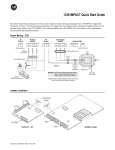
Hardware
L
N
PE
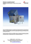
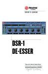
The additional M-Bus interface board is plugged in the communication socket (right
lower corner) of the ModMAG® M2000 main board. The interface board is supported by
a pad to the wall of the enclosure. A grounding strap connect the interface board
terminal 63 to the nearest screw of the main board.
JP1
CS
C2
C1
DISPLAY
JP2
8
9
10
11
12
13
14
15
16
E1
ES
E2
RS
EP
ES
COMMUNICATION
4.
BA2000-22MID
1
2
3
4
5
6
7
Electrical connection
Terminal
Description
63
Ground GND
62
M-Bus
61
M-Bus
MID_M2000_BA_MB_02_1208
M-Bus addressing
5.
Page 3/12
M-Bus addressing
5.1
Primary address
The module may be addressed using its primary address (range: 0...250). The
default (factory setting) primary address of the module is 0 (zero). The primary
address can be reconfigured using the appropriate M-Bus command (see below).
5.2
Secondary address
The module may be addressed using the secondary address selection scheme of
M-Bus. The secondary address consists of:
•
•
•
•
PCB serial number (8 digits BCD)
Manufacturer code (BMI, 0x09A9)
Generation (0x01)
Measured medium (0x07, cold water)
e.g.: 19100995,09A9,01,07
Any wildcard selection using the joker character ('F') is also possible:
19100995,FFFF,FF,FF
1910FFFF,FFFF,FF,FF
19100995,FFFF,FF,07
etc.
5.3
M-Bus commands
Since the device has got only two SND_UD commands, it is not possible to send
multiple commands within one M-Bus telegram.
5.4
Setting primary address
The default (factory setting) primary address of the module is 0 (zero). You may
program any other primary address in the range of 1 to 250 by using the standard
M-Bus SND_UD command for primary address setting:
Request (values in hex):
68 06 06 68 73/53 PAddr 51 01 7A NewAddr ChkS 16
Answer (values in hex):
E5
PAddr: Current primary address of the device
NewAddr: New primary address to program
Please note that the primary address is immediately written in the non-volatile
flash memory of the module. However, since the write cycles of the flash memory
are limited, the maximum number of write accesses are limited to 20 per 24
hours. If there are more write accesses within a 24 hours interval, the respective
primary address is kept in RAM and will automatically be written to the flash
memory in 24 hours time.
MID_M2000_BA_MB_02_1208
M-Bus addressing
5.5
Page 4/12
Changing baud rate
By default (factory setting) the module is automatically set to detect the baud rate
of the incoming M-Bus request telegram. Usually it is not necessary to change
this setting. However, if it is desired to set a fixed baud rate, you may use the
standard M-Bus commands to do so:
Request (values in hex):
68 03 03 68 73/53 PAddr
68 03 03 68 73/53 PAddr
68 03 03 68 73/53 PAddr
68 03 03 68 73/53 PAddr
B8
BB
BD
BF
ChkS
ChkS
ChkS
ChkS
16
16
16
16
set baud rate to 300 baud
set baud rate to 2400 baud
set baud rate to 9600 baud
set baud rate to auto baud
Answer to all of the above requests (values in hex):
E5
The acknowledged answer is always sent with the former baud rate. After having
sent the acknowledgement, the new baud rate becomes active.
Please note that the baud rate setting is not immediately written in the nonvolatile flash memory of the module but only:
• On the cyclic 24 hours reset
• Or if a set primary address command has been received and executed
• Or if the command to write the configuration area to flash has been
received and executed.
5.6 Changing M-Bus response telegram
The module may answer a M-Bus REQ_UD2 (request user data 2) telegram with one
of five different M-Bus RSP_UD (respond user data) telegrams, (according to
EN13757-3 chapter 4.22 table 2):
•
•
•
•
•
All
Instantaneous values
Testing
Calibration
Manufacturing
The telegram is selected by sending the appropriate M-Bus application reset telegram.
Request (values in hex):
68 03 03 68 73/53 PAddr
68 04 04 68 73/53 PAddr
68 04 04 68 73/53 PAddr
68 04 04 68 73/53 PAddr
68 04 04 68 73/53 PAddr
68 04 04 68 73/53 PAddr
50
50
50
50
50
50
ChkS 16 set "All" telegram
00 ChkS 16 set "All" telegram
50 ChkS 16 set "Instantaneous" telegram
90 ChkS 16 set "Testing" telegram
A0 ChkS 16 set "Calibration" telegram
B0 ChkS 16 set "Manufacturing" telegram
Answer to all of the above requests (values in hex):
E5
The next (and all the following) REQ_UD2 requests are then answered with the
selected telegram.
MID_M2000_BA_MB_02_1208
M-Bus addressing
Page 5/12
Please note that the RSP_UD telegram setting is not written immediately in the nonvolatile flash memory of the module but only:
•
•
•
On the cyclic 24 hours reset
Or if a set primary address command has been received and executed
Or if the command to write the configuration area to flash has been received
and executed.
5.7 Write configuration area to flash
The module has got a configuration area which holds settings for e.g. the baud rate
option, the primary address, the selected answer telegram etc. These settings are kept
in volatile RAM memory unless they are written in the non-volatile flash memory.
However, since the write cycles of the non-volatile flash memory are limited, the
respective RAM configuration values are only copied to the flash configuration values
every 24 hours (exception: the primary address). If the user wants to save the
configuration immediately in the non-volatile memory, he may execute the command
below:
Request (values in hex):
68 06 06 68 73/53 PAddr 51 00 FE 00 ChkS 16
save configuration to flash
Answer (values in hex):
E5
Please note that writing to the configuration area is under any circumstances limited to
20 times per 24 hours. Even with the above mentioned command it is not possible to
write more often.
5.8 Send ModBus® commands
Since not all of the ModBus® registers of the ModMAG® M2000 are retrievable using
"native" M-Bus commands, it is also possible to encapsulate "native" ModBus®
commands within a M-Bus command. It is then possible to use all the ModBus®
commands understood by the ModMAG® M2000 (0x03, 0x04, 0x06 and 0x10, register
reading and writing) with a M-Bus interface too.
Request (values in hex):
68 LL LL 68 73/53 PAddr 51 0F [ModBus] ChkS 16
send ModBus® command
LL: Length byte of M-Bus telegram
[ModBus]: ModBus® command without CRC
e.g.:
68 0A 0A 68 73/53 PAddr 51 0F 01 03 00 43 00 05 ChkS 16
The underlined part is the ModBus® command for reading the address 0x0043 (5
registers) of the ModMAG® M2000.
MID_M2000_BA_MB_02_1208
M-Bus addressing
Page 6/12
Answer (values in hex):
68 LL LL 68 08 PAddr 72 SecAddr AccessCtr Status Signature
0F [ModBus] ChkS 16
e.g.:
68 1D 1D 68 08 00 72 95 09 10
19 A9 09 01 07 08 01 00 00 Header for M-Bus RSP_UD
0F Flag: manufacturer specific
01 03 0A 31 39 31 30 30 39 39 35 00 00 ModBus® answer
ChkS 16
Please note however, that in case of using the encapsulated ModBus® commands, the
M-Bus communication timeout should be increased (e.g. from 50 ms to 400 ms), since
the requested registers are directly read and the results are returned within the answer
to the request.
Please note also that these commands are compatible with M-Bus physical and link
layers, but not completely compatible with the application layer. Therefore, all standard
M-Bus communication lines will transmit the command, however, the software on the
application side must be able to understand and interpret the command.
5.9 M-Bus REQ_UD2 answers
As mentioned before, the module may answer a REQ_UD2 data request by five
different RSP_UD answers according to its configuration:
All:
Contains the volumes, flow rate, flow speed, flow direction, etc.
Instantaneous:
Contains a short form of "All" with only the volumes, flow rate
and flow direction (smaller telegram = faster reading)
Testing:
Contains the meter diagnostic counters of the ModMAG®
M2000
Calibration:
Contains the meter calibration registers of the ModMAG®
M2000
Manufacturing:
Contains the product identification registers of the ModMAG®
M2000
Please note, that the module may also answer with a "busy" telegram in case the
answer telegram has been changed by the user and not all of the new data values
have been received from the ModMAG® M2000 yet. In this case the REQ_UD2
command must be repeated.
Request (values in hex):
10 7B/5B PAddr ChkS 16 REQ_UD2
Answer (values in hex):
68 04 04 68 08 PAddr 70 08 ChkS 16
CI =
0x70: Report of application errors
0x08: Application too busy for handling readout requests (see also,
EN13757-3, chapter 8.3)
MID_M2000_BA_MB_02_1208
M-Bus addressing
5.9.1
N° 0 1 2 3 4 5 6 7 8 9 Unit 0 1 2 0 1 0 0 0 0 0 Page 7/12
M-Bus REQ_UD2 answer „All“
Tariff 0 0 0 0 0 0 0 0 0 0 Storage 0 0 0 0 0 0 0 0 1 0 5.9.2
N°
0
1
2
3
4
Value 1.854350e‐003 0.000000e+000
1.854350e‐003 0 0 0.000000e+000
0.000000e+000
0.000000e+000
0.000000e+000
0 ModBus® register
0x00CF
0x00D7
0x00D7
0x00E7
0x00E8
0x00E9
0x00ED
0x00F3
0x00EB
0x012D
N°
0
1
2
3
4
5
6
7
8
9
N° 0 1 2 3 4 Data REAL4 REAL4 REAL4 INT2 INT2 REAL4 REAL4 REAL4 REAL4 INT2 Unit 0 1 2 0 0 Funct. Inst. Inst. Inst. Err. Err. Inst. Inst. Inst. Inst. Inst. VIB Volume [m3] Volume [m3] Volume [m3] No VIF No VIF m/s Volume Flow [1/sec] ‐>*10E3 No VIF Volume [m3] Control signal Description
T1 / T+ in m3
T2 / T- in m3
T3 / TN in m3
T1 / T+ Rollover counter
T2 / T- Rollover counter
Flow velocity in m/s
Flow rate in m3/s
Relative flow rate in %
Preset batch totalizer m3
Flow direction
M-Bus REQ_UD2 answer „Instantaneous“
Tariff 0 0 0 0 0 Storage 0 0 0 0 0 Data REAL4 REAL4 REAL4 REAL4 INT2 Value 1.854350e‐003 0.000000e+000
1.854350e‐003 0.000000e+000
0 ModBus® register
0x00CF
0x00D7
0x00D7
0x00E7
0x00E8
Funct. Inst. Inst. Inst. Inst. Inst. VIB Volume [m3] Volume [m3] Volume [m3] Volume Flow [1/sec] ‐>*10E3 Control signal Description
T1 / T+ in m3
T2 / T- in m3
T3 / TN in m3
Flow rate in m3/s
Flow direction
MID_M2000_BA_MB_02_1208
M-Bus addressing
5.9.3
N° 0 1 2 3 4 5 6 7 8 9 10 11 12 13 14 N°
0
1
2
3
4
5
6
7
8
9
10
11
12
13
14
Unit 0 0 0 0 0 0 0 0 0 0 0 0 0 0 0 Page 8/12
M-Bus REQ_UD2 answers “Testing”
Tariff 0 0 0 0 0 0 0 0 0 0 0 0 0 0 0 Storage 0 1 2 3 4 5 6 7 8 9 10 11 12 13 0 Data INT2 INT2 INT2 INT2 INT2 INT2 INT2 INT2 INT2 INT2 INT2 INT2 INT2 INT2 Value 40 41 0 0 0 0 0 1 2 16 20 0 0 1 2.083367e‐038 ModBus® register
0x00F5
0x00F6
0x00F7
0x00F8
0x00F9
0x00FC
0x00FD
0x00FE
0x00FF
0x0100
0x0101
0x0109
0x010A
0x0154
0x0107
Funct. Inst. Inst. Inst. Inst. Inst. Inst. Inst. Inst. Inst. Inst. Inst. Inst. Inst. Inst. Err VIB Commulation counter Commulation counter Commulation counter Commulation counter Commulation counter Commulation counter Commulation counter Commulation counter Commulation counter Commulation counter Commulation counter Commulation counter Commulation counter Commulation counter Storage interval [s] Description
Power up counter
Detector error counter
Empty pipe counter
Full scale counter
Totalizer overflow counter
Pulse sync counter
ADC interrupt counter
ADC range counter
WDT resets counter
WDT location
System error #
Action request overflows
Measurement overflows
Remote resets
Power loss totalizer in seconds
MID_M2000_BA_MB_02_1208
M-Bus addressing
5.9.4
N° 0 s1 e2 t3 4 s
5 c
r6 e7 w
8 s9 10 i
n11 12 Unit 0 0 0 0 0 0 0 0 0 0 0 0 0 Page 9/12
M-Bus REQ_UD2 answer “Calibration”
Tariff 0 0 0 0 0 0 0 0 0 0 0 0 0 Storage 0 1 2 3 2 3 4 5 0 1 0 1 6 Data INT2 INT2 REAL4 REAL4 REAL4 REAL4 REAL4 REAL4 REAL4 REAL4 INT2 INT2 REAL4 Value 9 50 0.000000e+000
0.000000e+000
0.000000e+000
0.000000e+000
7.692835e+008
1.000000e+000
2.003202e‐001 2.000000e‐001 0 2 0.000000e+000
N°
0
1
2
3
4
5
6
7
8
9
ModBus® register
0x006F
0x0070
0x0071
0x0073
0x0075
0x0077
0x0079
0x007B
0x007D
0x007F
10
11
12
0x0081
0x0082
0x010B
Funct. Inst. Inst. Inst. Inst. Inst. Inst. Inst. Inst. Inst. Inst. Inst. Inst. Inst. VIB mm mm No VIF No VIF m/s m/s No VIF No VIF Current [mA] Current [mA] Hs Hs No VIF Description
Detector diameter in mm
Detector diameter other in mm
Detector factor
[FACTORY] Detector factor
Detector offset in m/s
[FACTORY] Detector offset in m/s
Amplifier factor
[FACTORY] Amplifier factor
Detector current in mA
[FACTORY] Detector current in
mA
Power line frequency in Hz
Excitation frequency in Hz
Scale factor in %
MID_M2000_BA_MB_02_1208
M-Bus addressing
5.9.5
N° 0 1 2 3 4 5 6 7 8 9 10 11 12 13 N°
0
1
2
3
4
5
6
7
8
9
10
11
12
13
Unit 0 0 0 0 0 0 0 0 0 0 1 1 1 0 Page 10/12
M-Bus REQ_UD2 answer “Manufacturing”
Tariff
0 0 0 0 0 0 0 0 0 0 0 0 0 0 Storage 0 0 1 0 0 1 2 3 0 0 0 0 1 0 Data INT2 Var. Var. Var. Var. Var. Var. Var. Var. Var. INT2 INT2 INT2 INT2 Value 1 M2000 M2000 TMS320F2811 N‐Series v1.09 Sep 1 2010 09:32:43 BEFF D8D5 v1. 001 v1.09 3 1 0 258 ModBus® register
0x0000
0x0001
0x0009
0x0019
0x0023
0x0033
0x0048
0x004B
0x004E
0x0053
0x0057
0x0058
0x0059
0x011C
Funct.
Inst. Inst. Inst. Inst. Inst. Inst. Inst. Inst. Inst. Inst. Inst. Inst. Inst. Inst. VIB Model / Version Model / Version Model / Version Software version # No VIF No VIF No VIF No VIF Hardware version # Firmware version # Model / version Firmware version # Firmware version # Password Description
Product code
Product name
Firmware name
Application version
Compile date [MMM:DD:YYYY]
Compile time [HH:MM:SS]
OTP boot checksum
Flash OS checksum
Boot version
OS version
Daugtherboard product type
Daugtherboard major version
Daugtherboard minor version
Security status
MID_M2000_BA_MB_02_1208
Technical data
6.
Page 11/12
Technical data
The ModMAG® M-Bus module is providing a EN13757 compatible M-Bus interface to
the Badger ModMAG® M2000 flow meter
Product
Power supply
Current
ModMAG® M2000
interface
M-Bus interface
Isolation
Module size
Operating temperature
Storage temperature
Humidity
Product life time
ModMAG® M2000 M-Bus module
2 x +5V from M2000 internal module interface
(+5 V digital, +5V field)
1 mA from +5V digital
10 mA frp, +5V field
2 wire ModBus® interface
9600, 19200, 38400 baud auto-baud detection at firmware
start
8 data bits,
1 stop bit,
1 even parity bit
Phoenix IMC 1.5/11-G-3.81 connector to M2000
2 wire EN13757 compatible M-Bus interface
300, 2400, 9600 baud auto-baud detection
8 data bits
1 stop bit
1 even parity bit
1 M-Bus unit load (1.5 mA)
15 mA active M-Bus current
M-Bus input with reversible mains protection and protective
earth clamp
3 pin clamp
2500 V RMS isolation between M-Bus interface and
ModMAG® M2000
54 x 37 mm, maximum height 27 mm
-20 °C … +60 °C (-4 °F … +140 °F)
-40 °C … +70 °C (-40 °F … +160 °F)
90 %
˃ 10 years
MID_M2000_BA_MB_02_1208
Return of goods for repair
7.
Page 12/12
Return of goods for repair
Please copy, fill in and sign hereafter harmlessness declaration and enclose it for any
return of goods you may send back for repair.
No repair will be performed prior to receiving the harmlessness declaration duly filled
and signed.
Harmlessness declaration
To :
Attn.
:
From
:
Dept.
:
Please note that no repair will be performed prior to receiving of this declaration duly
signed by you!
Please send all parts clean from medium and inform us about possible medium wastes
remaining in the part. For this purpose, please use this form. A security specification
sheet of the medium must accompany this declaration in the following cases: Toxical,
dangerous or objectionable media, or media belonging to any dangerous materials
class. We inform you that uncleaned parts lead to additional costs. Extra clean costs
will be charged to you.
Declaration
We herewith confirm that the part(s) sent for repair has/have been cleaned and is/are
free of any liquid and/or solid wastes of the medium and/or cleaning medium: Any
eventually remaining wastes are:
harmless
dangerous, toxic, etc. – Security specifications are attached
Signature of person in charge:
Name of the person in charge in capital letters:
Date:
Company stamp:
MID_M2000_BA_MB_02_1208
Relais
3 1
0/4…20mA
250
0/2…10mA
geschlo
Normal
offen
Stromausg
Vorwärts
Frequenza
48
Relais
VmA
RelaisDurch
2
Durchflußrichtung
rückw
Durchflußrichtung
ang
(aktiv)rückw
usgang
500 mA
(passiv)
tsRelais
1
Skalenendwert
Hotline
Phone
+49-7025-9208-0 or -31
Fax
+49-7025-9208-15
®
Badger Meter Europa GmbH
Subsidiary of Badger Meter, Inc., USA
Nürtinger Strasse 76
72639 Neuffen (Germany)
E-mail: [email protected]
www.badgermeter.de