1
Outdoor 802.11n
Wireless Access Point
(P/N DA2131-V1)
Owner’s Manual
1308197 Rev. B
-i-
Federal Communications Commission Statement
This device complies with Part 15 of the FCC Rules and RSS-210 Issue 8 of Canada. Operation is
subject to the following two conditions:
•
This device may not cause harmful interference, and
•
This device must accept any interference received, including interference that may cause
undesired operation.
This equipment has been tested and found to comply with the limits for a class B digital device,
pursuant to Part 15 of the Federal Communications Commission (FCC) rules. These limits are
designed to provide reasonable protection against harmful interference in a residential installation.
This equipment generates, uses, and can radiate radio frequency energy and, if not installed and used
in accordance with the instructions, may cause harmful interference to radio communications.
However, there is no guarantee that interference will not occur in a particular installation. If this
equipment does cause harmful interference to radio or television reception, which can be determined
by turning the equipment off and on, the user is encouraged to try to correct the interference by one or
more of the following measures:
•
Reorient or relocate the receiving antenna.
•
Increase the separation between the equipment and receiver.
•
Connect the equipment into an outlet on a circuit different from that to which the receiver is
connected.
•
Consult the dealer or an experienced radio/TV technician for help.
Reprinted from the Code of Federal Regulations #47, part 15.193, 1993. Washington DC: Office of the Federal Register,
National Archives and Records Administration, U.S. Government Printing Office.
Canadian Department of Communications
This digital apparatus does not exceed the Class B limits for radio noise emissions from digital
apparatus set out in the Radio Interference Regulations of the Canadian Department of
Communications.
This Class B digital apparatus complies with Canadian ICES-003. Cet appareil numérique de la classe
B est conforme à la norme NMB-003 du Canada.
FCC Radio Frequency Exposure Caution Statement
In order to maintain compliance with the FCC RF exposure guidelines, this equipment should be
installed and operated with minimum distance 20cm between the radiator and your body. Use only
with supplied antenna. Unauthorized antenna, modification, or attachments could damage the
transmitter and may violate FCC regulations. Any changes of modifications not expressly approved by
the grantee of this device could void the users authority to operate the equipment.
Installation and use of this Wireless LAN device must be in strict accordance with the instructions
included in the user documentation provided with the product. Any changes or modifications (including
the antennas) made to this device that are not expressly approved by the manufacturer may void the
- ii -
user’s authority to operate the equipment. The manufacturer is not responsible for any radio or
television interference caused by unauthorized modification of this device, or the substitution or
attachment of connecting cables and equipment other than manufacturer specified. It is the
responsibility of the user to correct any interference caused by such unauthorized modification,
substitution or attachment. Manufacturer and its authorized resellers or distributors will assume no
liability for any damage or violation of government regulations arising from failing to comply with these
guidelines.
This device and its antenna(s) must not be co-located or operating in conjunction with any
other antenna or transmitter.
Declaration of Conformity (R&TTE directive 1999/5/EC)
The following items were completed and are considered relevant and sufficient:
•
Essential requirements as in [Article 3]
•
Protection requirements for health and safety as in [Article 3.1a]
•
Testing for electric safety according to [EN 60950]
•
Protection requirements for electromagnetic compatibility in [Article 3.1b]
•
Testing for electromagnetic compatibility in [EN 301 489-1] & [EN 301]
•
Testing according to [489-17]
•
Effective use of the radio spectrum as in [Article 3.2]
•
Testing for radio test suites according to [EN 300 328-2]
WARNING: TO PREVENT FIRE OR SHOCK HAZARD, DO NOT EXPOSE THIS PRODUCT TO
RAIN OR MOISTURE. THE UNIT MUST NOT BE EXPOSED TO DRIPPING OR SPLASHING
WATER.
CAUTION: DO NOT OPEN THE UNIT. DO NOT PERFORM ANY SERVICING OTHER THAN THAT
CONTAINED IN THE INSTALLATION AND TROUBLESHOOTING INSTRUCTIONS. REFER ALL
SERVICING TO QUALIFIED SERVICE PERSONNEL.
CAUTION: THIS DEVICE MUST BE INSTALLED AND USED IN STRICT ACCORDANCE WITH
THE MANUFACTURER’S INSTRUCTIONS AS DESCRIBED IN THE USER DOCUMENTATION
THAT COMES WITH THE PRODUCT.
WARNING: POSTPONE INSTALLATION UNTIL THERE IS NO RISK OF THUNDERSTORM OR
LIGHTNING ACTIVITY IN THE AREA.
When using this device, basic safety precautions should always be followed to reduce the risk of fire,
electric shock and injury to persons, including the following:
• Read all of the instructions {listed here and/or in the user manual} before you operate this
equipment.
• Give particular attention to all safety precautions.
- iii -
• Retain the instructions for future reference.
• Comply with all warning and caution statements in the instructions.
• Observe all warning and caution symbols that are affixed to this equipment.
• Comply with all instructions that accompany this equipment.
• Avoid using this product during an electrical storm. There may be a risk of electric shock from
lightning. For added protection for this product during a lightning storm, or when it is left
unattended and unused for long periods of time, unplug the power supply, and disconnect the Cat
5e to the N-WAP at the POE Injector. This will prevent damage to the product due to lightning and
power surges. It is recommended that the customer install an AC surge protector in the AC outlet
to which this device is connected. This is to avoid damaging the equipment by local lightning
strikes and other electrical surges. Operate this product only from the type of power source
indicated on the product’s marking label.
• If you are not sure of the type of power supplied to your home, consult your dealer or local power
company.
• Upon completion of any service or repairs to this product, ask the service technician to perform
safety checks to determine that the product is in safe operating condition.
Installation of this product must be in accordance with national wiring codes and conform to local
regulations.
Place POE Injector to allow for easy access when disconnecting the power cord/adapter of the device
from the AC wall outlet.
Wipe the unit with a clean, dry cloth. Never use cleaning fluid or similar chemicals. Do not spray
cleaners directly on the unit or use forced air to remove dust.
- iv -
TABLE OF CONTENTS
Chapter 1 Introduction ....................................................................................................................... 1 Overview ....................................................................................................................................... 1 Product Features .......................................................................................................................... 1 Package Content .......................................................................................................................... 1 Physical Details ............................................................................................................................ 2 Chapter 2 Physical Installation .......................................................................................................... 5 Physical Installation Steps .......................................................................................................... 5 Chapter 3 Network Settings ............................................................................................................. 10 Configuring and monitoring your DA2131-V1 from web browser .......................................... 10 Chapter 4 Basic System Settings .................................................................................................... 16 Setup Wizard............................................................................................................................... 16 DHCP ........................................................................................................................................... 16 Static ........................................................................................................................................... 17 PPPOE ......................................................................................................................................... 18 L2TP ............................................................................................................................................ 19 PPTP ............................................................................................................................................ 20 Configure Wireless Settings ...................................................................................................... 22 Operation Mode .......................................................................................................................... 23 Internet Settings ......................................................................................................................... 24 LAN Settings ............................................................................................................................... 26 VPN Passthrough ....................................................................................................................... 28 Advanced Wireless Settings ..................................................................................................... 31 Security ....................................................................................................................................... 33 WDS ............................................................................................................................................. 42 Status .......................................................................................................................................... 49 Firewall ........................................................................................................................................ 52 Port Forwarding.......................................................................................................................... 53 Administration ............................................................................................................................ 57 Firmware Update ........................................................................................................................ 58 Settings Management ................................................................................................................ 59 System Log ................................................................................................................................. 61 Appendix A DA2131-V1 Specifications ..................................................................................... 62 -v-
- vi -
Owner’s Manual of DA2131-V1
Chapter 1
Introduction
Overview
The DA2131-V1 Outdoor Wireless Access Point from Legrand now extends your home network’s
wireless reach to locations outside the home, such as patios or pool areas. With its environmental
protection, the DA2131-V1 can perform under rigorous weather conditions including heavy rain and
wind. With its Power over Ethernet (PoE) design, it can be easily installed in the areas where power
outlets are not available.
With built-in IEEE 802.11b/g/n wireless network capability, the Outdoor N-WAP allows any computer
and wireless enabled network client connect to it without additional cabling. With an 802.11n
compatible wireless adapter installed in your PC, the files can be transferred at speeds up to
150Mbps. The radio coverage is also designed specifically for outdoor use.
To secure the wireless communication, the Outdoor N-WAP supports the most up-to-date encryption:
64/128- bit WEP, WPA / WPA2, WPA-PSK / WPA2-PSK and 802.1x authority to secure and protect
your wireless LAN. MAC filtering and SSID broadcast control are provided to consolidate the wireless
network security and prevent unauthorized wireless connection.
The DA2131-V1 supports multiple modes, including AP/Client, WDS Bridge and WDS Repeater.
Product Features
IEEE 802.11b/g/n wireless standard compliant
10/100Mbps RJ-45 ports with auto MDI/MDI-X supported
Supports 64/128-bit WEP, WPA, WPA-PSK, WPA2, WPA2-PSK and 802.1x encryption
Package Content
The contents of your product package should include the following items:
DA2131-V1 802.11n Outdoor Wireless Access Point
POE Injector with reset button
Power Adaptor (12V, 1A)
Mounting Tie x 2
Installation/Instruction Sheet
A CD containing this manual.
-1-
Owner’s Manual of DA2131-V1
Physical Details
The following figures illustrate the physical details of the Outdoor N-WAP.
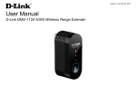
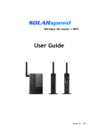
1.1 The Rear Panel – LED
Wireless LAN LED
Power LED
LAN Port LED
WAN Port LED
Figure 1-1 Rear Panel LED Identification
1.2 LED Indications
LED
Power
WLAN
WAN
LAN
State
Meaning
On
System On
Off
System Off
On
Wireless Radio ON.
Off
Wireless Radio Off.
Blinking
Data is transmitting or receiving on the wireless.
On
Port linked.
Off
No link.
Blinking
Data is transmitting or receiving on the WAN interface.
On
Port linked.
Off
No link.
Blinking
Data is transmitting or receiving on the LAN interface.
-2-
Owner’s Manual of DA2131-V1
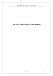
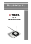
1.3 The Rear Panel – Port & Connector
RP-SMA Connector for External Antenna (not supplied)
WAN Port with PoE
LAN Port with PoE
Figure 1-2 Port and Connector of DA2131-V1
Figure 2-3 Port and Connector description label
Interface
Function
RP-SMA Connector
For external antenna. You can use the SMA connector to connect a 2.4GHz
external antenna (not supplied by Legrand).
The RJ-45 jack allows LAN connection through a Category 5 cable. Supports
LAN
auto-sensing on 10/100M speed and half/ full duplex; complys with IEEE
802.3/ 802.3u respectively.
The RJ-45 jack allows WAN connection through a Category 5 cable. Supports
WAN
auto-sensing on 10/100M speed and half/ full duplex; complys with IEEE
802.3/ 802.3u respectively.
1.
For External Antenna Mode, you MUST physically attach antenna before powering on.
2.
When using an external antenna, you should configure the Antenna Switch from
“Internal” to “External” via Web UI.
-3-
Owner’s Manual of DA2131-V1
1.4 PoE Injector
PoE Module
Figure 1-4 Top view of PoE Injector
3. Use only for DA2131-V1
Figure 1-5 Label of PoE Injector
PoE Reset Button
Reset Button
Figure 1.6 Reset Button of PoE Injector
Active
Time
Reset
Push and hold the reset button of POE injector about 5 ~ 10 seconds to
reset the configuration parameters to factory defaults.
-4-
Owner’s Manual of DA2131-V1
Chapter 2
Physical Installation
Physical Installation Steps
2.1 Preparation before Installation
2.1.1 Professional Installation Required
Please seek assistance from a professional installer who is well trained in Wireless data product installation and
knowledgeable in the local regulations.
2.1.2 Safety Precautions
1.
To keep you safe and install the hardware properly, please read and follow these safety precautions.
2.
If you are installing the DA2131-V1 for the first time, for your safety as well as others’, please seek
assistance from a professional installer who has received safety training on the hazards involved.
3.
Keep safety as well as performance in mind when selecting your installation site, especially where there
are electric power and phone lines.
4.
5.
When installing the DA2131-V1, please note the following things:
♦
Do not use a metal ladder;
♦
Do not work on a wet or windy day;
♦
Wear shoes with rubber soles and heels, rubber gloves, long sleeved shirt or jacket.
When the system is operational, avoid standing directly in front of it. Strong RF fields are present when
the transmitter is on.
2.1.3 Installation Precautions
To avoid damage to the DA2131-V1 while you are installing it, please read and follow these installation
precautions.
1.
Users MUST use a proper and well-installed surge arrestor with the DA2131-V1; otherwise, a random
lightening strike could easily cause fatal damage to the product. EMD (Lightning) DAMAGE IS NOT
COVERED UNDER WARRNTY.
2.
Users MUST use the “Power cord & PoE Injector” shipped in the box with the DA2131-V1. Use of
other options may cause damage to the product.
3.
Users MUST power off the DA2131-V1 first before connecting any external antenna to it. Do not
switch from built-in antenna to the external antenna from WEB management without physically attaching
the external antenna onto the device first; otherwise, damage might be caused to the DA2131-V1.
-5-
Owner’s Manual of DA2131-V1
2.2 Hardware Installation
2.2.1 Installation Steps
Step 1.
Push the latch in the bottom of DA2131-V1 to remove the sliding cover.
Figure 2-1 Move the cover
Step 2.
Plug the RJ-45 Ethernet cable into the LAN Port of DA2131-V1.
Figure 2-2 Cable Connection
RJ-45 8P8C Ethernet cable is required.
-6-
Owner’s Manual of DA2131-V1
Step 3.
Slide the cover back to seal the bottom of the DA2131-V1.
Figure 2-3 Seal the bottom
Step 4.
Take out the AC adapter and PoE injector, plug the power cord into the DC port and plug the other
side of the RJ-45 cable from STEP 2 into the POE port of the PoE injector.
DC: Insert adapter DC power cord
POE: This jack is connected to LAN port of the Outdoor N-WAP with the supplied Cat5 cable.
LAN: This jack is connected to LAN side PC/Hub or Router/ADSL modem device with a Cat5 cable
To DA2131-V1
Figure 2-4 Connect to PoE Injector
-7-
Owner’s Manual of DA2131-V1
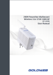
Step 5.
Complete the hardware installation as indicated on the illustration below.
Figure 2-5 Cabling complete
It will take about 50 seconds to complete the boot up sequence after powering on the
Outdoor N-WAP; Power LED will be active, and after that the WLAN Activity LED
will be flashing to show the WLAN interface is enabled and working now.
To avoid lightening strike damage, consider installing a lightening arrestor between the
NWAP and PoE injector.
-8-
Owner’s Manual of DA2131-V1
2.2.2 Pole Mounting
Step 1. Turn the DA2131-V1 over. Feed a pole mounting tie through the middle hole of the rear structure.
Step 2. Mount DA2131-V1 securely to the pole by fastening both mounting ties tightly.
Step 3. Now you have completed the hardware installation of DA2131-V1 as shown in the figure below.
Mounting Tie
Figure 2-6 Pole Mounting
2.2.3 Surface Mounting
Notice the rear bracket flange of the DA2131-V1 contains a screw hole in each corner for mounting to a flat surface
with appropriate screws (provided).
2.2.4 Using an External Antenna
If you prefer to use the external antenna with SMA-type connector for your application instead of the built-in
directional antenna, please follow the steps below.
Step 1. Connect your antenna with the SMA-type connector on the bottom of DA2132-V1.
Step 2. Power on the DA2131-V1, and then go to Wireless Settings-> Basic to configure the Antenna Switch
from “Internal” to “External”.
1.
2.
If you are going to use an external antenna on DA2131-V1, get some cable in advance.
Users MUST power off the DA2131-V1 first before connecting the external antenna to it.
Do not switch from built-in antenna to the external antenna from WEB management
without physically attaching the external antenna onto the DA2131-V1; otherwise,
damage might be caused to the Outdoor NWAP itself.
-9-
Owner’s Manual of DA2131-V1
Chapter 3
Network Settings
Configuring and monitoring your DA2131-V1 from a web browser
The DA2131-V1 integrates a web-based graphical user interface that can cover most configurations
and machine status monitoring. Via a standard web browser, you can configure and check machine
status from anywhere around the world.
NOTE: The DA2131-V1 comes from the factory with the following IP configuration:
Default IP Address: 192.168.40.252
Default IP Subnet Mask: 255.255.255.0
WEB login User Name; admin
WEB login Password: admin
3.1 Connecting to the Outdoor NWAP
For OS of Microsoft Windows 2000/ XP:
1.
Click the Start button and select Settings, then click Control Panel. The Control Panel window will
appear.
2.
Move mouse and double-click the right button on Network and Dial-up Connections icon. Move
mouse and double-click the Local Area Connection icon. The Local Area Connection window will
appear. Click Properties button in the Local Area Connection window.
Figure 3-1
3.
Check the installed list of Network Components. If TCP/IP is not installed, click the Add button to
install it; otherwise go to step 6.
- 10 -
Owner’s Manual of DA2131-V1
4.
Select Protocol in the Network Component Type dialog box and click Add button.
5.
Select TCP/IP in Microsoft of Select Network Protocol dialog box then click OK button to install the
TCP/IP protocol, it may need the Microsoft Windows CD to complete the installation. Close and go
back to Network dialog box after the TCP/IP installation.
6.
Select TCP/IP and click the properties button on the Network dialog box.
Figure 3-2
7.
Select Specify an IP address and type in values as following example.
IP Address: 192.168.40.2, or any IP address within 192.168.40.2 to 192.168.40.251 is good to connect
to the Outdoor NWAP.
IP Subnet Mask: 255.255.255.0
- 11 -
Owner’s Manual of DA2131-V1
40
2
Figure 3-3
8.
Click OK to complete the IP parameters setting.
For OS of Microsoft Windows Vista / 7:
1.
Click the Start button and select Settings, then click Control Panel. The Control Panel window will
appear.
2.
Move mouse and double-click the right button on Network Connections item. The Network
Connections window will appear. Double click Local Area Connection icon, then User Account
Control window shown. Right click Continue button to set properties.
3.
In Local Area Connection Properties window, Choose Networking tab, move mouse and click
Internet Protocol Version 4 (TCP/IPv4), then click Properties button.
- 12 -
Owner’s Manual of DA2131-V1
Figure 3-4
4.
Move mouse and click General tab, Select Specify an IP address and type in values as following
example.
IP Address: 192.168.40.2, or any IP address within 192.168.40.2 to 192.168.40.251 is good to connect
to the Outdoor NWAP. IP Subnet Mask: 255.255.255.0
40
Figure 3-5
- 13 -
2
Owner’s Manual of DA2131-V1
5.
Click OK to complete the IP parameters setting.
For OS of Microsoft Windows NT:
1.
Click the Start button and select Settings, then click Control Panel. The Control Panel window will
appear.
2.
Move mouse and double-click the right button on Network icon. The Network window will appear. Click
Protocol tab from the Network window.
3.
Check the installed list of Network Protocol window. If TCP/IP is not installed, click the Add button to
install it; otherwise go to step 6.
4.
Select Protocol in the Network Component Type dialog box and click Add button.
5.
Select TCP/IP in Microsoft of Select Network Protocol dialog box then click OK button to install the
TCP/IP protocol, it may need the Microsoft Windows CD to complete the installation. Close and go back
to Network dialog box after the TCP/IP installation.
6.
Select TCP/IP and click the properties button on the Network dialog box.
7.
Select Specify an IP address and type in values as following example.
IP Address: 192.168.40.2, or any IP address within 192.168.40.2 to 192.168.40.251 is good to connect to
the Outdoor NWAP.
IP Subnet Mask: 255.255.255.0
8.
Click OK to complete the IP parameters setting.
3.2 Web Login
Open a WEB browser, i.e. Microsoft Internet Explore 6.1 SP1 or above, then enter 192.168.40.252 on the URL
to connect the DA2131-V1.
DA2131-V1
40.252
Figure 3-6
After a moment, a login window will appear. Enter the User Name and Password. Then click the OK button.
- 14 -
Owner’s Manual of DA2131-V1
40.252
40.252
Figure 3-7 Login Window
Default User name: admin
Default Password: admin
If the above screen does not pop up, it may mean that your web-browser has been set to a
proxy. Go to Tools menu>Internet Options>Connections>LAN Settings, in the screen that
appears, cancel the Using Proxy checkbox, and click OK to finish it.
After you enter the username and password, the main screen appears as Figure 3-8
Figure 3-8 Web UI Screenshot
The next chapter will introduce the functions of the web UI.
- 15 -
Owner’s Manual of DA2131-V1
Chapter 4. Basic System Settings
Setup Wizard
This Setup Wizard page guides you to configure the Internet connection and Wireless Settings quickly.
Figure 4-1 Setup Wizard
Click Next button to next step for Internet connection settings. There are five options (DHCP, Static Mode,
PPPOE, L2TP, PPTP) for Internet connection on WAN port.
a. DHCP (Auto Config)
If your ISP provides the DHCP service, please choose Dynamic IP type, and the NWAP will automatically
obtain IP parameters from your ISP. You can see the page as follows
Figure 4-2 Step 1. DHCP
- 16 -
Owner’s Manual of DA2131-V1
The page includes the following fields:
Object
Host Name
Description
This option specifies the Host Name of the Router.
b. Static IP Address
If your ISP provides a static or fixed IP Address, Subnet Mask, Gateway and DNS setting, select
Static Mode (fixed IP). The Static IP settings page will appear, shown as following.
Figure 4-3 Step 1. Static Mode
The page includes the following fields:
Object
IP Address
Description
Enter the IP address in dotted-decimal notation provided by your ISP.
Subnet Mask
Enter the subnet Mask in dotted-decimal notation provided by your ISP,
usually is 255.255.255.0
Default Gateway
(Optional) Enter the gateway IP address in dotted-decimal notation provided
by your ISP.
Primary/Secondary DNS
(Optional) Enter one or two DNS addresses in dotted-decimal notation
provided by your ISP.
- 17 -
Owner’s Manual of DA2131-V1
c. PPPOE Connection
If your ISP provides a PPPoE connection, select PPPoE option. And enter the following parameters.
Figure 4-4 Step 1. PPPOE
The page includes the following fields:
Object
User Name/Password
Description
Enter the User Name and Password provided by your ISP. These fields are
case-sensitive.
Verify Password
Fill in the password again for verification.
Keep Alive: Keep the PPPoE connection all the time. Please also
configure the Redial Period field.
Operation Mode
On Demand: Please configure the Idle Time field. When time is
up, the PPPoE connection will disconnect. The connection will reconnect when any outgoing packet arise.
Manual: Let user connect the PPPoE connection manually.
Sometimes the connection cannot be terminated although you specify a time to Idle
Time, since some applications are visiting the Internet continually in the background.
- 18 -
Owner’s Manual of DA2131-V1
d. L2TP
If your ISP provides L2TP connection, please select L2TP option. And enter the following parameters.
Figure 4-5 Step 1. L2TP
The page includes the following fields:
Object
Description
L2TP Server IP Address
Allow user to make a tunnel with remote site directly to secure the
data transmission among the connection. User can use embedded
L2TP client supported by this router to make a VPN connection.
If you select the L2TP support on WAN interface, fill in the IP address
for it.
User Name/Password
Enter the User Name and Password provided by your ISP. These fields are
case-sensitive.
Address Mode
Static: To configure the IP address information by manually,
please fill in the related setting at below.
Dynamic: The option allows the machine to get IP address
information automatically from DHCP server on WAN side.
- 19 -
Owner’s Manual of DA2131-V1
IP Address
Fill in the IP address for WAN interface.
Subnet Mask
Fill in the subnet mask for WAN interface.
Default Gateway
Fill in the default gateway for WAN interface out going data packets.
Operation Mode
Keep Alive: Keep the L2TP connection all the time. Please also
configure the Redial Period field.
Manual: Let user connect the L2TP connection manually.
e. PPTP
If your ISP provides PPTP connection, please select PPTP option. And enter the following parameters.
Figure 4-6 Step1. PPTP
- 20 -
Owner’s Manual of DA2131-V1
The page includes the following fields:
Object
PPTP Server IP
Address
Description
Allow user to make a tunnel with remote site directly to secure the
data
transmission among the connection. User can use embedded PPTP
client supported by this router to make a VPN connection.
If you select the PPTP support on WAN interface, fill in the IP address
for it.
User Name/Password
Enter the User Name and Password provided by your ISP. These fields are
case-sensitive.
Address Mode
Static: To configure the IP address information by manually, please
fill
in the related setting at below.
Dynamic: The option allows the machine to get IP address
information automatically from DHCP server on WAN side.
IP Address
Fill in the IP address for WAN interface.
Subnet Mask
Fill in the subnet mask for WAN interface.
Default Gateway
Fill in the default gateway for WAN interface out going data packets.
Operation Mode
Keep Alive: Keep the PPTP connection all the time. Please also
configure the Redial Period field.
Manual: Let user connect the PPTP connection manually.
When you finish these settings, then click Next button to jump at Step2.
- 21 -
Owner’s Manual of DA2131-V1
Step 2: configure Wireless Settings
There are five options (Disable, OPENWEP, SHAREDWEP, WPA-PSK, WPA2-PSK) for Wireless security
connection.
Figure 4-7 Step 2. Configure Wireless Settings
Object
Network Mode
Description
This field determines the wireless mode which the NWAP works on.
This field determines which operating frequency will be used. The
Frequency (Channel)
default channel is set to AutoSelect, so the NWAP will choose the
best channel automatically. It is not necessary to change the wireless
channel unless you notice interference problems with another nearby
access point.
Enter a value of up to 32 characters. The same name of SSID
Network Name (SSID)
(Service Set Identification) must be assigned to all wireless devices in
your network. The default SSID is set to be Legrand WiFi. This value
is case-sensitive. For example, LEGRAND is NOT the same as
Legrand.
Channel Bandwidth
Security Mode
Select the operating channel width 20 MHz or 20/40 MHz.
Disable: No security required
OPENWEP / SHAREDWEP:
When you select WEP, please input 5, 13 (ASCII), 10 or 26
(HEX) characters for WEP Key.
WPA-PSK / WPA2-PSK: You can enter ASCII characters between 8
and 63 characters or 8 to 64 Hexadecimal characters.
When you finish these settings, then click Apply button to save.
- 22 -
Owner’s Manual of DA2131-V1
4.2 Operation Mode
Figure 4-8 Operation Mode Configurations
a. Bridge:
The Bridge mode allows that all Ethernet and wireless interfaces are bridged into a single Bridge interface.
b. Gateway:
The Gateway mode allows that the first Ethernet port is treated as WAN port and the Ethernet port and the
wireless interface are bridged together and are treated as LAN ports.
c. Wireless ISP:
The Wireless ISP mode allows that the wireless interface is treated as WAN port, and the Ethernet ports are
LAN ports.
- 23 -
Owner’s Manual of DA2131-V1
4.3 Internet Settings
4.3.1 WAN
Figure 4-9 WAN Settings
a. STATIC
Object
IP Address
Description
Enter the IP address in dotted-decimal notation provided by your ISP.
Subnet Mask
Enter the subnet Mask in dotted-decimal notation provided by your ISP,
usually is 255.255.255.0
Default Gateway
(Optional) Enter the gateway IP address in dotted-decimal notation provided
by your ISP.
Primary/Secondary DNS
(Optional) Enter one or two DNS addresses in dotted-decimal notation
provided by your ISP.
b. DHCP
Object
Host Name
Description
This option specifies the Host Name of the Router.
MAC Clone
Take NIC MAC address of PC on LAN side as the MAC address of WAN
interface.
- 24 -
Owner’s Manual of DA2131-V1
c. PPPoE
Object
User Name/Password
Description
Enter the User Name and Password provided by your ISP. These fields are
case-sensitive.
Verify Password
Fill in the password again for verification.
Keep Alive: Keep the PPPoE connection all the time. Please also
configure the Redial Period field.
Operation Mode
On Demand: Please configure the Idle Time field. When time is up,
the PPPoE connection will disconnect. The connection will re-connect
when any outgoing packet arise.
Manual: Let user connect the PPPoE connection manually.
d. L2TP
Object
L2TP Server IP Address
Description
Allow user to make a tunnel with remote site directly to secure the
data transmission among the connection. User can use embedded
L2TP client supported by this router to make a VPN connection.
If you select the L2TP support on WAN interface, fill in the IP address
for it.
User Name/Password
Enter the User Name and Password provided by your ISP. These fields are
case-sensitive.
Address Mode
Static: To configure the IP address information by manually,
please fill in the related setting at below.
Dynamic: The option allows the machine to get IP address
information automatically from DHCP server on WAN side.
IP Address
Subnet Mask
Default Gateway
Operation Mode
Fill in the IP address for WAN interface.
Fill in the subnet mask for WAN interface.
Fill in the default gateway for WAN interface out going data packets.
Keep Alive: Keep the L2TP connection all the time. Please also
configure the Redial Period field.
Manual: Let user connect the L2TP connection manually.
e. PPTP
Object
PPTP Server IP
Address
Description
Allow user to make a tunnel with remote site directly to secure the
data transmission among the connection. User can use embedded
PPTP client supported by this router to make a VPN connection.
- 25 -
Owner’s Manual of DA2131-V1
If you select the PPTP support on WAN interface, fill in the IP address
for it.
User Name/Password
Enter the User Name and Password provided by your ISP. These fields are
case-sensitive.
Address Mode
Static: To configure the IP address information by manually,
please fill in the related setting at below.
Dynamic: The option allows the machine to get IP address
information automatically from DHCP server on WAN side.
IP Address
Subnet Mask
Default Gateway
Operation Mode
Fill in the IP address for WAN interface.
Fill in the subnet mask for WAN interface.
Fill in the default gateway for WAN interface out going data packets.
Keep Alive: Keep the PPTP connection all the time. Please also
configure the Redial Period field.
Manual: Let user connect the PPTP connection manually.
4.3.2 LAN
Figure 4-10 LAN Settings
The page includes the following fields:
- 26 -
Owner’s Manual of DA2131-V1
Object
MAC Address
IP Address
Subnet Mask
Description
The physical address of the NWAP, as seen from the LAN. The value can't
be changed.
Enter the IP address of your NWAP or reset it in dotted-decimal notation
(factory default: 192.168.40.252).
An address code that determines the size of the network. Normally use
255.255.255.0 as the subnet mask.
Default Gateway
Fill in the default gateway for LAN interfaces out going data packets.
DHCP Type
Disable: Disable DHCP server on LAN side.
Server: Enable DHCP server on LAN side.
Start IP Address
End IP Address
Lease Time
802.1d Spanning Tree
LLTD
Fill in the start IP address to allocate a range of IP addresses; client with
DHCP function set will be assigned an IP address from the range.
Fill in the end IP address to allocate a range of IP addresses; client with
DHCP function set will be assigned an IP address from the range.
Fill in the lease time of DHCP server function.
Select enable or disable the IEEE 802.1d Spanning Tree function from pulldown menu.
Select enable or disable the Link Layer Topology Discover function from
pull-down menu.
IGMP Proxy
Select enable or disable the IGMP proxy function from pull-down menu.
UPNP
Select enable or disable the UPnP protocol from pull-down menu.
DNS Proxy
Select enable or disable the DNS Proxy function from pull-down menu.
- 27 -
Owner’s Manual of DA2131-V1
4.3.3 DHCP Clients
The “DHCP clients” page shows all the active DHCP clients. The table window shows the active clients with
their Hostname, MAC address, assigned IP address, and time expired information.
Figure 4-11 DHCP Clients
4.3.4 VPN Passthrough
Figure 4-12 VPN Passthrough
The page includes the following fields:
Object
L2TP Passthrough
Description
Select enable or disable the L2TP pass-through function from pulldown menu.
IPSec Passthrough
Select enable or disable the IPSec pass-through function from pull-down
menu.
PPTP Passthrough
Select enable or disable the PPTP pass-through function from pull-down
menu.
- 28 -
Owner’s Manual of DA2131-V1
4.4 Wireless
4.4.1 Basic
Figure 4-13 Basic Wireless Settings
The page includes the following fields:
Object
Wireless On/Off
Description
Click Wireless OFF button to turn off wireless RF radio.
Click Wireless ON button to turn on wireless RF radio.
Antenna Switch
Select Internal antenna or External antenna for using.
The default is using Internal antenna.
Wireless Mode
Click to select wireless mode from pull down menu.
SSID
It is the wireless network name. The SSID can be 32 bytes long.
User can use the default SSID or change it.
- 29 -
Owner’s Manual of DA2131-V1
Broadcast Network
Enable or disable the SSID broadcast function.
Name (SSID)
AP Isolation
Wireless network is similar to the virtual local area network. All of the
Wireless client devices can access each other completely.
When you enable this function, it will turn off connection between
wireless clients. Only allows connection between wireless client and
this AP router.
MBSSID AP Isolation
Enable this function will turn off connection between clients with different
MBSSID. Example: The client connected with BSSID 1. When enable this
function, it will not connect with BSSID 2. Only can access between clients
with SSID 1.
BSSID
Show the MAC address of Wireless interface.
Frequency (Channel)
Select the wireless communication frequency/channel from pull-down menu.
Operating Mode
Select “Mixed Mode” for 11b/g/n mode or “Green Field” for 11n mode.
Channel BandWidth
Select the operating channel width 20 MHz or 20/40 MHz.
Guard Interval
Select “Long” or “Auto”. Guard intervals are used to ensure that distinct
transmissions do not interfere with one another. Only effect under Mixed
Mode.
MCS
Select 0~7 or “Auto” from pull down menu. The default is “Auto”. Only
effect under Mixed Mode.
- 30 -
Owner’s Manual of DA2131-V1
4.4.2 Advanced
Figure 4-14 Advanced Wireless Settings
The page includes the following fields:
Object
B/G Protection Mode
Description
Default: Auto. You can select the other options including On and Off. The
B/G protection technology is CTS-To-Self. It will try to reserve the
throughput for 11g clients from 11b clients connecting to the device as AP
mode.
Beacon Interval
Beacons are the packets sending by Access point to synchronize the
wireless network. The beacon interval is the time interval between
beacons sending by this unit in AP or AP+WDS operation. The default
and recommended beacon interval is 100 milliseconds.
Data Beacon Rate(DTM)
This is the Delivery Traffic Indication Map. It is used to alert the clients
that multicast and broadcast packets buffered at the AP will be
transmitted immediately after the transmission of this beacon frame.
You can change the value from 1 to 255. The AP will check the
- 31 -
Owner’s Manual of DA2131-V1
buffered data according to this value. For example, selecting “1”
means to check the buffered data at every beacon.
Fragment Threshold
The fragmentation threshold determines the size at which packets are
fragmented (sent as several pieces instead of as one block). Use a low
setting in areas where communication is poor or where there is a great
deal of radio interference. This function will help you to improve the
network performance.
RTS Threshold
The RTS threshold determines the packet size at which the radio
issues a request to send (RTS) before sending the packet. A low RTS
Threshold setting can be useful in areas where many client devices are
associating with the device, or in areas where the clients are far apart
and can detect only the device and not each other. You can enter a
setting ranging from 0 to 2347 bytes.
TX Power
The default TX power is 100%. In case of shortening the distance and the
coverage of the wireless network, input a smaller value to reduce the radio
transmission power. For example, input 80 to apply 80% Tx power.
Short Preamble
Default: Disable. It is a performance parameter for 802.11 b/g mode and not
supported by some of very early stage of 802.11b station cards. If there is no
such kind of stations associated to this AP, you can enable this function.
Short Slot
It is used to shorten the communication time between this AP and station.
TX Burst
The device will try to send a serial of packages with single ACK reply from
the clients. Enable this function to apply it.
Country Code
Select the country code for wireless from pull down menu.
- 32 -
Owner’s Manual of DA2131-V1
4.4.3 Security
a. Disable
Figure 4-15 Wireless Security Settings
If you set Security Mode to “Disable”, the wireless data transmission will not include encryption to prevent
from unauthorized access and monitoring.
- 33 -
Owner’s Manual of DA2131-V1
b. OPEN-WEP
Figure 4-16 OPEN-WEP
If you set Security Mode to “OPEN-WEP” or “SHARED-WEP”, please fill in the related configurations at
below.
Object
Description
Default Key
Specify a Key number for effective.
WEP Keys
When you select the encryption type as WEP, please input 5, 13
(1~4)
(ASCII), 10 or 26 (HEX) characters for WEP Key.
- 34 -
Owner’s Manual of DA2131-V1
c. SHARED-WEP
Figure 4-17 SHARED-WEP
If you set Security Mode to “OPEN-WEP” or “SHARED-WEP”, please fill in the related configurations at
below.
Object
Description
Default Key
Specify a Key number for effective.
WEP Keys
When you select the encryption type as WEP, please input 5, 13
(1~4)
(ASCII), 10 or 26 (HEX) characters for WEP Key.
- 35 -
Owner’s Manual of DA2131-V1
d. WPA-RADIUS
Figure 4-18 WPA-RADIUS
The page includes the following fields:
Object
Description
WPA Cipher Suite
Select TKIP, AES or TKIPAES for WPA algorithms.
Key Renewal Interval
Please fill in a number for Group Key Renewal interval time.
IP Address
Enter the RADIUS Server’s IP Address provided by your ISP.
Port
Shared Secret
Enter the RADIUS Server’s port number provided by your ISP.
(The Default is 1812.)
Enter the password that the Wireless Router shares with the RADIUS Server.
Session timeout interval is for 802.1x re-authentication setting. Set to zero to
Session Timeout
disable 802.1x re-authentication service for each session. Session timeout
interval unit is second and must be larger than 60.
Idle Timeout
Enter the idle timeout in the column.
- 36 -
Owner’s Manual of DA2131-V1
e. WPA-PSK
Figure 4-19 WPA-PSK
The page includes the following fields:
Object
Description
WPA Cipher Suite
Select TKIP, AES or TKIPAES for WPA algorithms.
Pre-Shared Key
Please fill in a passphrase like ‘test wpa 123’, or a hexadecimal string
like '65E4 E123 456 E1'.
Key Renewal Interval
Please fill in a number for Group Key Renewal interval time.
- 37 -
Owner’s Manual of DA2131-V1
f. WPA2-RADIUS
Figure 4-20 WPA2-RADIUS
The page includes the following fields:
Object
Description
WPA Cipher Suite
Select TKIP, AES or TKIPAES for WPA algorithms.
Key Renewal Interval
Please fill in a number for Group Key Renewal interval time.
PMK Cache Period
Only valid in WPA2 security. Set WPA2 PMKID cache timeout period, after
time out, the cached key will be deleted. PMK Cache Period unit is minute.
Only valid in WPA2 security. The most important features beyond WPA to
Pre-Authentication
become standardized through 802.11i/WPA2 are: Pre-authentication, which
enables secure fast roaming without noticeable signal latency.
Shared Secret
Enter the password that the Wireless Router shares with the RADIUS Server.
- 38 -
Owner’s Manual of DA2131-V1
Session timeout interval is for 802.1x re-authentication setting. Set to zero to
Session Timeout
disable 802.1x re-authentication service for each session. Session timeout
interval unit is second and must be larger than 60.
IP Address
Enter the RADIUS Server’s IP Address provided by your ISP.
Port
Enter the RADIUS Server’s port number provided by your ISP. (The Default
is 1812.)
Shared Secret
Enter the password that the Wireless Router shares with the RADIUS
Server.
Session Timeout
Session timeout interval is for 802.1x re-authentication setting. Set to zero to
disable 802.1x re-authentication service for each session. Session timeout
interval unit is second and must be larger than 60.
Idle Timeout
Enter the idle timeout in the column.
g. WPA2-PSK
Figure 4-21 WPA2-PSK
The page includes the following fields:
Object
Description
WPA Cipher Suite
Select TKIP, AES or TKIPAES for WPA algorithms.
Pre-Shared Key
Please fill in a passphrase like ‘test wpa 123’, or a hexadecimal string
like '65E4 E123 456 E1'.
Key Renewal Interval
Please fill in a number for Group Key Renewal interval time.
- 39 -
Owner’s Manual of DA2131-V1
h. 802.1X
Figure 4-22 802.1X
The page includes the following fields:
Object
Description
WEP
Enable or Disable WEP encryption.
IP Address
Enter the RADIUS Server’s IP Address provided by your ISP.
Port
Enter the RADIUS Server’s port number provided by your ISP. (The Default
is 1812.)
Shared Secret
Enter the password that the Wireless Router shares with the RADIUS Server.
Session Timeout
Session timeout interval is for 802.1x re-authentication setting. Set to zero to
disable 802.1x re-authentication service for each session. Session timeout
interval unit is second and must be larger than 60.
Idle Timeout
Enter the idle timeout in the column.
- 40 -
Owner’s Manual of DA2131-V1
e. Access Policy
Figure 4-23 Access Policy
The page includes the following fields:
Object
Description
Policy
Select the Disabled, Allow or Reject of drop down menu choose wireless
access control mode. This is a security control function; only those clients
registered in the access control list can link to this NWAP.
Add a station MAC
Fill in the MAC address of client to register this AP router access
capability.
- 41 -
Owner’s Manual of DA2131-V1
5.4.4 WDS
In the Basic Wireless Settings page, select the Wireless Mode to “WDS” to setup the WDS connection.
a. WDS Mode
WDS mode allows user to operate as a standard WDS that forwards traffic between WDS links (links that
connect to other units in Repeater). The MAC addresses of WDS peers must be configured on the Wireless 11n
Access Points/ Repeaters. Basically this mode is used when you have a 2.4GHz outdoor router with more than
one WDS link to other AP/Repeaters.
Note: In this mode wireless clients will not be able to connect to the 2.4GHz outdoor router directly.
Step 1. In the Basic Wireless Settings, configure Wireless Mode to “WDS”.
Figure 4-24 Wireless Mode - WDS
- 42 -
Owner’s Manual of DA2131-V1
Step 2. Go to “Wireless Settings-> WDS”, fill in the MAC Address of the remote site.
Figure 4-25 WDS Configuration
1.
To Setup the WDS Connection, the channel must be the same in both sites. You should fix
the channel from “AutoSelect” to a static one.
2. You must fill in the MAC Address by each other. For example, enter the MAC Address of
the remote site to the settings of local site; and enter the MAC Address of the local site to
the settings of remote site.
3. The Encryption Type must be the same in both sites if available.
c. AP+WDS (Repeater) Mode
Repeater mode allows user to operate as a wireless repeater, extending the range for remote wireless clients and
connecting them to an AP connected to the wired network. The MAC addresses of WDS peers must be
configured on the Wireless 2.4G Access Point/Repeater.
- 43 -
Owner’s Manual of DA2131-V1
Step 1. In the Basic Wireless Settings, configure Wireless Mode to “AP+WDS”.
Figure 4-26 Wireless Mode – AP+WDS
- 44 -
Owner’s Manual of DA2131-V1
Step 3. Go to “Wireless Settings-> WDS”, fill in the MAC Address of the remote site.
Figure 4-27 WDS Configuration
1.
To Setup the WDS Connection, the channel must be the same in both sites. You should fix
the channel from “AutoSelect” to a static one.
2.
You must fill in the MAC Address by each other. For example, enter the MAC Address of
the remote site to the settings of local site; and enter the MAC Address of the local site to
the settings of remote site.
3.
The Encryption Type must be the same in both sites if available.
- 45 -
Owner’s Manual of DA2131-V1
4.4.5 Site Survey
This page is used to view or configure other APs near yours.
To connect with other AP by site survey, you need to configure the DA2131-V1 as “AP Client” mode in the
Basic Wireless Settings page as following.
Step 1. Go to “Wireless Settings-> Basic”, select the Wireless Moe to “AP Client”,
Figure 4-28 Basic Wireless Settings
Step 2. Go to “Wireless Settings->Site Survey” to scan the AP. Select the AP that you choose to connect, and
then click “Next”.
- 46 -
Owner’s Manual of DA2131-V1
Figure 4-29 Site Survey - 1
The page includes the following fields:
Object
SSID
Description
It shows the SSID of AP.
BSSID
It shows BSSID of AP.
RSSI
It shows the signal strength of current AP.
Channel
It show the current channel of AP occupied.
Encrypt
It shows the encryption status.
Wireless Mode
It show the wireless mode of AP.
Step 3. If the AP has encryption setting, it will pop out a window for you filling the encryption setting. Please
fill up the code, in this case, the code was “1234567890”, and click “Apply” to connect with the AP.
- 47 -
Owner’s Manual of DA2131-V1
Figure 4-30 Site Survey - 2
- 48 -
Owner’s Manual of DA2131-V1
Step 4. After connected with AP, you can open “Status” page under Administrator to check link status.
Figure 4-31 AP Status
- 49 -
Owner’s Manual of DA2131-V1
4.4.6 WPS
This section will guide you to add a new wireless device quickly to an existing network by WPS (Wi-Fi
Protected Setup) function.
Step 1. Choose menu “WPS”, you will see the next screen.
Figure 4-32 WPS Setup
The page includes the following fields:
Object
WPS
Description
Select Enable or Disable the Wi-Fi Protected Setup function. Then click
Apply button to take effect function after change.
Step 2. To add a new device:
If the wireless adapter supports Wi-Fi Protected Setup (WPS), you can establish a wireless connection between
wireless adapter and Router using either Push Button Configuration (PBC) method or PIN method.
To build a successful connection by WPS, you should also do the corresponding configuration of
the new device for WPS function meanwhile.
I.
By Push Button Configuration (PBC)
If the wireless adapter supports Wi-Fi Protected Setup and the Push Button Configuration (PBC) method, you
can add it to the network by PBC with the following two methods.
- 50 -
Owner’s Manual of DA2131-V1
Step 1: Choose PBC, and click “Apply”.
Figure 4-33 WPS - PBC
Step 2: Press and hold the WPS Button equipped on the adapter directly for 2 or 3 seconds. Or you can click
the WPS button with the same function in the configuration utility of the adapter.
1) Step 1 & 2 should process within two minutes.
2) DA2131-V1 only supports PBC method.
Step 3: Wait for a while until the connection established to complete the WPS configuration.
- 51 -
Owner’s Manual of DA2131-V1
4.5 Firewall
4.5.1 MAC /IP /Port Filtering
Figure 4-37 MAC/IP/Port filtering
The page includes the following fields:
Object
Description
MAC/IP/Port Filtering
Select Enable or Disable the MAC/IP/Port Filtering function.
Source MAC address
Fill in the MAC address of source NIC, to restrict data transmission.
Dest IP Address
Fill in the IP address of destination, to restrict data transmission.
Source IP Address
Fill in the IP address of source, to restrict data transmission.
Protocol
Select the protocol that you want to restrict. There are four options:
None, TCP, UDP and ICMP.
Dest Port Range
Fill in the start-port and end-port number of destination, to restrict data
transmission.
Source Port Range
Fill in the start-port and end-port number of source, to restrict data
transmission.
- 52 -
Owner’s Manual of DA2131-V1
Action
Select Accept or Drop to specify the action of filtering policies.
Comment
Make a comment for the filtering policy.
Delete Selected
Click Delete Selected button to delete all that you selected.
Reset
Click Reset button to clear selected items.
4.5.2 Port Forwarding
Figure 4-38 Port Forwarding
The page includes the following fields:
Object
Description
Port Forwarding
Select Enable or Disable the Port Forwarding function.
IP Address
To forward data packets coming from WAN to a specific IP address
that hosted in local network behind the NAT firewall, fill in the IP
address.
Port Range
To forward data packets coming from WAN to a specific IP address
- 53 -
Owner’s Manual of DA2131-V1
that hosted in local network behind the NAT firewall, fill in the port
range.
Protocol
Specify protocol, TCP&UDP, TCP or UDP.
Comment
Make a comment for the port forwarding policy.
Delete Selected
Click Delete Selected button to delete all that you selected.
Reset
Click Reset button to clear selected items.
Virtual Server
Select Enable or Disable the Virtual Server function.
IP Address
To forward data packets coming from WAN to a specific IP address
that hosted in local network behind the NAT firewall, fill in the IP
address.
Public Port
To forward data packets coming from WAN to a specific IP address
that hosted in local network behind the NAT firewall, fill in the public
port.
Private Port
To forward data packets coming from WAN to a specific IP address
that hosted in local network behind the NAT firewall, fill in the private
port.
Protocol
Specify protocol, TCP&UDP, TCP or UDP.
Comment
Make a comment for the virtual server policy.
Delete Selected
Click Delete Selected button to delete all that you selected.
Reset
Click Reset button to clear selected items.
4.5.3 DMZ
Figure 4-39 DMZ
The page includes the following fields:
Object
DMZ Settings
DMZ IP Address
Description
Enable or Disable the DMZ function.
To support DMZ in your firewall design, fill in the IP address of DMZ
host that can be access from the WAN interface.
- 54 -
Owner’s Manual of DA2131-V1
4.5.4 System Security
Figure 5-40 System Security
The page includes the following fields:
Object
Description
Remote management
Select Deny or Allow for remote management function.
Ping form WAN Filter
Select Disable or Enable for Ping permit from WAN.
SPI Firewall
Select Disable or Enable for SPI firewall function.
- 55 -
Owner’s Manual of DA2131-V1
4.5.5 Content Filtering
Figure 4-41 Content Filtering
The page includes the following fields:
Object
Description
Keyword
Fill in a word for Webs Host Filter policy.
URL
Fill in a URL string for URL filter. Then click Add button to save the
URL filter policy or click Reset button to clear the field.
Delete
Click Delete button to delete all that you selected.
Reset
Click Reset button to clear selected items.
- 56 -
Owner’s Manual of DA2131-V1
4.6 Administrator
4.6.1 Management
Figure 4-42 System Management
The page includes the following fields:
- 57 -
Owner’s Manual of DA2131-V1
Object
Description
Username
Fill in the user name for web management login control.
Password
Fill in the password for web management login control.
Current Time
It shows the current time.
Time Zone
Select the time zone in your country from pull-down menu..
NTP Server
Fill in NTP server IP address.
NTP synchronization
Fill in a number to decide the synchronization frequency with NTP server.
Dynamic DNS Provider
Click the drop down menu to pick up the right DDNS provider you
registered.
Account
Fill in the account of DDNS you registered.
Password
Fill in the password of DDNS you registered.
DDNS
Fill in the domain name that you registered.
4.6.2 Upload Firmware
Figure 4-43Upload F/W
The page includes the following fields:
Object
Location
Description
Click the Browse button to select the new firmware image file on PC.
And click the Apply button to upgrade firmware.
- 58 -
Owner’s Manual of DA2131-V1
4.6.3 Settings Management
Figure 4-44 Setting Management
The page includes the following fields:
Object
Description
Export Button
Click Export button to export the current configuration to your PC.
Settings file location
Click Browse button to select the configuration file from your PC, then
click Import button to update the configuration.
Load Default Button
Click the Load Default button to reset the configuration parameter to
factory defaults.
- 59 -
Owner’s Manual of DA2131-V1
4.6.4 Status
This page shows the current status and some basic settings of the device, includes system info, Internet
Configurations and Local Network.
Figure 4-45 Status
- 60 -
Owner’s Manual of DA2131-V1
4.6.5 System Log
This page is used to view the system logs.
Figure 4-46 System Log
The page includes the following fields:
Object
Description
Refresh
Click the Refresh button to refresh the log shown on the screen.
Clear
Click the Clear button to clear the log display screen.
- 61 -
Owner’s Manual of DA2131-V1
Appendix A: Specifications
Product
DA2131-V1
150Mbps 802.11n Wireless Outdoor Access Point
Hardware Specification
IEEE802.11b/g
IEEE 802.11n
Standard support
IEEE 802.3 10Base-T
IEEE 802.3u 100Base-TX
IEEE 802.3x Flow Control
Chipset
Ralink RT3050
16 Mbytes DDR SDRAM
Memory
4 Mbytes Flash
Wireless IEEE802.11b/g/n
Interface
LAN: 1 x 10/100Base-TX, Auto-MDI/MDIX
WAN: 1 x 10/100Base-TX, Auto-MDI/MDIX
Internal (Default): 12dBi directional antenna (Vertical-Pol)
Horizontal: 60 degree
Vertical: 30 degree
Antenna
External (Option): RP-SMA type Connector
Switchable by Software
For External Antenna Mode, attach antenna before power on
Enclosure
IP55 waterproof case
Passive PoE / 12V DC
PoE
Reset Button on PoE Injector
LAN RJ-45 Pin Assignment: PIN 4(+), PIN 7,8(-), PIN 5(Reset)
Wireless Interface Specification
Frequency Band
2.4~2.4835GHz
Transmission/Emission Type: DSSS / OFDM
Modulation
Data modulation type: OFDM with BPSK, QPSK, 16-QAM, 64-QAM,
DBPSK, DQPSK, CCK
802.11b: 11, 5.5, 2 and 1 Mbps with auto-rate fall back
802.11g: 54, 48, 36, 24, 18, 12, 9 and 6Mbps
Data Rate
802.11n (20MHz): up to 72Mbps
802.11n (40MHz): up to 150Mbp
America/ FCC: 2.414~2.462GHz (11 Channels)
Opt. Channel
Europe/ ETSI: 2.412~2.472GHz (13 Channels)
Japan/ TELEC: 2.412~2.484GHz (14 Channels)
802.11b: 27 ± 1dBm
RF Output Power
802.11g: 26 ± 1dBm
802.11n: 22 ± 1dBm
IEEE 802.11b: -93dBm
Receiver Sensitivity
IEEE 802.11g: -91dBm
IEEE 802.11n: -812dBm
Media Access Control
CSMA/CA
Output Power Control
Range 1~100, default:100
Power Requirements
12V DC, 1A (switching)
Wireless Management Features
Wireless Mode
AP
- 62 -
Owner’s Manual of DA2131-V1
Channel Width
Encryption Security
Wireless Isolation
Wireless Security
B/G Protection Mode
Max. Wireless Client
Max. WDS AP
Software
LAN
WAN Protocol
VPN Passthrough
Client
WDS PtP
WDS PtMP
WDS Repeater (AP+WDS)
Universal Repeater (AP+Client)
20MHz / 40MHz
64/128-bits WEP
WPA, WPA-PSK
WPA2, WPA2-PSK
802.1X
Enable it to isolate each connected wireless clients, to let them cannot access
mutually.
Provide wireless LAN ACL (Access Control List) filtering
Wireless MAC address filtering
Support WPS (WIFI Protected Setup )
Enable/Disable SSID Broadcast
A protection mechanism prevents collisions among 802.11b/g modes
25
4
Built-in DHCP server supporting static IP address distributing
Support UPnP
Support IGMP Proxy, DNS Proxy
Support 802.1d STP - Spanning Tree Protocol
Static IP
DHCP (Dynamic IP)
PPPoE
PPTP
L2TP
PPTP
L2TP
IPSec
Firewall
Bridge
Gateway
Ethernet Converter (WISP)
NAT firewall with SPI (Stateful Packet Inspection)
Built-in NAT server supporting Port Forwarding (Virtual Server), and DMZ
Max. Wired Client
NTP
Management
Diagnostic tool
Built-in firewall with Port/ IP address/ MAC/ URL filtering
60
Network Time Management
Web UI, DHCP Client, Configuration Backup & Restore, Dynamic DNS
System Log
Environment & Certification
Operation Temp.
Storage Temp.
IP Level
Regulatory
Temp.: -20~70°c, Humidity: 10%~95% non-condensing
Temp.: -30~80°c, Humidity: 5%~95% non-condensing
IP65
CE / FCC / RoHS
Operating Mode
- 63 -