1
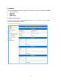
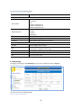
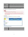
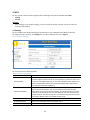
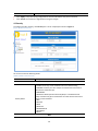
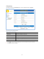
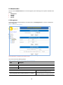
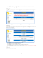
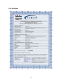
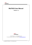
User’s Manual
Version 1.2
April 2013
Table of Contents
TABLE OF CONTENTS .................................................................................................................................... 2
1. INTRODUCTION ........................................................................................................................................ 4
1.1 Package Contents ..........................................................................................................................................4
1.2 Mobile Hot-Spot Interfaces ...........................................................................................................................4
1.3 Display Icons ..................................................................................................................................................5
1.4 Battery Time ..................................................................................................................................................5
1.5 Display Messages ..........................................................................................................................................5
1.6 Power Button LED Colors ..............................................................................................................................5
1.7 Technical Specifications ................................................................................................................................6
2. GETTING STARTED .................................................................................................................................... 7
2.1 Logging on to the Web-UI .............................................................................................................................7
2.2 Configuration Menu ......................................................................................................................................7
2.3 Overview .......................................................................................................................................................8
3. INTERNET ................................................................................................................................................. 9
3.1 Network Information.....................................................................................................................................9
3.2 LAN Settings ................................................................................................................................................10
3.3 Clients List ...................................................................................................................................................11
3.4 CDMA Settings .............................................................................................................................................12
4. WI-FI ...................................................................................................................................................... 13
4.1 Settings ........................................................................................................................................................13
4.2 Security ........................................................................................................................................................14
5. FIREWALL ............................................................................................................................................... 16
5.1 Port Forwarding...........................................................................................................................................16
5.2 Virtual Server ...............................................................................................................................................17
6. ADMINISTRATION................................................................................................................................... 18
6.1 Management ...............................................................................................................................................18
6.2 Upgrade .......................................................................................................................................................19
6.3 Settings ........................................................................................................................................................19
6.4 Manual ........................................................................................................................................................19
7. DEFAULT CONFIGURATION ..................................................................................................................... 20
7.1 Hostname ....................................................................................................................................................20
7.2 User IP Address ...........................................................................................................................................20
7.3 Web Server ..................................................................................................................................................20
7.4 Other Settings .............................................................................................................................................20
7.5 PPP Information ..........................................................................................................................................20
8. TROUBLESHOOTING ............................................................................................................................... 21
8.1 I forgot Login ID and Password / I forgot IP address after changing IP address ..........................................21
8.2 I cannot connect to the Internet .................................................................................................................21
9. CE CERTIFICATE .................................................................................................................................... 22
2
Preface
This manual describes the Web User Interface of the mobile hot-spot. This document provides a complete guide
to configure and use the mobile hot-spot.
Audience
Target audiences are the customers who configure and administer the mobile hot-spot. This manual makes it
easier for the customers to enhance the offerings or to customize the mobile hot-spot to their own services.
Typographic Conventions
This manual uses the following conventions.
[Table 1] Typographic Conventions
Item
Convention
Keys
Boldface
Field Names
Boldface
Screen Names
Boldface
Screen Elements
Boldface
Acronyms
This manual uses the following acronyms.
[Table 2] Acronyms
Acronym
Meaning
LAN
Local Area Network
IP
Internet Protocol
WAN
Wide Area Network
WWAN
Wireless Wide Area Network
SSID
Service Set Identifier
DNS
Domain Name Server
RSSI
Received Signal Strength Indicator
DRC
Data Rate Control
DHCP
Dynamic Host Configuration Protocol
BSSID
Basic Service Set Identifier
WPA
Wi-Fi Protected Access
WEP
Wired Equivalent Protocol
PPP
Point-to-Point Protocol
NAT
Network Address Translation
3
1. Introduction
1.1 Package Contents
•
•
•
•
•
Mobile Hot-Spot
Power Adapter
Car Charger
Quick Guide
Battery
1.2 Mobile Hot-Spot Interfaces
[E]
[A]
[F]
[B]
[G]
[H]
[C]
[D]
[I]
[A] Antenna: Sub antenna for diversity
[B] Display: OLED display for CDMA and hot-spot status icons and messages
[C] Power button: Power on/off by pressing for more than 3 seconds. Also a status indicator by 3-color LED
[D] Power adaptor connection: Connector for battery charging (Only use the USB cable and the 5.0-volt power
adaptor and car charger supplied in the package box)
[E] Antenna: Main Antenna
[F] External antenna connection: Connector for an external antenna for poor signal area
[G] Battery cover
[H] Battery: Removable battery (Li-Ion 2000mAh)
[I] Reset button: Push button to automatically power down the mobile hot-spot when pressed for more than 2
seconds and released. After re-powering on, the configuration is restored into the factory-default value
4
1.3 Display Icons
Icons
Description
Strength of the CDMA signal (levels 0 ~6)
Internet (data call) connection status
No service status
Wi-Fi on/off status
Battery level
Battery charging indicator while charging
1.4 Battery Time
Conditions
Description
Continuous use
3.5 hours while using in good signal status
Stand-by
8 hours
Charging
3.5 hours from empty to full charge with power off
5 hours with power on
1.5 Display Messages
Messages
Description
Net1
Operator name displayed while booting
Net1 M-90 1234
SSID displayed when entering into normal operation (“1234” is an example)
No Service
Displayed when mobile hot-spot could not find the CDMA network
12345678
Wi-Fi key displayed when user short-press the power button
(“12345678” is an example)
CONNECTING…
Displayed when mobile hot-spot is trying to make a data call
CONNECTED
Displayed when mobile hot-spot successfully made a data call
CONNECTION FAIL
Displayed when mobile hot-spot fails to make a data call
1.6 Power Button LED Colors
Color
Red
Blue
Purple
Mode
Status
Blinking
Low battery (below 10%)
Steady on
No service
Blinking
Trying to connect to the CDMA network
Steady on
Connected to the CDMA network and in service state
Blinking
Waking up from the power saving/Stand-by mode
Steady on
Power saving/Stand-by mode
5
1.7 Technical Specifications
Parameters
Specifications
Size
54.5 x 103.2 x 17.2mm
Weight
110g
Battery Type
3.7V Polymer
Operating Temperature
-20 to +70°C
Storage Temperature
-30 to +80°C
Humidity
85% Non-condensing
Stand-by Time
8 hours
Usage Time
3.5 hours
Adaptor Input
100 ~ 240VAC 50/60Hz 0.15A
Adaptor Output
5VDC 1A
6
2. Getting Started
This section explains how to configure the mobile hot-spot using the Web User Interface (Web-UI) provided. This
document assumes that you already have the mobile hot-spot and are now ready to do the configuration (i.e.,
power on, connected to the CDMA network, Wi-Fi on, etc.) You need to use the administrator right to configure
all the options available on the Web-UI.
First, you type in the following URL into the web browser on your client device connected to the mobile hot-spot.
http://192.168.0.1
2.1 Logging on to the Web-UI
To log on to the mobile hot-spot Web-UI, you must have a valid user name and password. The user name and the
password can be changed using Web-UI. When you log on to the mobile hot-spot Web-UI, the USER LOGIN window is displayed as shown in Figure 1.
[Figure 1] Web-UI Login window
•
•
•
Enter your User ID in the User text box. For an admin user, the default User ID is “admin”.
Enter your password in the Password text box. The default password is “admin”.
Click “OK” to begin the configuration or click “Cancel” to exit from this setup.
2.2 Configuration Menu
The Homepage is the first screen displayed when you log on to the mobile hot-spot Web-UI as shown in Figure 2.
Configuration Pages
The configuration menu for mobile hot-spot is show on the left side of the homepage.
It allows you to configure functions like Internet, Wi-Fi, etc. Each link is found under the top directory. The following modules are displayed in the left navigation pane.
•
Internet
•
Wi-Fi
•
Firewall
• Administration
7
2.3 Overview
The mobile hot-spot Web-UI is displayed as shown in Figure 2. The screen is refreshed every 30 seconds.
[Figure 2] Web-UI Homepage
The screen contains following details.
[Table 3] Fields in the Homepage
Field
Description
SYSTEM
Device Name
Current SSID of Wi-Fi interface
Battery Level
Current level of battery
Firmware Version
Current software version of mobile hot-spot
CDMA Version
Current CDMA Modem version
Modem ESN
Current CDMA Modem ESN(Electronic Serial Number)
INTERNET
Connection Status
Data call connection status
WAN IP Address
IP address of WWAN interface
Subnet Mask
Subnet mask of WWAN interface
Default Gateway
IP address of Gateway
Primary DNS
IP address of the Primary DNS server
Secondary DNS
IP address of the Secondary DNS server
LOCAL NETWORK
Local IP Address
Local IP address of LAN
MAC Address
Device hardware address
8
3. Internet
You can view Internet link in the left navigation pane. Followings are the options available under Internet.
•
Network Information
•
LAN Settings
•
Clients List
•
CDMA Settings
3.1 Network Information
To get information of Network, click Network Information link. A screen is displayed as shown in Figure 3.
The screen is refreshed every 15 seconds.
[Figure 3] Network Information
9
The screen contains the following details:
[Table 4] Fields in Network Information
Field
Description
Packet State
NETWORK
Service information can be:
• No Service
• 1X
• EVDO in network Rev. 0
• EVDO in network Rev. A
• EVDO in network Rev. B
Shows the service mode which can be:
• Hybrid
• 1X Only
• EVDO Only
Current packet state of modem
Carriers
Current count of assigned multi-carrier
Total DRC
Total network assigned data rate of carriers
Service Mode
Mode Preference
CARRIER [#]
Channel
EcIo
Current CDMA channel number
RSSI value (Unit: –dBm). The bigger the number is, the weaker the received signal is. 255(0xff) means no signal
Current signal level (Unit: dB)
PN
Pilot PN of current CDMA network cell
DRC
Data rate of each carrier
RSSI
3.2 LAN Settings
To configure LAN settings, click LAN Settings link. A screen is displayed as shown in Figure 4.
[Figure 4] LAN Settings
The screen contains the following details.
[Table 5] Fields in LAN Settings
10
Field
Description
IP Address
Current local IP address. If changed, you should reconnect mobile hot-spot.
Subnet Mask
Current subnet mask. You can change according to IP class.
MAC Address
Shows the mobile hot-spot hardware address.
DHCP IP Range
Current DHCP IP range. You can increase accessible user count.
DHCP Lease Time
Current DHCP lease time of allocated DHCP IP address.
• Click “Apply” at any time during configuration to save the information that you have entered.
• Click “Cancel” to exit from this page without saving the changes.
Caution:
•
•
If you have changed the local IP address of mobile hot-spot, you must input the new IP address in the
address field of your browser in order to access the Web-UI.
If the old and the new IP addresses of mobile hot-spot belong to different subnets (for example, if the
old address is 192.168.0.1 and the new address is 192.168.1.1), then IP addresses of computers connected mobile hot-spot will also change. In this case you should refresh the IP address of your computer in the Windows Network Connections, or simply disconnect your computer from mobile hot-spot
and then re-connect again.
3.3 Clients List
To view the Clients List, click Clients List link. A screen is displayed as shown in Figure 5.
[Figure 5] Clients List
The screen contains the following details.
[Table 6] Fields in Clients List
Field
Description
IP Address
IP address of Client
MAC Address
MAC Address of Client
11
3.4 CDMA Settings
To configure CDMA parameters, click CDMA Settings link. A screen is displayed as shown in Figure 6.
[Figure 6] CDMA Settings
The screen contains the following details:
[Table 7] Fields in CDMA Settings
•
•
Field
Description
Dial Number
Dial-Up number for CDMA data call
Username
Username for CDMA data call
Password
Password for CDMA data call
Click “Apply” at any time during configuration to save the information that you have entered.
Click “Cancel” to exit from this page without saving the changes.
12
4. Wi-Fi
You can view Wi-Fi link in the left navigation pane. Followings are the options available under WI-FI.
•
Settings
•
Security
Caution:
•
After changing any of the Wi-Fi settings, you must normally reconnect over Wi-Fi in order to access the
Internet and the Web-UI.
4.1 Settings
You can configure basic Wireless Settings for communication, such as Network Name (SSID) and Channel.
To configure the Wi-Fi interface, click Settings link. A screen is displayed as shown in Figure 7.
[Figure 7] Wireless Settings
The screen contains the following details.
[Table 8] Fields in Wi-Fi Settings
Field
BSSID
Description
Choose a mode from the pull-down menu. Make sure that you have the equipment that supports selected mode. As you’re looking for products in stores or on
the internet, you might notice that you can choose equipment that supports five
different combinations of Wi-Fi networking technologies: 802.11b/g/n Mixed,
802.11b/g Mixed, 802.11b and 802.11g.
Specify the network name. Each Wireless LAN network uses a unique Network
Name to identify the network. This name is called the Service Set Identifier
(SSID). When you set up your wireless adapter, you specify the SSID. If you want
to connect to an existing network, you must make up your own name and use it
on each computer. The name can be up to 17 characters long and contain letters
and numbers. Default name is the mobile hot-spot’s S/N.
MAC address of this wireless router.
Frequency(Channel)
Select 1~14 or AutoSelect from the pull-down menu.
Auto Selected Frequency
If AutoSelect is used, this field displays the current channel.
Network Mode
Network Name(SSID)
13
Rate
•
•
Specify the channel bandwidth.
Click “Apply” at any time during configuration to save the information that you have entered.
Click “Cancel” to exit from this page without saving the changes.
4.2 Security
To configure the Wi-Fi Security, click Security link. A screen is displayed as shown in Figure 8.
[Figure 8] Wireless Security
The screen contains the following details.
[Table 9] Fields in Wi-Fi Security
Field
Description
Security Mode
Net1 M-90 3893 (“3893” is an example)
Used to specify the WLAN security mode:
• Disable: No security mode. Disabled mode is the default setting.
• OPENWEP: Enables your client adapter to authenticate and communicate with the mobile hot-spot.
• SHAREDWEP
• WEPAUTO: Wired Equivalent Protocol (WEP) is a standardized and
widely used data encryption method that can make wireless networks as
secure as wired networks.
• WPA
• WPA-PSK
• WPA2
• WPA2-PSK
• WPAPSKPA2PSK
• WPA1WPA2
• 802.1X
WPA
14
WPA Algorithms
Select TKIP, AES, or TKIPAES
Pass Phrase
Input Pass Phrase (also called Password or Key)
Key Renewal Interval
Key Renewal Interval time
Policy
Add a station MAC Address:
•
•
ACCESS POLICY
Select “Disable” to de-activate the Access Policy; select “Allow” to allow
specific device(s) to connect to the mobile hot-spot; select “Reject” to
prevent specific device(s) from connecting to the mobile hot-spot.
Space to enter the MAC address of a device that is allowed to connect to
the mobile hot-spot. Multiple MAC addresses may be entered by clicking
the “Apply” button one after another.
Click “Apply” at any time during configuration to save the information that you have entered.
Click “Cancel” to undo any changes.
The following table shows the availability of various combinations of Wi-Fi security parameters depending
upon the authentication type and encryption type chosen.
[Table 10] Availability of Wireless Security Features
Authentication Type
Encryption Type
Key(s)
Radius Server Setup
WPA
Open Authentication
No encryption type
No
No
No
Open Authentication
WEP 64 (10 digits)
Yes
No
No
Open Authentication
WEP 128 (26 digits)
Yes
No
No
Shared Authentication
No encryption type
No
No
No
Shared Authentication
WEP 64 (10 digits)
Yes
No
No
Shared Authentication
WEP 128 (26 digits)
Yes
No
No
WPA-TLS
Standard 802.1X (WEP)
No
Yes
Yes
WPA-TLS
TKIP
No
Yes
Yes
WPA-TLS
AES-CCMP
No
Yes
Yes
WPA-PSK
TKIP
No
No
No
WPA-PSK
AES-CCMP
No
No
No
WPA2-TLS
AES-CCMP
No
Yes
Yes
WPA2-TLS
TKIP/AES-CCMP
No
Yes
Yes
WPA2-PSK
AES-CCMP
No
No
No
WPA2-PSK
TKIP/AES-CCMP
No
No
No
15
5. Firewall
You can view Firewall link on the left navigation pane. Following are the options available under Firewall.
•
Port Forwarding
•
Virtual Server
5.1 Port Forwarding
To configure Port Forwarding, click Port Forwarding link. A screen is displayed as shown in Figure 9:
[Figure 9] Port Forwarding
The screen contains the following details.
[Table 11] Fields in Port Forwarding
•
•
Field
Description
Forwarding
To enable or disable the port forwarding
IP Address
To enter the IP Address of a specified local machine
Port Range
To assign a range of port or specific port number to route the packets
Protocol
To assign protocol type of the packets
Comment
To add a comment
Click “Apply” at any time during configuration to save the information that you have entered.
Click “Reset” to undo any changes.
16
5.2 Virtual Server
To enable Virtual Server, click Virtual Server link. A screen is displayed as shown in Figure 10:
[Figure 10] Port Forwarding
The screen contains the following details.
[Table 12] Fields in Virtual Server
•
•
Field
Description
Virtual Server
To enable or disable the virtual server.
IP Address
To enter the IP Address of a specified local machine
Public Port
To assign a specific port number to route the packets
Private Port
To assign a user setting or specific port number to route the packets
Protocol
To assign protocol type of the packets
Comment
To add a comment
Click “Apply” at any time during configuration to save the information that you have entered.
Click “Reset” to undo any changes.
17
6. Administration
You can view the Administration link on the left navigation pane. Followings are the options available under
System.
•
Management
•
Upgrade
•
Settings
•
Manual
6.1 Management
To change user ID and the password for the administrator, click Management link. A screen is displayed as
shown in Figure 11.
[Figure 11] System Management
This menu does not add new user but makes user ID and the password change.
Only 1 administrator is available on the mobile hot-spot.
The screen contains the following details:
[Table 13] Fields in Administrator Settings and General Settings
Field
Description
ADMINISTRATION SETTINGS
Account
A new name which will be used to access the Web-UI
Password
A new password which will be used to access the Web-UI
GENERAL SETTINGS
Shut off LCD display after “2” minutes
Go to sleep mode when I’ve been inactive for “1” minutes
18
Time for automatic display shut off
Time for going into the sleep mode when
there are no devices connected over Wi-Fi
•
•
Click “Apply” at any time during configuration to save the information that you have entered.
Click “Cancel” to undo any changes.
6.2 Upgrade
To upgrade the system firmware, click on the Upgrade link. A screen is displayed as shown in Figure 12.
[Figure 12] Firmware Upgrade
•
After choosing a system firmware file, click “Apply” to start the firmware upgrade.
6.3 Settings
To update the system configuration or to get the current configuration, click Settings link. A screen is displayed as shown in Figure 13.
[Figure 13] Configuration Setting
•
•
•
•
Click “Export” to save the current configuration to a file.
Click “Import” to load configuration from a file.
Click “Browse” to select a specified file name to change the configuration.
Click “Load Default” to go back to factory default settings. In this case, you lose all your own settings.
6.4 Manual
The link to view this User’s Manual
19
7. Default Configuration
7.1 Hostname
SSID
Net1 M-90 1234
Security mode
Security mode
Password
12345678
See the OLED display or the label inside the battery cover
(“1234” is an example)
WPA2-PSK
Click button and see the Display LCD or label
(“12345678” is an example)
7.2 User IP Address
IP Address
192.168.0.100 — 192.168.1.109
Default Gateway
192.168.0.1
DNS Server
Network assigned DNS server
7.3 Web Server
IP Address
192.168.0.1
Username
admin
Password
admin
7.4 Other Settings
DHCP server
Enabled
NAT
Disabled
MODEM PPP
Automatically Started
Note: User can connect through Wi-Fi, get IP address, default gateway and DNS server address and can use
internet without any more configuration.
7.5 PPP Information
Access ID
cdma
Password
cdma
Authentication
chap-pap
Dial Number
#777
20
8. Troubleshooting
8.1 I forgot Login ID and Password / I forgot IP address after changing IP address
Use your mobile hot-spot after restoring the configuration into factory-default value.
How to restore the configuration?
•
Press “reset” button for more than 2 seconds and release in normal status.
•
User can see Power Button LED is blinking.
•
After about 15 seconds, mobile hot-spot is automatically turned off.
•
When re-powered on, you can see the configuration is changed to the factory-default value on Web-UI.
Caution: Please make sure mobile hot-spot has enough battery level when factory resetting is performed.
8.2 I cannot connect to the Internet
User should check the displayed icons and messages.
If Received Signal Strength Indicator icon (
) is not displayed, please refer to below Section 8.2.1.
Check whether Wi-Fi icon ( ) is displayed.
8.2.1 Check Wi-Fi
Check if the Wi-Fi icon ( ) is displayed.
If the Wi-Fi icon is on, connect to the mobile hot-spot by correct SSID. SSID value is different for each mobile
hot-spot to avoid interference. So, each mobile hot-spot has a unique SSID such as “Net1 M-90 1234”.
If Wi-Fi is connected, ping to mobile hot-spot’s LAN IP address (default: 192.168.0.1).
If ping is not OK, check if SSID is correct, and if Wi-Fi security is configured.
If ping is OK, refer to below Section 8.2.2.
8.2.2 Check CDMA
Check whether the Received Signal Strength Indicator icon (
) is displayed.
If Received Signal Strength Indicator icon is not displayed, check if the retractable antennas are fully pulled
out or check the status of PPP.
If WWAN (data call) connection status icon ( ) is displayed, PPP connection is established. If not, please
check other configurations on the Web-UI or network configuration of your client device.
21
9. CE Certificate
22
23