1
This manual describes the various matters concerning the
operations of GSK990MC system as much as possible. However, it is
impossible to give detailed descriptions to all the unnecessary or
unallowable operations due to space limitation and product specific
applications. Therefore, the matters not specially described herein
should be considered as “impossible” or “unallowable”.
This user manual is the property of
GSK CNC Equipment
Co., Ltd. All rights are reserved. It is illegal for any organization or
individual to publish or reprint this manual. GSK CNC Equipment Co.,
Ltd. reserves the right to ascertain their legal liability.
GSK990MC Drilling and Milling CNC System
II
Programming and Operation User Manual
Warnings and Precautions
Preface
Dear users,
It is our pleasure for your patronage and purchase of this machining center CNC
system of GSK990MC series produced by GSK CNC Equipment Co., Ltd.
This book is “Programming and Operation Manual”, which introduces the
programming and operation of the machining center CNC system of GSK990MC series
in detail.
To ensure the product works in a safe and efficient state, please read this manual
carefully before installation and operation.
Warnings
Improper operations may cause unexpected accidents. Only
those qualified staff are allowed to operate this system.
Special notes: The power supply fixed on/in the cabinet is exclusively
used for the CNC system made by GSK.
It cannot be applied for other purposes, or else it may
cause serious danger.
III
GSK990MC Drilling and Milling CNC System
Programming and Operation User Manual
Safety Notes
■ Transportation and storage
z
Do not pile up the packing boxes over 6 layers.
z
Never climb the packing box, neither stand on it, nor place heavy objects on it.
z
Do not move or drag the product by the cables connected to it.
z
Avoid impact or scratch to the panel and screen.
z
Packing box should be protected from dampness, insolation and drench.
■ Open-package inspection
z
Confirm the product is the one you purchased after opening the package.
z
Check whether the product is damaged during transportation.
z
Confirm all the elements are complete without damage by referring to the list.
z
If there is incorrect product type, incomplete accessories or damage, please
contact us in time.
■ Connection
z
Only qualified personnel can connect and inspect the system.
z
The system must be earthed. The earth resistance should not be greater than
0.1Ω, and a neutral wire (zero wire) cannot be used as an earth wire.
z
The connection must be correct and secured. Otherwise, the product may be
damaged or unexpected results may occur.
z
Connect the surge absorbing diode to the product in the specified direction;
otherwise the product may be damaged.
z
Turn off the power before inserting or unplugging a plug, or opening the electric
cabinet.
■ Troubleshooting
z
Turn off the power supply before troubleshooting or replacing components.
z
Overhaul the system when there is a short circuit or overload, and do not restart
it until the trouble is removed.
z
Do not turn ON/OFF the product frequently, and the ON/OFF interval should be
1 minute at least.
IV
Warnings and Precautions
Declaration
z
We try to describe all the various matters as much as possible in this
manual. However, it is impossible to give detailed descriptions to all
the unnecessary or unallowable operations because there are too
many possibilities. Therefore, the matters not specially described
herein should be considered as “impossible” or “unallowable”.
Warning
z
Before installing, connecting, programming and operating the product,
please read this manual and the manual provided by the machine tool
builder carefully, and operate the product according to these manuals.
Otherwise, the operation may cause damage to the product and
machine tool, or even cause personal injury.
Caution
z
The functions and specifications (e.g., precision and speed) described
in this manual are only for this product itself. For those CNC machine
tools installing this product, the actual function configuration and
specifications depend on the designs of the machine tool builders.
Moreover, the function configuration and specifications of the CNC
machine tool are subject to the manual provided by the machine tool
builder.
All specifications and designs in this manual are subject to change without
notice.
V
GSK990MC Drilling and Milling CNC System
VI
Programming and Operation User Manual
Warnings and Precautions
Ⅰ
PROGRAMMING
GSK990MC This part gives an introduction to the specification, product portfolio,
parameter configuration, instruction codes as well as program format of
GSK990MC.
Ⅱ
OPERATION
This part gives an introduction to the operation of the machining center CNC
system of GSK990MC .
APPENDIX
This part gives an introduction to the use of the machining center CNC system and
its accessories of GSK990MC.
VII
GSK990MC Drilling and Milling CNC System
Programming and Operation User Manual
Safety responsibility
Manufacturer Responsibility
——Be responsible for the danger which should be eliminated on the design
and configuration of the provided CNC systems.
——Be responsible for the safety of the provided CNC and its accessories
——Be responsible for the provided information and advice.
User Responsibility
——Be trained with the safety operation of CNC system operation
procedures and familiar with the safety operation.
——Be responsible for the dangers caused by adding, changing or
modifying the original CNC systems and accessories.
——Be responsible for the danger caused by failing to observe the
operation, maintenance, installation and storage in the manual.
This user manual shall be kept by the end user.
Thank you for your kind support when you are using the products of
Guangzhou CNC Equipment Co., Ltd.
VIII
Contents
Contents
Ⅰ
PROGRAMMING ................................................................................. 1
CHAPTER 1 OVERVIEW.............................................................................................................. 3
1.1
1.2
1.3
Product Introduction......................................................................................................................... 3
Technical Specifications .................................................................................................................. 4
Product Model Definition ................................................................................................................. 5
CHAPTER 2 PROGRAMMING FUNDAMENTALS .......................................................................... 7
2.1
2.2
2.3
2.4
Controllable Axis............................................................................................................................... 7
Axis Name ......................................................................................................................................... 7
Axis Display....................................................................................................................................... 7
Coordinate System .......................................................................................................................... 8
2.4.1 Machine Coordinate System ................................................................................................................. 8
2.4.2 Reference Point ..................................................................................................................................... 8
2.4.3 Workpiece Coordinate System .............................................................................................................. 8
2.4.4 Absolute Coordinate Programming and Relative Coordinate Programming .......................................... 9
2.5
Modal and Non-Modal (Simple) ................................................................................................... 10
CHAPTER 3 STRUCTURE OF AN PART PROGRAM ................................................................... 13
3.1
Structure of a Program .................................................................................................................. 13
3.1.1 Program Name .................................................................................................................................... 13
3.1.2 Sequence number and program block ................................................................................................ 14
3.1.3 Word .................................................................................................................................................... 14
3.2
General Structure of a Program ................................................................................................... 16
3.2.1 Subprogram Writing............................................................................................................................. 17
3.2.2 Subprogram Call ................................................................................................................................. 17
3.2.3 Program End ....................................................................................................................................... 18
CHAPTER 4 PREPARATORY FUNCTION : G CODE .................................................................. 19
4.1
4.2
Types of G Code ............................................................................................................................ 19
Simple G Codes ............................................................................................................................. 23
4.2.1
4.2.2
4.2.3
4.2.4
4.2.5
4.2.6
4.2.7
4.2.8
4.2.9
4.2.10
4.2.11
4.2.12
4.2.13
4.2.14
4.2.15
4.2.16
4.2.17
4.2.18
4.3
Rapid Positioning G00 ......................................................................................................................... 23
Linear Interpolation 01 ......................................................................................................................... 24
Circular (Helical) Interpolation G02/G03 .............................................................................................. 25
Absolute/incremental programming G90/G91 ..................................................................................... 29
Dwell (G04) ......................................................................................................................................... 30
Single-direction positioning(G60) .................................................................................................... 31
On-line modification for system parameters (G10) .............................................................................. 32
Workpiece coordinate system G54~G59 ........................................................................................... 33
Additional workpiece coordinate system.............................................................................................. 35
Selecting machine coordinate system G53 ....................................................................................... 35
Floating coordinate system G92 ........................................................................................................ 36
Plane selection G17/G18/G19 ........................................................................................................... 37
Polar coordinate start/cancel G16/G15.............................................................................................. 38
Scaling in a plane G51/G50............................................................................................................... 40
Coordinate system rotation G68/G69 ................................................................................................ 43
Skip function G31 .............................................................................................................................. 46
Inch/metric conversion G20/G21 ....................................................................................................... 48
Optional angle chamfering/corner rounding....................................................................................... 48
Reference point G code ................................................................................................................ 49
4.3.1 Reference point return G28 ................................................................................................................. 50
4.3.2 2nd, 3rd, 4th reference point return G30 ............................................................................................. 51
4.3.3 Automatic return from reference point G29 ......................................................................................... 51
4.3.4 Reference Point Return Check G27 .................................................................................................... 52
4.4
Canned cycle G code .................................................................................................................... 52
4.4.1 High-speed peck drilling cycle G73 ..................................................................................................... 57
4.4.2 Drilling cycle, spot drilling cycle G81 ................................................................................................... 59
IX
GSK990MC Drilling and Milling CNC System Programming and Operation User Manual
4.4.3
4.4.4
4.4.5
4.4.6
4.4.7
4.4.8
4.4.9
4.4.10
4.4.11
4.4.12
4.5
Drilling cycle, counterboring cycle G82 ............................................................................................... 60
Drilling Cycle with Chip Removal G83................................................................................................. 62
Tapping Cycle G74 (or G84) ............................................................................................................. 63
Fine boring cycle G76 ......................................................................................................................... 66
Boring cycle G85 ................................................................................................................................. 68
Boring cycle G86 ................................................................................................................................. 69
Boring cycle, back boring cycle G87 ................................................................................................... 71
Boring Cycle G88 .............................................................................................................................. 72
Boring cycle G89 ............................................................................................................................... 74
Canned cycle cancel G80 ................................................................................................................. 75
Rigid Tapping G Code .................................................................................................................... 77
4.5.1 Left-Hand Tapping Cycle G74 ............................................................................................................. 77
4.5.2 Right-Hand Tapping Cycle G84 ........................................................................................................... 80
4.5.3 Peck Rigid Taping (Chip Removal) Cycle ............................................................................................ 82
4.6
Compound Cycle G Code ............................................................................................................. 85
4.6.1
4.6.2
4.6.3
4.6.4
4.6.5
4.6.6
4.7
Tool Compensation G Code .......................................................................................................... 96
4.7.1
4.7.2
4.7.3
4.7.4
4.7.5
4.8
Inner circular groove rough milling G22/G23 ....................................................................................... 85
Fine Milling Cycle within a Full Circle G24/G25 .................................................................................. 88
Outer Circle Finish Milling Cycle G26/G32 .......................................................................................... 90
Rectangular Groove Rough Milling G33/G34 ...................................................................................... 91
Inner Rectangular Groove Fine Milling Cycle G35/G36 ...................................................................... 93
Rectangle Outside Fine Milling Cycle G37/G38 .................................................................................. 95
Tool Length Compensation G43, G44, G49 ........................................................................................ 96
Tool radius compensation G40/G41/G42 ............................................................................................ 99
Explanation for Tool Radius Compensation ...................................................................................... 105
Corner offset circular interpolation(G39) ...................................................................................... 120
Tool Offset Value and Offset Number Input by Program(G10) ...................................................... 120
Feed G Code ................................................................................................................................. 121
4.8.1 Feed Mode G64/G61/G63 ................................................................................................................. 121
4.8.2 Automatic Override for Inner Corners(G62) ................................................................................. 122
4.9
Macro G Code ............................................................................................................................... 124
4.9.1 Custom Macro ................................................................................................................................... 124
4.9.2 Macro Variables ................................................................................................................................ 124
4.9.3 Custom Macro Call............................................................................................................................ 130
4.9.4 Custom Macro Function A ................................................................................................................. 131
4.9.5 Custom Macro Function B ................................................................................................................. 136
CHAPTER 5 MISCELLANEOUS FUNCTION M CODE .............................................................. 143
5.1
M codes Controlled by PLC ........................................................................................................ 143
5.1.1
5.1.2
5.1.3
5.1.4
5.1.5
5.1.6
5.1.7
5.1.8
5.1.9
5.2
CW/CCW Rotation Instructions(M03, M04) .................................................................................. 144
M05 Spindle Stop M05 ...................................................................................................................... 144
Cooling ON/OFF(M08, M09) ........................................................................................................ 144
A Axis Release/Clamping(M10, M11) ........................................................................................... 144
Spindle Orientation, Cancellation(M18,M19).............................................................................. 144
Rigid Taping(M28,M29) .............................................................................................................. 144
Helical Chip Remover ON/OFF(M35, M36) .................................................................................. 144
Chip Flushing Water Valve ON/OFF(M26, M27)........................................................................... 144
Spindle Blowing ON/OFF(M44, M45) ........................................................................................... 144
M Codes for Controlling Programs ............................................................................................ 145
5.2.1
5.2.2
5.2.3
5.2.4
5.2.5
Program End and Return(M30, M02) ........................................................................................... 145
Program Dwell(M00) .................................................................................................................... 145
Program Optional Stop(M01) ........................................................................................................ 145
Subprogram Call(M98) ................................................................................................................. 145
Program End and Return(M99) .................................................................................................... 145
CHAPTER 6 SPINDLE FUNCTION S CODE ............................................................................. 147
6.1
6.2
6.3
Spindle Analog Control ................................................................................................................ 147
Spindle Switch Value Control ...................................................................................................... 147
Constant Surface Speed Control G96/G97 .............................................................................. 147
CHAPTER 7 FEED FUNCTION F CODE .................................................................................. 151
7.1
7.2
Rapid Traverse.............................................................................................................................. 151
Cutting Feedrate ........................................................................................................................... 151
7.2.1 Feed per Minute (G94) ...................................................................................................................... 151
X
Contents
7.2.2 Feed per Revolution(G95) ............................................................................................................ 152
7.3
7.4
7.5
7.6
Tangential Speed Control ............................................................................................................ 153
Keys for Feedrate Override ........................................................................................................ 153
Auto Acceleration/Deceleration .................................................................................................. 153
Acceleration/Deceleration at the Corner in a Block ................................................................ 154
CHAPTER 8 TOOL FUNCTION ................................................................................................ 155
8.1
Ⅱ
Tool Function................................................................................................................................. 155
OPERATION .................................................................................... 157
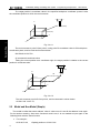
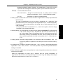
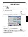
CHAPTER 1 OPERATION PANEL ............................................................................................ 159
1.1
1.2
Panel Layout ................................................................................................................................. 159
Explanation for Panel Functions ................................................................................................ 159
1.2.1
1.2.2
1.2.3
1.2.4
LCD Display Area .............................................................................................................................. 159
Editing Keyboard Area ....................................................................................................................... 160
Screen Operation Keys ..................................................................................................................... 160
Machine Control Area ........................................................................................................................ 161
CHAPTER 2 SYSTEM POWER ON/OFF AND SAFETY OPERATIONS .................................... 165
2.1
2.2
2.3
System Power-on ......................................................................................................................... 165
System Power-off ......................................................................................................................... 165
Safety Operations ........................................................................................................................ 166
2.3.1 Reset Operation ................................................................................................................................ 166
2.3.2 Emergency Stop ................................................................................................................................ 166
2.3.3 Feed Hold .......................................................................................................................................... 167
2.4
2.5
Cycle Start and Feed Hold .......................................................................................................... 167
Overtravel Protection ................................................................................................................... 167
2.5.1 Hardware Overtravel Protection ........................................................................................................ 167
2.5.2 Software Overtravel Protection .......................................................................................................... 168
2.5.3 Overtravel Alarm Release.................................................................................................................. 168
2.6
Stroke Check................................................................................................................................. 168
CHAPTER 3 PAGE DISPLAY AND DATA MODIFICATION AND SETTING .................................. 173
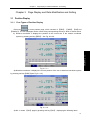
3.1
Position Display ............................................................................................................................ 173
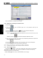
3.1.1 Four Types of Position Display .......................................................................................................... 173
3.1.2 Display of Cut Time, Part Count, Programming Speed, Override and Actual Speed ......................... 175
3.1.3 Relative Coordinate Clearing and Halving ......................................................................................... 176
3.1.4 Bus Monitor Position Page Display ................................................................................................... 177
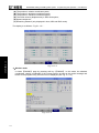
3.2
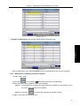
Program Display ........................................................................................................................... 178
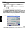
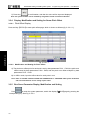
3.3.1 Display, Modification and Setting for Offset ....................................................................................... 181
3.3.1.1 Offset Display .......................................................................................................................................... 181
3.3.1.2 Modification and Setting for Offset Value ............................................................................................. 182
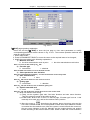
3.3.2 Display, Modification and Setting for Parameters .............................................................................. 183
3.3.2.1 Parameter Display .................................................................................................................................. 183
3.3.2.2 Modification and Setting for Parameter Values ................................................................................... 184
3.3.3 Display, Modification and Setting for Macro Variables ....................................................................... 184
3.3.3.1 Macro Variable Display ........................................................................................................................... 184
3.3.3.2 Modification and Setting for Macro Variables ...................................................................................... 185
3.3.4 Display, Modification and Setting for Screw Pitch Offset ................................................................... 186
3.3.4.1 Pitch Offset Display................................................................................................................................. 186
3.3.4.2 Modification and Setting for Pitch Offset .............................................................................................. 186
3.3.5 Bus Servo Parameter Display, Modification and Setting.................................................................... 186
3.3.5.1 Servo Parameter Display ....................................................................................................................... 188
3.3.5.2 Spindle Parameter .................................................................................................................................. 191
3.3.5.3 Servo Debugging .................................................................................................................................... 193
3.3.5.4 Double-Drive Debugging Tool ............................................................................................................... 198
3.4
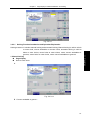
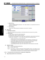
Setting Display .............................................................................................................................. 199
3.4.1 Setting Page ...................................................................................................................................... 199
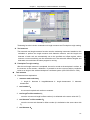
3.4.2 Workpiece Coordinate Setting Page.................................................................................................. 201
3.4.3 Halving and Toolsetting Function ....................................................................................................... 202
XI
GSK990MC Drilling and Milling CNC System Programming and Operation User Manual
3.4.3.1 Halving Function Introduction and Operation Explanation ................................................................ 203
3.4.3.2 Toolsetting Function Introduction and Operation Explanation........................................................... 208
3.4.4 Backup, Restoration and Transmission for Data ................................................................................ 211
3.4.5 Setting and Modification for Password Authority ............................................................................... 214
3.5
3.6
Graphic Display............................................................................................................................. 215
Diagnosis Display ......................................................................................................................... 216
3.6.1 Diagnosis Data Display ..................................................................................................................... 217
3.6.1.1 Signal Parameter Display ....................................................................................................................... 217
3.6.1.2 System Parameter Display .................................................................................................................... 219
3.6.1.3 Bus Parameter Display ........................................................................................................................... 219
3.6.1.4 DSP Parameter Display ........................................................................................................................ 220
3.6.1.5 Wave Parameter Display ........................................................................................................................ 220
3.6.2 Signal State Viewing ......................................................................................................................... 221
3.7
3.8
3.9
Alarm Display ................................................................................................................................ 221
PLC Display ................................................................................................................................... 224
Help Display .................................................................................................................................. 226
CHAPTER 4 MANUAL OPERATION ........................................................................................ 233
4.1
Coordinate Axis Movement ......................................................................................................... 233
4.1.1
4.1.2
4.1.3
4.1.4
4.1.5
4.2
Manual Feed ..................................................................................................................................... 233
Manual Rapid Traverse ..................................................................................................................... 233
Manual Feedrate and Manual Rapid Traverse Speed Selection ....................................................... 233
Manual Intervention........................................................................................................................... 234
Workpiece Alignment ........................................................................................................................ 235
Spindle Control.............................................................................................................................. 237
4.2.1 Spindle Rotation CCW ...................................................................................................................... 237
4.2.2 Spindle Rotation CW ......................................................................................................................... 237
4.2.3 Spindle Stop ...................................................................................................................................... 237
4.2.4 Spindle Automatic Gear Shift ............................................................................................................ 237
4.3
Other Manual Operations ............................................................................................................ 238
4.3.1 Cooling control .................................................................................................................................. 238
4.3.2 Lubricating control ............................................................................................................................. 238
4.3.3 Chip Removal Control ....................................................................................................................... 238
4.3.4 Working Light Control ........................................................................................................................ 238
CHAPTER 5 STEP OPERATION .............................................................................................. 239
5.1
Step Feed ...................................................................................................................................... 239
5.1.1 Selection of Moving Amount .............................................................................................................. 239
5.1.2 Selection of Moving Axis and Direction ............................................................................................. 239
5.1.3 Step Feed Explanation ...................................................................................................................... 240
5.2
5.3
Step Interruption ........................................................................................................................... 240
Auxiliary Control in Step Mode ................................................................................................... 240
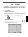
CHAPTER 6 MPG OPERATION .............................................................................................. 241
6.1
MPG Feed ..................................................................................................................................... 241
6.1.1 Moving Amount Selection.................................................................................................................. 241
6.1.2 Selection of Moving Axis and Direction ............................................................................................. 241
6.1.3 MPG Feed Explanation ..................................................................................................................... 242
6.2
Control in MPG Interruption ........................................................................................................ 242
6.2.1 MPG Interruption Operation .............................................................................................................. 242
6.2.2 Relationship between MPG Iinterruption and Other Functions ......................................................... 243
6.3
6.4
Auxiliary Control in MPG Mode .................................................................................................. 243
Electronic MPG Drive Function .................................................................................................. 244
CHAPTER 7 AUTO OPERATION ............................................................................................. 245
7.1
7.2
7.3
7.4
7.5
7.6
7.7
7.8
7.9
XII
Selection of the Auto Run Programs ......................................................................................... 245
Auto Run Start ............................................................................................................................... 245
Auto Run Stop ............................................................................................................................... 246
Auto Running from Any Block ..................................................................................................... 247
Dry Run .......................................................................................................................................... 247
Single Block Execution ................................................................................................................ 247
Machine Lock ................................................................................................................................ 248
MST Lock ....................................................................................................................................... 248
Feedrate and Rapid Speed Override in Auto Run ................................................................... 248
Contents
7.10 Spindle Speed Override in Auto Run ...................................................................................... 249
7.11 Background Edit in Aauto Run ................................................................................................. 249
CHAPTER 8 MDI OPERATION ................................................................................................ 251
8.1
8.2
8.3
8.4
MDI Code Input ............................................................................................................................ 251
MDI Code Execution and Stop ................................................................................................... 252
Word Value Modification and Deletion of MDI Code............................................................... 252
Operation Modes Conversion .................................................................................................... 252
CHAPTER 9 ZERO RETURN OPERATION ............................................................................... 253
9.1
9.2
Concept of Mechanical Zero (Machine Zero) .......................................................................... 253
Steps for Machine Zero Return .................................................................................................. 253
CHAPTER 10 EIDT OPERATION ............................................................................................. 255
10.1
Program Edit ............................................................................................................................... 255
10.1.1 Program Creation ............................................................................................................................ 256
10.1.1.1 Automatic Creation of Sequence Number ......................................................................................... 256
10.1.1.2 Program Content Input ......................................................................................................................... 256
10.1.1.3 Search of Sequence Number, Word and Line Number ................................................................... 258
10.1.1.4 Location Method of the Cursor ............................................................................................................ 258
10.1.1.5 Insertion, Deletion and Modification of a Word ................................................................................. 259
10.1.1.6 Single Block Deletion ........................................................................................................................... 260
10.1.1.7 Deletion of Blocks ................................................................................................................................. 260
10.1.1.8 Deleting Words ...................................................................................................................................... 260
10.1.2 Deletion of a Single Program ........................................................................................................... 261
10.1.3 Deletion of All Programs .................................................................................................................. 261
10.1.4 Copy of a Program .......................................................................................................................... 262
10.1.5 Copy and Paste of Blocks ............................................................................................................... 262
10.1.6 Cut and Paste of Blocks .................................................................................................................. 263
10.1.7 Block Replacement.......................................................................................................................... 263
10.1.8 Rename of a Program ..................................................................................................................... 263
10.1.9 Program Restart .............................................................................................................................. 263
10.2
Program Management .............................................................................................................. 265
10.2.1
10.2.2
10.2.3
10.2.4
10.2.5
Program Directory Search ............................................................................................................... 265
Number of Stored Programs ............................................................................................................ 265
Storage Capacity ............................................................................................................................. 266
Viewing of Program List ................................................................................................................... 266
Program Lock .................................................................................................................................. 266
CHAPTER 11 SYSTEM COMMUNICATION ............................................................................... 267
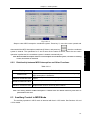
11.1
Serial Communication ............................................................................................................... 267
11.1.1 Program Start................................................................................................................................... 267
11.1.2 Functions ......................................................................................................................................... 267
Serial Port Data Transmission....................................................................................................................... 268
11.1.4 Serial Port On-Line Machining ......................................................................................................... 271
USB Communication ............................................................................................................................. 273
11.2.1 Overview and Pecautions ................................................................................................................ 273
11.2.2 Operations Steps for USB Part Programs ........................................................................................ 273
APPENDIX .............................................................................................. 277
APPENDIX 1 GSK990MC PARAMETER LIST ....................................................................... 279
Parameter Explanation: ........................................................................................................................ 279
1 Bit parameter ........................................................................................................................................... 279
2 Data Parameter ....................................................................................................................................... 296
APPENDIX 2 ALARM LIST ...................................................................................................... 323
XIII
Ⅰ
PROGRAMMING
Ⅰ
Programming
1
GSK990MC Drilling and Milling CNC System
Ⅰ
Programming
2
Programming and Operation User Manual
Chapter 1 Overview
Chapter 1
Overview
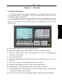
1.1 Product Introduction
8.4 inch color high-resolution LCD display, GSK990MC universal type drill-milling CNC system is
a new upgraded product of GSK990MA, a brand new human-machine interface with friend
characteristics of beauty, and easily use.
The system adopts B type macro programs (statement ) which make programming concise. Its
open PLC supports an on-line edit, compiling to get more convenient and flexible logic control
function, and it is adpted to the CNC milling machine, CNC drilling-milling machine and CNC
grinding machine.
Ⅰ
Programming
z
Max. position speed (max. traverse speed) 60m/min
z
Metric/inch programming, least command increment 0.001mm, 0.0001inch
z
Rotation, zooming, polar cycle, rigid tapping and various of milling-grooving
compound cycle function
z
Time limit stop function
z
Brand new designed human-machine interface with friend characteristics of beauty, and
easily use
z
PLC on-line monitor, edit, compiling and signals trace function
z
Statemnt macro program (macro B) to get concise programming
z
Easily study, use and debugging abundant helps, prompt messages
z
Standard RS232 and USB interfaces to realize file transmission, serial port DNC
machining and USB on-line machining
z 8.4-inch color LCD with Chinese, English, Russian, Spainish and Turkish display
3
GSK990MC Drilling and Milling CNC System
Programming and Operation User Manual
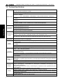
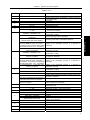
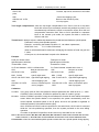
1.2 Technical Specifications
Controlled axes and link axes: 4 axes and 3 link, and optional to 4 axes and 4 link. Each
axis can be set to the linear or rotary
Interpolation: positioning (G00), linear(G01), circular(G02, G03), spirial interpolation
Maximum programmable dimensions: metric∶-99999.999mm~99999.999mm,least command
Motion control
Ⅰ
Programming
Acceleration/d
eceleration
Miscellaneous
function
Tool function
Spindle
function
increment:0.001mm
inch∶-9999.9999inch~9999.9999inch,least command increment:0.0001inch
Electronic gear: command frequency multiplying 1~65536,command frequency division
1~65536
Rapid traverse speed: max. 60m/min,Rapid override:F0, 25%, 50%, 100% to real-time
adjustment
Cutting feedrate: max.15m/min(G94)or 500.00mm/r (G95)
Feedrate override: 0~200% divided into 21 to realize real-time adjustment
MPG feed:0.001, 0.01, 0.1mm;single-step feed:0.001, 0.01, 0.1, 1mm
Front/post acceleration/deceleration : linear or S acceleration/deceleration. Time constant of
acceleration/deceleration can be set
Post acceleration/deceleration: linear or exponential acceleration/deceleration. Time constant of
acceleration/deceleration can be set
Jog, MPG, Single-step mode using post acceleration/deceleration. Rapidly positioning, cutting feed
can select front/post acceleration/deceleration
Specify with M and 2-digit. M function can be customized
System’s interior M commands( they cannot be defined again): end of program M02, M30;program
stop M00;optional stop M01;subprogram call M98;end of subprogram M99
M commands defined by the standard PLC:M03, M04, M05, M08, M09, M10, M11, M16, M17, M18,
M19, M20, M21, M22, M23, M24, M26, M27, M28, M29, M35, M36, M44, M45, M50, M51
●T and 4-digit selection tool●256 groups of tool offset value●length compensation●wear
compensation●C radius tool compensation
●S2 digit(I/O gears control)/ S5 digit(analog output)●max. spindle speed limit●constant surface
speed function
Spindle encoder: encoder lines(100~5000p/r)drive ratio between encoder and spindle:(1~255):
(1~255)
Spindle override:50%~120% divided into 8 to realize real-time adjustment
Tapping cycle, flexible tapping and rigid tapping
Automatic
compensation
Reliability and
safety
●Pitch error compensation:compensation interval, compensation origin can be set. Compensation
range: -999 ~ +999 pulse equivalent
●Backlash compensation : compensate the machine’s backlash value by fixed frequency or
speed-up/down method
●tool length compensation:A or B type length compensation fuction selected by parameter
●tool radius compensation:C type tool compensation function,max. compensation value ±999.999mm
or ±99.9999inch
Status signal:●emergency stop●overtravel●stored travel limit●NC ready signal●servo ready signal
●MST function completion signal ●automatic run start light signal ●automatic running signal ●feed hold
light signal
Self-diagnostic function:●signal●system●bit control●servo●communication●spindle
NC alarm:●program●operation●overtravel●servo●connection●PLC●memory(ROM and RAM)
Operation
function
Display
Program edit
4
●Edit●auto●MDI●zero return●JOG●single step●MPG●DNC
●Single block●skip●dry run●miscellaneous lock●program restart●MPG interrupt●single step
interrupt●MPG interference
●Machine lock●interlock●feed hold●cycl start●emergency stop●external reset signal●external power
supply ON/OFF
●GSK 990MC using resolution 800×600’s color 8.4-inch display
●Chinese, English, Russian, Spainish and Turkish display selected by parameter
●Position message ●user program ●system setting ●PLC ● diagnotic message ●system parameter
●graph ●alarm message ●help
●Actual feedrate, spindle speed ●real-time wave diagnosis ●system run time and other NC commands
and status message
Program capacity:57M, store up to 400 programs
Chapter 1 Overview
●Program preview ●program edit ●background edit
PLC
function
PLC processing speed:3us/step;up to 4700 steps;10 basic command,35 functional commands;
ladder diagram on-line edit;
I/O input/output:48/48,extensible
Communication RS-232 serial port, USB communication interface to realize file transfer, serial port DNC machining
function
function and USB on-line machining function
Adaptive drive
GSK GE series bus AC servo drive unit, DA98 series, GS series digital AC servo drive unit and SJT
servo motor
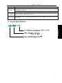
1.3 Product Model Definition
Ⅰ
Programming
5
GSK990MC Drilling and Milling CNC System
Ⅰ
Programming
6
Programming and Operation User Manual
Chapter 2 Programming Fundamentals
Chapter 2
Programming Fundamentals
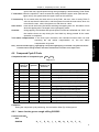
2.1 Controllable Axis
Table
2-1-1
Item
GSK990MC
Basic controllable axes
3(X, Y, Z)
Total extended controllable axes
Up to 4
Name of 3 basic axes is defaulted to X, Y, Z.
P005 sets the controllable axis quantity and P175-P178 sets each additional axis’ name, such as
A, B, C’s axis name.
Note: when the input axis name is repetitive, the system automatically initializes it to X, Y, Z, A.
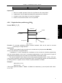
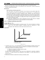
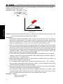
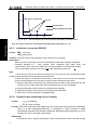
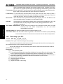
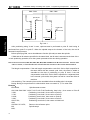
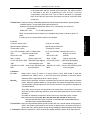
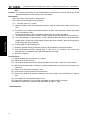
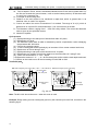
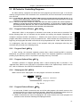
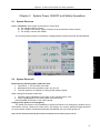
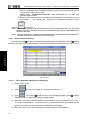
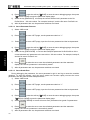
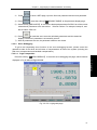
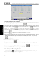
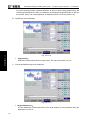
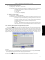
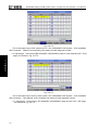
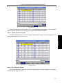
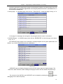
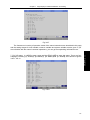
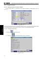
2.3 Axis Display
When the additional axis is set to the rotary, the rotary axis’ unit is displayed to deg. When it is set
to the linear, the system display it is the same that of X/Y/Z, and its unit is mm. The following is an
example when the 4th is rotary axis.
Fig. 2-3-1
7
Programming
2.2 Axis Name
Ⅰ
On account of some machines’ structure design requirement, an additional axis is required to
use for the maneuver workbench and rotary workbench. The axis can be linear or rotary. For
GSK990MC, its each axis is set to the linear or rotary by bit parameter No.8#4~No.8#7.
GSK990MC Drilling and Milling CNC System
Programming and Operation User Manual
2.4 Coordinate System
2.4.1
Machine Coordinate System
Ⅰ
Programming
A special point used to the machining reference on the machine is called a machine zero. The
machine tool manufacturers have set a machine zero on each machine. Taking the machine zero as
an origin sets a coordinate system is called a machine coordinate system. After power-on, executing
manual returning to the machine zero can create a machine coordinate system. Once the machine
coordinate system is set, it remains unchanged till the power supply is turned off or the system is
restarted or the Emergency Stop key is pressed.
The system uses the right-hand Cartesian coordinate system, its vertical movement motion in
spindle direction is Z-axis motion. From the spindle to the workpiece direction, the motion of the
spindle box approaching the workpiece is Z’s negative motion, and the motion of be far away from the
workpiece is Z’s positive motion; other directions is decided by right-hand Cartesian coordinate
system.
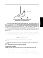
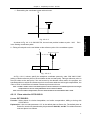
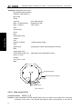
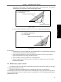
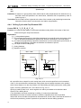
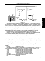
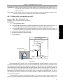
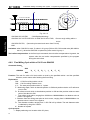
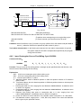
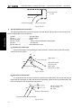
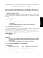
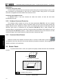
2.4.2
Reference Point
On the CNC machine, there is a special position where a tool change is performed or a
coordinate system is set is called a reference point. Using the reference point return function can
easily traverse the tool to the position. Generally, the reference point and machine zero of the CNC
drilling-milling system coincide.
Reference point
Tool
Workpiece
Workbench
Fig. 2-4-2-1
There are two methods to make the tool traverse to the reference point:
1.
Manual reference point return(Refer to Section 9 Zero Operation, Operation)
2.
Automatic reference point return
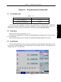
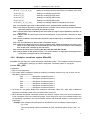
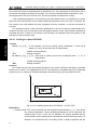
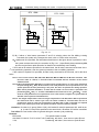
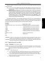
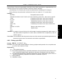
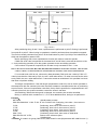
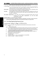
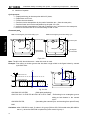
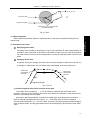
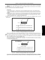
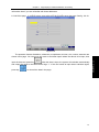
2.4.3
Workpiece Coordinate System
When the system machines a workpiece, the used coordinate system is called a workpiece
coordinate system(called a part coordinate system). A workpiece coordinate system is set in advance
by the CNC (set a workpiece coordinate system).
8
Chapter 2 Programming Fundamentals
Tool
Z
Y
Z
Y
Z
Program
X
Y
X
Instruction
X
Coordinate system
CNC system
Machining drawing
Machine tool
Fig. 2-4-3-1
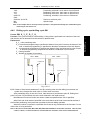
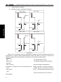
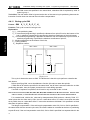
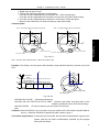
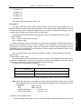
I) Using the part reference point
II) Fixing the part directly on the fixture
Workpiece reference point
Workpiece
fixture
Reference point
Fixed distance
Align the tool center to the workpiece reference
point, a n d s pecify the workpiece coordinate
system by CNC instructions at this position. Then
the workpiece coordinate system c oincides with
the programming Coordinate system.
Because the tool center can not be located at the
workpiece reference point, the tool is located at a
position (can be reference point) the distance of
w h i c h to the base point i s k n o w n . S et the
workpiece coordinate system u s i n g this k n o w n
distance (e.g. G92).
Fig. 2-4-3-2
One machining program sets a workpiece coordinate system(select one workpiece coordinate
system). Setting a workpiece coordinate system can move its origin to change.
Using the following two methods can set a workpiece coordinate system:
1. For using G82, See Section Programming 4.2.1.
2. For using G54~G59, See Section Programming4.2.8.
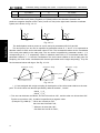
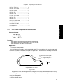
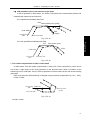
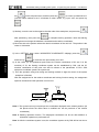
2.4.4
Absolute Coordinate Programming and Relative Coordinate Programming
Definishing an axis’ movement method is divided into two methods:an absolute value definition
and relative value definition. The absolute value definition is to use an end point’s coordinate value of
the axis movement to perform a programming is called an absolute coordinate programming. The
relative coordinate definition is to use an axis movement value to directly program, which is called an
relative coordinate programming(also called an incremental coordinate programming).
1) an absolute coordinate value
9
第一篇
编程说明篇
Ⅰ Programming
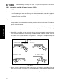
The tool in the CNC commanding the workpiece coordinate system cuts a workpiece to the
shape described in the drawing according to the programmed coordinate system’s command
programs represented in the machining drawing, which must confirm their relative relationship
between the machine coordinate system and the workpiece coordinate system. The method of
confirming their relationship is called alignment. There are different methods according to the
workpiece’s shape and machining quantity.
GSK990MC Drilling and Milling CNC System
Programming and Operation User Manual
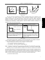
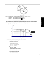
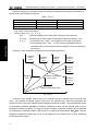
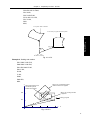
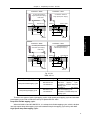
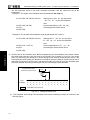
The target position’s coordinate value in the specified workpiece coordinate system is also
the coordinate position to which the tool traverses.
Z
A(15,60,40)
B (10,30,20)
Y
X
Ⅰ
Fig. 2-4-4-1
Programming
The tool traverses to point B from point A, using point B’s coordinate value in G54 workpiece
coordinate system, and its command is shown below:
G90 G54X10 Y30 Z20 ;
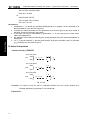
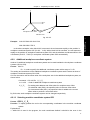
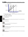
2) Incremental coordinate value
Taking the current position as a coordinate origin, the target position is relative to the current
position’s coordinate value.
Tool
Z
30
A
10
40
B
Y
X
Fig. 2-4-4-2
The tool traverses to point B from point A, and its command is shown below:
G0 G91 X40 Y-30 Z-10;
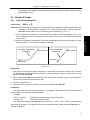
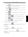
2.5 Modal and Non-Modal (Simple)
The modal is called that some address’ value is value once it is set till the address is set again.
For its another meaning, after some functional word is set, it is not needed to input again in the
following block with the same function.
¾
For example:
G0 X100 Y100; (Rpaidly position to X100 Y100)
10
Chapter 2 Programming Fundamentals
X20 Y30;
(Rpaidly position to X20 Y30,G0 is modal and it can be omitted)
G1 X50 Y50 F300;
(Execute linear interpolation to X50 Y50,feedrate 300mm/min G0→G1)
X100;
(Execute linear interpolation to X100 Y50,feedrate 300mm/min,G1, Y50,
F300 are modal and can be omitted)
G0 X0 Y0;
(Rpaidly position to X0 Y0)
The initial state is the defaulted mode after the system is turned off. See Table 4-1-2.
¾
For example:
O00001
X100 Y100;(Rpaidly position to X100 Y100,G0 is the system’s initial state)
G1 X0 Y0 F100;(Execute linear interpolation to X0 Y0,feedrate per minute:100mm/min)
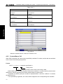
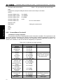
Table 2-5-1
Modal G function
Modal
Modal M function
Non-modal
Non-modal G function
Non-modal M function
functional command’s modal and non-modal
G functions in the group can mutually cancel. Once each function is
executed , it is valid till it is cancelled by other G function in the the
group
M functions in the group are mutually replaced. Each functions is valid
before it are replaced by other function in the group
It is valid only in the specified block, and it is replaced when the block
ends.
It is valid only in the block in which it is
11
第一篇
编程说明篇
Ⅰ Programming
The non-modal is defined that a corresponding address’ value is valid in a block in which the
command is, and it must be specified again in the next block. G commands in group 00 are shown in
Table 4-1-2.
Its modal and non-modal description of functional word is referred to Table 2-5-1.
GSK990MC Drilling and Milling CNC System
Ⅰ
Programming
12
Programming and Operation User Manual
Chapter 3 Structure of an Part Program
Chapter 3
Structure of an Part Program
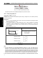
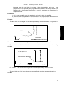
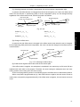
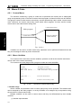
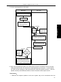
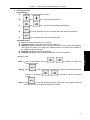
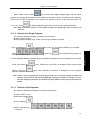
3.1 Structure of a Program
A program consists of many blocks, and a block is composed of words. Each block is separated
by a code for end of block (ISO uses LF, EIA uses CR). Using a character “;” means a code for end
of block.
Program
name
Word
Ⅰ
Programming
Sequence
number
Block end code
Block
Program end
Fig. 3-1-1
structure of a program
A group of commands for controlling the CNC machine to finish workpiece machining is called a
program. After the compiled program is input to the CNC system, the system make the tool move
along a straight line or an arc, or rotate or stop the spindle. Please edit these commands according to
the actual movement sequence of the machine tool in the program. Structure of the program is shown
in Fig. 3-1-1.
3.1.1
Program Name
In the system, the system’s memory can store many programs. In order to mutually differentiate
these programs, each program begins with an address O followed by a five-digit number, which is
shown in Fig. 3-1-1-1.
13
GSK990MC Drilling and Milling CNC System
3.1.2
Programming and Operation User Manual
Sequence number and program block
Ⅰ
Programming
A program consists of many commands, and an command unit is called a block (see Fig. 3-1-1).
These blocks are separated by a code for end of program (see Fig. 3-1-1). In the manual, the code of
end of block is represented by a character“;”.
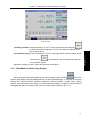
Address N with a five-digit sequence number behind it can be used at the beginning of the block
(see Fig. 3-1-1), and the leading zero can be omitted. Sequence numbers (whether the sequence
number is inserted is set by Parameter NO: 0 # 5, or set the number in the setting page directly. See
Section 3.4.1 in Operation) can be specified in a random order, and the intervals between them can
be unequal (set by Data Parameter P210). They can be specified in all blocks, or just in some
important blocks. However, the numbers should be arranged in ascending order according to general
machining sequence. It is for convenience to insert sequence numbers to important parts of the
program (e.g. inserting sequence number for tool changing or when the index table moves to a new
machining plane).
Note: The N command is not taken as a line number when it and G10 are in the same block.
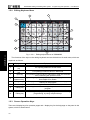
3.1.3
Word
A word (See 3-1-3-1) is an element that composes a block. It consists of an address and its following
digits (with sign +or - before the digits sometimes).
X
100
A ddress Figure
W ord
Fig. 3-1-3-1 General structure of a word
An address is one of the English letters (A~Z). It specifies the meaning of its following digits. In
the system, the used addresses and their meanings as well as their ranges are shown in Fig. 3-1-3-1.
Sometimes, an address may have different meanings based on different preparatory functions.
An address is used more than one time in the same command, and whether an alarm is issued is
set by bit parameter N0:32#6.
14
Chapter 3 Structure of an Part Program
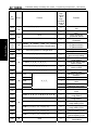
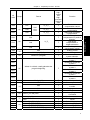
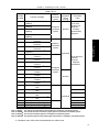
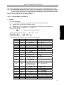
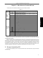
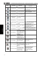
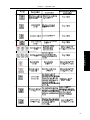
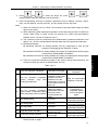
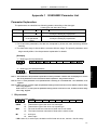
Table 3-1-3-1
Address
Range
Meaning
A, B, C
Set by data parameter P175~P178
D
0~255
Address of axis name
Radius offset number. D0 defaults to 0 and it cannot be
changed by users
Not used
Feedrate per minute
Feedrate per turn
Preparation function
Operator in G65
Length offset number. H0 is defaulted to 0, which can
not be set or modified.
X vector between arc center and start point(arc/spiral
interpolation, scaling)
E
F
G
H
0.001~99999.999(mm/min)
0.001~500(mm/r)
00~99
01~99
0~255
-99999999~99999999(mm)
J
K
0≤J≤99999.999mm,its absolute value
used if it is negative
J value should be moare than{(value data
parameter P269 set value * tool radius)+
tool radius}*2. The screwing cutting radius
should be less than{(J/2)-tool radius}
0<J≤99999.999mm,its absolute value
used if it is negative
-99999999~99999999(mm)
1~99999
1~99999
Less than tool diameter and more than 0
L
Less than tool diameter and more than 0,
its absolute value used if it is negative
0 mm ~99999999mm,its absolute value
used if it is negative
M
N
O
P
Set by data parameter P204
0~99999
0~999
0~99999
0~99999.9999(ms)
1~99999
-9999.9999~9999.9999
Data parameter P281~282
Q
R
S
T
-99999.999~99999.999(mm)
-99999999~99999999(mm)
-99999.999~99999.999(mm)
Set by data parameter P205
00~04
Set by data parameter P206
Finishing circle radius in G24/G25, G26/G32
Width of the rectangular grooves in X direction in
G33/G34
Width of the rectangular grooves in X direction in
G35/G36, G37/G38
Y vector between arc center and start point(arc/spiral
interpolation, scaling)
Distance between finishing start point and circle center
in G24/G25, G26/G32
Width of the rectangular grooves in Y direction in
G33/G34
Width of the rectangular grooves in Y direction in
G35/G36, G37/G38
Z vector between arc center and start point(arc/spiral
interpolation, scaling)
Fixed cycle times
Times of recalling a subprogram
Cutting width increment of interior grooving cycle in XY
in-plane in G22/G23
Cutting width increment in specified plane in G33/G34
Distance between fineing start point and rectangular
side in X direction in G37/G38
Miscellaneous function output, program executed flow,
subprogram call
Block number
Parameter number(G10 revised online)
Program name
Pause time
Calling subprogram number
Scaling
Pause time at the hole bottom in the fixed cycle or at
point R when retracting
Cutting depth or hole bottom’s offset in fixed offset
Arc radius/angle displacement/corner value
R-plane in fixed cycle
Specify spindle speed
Multi-gear spindle output
Tool function
15
Programming
-99999999~99999999(mm)
Interior grooving radius in G22/G23
Ⅰ
I
I value should be more than the radius of
current tool
(tool radius+J)<I≤99999.999mm,its
absolute value used if it is negative
I value should be more than{(data
parameter P269 set value* tool radius)+
tool radius}*2.The screwing cutting radius
should be less than{(I/2)-tool radius}
0<I≤99999.999mm,its absolute value
used if it is negative
GSK990MC Drilling and Milling CNC System
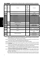
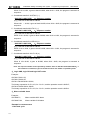
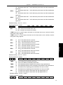
Address
U
V
W
X
Range
Ⅰ
Programming
Z
Meaning
Set by data parameter P175~178
Range of U: D/2≤|U|≤the smaller one
between I/2 and J/2
Set by data parameter P175~178
More than 0
Set by data parameter P175~178
-99999.999~99999.999(mm)
Address of axis name
Corning arc radius in fixed cycle
Address of axis name
Distance to unprocessed plane when rapidly cutting
Address of axis name
Should be more than 0(if the fist cut depth
is more than the groove bottom, the user
directly machines the workpiece at the
bottom)
Set by data parameter P175~178
0~9999.999(S)
Y
Programming and Operation User Manual
fist cut depth down in Z direction from R-plane in fixed
cycle
Address of axis name
Coordinate address in X direction
Specify pause time
Set by data parameter P175~178
Address of axis name
-99999.999~99999.999(mm)
Coordinate address in Y direction
Set by data parameter P175~178
Address of axis name
-99999.999~99999.999(mm)
Coordinate address in Z direction
All described in Table 3-1-3-1 are limited values for the CNC device, but the limit for the
machine tool is not described here. Therefore, users are required to refer to the manual provided
by the machine tool builder besides this one, in order to get a good understanding of the
programming limits before programming.
Note: each word should not exceed 79 characters.
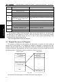
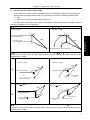
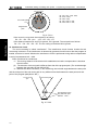
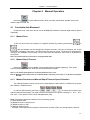
3.2 General Structure of a Program
The program is divided into main program and subprogram. In general, the CNC system is
actuated by the main program. If an Command for calling the subprogram is executed in the main
program, the CNC system acts by the subprogram. When an Command for returning to the main
program is executed in the subprogram, the CNC system will return to the main program and execute
the following blocks. The program execution sequence is shown in Fig.3-2-1.
M ain program
S ubprogram
C om m and 1
C om m and 1
C om m and 2
C om m and 2
……
……
C alling subprogram
……
C om m and N
……
……
M 30
M 99 R eturning to
m ain program
Fig. 3-2-1
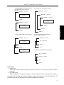
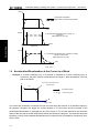
The structure of a subprogram is consistent with that of a main program.
16
Chapter 3 Structure of an Part Program
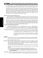
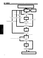
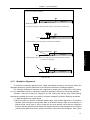
If a program contains a fixed sequence or frequently repeated pattern, the sequence or pattern
can be stored as a subprogram in the memory to simplify the program. The subprogram can be called
in Auto mode, usually by M98 in the main program. Besides, the subprogram called can also call
another subprogram. The subprogram called from the main program is called the one-level
subprogram. Up to 4 levels subprogram can be called in a program (Fig.3-2-2). The last block of a
subprogram is the Command M99 used for returning to the main program. After the return, the blocks
following the subprogram calling block are executed. (If the last block of a subprogram is ended with
M02 or M03, the system will also return to the main program and proceed to the next block, just as
ended with M99.)
When a main program is ended with M99, its execution will be repeated.
Main program
Subprogram
O10000;
…
…
…
M98 P20000;
…
…
…
…
M99;
O20000;
…
…
…
M98 P30000;
…
…
…
…
M99;
O30000;
…
…
…
M98 P40000;
…
…
…
…
M99;
One-level nesting
Fig. 3-2-2
Subprogram
O40000;
…
…
…
Programming
Subprogram
Ⅰ
O00001;
…
…
…
M98 P10000;
…
…
…
…
M30;
Subprogram
…
…
…
…
M99;
Two-level nesting Three-level nesting Four-level nesting
Quadruple subprogram nesting
The Command can be called with a subprogram. The same subprogram can be called up to
9999 times consecutively or repeatedly.
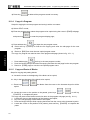
3.2.1
Subprogram Writing
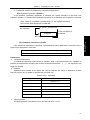
Write a subprogram following the format below
; Subprogram number
O
……
……
Subprogram
……
M99;
Subprogram end
Fig. 3-2-1-1
Write the subprogram number behind the address O at the beginning of the subprogram, and
end the subprogram with Command M99 (M99 format as above).
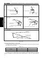
3.2.2
Subprogram Call
The subprogram is called by the call Command of the main program or subprogram. The format
of the subprogram is as follows:
17
GSK990MC Drilling and Milling CNC System
M98 P
Programming and Operation User Manual
L
Repetitive called times
Called subprogram number
Fig. 3-2-2-1
● If no repetition count is specified, the subprogram is called just once.
(Example) M98 P1002L5 ;(It means a subprogram with number 1002 is repeatedly called 5
times)
● Execution sequence of calling a subprogram from a main program
1 2 3
Main program
Subprogram
N0010 …… ;
O10100 ;
Ⅰ
N0020 …… ;
N1020…… ;
Programming
N0030 M98 P10100L3 ;
N1030…… ;
N0040 …… ;
N1040…… ;
N0050 M98 P10100 ;
N1050…… ;
N0060…… ;
N1060 …… M99;
Fig. 3-2-2-2
A subprogram can call another subprogram in the same way as a main program calls a
subprogram.
Note 1: An alarm is given when no subprogram number specified with address P is detected.
Note 2: Subprograms with number 90000~99999 are the system reserved programs. When users call such
kind of subprograms, the system can execute them but not display them.
Note 3: A subprogram can nest a quadruple.
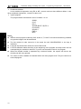
3.2.3
Program End
The program begins with a program name, and ends with M02, M30 or M99 (see Fig. 3-2-2-2).
For the end code M02, M30 or M99 detected in program execution: If M02 or M03 is executed in a
program, the program is terminated, and the reset state is entered; M30 can be set by bit parameter
N0.33#4 to return to the program beginning, and M02 can be set by bit parameter N0.33#2 to return
to the program beginning. If M99 is executed in a program, the control returns to the beginning of the
program, and then executes the program repeatedly; if M99, M02 or M30 is at the end of the
subprogram, the control returns to the program that calls the subprogram and goes on executing the
following blocks.
18
Chapter 4 Preparatory Function : G Code
Chapter 4
Preparatory Function : G Code
4.1 Types of G Code
Preparatory function, represented by a G code with a number behind it, defines the meaning of
the block where it is located. G codes are divided into the following two types:
Table 4-1-1
Type
Meaning
Non-modal G
Valid only in the commanded block
code
Still remain valid effective before other G codes in the same group
Ⅰ
Modal G code
Programming
Example: G01 and G00 are modal in the same group.
G01 X _ ;
Z ___ ; G01 valid
X ___ ; G01 valid
G00 Z__; G00 valid
It is the normal machining mode when the system bit parameter NO:0#7 is set to 0, and the
high-speed and high-precision machining mode when NO:0#7 set to 1.
Note 1: F: indicates the normal machining mode; T: indicates high-speed and high-precision
machining mode
Note 2: Refer to System Parameter List for details.
Table 4-1-2
G
code
Format
Whether
highspeed
and
highprecision
mode is
valid
G00 X_Y_Z_
T
G01 X_Y_Z_F_
T
Group
*G00
G01
01
G02
G02
G03
X_Y_
G codes and their functions
R_
I_J_
F_;
G03
T
G04 P_
G04
G10
*G11
T
00
G10 L_N_P_R_
G11
or
G04 X_
Function
Positioning (rapid
traverse)
Linear interpolation
(cutting feed)
Circular interpolation CW
(clockwise)
Circular interpolation
CCW (counter clockwise)
F
Dwell, exact stop
F
Programmable data input
Programmable data input
cancel
F
19
GSK990MC Drilling and Milling CNC System
G
code
Group
Format
G12 X_Y_Z_ I_J_K_
*G12
16
G13
Programming and Operation User Manual
Whether
highspeed
and
highprecision
mode is
valid
F
G13
F
G15
*G15
11
G16
G16
F
F
Ⅰ
Programming
*G17
G18
G19
02
Written in blocks, used for circular
interpolation and tool radius compensation
F
G20
*G21
06
Must be specified in a single block
F
G22
G23
G24
09
G25
G22 X_Y_Z_R_I_L_W_Q_V_D_F_ K
F
G23 X_Y_Z_R_I_L_W_Q_V_D_F_K
F
G24 X_Y_Z_R_I_J_D_F_K_
G25 X_Y_Z_R_I_J_D_F_K_
G26 X_Y_Z_R_I_J_D_F_K_
G26
F
F
F
G27
G27
T
G28
G28
T
G29
00
X_Y_Z_
G30Pn
G30
G31
G33
G33X_Y_Z_R_I_J_L_W_Q_V_U_D_F_K
G34X Y_Z_R_I_J_L_W_Q_V_U_D_F_K
G34
09
T
T
G31
G32 X_Y_Z_R_I_J_D_F_K_
G32
G35
G29
G35 X_Y_Z_R_I_J_L_ U_D_F_K_
F
F
F
F
F
G36
G36 X_Y_Z_R_I_J_L_ U_D_F_K_
F
G37
G37 X_Y_Z_R_I_J_L_ U_D_F_K_
F
G38
G38 X_Y_Z_R_I_J_L_ U_D_F_K_
F
G39
20
00
G39
F
Function
Stored stroke detection
ON
Stored stroke detection
OFF
Polar coordinate
Command cancel
Polar coordinate
Command
XY plane selection
ZX plane selection
YZ plane selection
Input in inch
Input in metric
CCW inner circular
groove rough milling
CW inner circular groove
rough milling
CCW fine milling cycle
within a circle
CW fine milling cycle
within a circle
CCW outer circle
finishing cycle
Reference point return
detection
Reference point return
Return from reference
point
2nd, 3rd and 4th
reference point return
Skip function
CW outer circle finishing
cycle
CCW rectangular groove
rough milling
CW rectangular groove
rough milling
CCW rectangular groove
rough milling cycle
CW rectangular groove
rough milling cycle
CCW rectangular outside
groove finishing cycle
CW rectangular outside
groove finishing cycle
Corner offset circular
interpolation
Chapter 4 Preparatory Function : G Code
G
code
Group
*G40
G41
Format
G17
07
G42
G19
D_X_Z_
T
D_Y_Z_
T
08
T
H_Z_
G44
G49
T
T
G50
T
G51 X_ Y_ Z_ P_
T
00
Written in a program
T
05
Written in a block, usually placed at the
program beginning
T
G60 X_ Y_ Z_
G61
T
T
G62
T
G63
G64
T
T
12
*G54
G55
G56
G57
G58
G59
G60
G61
G62
00/01
14
G63
*G64
G65
00
G68
*G69
G73
G74
G76
*G80
13
09
G65 H_P# i Q# j R# k
T
G68 X_ Y_ R_
T
G69
T
G73 X_Y_Z_R_Q_F_;
G74 X_Y_Z_R_P_F_;
G76 X_Y_Z_Q_R_P_F_K_;
Written in a block with other programs
F
F
F
F
Tool radius
compensation cancel
Left-hand tool radius
compensation
Right-hand tool radius
compensation
Tool length
compensation in positive
direction
Tool length
compensation in
negative direction
Tool length
compensation cancel
Scaling cancel
Scaling
Machine coordinate
system selection
Workpiece coordinate
system 1
Workpiece coordinate
system 2
Workpiece coordinate
system 3
Workpiece coordinate
system 4
Workpiece coordinate
system 5
Workpiece coordinate
system 6
Unidirectional positioning
Exact stop mode
Automatic corner
override
Tapping mode
Cutting mode
Macro program
Command
Coordinate rotation
Coordinate rotation
cancel
Peck drilling cycle
Left-hand tapping cycle
Fine boring cycle
Canned cycle cancel
21
Programming
G53
T
Function
Ⅰ
G51
D_X_Y_
G43
*G49
*G50
G40
G41
G42
G18
G43
G44
Whether
highspeed
and
highprecision
mode is
valid
GSK990MC Drilling and Milling CNC System
G
code
Group
G81
G82
Ⅰ
Programming
G83
G84
G85
G86
G87
G88
G89
*G90
G91
G92
*G94
G95
Format
G81
X_Y_Z_R_F_;
G82
X_Y_Z_R_P_F_;
G83 X_Y_Z_R_Q_F_;
G84 X_Y_Z_R_P_F_;
G85 X_Y_Z_R_F_;
G86 X_Y_Z_R_F_;
G87 X_Y_Z_R_Q_P_F_;
G88 X_Y_Z_R_P_F_;
G89 X_Y_Z_R_P_F_;
Programming and Operation User Manual
Whether
highspeed
and
highprecision
mode is
valid
F
F
F
F
F
F
F
F
F
Drilling cycle (spot drilling
cycle)
Drilling cycle (counter
boring cycle)
Peck drilling cycle
Right-hand tapping cycle
Boring cycle
Boring cycle
Back boring cycle
Boring cycle
Boring cycle
Absolute programming
Incremental programming
Floating coordinate
system setting
03
Written into blocks
T
00
G92 X_Y_Z_
T
G94
T
Feed per minute
G95
T
G96S_
T
G97S_
T
Written into blocks
T
Feed per revolution
Constant surface speed
control (cutting speed)
Constant surface speed
control cancel(cutting
speed)
Return to initial plane in
canned cycle
Return to point R plane in
canned cycle
04
G96
15
*G97
*G98
10
G99
Function
Note 1: If modal Commands and non-modal Commands are in the same block, the non-modal commands
take precedence. At the same time, the corresponding modes are changed according to the other
modal Commands in the same block, but not executed.
Note 2: For the G code with sign *, when the power is switched on, the system is in the state of this G
code (some G codes are determined by bit parameter NO:31#0~7).
Note 3: The G codes of group 00 are all non-modal G codes except G10, G11, G92.
Note 4: An alarm occurs if G codes not listed in this table are used or G codes that cannot be selected
are specified.
Note 5: G codes from different groups can be specified in a block, but 2 or more G codes from the same
group can not be specified in a block by principle. If no alarm occurs when two or more G codes
in the same group are in a block after parameter setting, the latter G code functions.
Note 6: If a G code of group 01 is in the same block with a G code of group 09, the G code of group 01
prevails. In canned cycle mode, if G codes from 01 group are specified, the canned cycle will be
cancelled automatically and the system turns into G80 state.
Note 7: G codes are represented by group numbers respectively based on their types. Whether the G
codes of each group are cleared after reset or emergency stop is determined by bit parameter
NO:35#0~7 and NO:36#0~7.
Note 8: If the rotation scaling Command and the Command of group 01 or that of group 09 share the
same block, the rotation scaling Command will be taken, and the modes of group 01 or group 09
22
Chapter 4 Preparatory Function : G Code
are changed. If the rotation scaling Command and the Command of group 00 share the same
block, an alarm occurs.
4.2 Simple G Codes
4.2.1
Rapid Positioning G00
Code format: G00 X_Y_Z_
Linear interpolation
positioning
Start position
Start position
End position
End position
Fig. 4-2-1-1
Explanation:
1. After G00 is executed, the system changes the current tool move mode for G00 mode. Whether
the default mode is G00 (parameter value is 0) or G01 (parameter value is 1) after power-on is set
by bit parameter No.031#0.
2. With no positioning parameter specified, the tool does not move and the system only changes the
mode of the current tool movement for G00.
3. G00 is the same as G0.
4. The G0 speed of axes X, Y, Z and 4th is set by data parameters P88~P91.
Limitations:
The rapid traverse speed is set by parameter. The speed F specified in the G0 Command is the
cutting speed of the following machining blocks.
Example:
G0 X0 Y10 F800;
Feeding at the speed set by system parameter
G1 X20 Y50;
Using the feedrate of F800
The rapid positioning speed is adjusted by the keys F0%, 25%, 50%, 100% on the operation
panel (see fig. 4-2-1-2 ). The speed to which F0 corresponds is set by data parameter P93 and it is
common to all axes.
23
Programming
Non-linear interpolation
positioning
Ⅰ
Function: G00 command. The tool moves to the position in the workpiece system specified with the
absolute or an incremental command at a rapid traverse speed. The bit parameter
NO:12#1. sets to select one of the following two tool paths (Fig. 4-2-1-1).
1. Linear interpolation positioning: The tool path is the same as linear interpolation (G01). The
tool is positioned within the shortest time at a speed not more than the rapid traverse speed
of each axis. 1.
2. Nonlinear interpolation positioning: The tool is positioned at the rapid traverse speed of each
axis respectively. The tool path is usually not straight.
GSK990MC Drilling and Milling CNC System
Programming and Operation User Manual
Fig. 4-2-1-2 Keys for rapid feedrate override
Note: Note the position of the worktable and workpiece to prevent tool collision.
4.2.2
Linear Interpolation 01
Code format:
G01 X_ Y_ Z_ F_
Function: The tool moves to the specified position along a straight line at the feedrate (mm/min)
specified by parameter.
Ⅰ
Explanation:
Programming
1. X_ Y_ Z_ are the coordinates of the end point. Since they are related to the coordinate system,
please see sections 3.3.1~3.3.3.
2. The feedrate specified by F keeps effective till a new F value is specified. The feedrate
specified by F code is calculated by an interpolation along a straight line. If F code is not
specified in a program, the default F value at system Power On is used (see data parameter
P87 for details).
Program example (Fig. 4-2-2-1)
G01 X200 Y100 F200 ;
Y
E nd point
10 0
S tart point
2 00
Note: feedrate of each axis is as follows:
G01 Xα Yβ ZγFf;
In this program:
X
Feedrate of X axis
Feedrate of Y axis:
Feedrate of Z axis:
L=
Fig. 4-2-2-1
Note:
1. All code parameters are positioning parameters except for F code. The upper limit of
feedrate F is set by data parameter P96. If the actual cutting feedrate (after using feedrate
override) exceeds the upper limit, it is clamped to the upper limit (unit: mm/min). The lower
limit of the feedrate F is set by data parameter P97. If the actual cutting feedrate (after using
feedrate override) exceeds the lower limit, it is clamped to the lower limit (unit: mm/min).
2. The tool does not move when no positioning parameter is specified behind G01, and the
24
Chapter 4 Preparatory Function : G Code
system only changes the mode of the current tool movement mode for G01. By altering the
system bit parameter NO:31#0, the system default mode at power-on can be set to G00
(value is 0) or G01 (value is 1).
4.2.3
Circular (Helical) Interpolation G02/G03
A. Circular interpolation G02/G03
Prescriptions for G02 and G03:
The plane circular interpolation means that the arc path is finished according to the specified
rotation direction and radius (or circle center) from the start point to end point in the specified plane.
Since the arc path can not be determined only by the start point and the end point, other conditions
are required:
Arc rotation direction(G02,G03)
¾
Circular interpolation plane(G17, G18, G19)
Ⅰ
¾
G17
G02
X_Y_
G03
R_
F_;
I_J_
Arc in ZX plane
G18
G02
G03
X_Z_
R_
I_K_
F_;
Arc in YZ plane
G19
G02
G03
Y_Z_
R_
J_K_
F_;
Table 4-2-3-1
Item
Content
1
Plane specification
2
Rotation direction
3
G90 mode
End point position
G91 mode
4
Distance from start point
to circle center
Command
G17
G18
G19
G02
G03
Two axes of X,Y
and Z axes
Two axes of X,Y
and Z axes
Two axes of I,J and
K
axes
Meaning
Arc specification on XY plane
Arc specification on ZX plane
Arc specification on YZ plane
CW rotation
CCW rotation
End point coordinate in workpiece
coordinate system
Coordinate of end point relative to
start point
Coordinate of circle center relative
to start point
25
Programming
¾ Circle center coordinate or radius, which thus leads to two Command formats: Circle
center coordinate I, J ,K or radius R programming.
Only the three points above are all determined, could the interpolation operation be done in
coordinate system.
The circular interpolation can be done by the following Commands to make the tool move along an
arc, as is shown below:
Arc in XY plane
GSK990MC Drilling and Milling CNC System
5
Programming and Operation User Manual
Arc radius
R
Arc radius
Feedrate
F
Arc tangential speed
CW and CCW on XY plane (ZX plane or YZ plane) refer to the directions viewed in the
positive-to-negative direction of the Z axis (Y axis or X axis) in the right-hand Cartesian coordinate
system, as is shown in Fig. 4-2-3-1.
X
Y
Z
G03
G03
G03
G02
G02
G02
Z
X
Y
G18
G17
G19
Ⅰ
Fig. 4-2-3-1
Programming
The default plane mode at power-on can be set by bit parameters NO:31#1 and #2.
The end point of an arc can be specified by parameter words X, Y and Z. It is expressed as
absolute values in G90, and incremental values in G91. The incremental values are the coordinates
of the end point relative to the start point. The arc center is specified by parameter words I, J, K,
corresponding to X, Y, Z respectively. Either in absolute mode G90, or in incremental mode G91,
parameter values of I, J, K are the coordinates of the circle center relative to the arc start point (for
simplicity, the circle center coordinates with the start point taken as the origin temporarily). They are
the incremental values with signs. See Fig. 4-2-3-2.
Start point
I
Start point
Start point
J
Center
End point(Y,Z)
End point(Z,X)
End point(X,Y)
K
I
Center
K
Center
J
Fig. 4-2-3-2
I, J, K are assigned with a sign according to the direction of the circle center relative to the start
point. The circle center can also be specified by radius R besides I, J and K.
G02 X_ Y_ R_ ;
G03 X_ Y_ R_ ;
1. Two arcs can be drawn as follows; one arc is more than 180°, and the other one is less than 180°.
For the arc more than 180°, its radius is specified by a negative value.
(Example: Fig. 4-2-3-3) ① When arc is less than 180°,
G91 G02 X60 Y20 R50 F300 ;
② When arc is more than 180°,
G91 G02 X60 Y20 R-50 F300 ;
26
Chapter 4 Preparatory Function : G Code
R=50
End point
1
2
Start point
R=50
Fig. 4-2-3-3
G90 G0 X0 Y0;G2 X20 R-10 F100
Programming
Or
Ⅰ
2. The arc equal to 180° can be programmed either by I, J and K, or by R.
Example:
G90 G0 X0 Y0;G2 X20 I10 F100;
Equal to
G90 G0 X0 Y0;G2 X20 R10 F100
Note: For the arc of 180°, the arc path is not affected whether the value of R is positive or negative.
3. For the arc equal to 360°, only I, J and K can be used for programming.
(Program example):
Y
100
R 50
E n d po int
60
S tart poin t
R60
40
90
120 140
20 0
X
Fig. 4-2-3-4
The tool path programming for Fig. 4-2-3-4 is as follows:
1.Absolute programming
G90 G0 X200 Y40 Z0;
G3 X140 Y100 R60 F300;
G2 X120 Y60 R50;
Or
G0 X200 Y40 Z0;
G90 G3 X140 Y100 I-60 F300;
G2 X120 Y60 I-50;
2.Incremental programming
G0 G90 X200 Y40 Z0;
27
GSK990MC Drilling and Milling CNC System
Programming and Operation User Manual
G91 G3 X-60 Y60 R60 F3000;
G2 X-20 Y-40 R50;
Or
G0 G90 X200 Y40 Z0;
G91 G3 X-60 Y60 I-60 F300;
G2 X-20 Y-40 I-50;
Ⅰ
Programming
Restrictions:
1. If addresses I, J, K and R are specified simultaneously in a program, the arc specified by R
takes precedence, and others are ignored.
2. If neither arc radius parameter nor the parameter from the start point to the circle center is
specified, an alarm is issued in the system.
3. A full circle can only be interpolated by parameters I, J, K from start point to circle center
rather than parameter R.
4. Pay attention to the setting for selecting the coordinate plane when the circular interpolation is
being done.
5. If X, Y, Z are all omitted (i.e., the start point and the final point coincides), and R is specified
(e.g. G02R50), the tool does not move.
B. Helical interpolation
Command format:G02/G03
Arc on XY plane
G02
G17
Xp Yp Zp
G03
Arc on ZX plane
G02
G18
Xp Yp Zp
G03
Arc on YZ plane
G02
G19
Xp Yp Zp
G03
I J
F
R
I K
F
R
J K
F
R
Fig. 4-2-3-5
Function: It is used to move the tool to a specified position from the current position at a
feedrate specified by parameter F in a helical path.
Explanation:
28
Chapter 4 Preparatory Function : G Code
Z
Tool path
X
Ⅰ
Y
The feedrate along the circumference of two circular
interpolated axes is the specified feedrate.
The first two command parameters are positioning parameters. The parameter words are the
names of two axes (X, Y or Z) in the current plane. These two positioning parameters specify the
position which the tool is to go to. The parameter word of the third command parameter is a linear
axis except the circular interpolation axis, and its value is the helical height. The meanings and
restrictions for other command parameters are identical with those of circular interpolation.
If the circle can not be machined according to the specified command parameter, the system will
give an error message. After the execution, the system changes the current tool traversing mode for
G02/G03 mode.
The feedrate along the circumference of two circular interpolation axes is specified. The
specification method is to simply add a moving axis which is not a circular interpolation axis. The
feedrate along a circular arc is specified by F command. Thus the feedrate of the linear axis is as
follows:
Length of liner axis
F C =F *
Length of circular arc
Determine the feedrate to make the linear axis feedrate not exceed any limit.
Restrictions:
Pay attention to the setting for selecting the coordinate plane when the helical interpolation is
being done.
4.2.4
Absolute/incremental programming G90/G91
Command format::G90/G91
Function: There are 2 commands for axis moving, including the absolute command and the
incremental command.
The absolute command is a method of programming by the axis moving end point
coordinates. The end position involves the concept of coordinate system, please refer to
sections 2.4.1~2.4.4.
The incremental command is a method of programming by the axis relative moving amount.
29
Programming
Fig. 4-2-3-6
GSK990MC Drilling and Milling CNC System
Programming and Operation User Manual
The incremental value is irrelevant with the coordinate system concerned. It only requires
the moving direction and distance of the end point relative to the start point.
The absolute command and the incremental command are G90 and G91 respectively.
Y
70
End point
Start point
30
Ⅰ
X
40
100
Programming
Fig. 4-2-4-1
For the movement from start point to end point in Fig. 4-2-4-1, the programming by using absolute
command G90 and incremental command G91 is as follows:
G90 G0 X40 Y70;
Or
G91 G0 X-60 Y40 ;
The same action can be performed with the two methods, users thus can choose either one of them
as required.
Explanation:
With no command parameter. It can be written into the block with other commands.
G90 and G91 are the modal values in the same group, i.e., if G90 is specified, the mode is
always G90 (default) till G91 is specified. If G91 specified, the mode is always G91 till G90
specified.
System parameters:
Whether the default positioning parameter is G90 mode (parameter is 0) or G91 mode (the
parameter is 1) at Power On is set by bit parameter N0:31#4.
¾
¾
4.2.5
Dwell (G04)
Format: G04 X_
or P_
Function: G40 is for dwell operation. It delays the specified time before executing the next block. In
cutting mode G64, it is used for exact stop check. The dwell per revolution in Feed per
Revolution mode G95 can be specified by bit parameter No.34#0.
Table 4-2-5-1 Value range of dwell time (commanded with X)
Least command increment
Value range
Unit of dwell time
No.5#1=0
No.5#1=1
0.001~9999.999
0.0001~9999.9999
S or rev
Table 4-2-5-2 Value range of dwell time commanded with P)
Least command increment
30
Value range
Unit of dwell time
Chapter 4 Preparatory Function : G Code
No.5#1=0
No.5#1=1
1~99999.999
1~99999.999
0.001s or rev
0.0001s or rev
Explanation:
1. G04 is non-modal command, which is only effective in the current block.
2. If parameters X and P appear simultaneously, parameter X is effective.
3. An alarm occurs if the values of X and P are negative.
4. Dwell is not executed if neither X nor P is specified.
4.2.6
Single-direction positioning(G60)
Format: G60 X_ Y_ Z_
Ⅰ
Programming
O verrun
D w ell
Start point
S tart point
E nd point
D w ell
Fig. 4-2-6-1
Function: For accurate positioning without machine backlash, G60 can be used for accurate
positioning in a single direction.
Explanation:
G60 is a non-modal G code (it can be set to a modal value by bit parameter NO:48#0),
which is only effective in a specified block.
Parameters X, Y and Z represent the coordinates of the end point in absolute programming;
and the moving distance of the tool in incremental programming. In tool offset mode, the path of
single-direction positioning is the one after tool compensation when G60 is used.
The overrun marked in above figure can be set by system parameters P335,P336,P337 and
P338, and the dwell time can be set by parameter P334. The positioning direction can be determined
by setting positive or negative overrun. Refer to system parameter for details.
Example 1:
G90 G00 X-10 Y10;
G60 X20 Y25;
(1)
If the system parameter P334 = 1, P335 = -8, P336 = 5;for statement (1), the tool path is AB→dwell
for 1s→BC
31
GSK990MC Drilling and Milling CNC System
Programming and Operation User Manual
Y
C(20,25)
B(28,20)
20
Dwell for 1 S
A(-10,10)
10
X
—10
0
10
20
30
Fig. 4-2-6-2
Ⅰ
System parameter:
Programming
Table 4-2-6-1
P334
Dwell time of single-direction positioning (unit: s)
P335
Overrun and single-direction positioning direction in X axis(unit:mm)
P336
Overrun and single-direction positioning direction in Y axis(unit:mm)
P337
P338
Overrun and single-direction positioning direction in Z axis(unit:mm)
Overrun and single-direction positioning direction in 4th axis(unit:mm)
Note 1: The signs of parameters P335 ~ P338 are for the direction of single-direction
positioning, and their values for the overrun.
Note 2: If overrun>0, the positioning direction is positive.
Note 3: If overrun<0, the positioning direction is negative.
Note 4: If overrun=0, no single-direction positioning is available.
4.2.7
On-line modification for system parameters (G10)
Function: It is used to set or modify the values of tool radius, length offset, external zero offset,
workpiece zero offset, additional workpiece zero offset, data parameter, bit parameter and
so on in a program.
Format:
G10 L50 N_P _R_;
Setting or modifying the bit parameter
G10 L51 N_ R_;
Setting or modifying the data parameter
G11;
Canceling the parameter input mode
Parameter definition:
N:Parameter number. Sequence number to be modified.
P:Parameter bit number. Bit number to be modified.
R:Value. Parameter value after being modified.
The values can also be modified by following codes. Refer to relative sections for details:
32
Chapter 4 Preparatory Function : G Code
G10 L2
P_X_Y_Z_A_B_;
Setting or modifying external zero offset or workpiece zero offset
G10 L10 P_R_;
Setting or modifying length offset
G10 L11 P_R_;
Setting or modifying length wear
G10 L12 P_R_;
Setting or modifying radius offset
G10 L13 P_R_;
Setting or modifying radius wear
G10 L20 P_ X_Y_Z_A_B_;
Setting or modifying additional workpiece zero offset
Workpiece coordinate system G54~G59
Function: for specifying the current workpiece coordinate system. The workpiece coordinate system
is selected by specifying G codes of workpiece coordinate system in a program.
Format: G54~G59
Explanation:
1. With no code parameter.
2. The system itself is capable of setting 6 workpiece coordinate systems, any one of which can be
selected by codes G54~G59.
G54 ---------------- Workpiece coordinate system 1
G55 ---------------- Workpiece coordinate system 2
G56 ---------------- Workpiece coordinate system 3
G57 ---------------- Workpiece coordinate system 4
G58 ---------------- Workpiece coordinate system 5
G59 ---------------- Workpiece coordinate system 6
3. At Power On, the system displays the workpiece coordinate codes G54~G59, G92 or additional
workpiece coordinate system ever executed before Power Off.
4. When different workpiece coordinate systems are called in a block, the axis to move is positioned
to the coordinate of the new coordinate system; for the axis not to move, its coordinate shifts to the
corresponding coordinate in the new coordinate system, with its actual position on the machine tool
unchanged.
Example: The corresponding machine tool coordinate for G54 coordinate system origin is
(10,10,10)
The corresponding machine coordinate for G55 coordinate system origin is (30,30,
30)
33
Programming
4.2.8
Ⅰ
Note 1: In parameter input mode, no NC statement can be specified except annotation statement.
Note 2: G10 must be specified in a separate block or an alarm occurs. Please note that the parameter
input mode must be cancelled by G11 after G10 is used.
Note 3: The parameter value modified by G10 must within the range of system parameter, otherwise, an
alarm occurs.
Note 4: Modal codes of canned cycle must be cancelled prior to G10 execution, otherwise an alarm
occurs.
Note 5: Those parameters which take effect after Power OFF and then On are unavailable to be modified
by G10.
Note 6: On line modification for G20 and G21 is unavailable by G10.
Note 7: When G10 modifies external zero offset, workpiece offset, additional workpiece zero offset or tool
offset on line in G91 mode, the system adds the code offset to the current offset, when modifying
them in G90 mode, it modifies by the code offset.
Note 8: Cancel G10 mode when executing M00, M01, M02, M30, M99, M98 and M06.
Note 9: Bit parameter No.0#7 (Selection mode: 0 for normal mode, 1 for high speed and high precision
mode) does not support G10 on-line modification.
GSK990MC Drilling and Milling CNC System
Programming and Operation User Manual
When the program is executed in order, the absolute coordinates and machine coordinates of
the end point l are displayed as follows:
Table
Program
G0 G54 X50 Y50 Z50
G55 X100 Y100
X120 Z80
4-2-8-1
Absolute coordinate
Machine coordinate
50,50,50
100,100,30
120,100,80
60,60,60
130,130,60
150,130,110
5. The offset value of external workpiece zero or the one of workpiece zero can be modified by
G10, which is shown as follows:
Using code G10 L2 Pp X_Y_Z_
P=0 :
External workpiece zero offset value (reference offset amount).
P=1 to 6 : Workpiece zero offset values of workpiece coordinate systems 1 to 6.
Ⅰ
X_Y_Z_ :
For absolute code(G90), it is workpiece zero offset of each axis.
For incremental code(G91), it is the offset to be added to the set
Programming
workpiece zero of each axis (the result of addition is the new workpiece
zero offset ).
Using G10, each workpiece coordinate can be changed respectively.
Workpiece
system 1
(G54)
Workpiece
system 2
(G55)
Workpiece
system 3
(G56)
Workpiece
system 4
(G57)
Workpiece
system 5
(G58)
Machine
zero
Workpiece coordinate
system offset
Workpiece
system 6
(G59)
Machine reference point
Fig. 4-2-8-1
As shown in Fig. 4-2-8-1, after power-on, the machine returns to machine zero by manual zero
return. The machine coordinate system is set up by the machine zero, which thus generates the
machine reference point and determines the workpiece coordinate system. The corresponding values
of offset data parameter P10~13 in workpiece coordinate system are the integral offset of the 6
workpiece coordinate systems. The origins of these workpiece coordinate systems can be specified
by inputting the coordinate offset in MDI mode or by setting data parameters P15~P43. These 6
workpiece coordinate systems are set up by the distances from machine zero to their respective
coordinate system origins.
34
Chapter 4 Preparatory Function : G Code
Z
Z
Y
Y
X
Workpiece zero offset
Machine zero
X
N10 G55 G90 G00 X100 Y20;
N20 G56 X80.5 Z25.5;
In the above example, when block N10 is executed, the tool traverses rapidly to the position in
workpiece coordinate system G55 (X=100,Y=20). When block N20 is executed , the tool traverses
rapidly to the position in workpiece coordinate system G56, and the absolute coordinates shifts to the
coordinates (X=80.5,Z=25.5) in workpiece coordinate system G55 automatically.
4.2.9
Additional workpiece coordinate system
Another 50 additional workpiece coordinate systems can be used besides the 6 workpiece coordinate
systems (G54 to G59).
Format: G54 Pn
Pn:A code to specify the additional coordinate system with a range of 1~50.
The setting and restrictions of the additional workpiece coordinate system are the same as those of
workpiece coordinate systems G54~G59.
G10 can be used to set the offset value of the workpiece zero in the additional workpiece system, as
shown below:
Command:G10 L20 Pn
X_Y_Z_;
n=1 to 50 :Code of additional workpiece coordinate system
X_Y_Z_ :For setting axis address and offset value for workpiece zero offset.
For absolute code (G90), the specified value is the new offset value.
For incremental code (G91), the specified value is added to the current
offset value to produce a new offset value.
By G10 code, each workpiece coordinate system can be changed respectively.
4.2.10
Selecting machine coordinate system G53
Format:G53 X_ Y_ Z_
Function: To rapidly position the tool to the corresponding coordinates in the machine coordinate
system.
Explanations:
1. While G53 is used in the program, the code coordinates behind it should be the ones in the
35
Programming
Example:
Ⅰ
Fig. 4-2-8-2
GSK990MC Drilling and Milling CNC System
Programming and Operation User Manual
machine coordinate system and the machine will rapidly position to the specified location.
2. G53 is a non-modal code, which is only effective in the current block. It does not affect the
coordinate system defined before.
Restrictions:
Select machine coordinate system G53
When the position on the machine is specified, the tool traverses to the position rapidly. G53
used for selecting the machine coordinate system is a non-modal code, i.e., it is effective only
in the block specifying the machine coordinate system. Absolute value G90 should be
specified for G53. If G53 is specified in incremental mode (G91), the code G91 will be ignored
(i.e., G53 is still in G90 mode without changing G91 mode). The tool can be specified to move
to a special position on the machine, e.g. using G53 to write a moving program to move the
tool to the tool changing position.
Ⅰ
Note: When G53 is specified, the tool radius compensation and tool length offset are cancelled
temporarily. They will resume in the next compensation axis block buffered.
Programming
4.2.11
Floating coordinate system G92
Format: G92 X_ Y_ Z_
Function: for setting the floating workpiece coordinate system. The current tool absolute coordinate
values in the new floating workpiece coordinate system are specified by 3 code
parameters. This code does not cause the movement axis to move.
Explanation:
G92 floating
coordinate system
Machine zero
Origin of the machine
coordinate system
Fig. 4-2-11-1
1. As shown in Fig. 4-2-11-1, the corresponding origin of the G92 floating coordinate system is the
value in machine coordinate system, which is not related to the workpiece coordinate system.
G92 setting is effective in the following conditions:
1) Before the workpiece coordinate system is called
2) Before the machine zero return
The G92 floating coordinate system is often used for the alignment for temporary workpiece
machining. It is usually specified at the beginning of the program or in MDI mode before the
program auto run.
2. There are two methods to determine the floating coordinate system:
36
Chapter 4 Preparatory Function : G Code
1)Determining the coordinate system with tool nose:
Z
23
X
25
Ⅰ
Fig. 4-2-11-2
in the floating coordinate system.
2)Taking a fixed point on the tool holder as the reference point of the coordinate system:
Z
Reference point
1200
600
X
Fig. 4-2-11-3
As Fig. 4-2-11-3 shows, specify the workpiece coordinate system by code “G92 X600 Y1200”
(taking a certain reference point on the tool holder as the tool start point). Taking a reference point on
the tool holder as the start point, if the tool moves by the absolute value code in the program, the
specified position to which the reference point is moved must adds the tool length compensation, the
value of which is the difference between reference point and tool nose.
Note 1: If G92 is used to set the coordinate system in the tool offset, the coordinate system for tool length
compensation is the one set by G92 before the tool offset is added.
Note 2: For tool radius compensation, the tool offset should be cancelled before G92 is used.
4.2.12
Plane selection G17/G18/G19
Format: G17/G18/G19
Function: Select planes for circular interpolation, tool radius compensation, drilling or boring with
G17/G18/G19.
Explanation: It has no code parameter. G17 is the default plane at Power On. The default plane at
Power On can also be determined by bit parameters N0:31#1, and #2. The relation between
code and plane is as follows:
37
Programming
As shown in Fig. 4-2-11-2, G92 X25 Z23, the tool nose position is taken as point(X25, Z23)
GSK990MC Drilling and Milling CNC System
Programming and Operation User Manual
G17-------------XY plane
G18-------------ZX plane
G19-------------YZ plane
The plane keeps unchanged in the block in which G17,G18 or G19 is not specified.
Example:G18 X_ Z_; ZX plane
G0 X_ Y_;Plane remains unchanged (ZX plane)
In addition, the movement code is irrelevant to the plane selection. For example, in the
following code, Y is not on the ZX plane, and its movement is irrelevant to the ZX plane.
G18Y_;
Ⅰ
Note: Only the canned cycle in G17 plane is supported at present. For criterion or astringency, it is strongly
recommended that the plane be clearly specified in corresponding blocks when programming,
especially in the case that a system is used by different operators. In this way, accidents or abnormality
caused by program errors can be avoided.
Programming
4.2.13
Polar coordinate start/cancel G16/G15
Format: G16/G15
Function:
G16 specifies start of the positioning parameter’s polar coordinate mode.
G15 specifies cancel of the positioning parameter’s polar coordinate mode.
Explanation:
No command parameters.
By setting G16, the coordinate value can be input with polar coordinate radius and angle. The
positive direction of the angle is the counterclockwise direction of the 1st axis in the selected
plane, and the negative direction is the clockwise direction. Both the radius and angle can use
either absolute code or incremental code (G90 or G91).
After G16 appears, the 1st axis of the positioning parameter of the tool movement code is the
polar radius in the polar coordinate system, and the 2nd axis is the polar angle in the polar
coordinate system.
G15 can cancel the polar coordinate mode and thus return the coordinate value to the
rectangular coordinate mode.
Specifying polar coordinate origin:
1. In G90 absolute mode, when G16 is specified, the zero point of the workpiece coordinate
system is set as the origin of the polar coordinate system.
Instruction position
Radius
Angle
Actual position
When the angle is specified with
an absolute instruction
Angle
Actual position
When the angle is specified with
an incremental instruction
Fig. 4-2-13-1
38
Instruction position
Radius
Chapter 4 Preparatory Function : G Code
Instruction position
Radius
Actual position
Angle
Instruction position
Radius
When the angle is specified with
an absolute instruction
Angle
Actual position
When the angle is specified with
an incremental instruction
Fig. 4-2-13-1
150°
270°
30°
100mm
X
Fig. 4-2-13-2
z
Specifying angles and a radius with absolute value
G17 G90 G16; Specifying the polar coordinate code and selecting XY plane, setting the zero
point of the workpiece coordinate system as the origin of the polar coordinate system.
G81 X100 Y30 Z-20 R -5 F200;Specifying a distance of 100mm and an angle of 30°
z
Y150;
Specifying a distance of 100mm and an angle of 150°
Y270;
Specifying a distance of 100mm and an angle of 270°
G15 G80;
Cancelling the polar coordinate code
Specifying angles with incremental value and a polar radius with absolute value
G17 G90 G16; Specifying the polar coordinate code and selecting XY plane, setting the zero
point of the workpiece coordinate system as the origin of the polar coordinate system.
G81 X100 Y30 Z-20 R -5 F200; Specifying a distance of 100mm and an angle of 30°.
G91 Y120;
Specifying a distance of 100mm and an angle of 150°.
Y120;
Specifying a distance of 100mm and an angle of 270°.
G15 G80;
Cancelling the polar coordinate code
Moreover, when programming by polar coordinate system, the current coordinate plane setting
should be considered. The polar coordinate plane is related to the current coordinate plane. E.g. in
39
Programming
--The zero point in the workpiece system
is set as the origin of the coordinate
system.
--The XY plane is selected
Y
Ⅰ
2. In G91 absolute mode, when G16 is specified, the current point is set as the origin of the polar
coordinate system.
Example: bole hole circle (the zero point of the workpiece coordinate system is set as the
origin of the polar coordinate system, and X—Y plane is selected)
GSK990MC Drilling and Milling CNC System
Programming and Operation User Manual
G91 mode, if the current coordinate plane is specified by G17, the components of X axis and Y axis of
the current tool position are taken as the origin. If the current coordinate plane is specified by G18,
the components of Z axis and X axis of the current tool position are taken as the origin.
If the positioning parameter of the first hole cycle code behind G16 is not specified, the system
takes the current tool position as the default positioning parameter of the hole cycle. At present, the
first canned cycle code behind the polar coordinate must be complete, or the tool movement is
incorrect.
The positioning words of the positioning parameters of the tool movement codes behind G16,
except for the hole cycle, are relevant to the actual plane selection mode. After the polar coordinate is
cancelled with G15, if there is a movement code following it, the default current tool position is the
start point of this movement code.
4.2.14
Scaling in a plane G51/G50
Ⅰ
Programming
Format:
G51 X_ Y_ Z_ P_ (X.Y.Z: absolute code for the scaling center coordinates, P: each axis is
scaled up or down at the same rate of magnification
…
Scaled machining blocks
G50
Scaling cancelled
Or G51 X_ Y_Z_ I_ J_ K_(Each axis is scaled up and down at different rates(I, J, K)of
magnification
Scaled machining blocks
Scaling cancelled
…
G50
Function:
G51 scales up and down the programmed figure in the same or different rate taking a specified
position as its center. It is suggested that the G51 be specified in a separate block (or unexpected
results may occur, resulting in workpiece damage and personal injury) and cancelled with G50.
Y
P4
P3
P 4́
P 1́
P0
P 3́
P 2́
P1
0
P2
X
P 0 : S c a lin g c e n te r
'
Fig. 4-2-14-1 Scaling up and down (P1P2P3P4→ P1’P2’P3’P4 )
Explanation:
1. Scaling center: G51 can be specified with three positioning parameters X_Y_Z_, all of which
are optional parameters. These positioning parameters are for specifying the
scaling center of G51. If they are not specified, the system assumes the tool
current position as the scaling center. Whether the current positioning mode is in
absolute or incremental mode, the scaling center is always specified with the
40
Chapter 4 Preparatory Function : G Code
absolute positioning mode. Moreover, the parameters of code G51 are also
expressed with rectangular coordinate system in polar coordinate G16 mode.
Example:
G17 G91 G54 G0 X10 Y10;
G51 X40 Y40 P2; Though in incremental mode, the scaling center is still the
absolute coordinates(40,40)in G54 coordinate system
G1 Y90;
Parameter Y is still in incremental mode.
5. In scaling mode, G codes for reference point return (G27~G30 etc.)and coordinate system
specification(G52~G59 , G92 etc.)can not be specified. They should be specified after the
scaling is cancelled.
6. Even if different magnifications are specified for circular interpolation and each axis, the tool
will not trace an ellipse.
When the magnification for each axis is different and the circular interpolation is
programmed with radius R, the interpolation figure is shown in fig. 4-2-14-2 (in the example
below, the magnification for X axis is 2, for Y axis is 1).
41
Programming
4. Scaling cancel: After the scaling followed by a movement code is cancelled by G50, the
current tool position is regarded as the start point of this movement code by
default.
Ⅰ
2. Scaling: Either in G90 mode or G91 mode, the rate of magnification is always expressed with
absolute mode.
The rate of magnification can be set either in parameters or in programs. Data
parameters P331~P333 correspond to the magnifications of X, Y and Z respectively.
If there is no scaling code specified, the setting value of data parameter P330 is
used for scaling.
If the parameter values of parameter P or I, J and K are negative, the mirror image
is applied for the corresponding axis.
3. Scaling setting: The effectiveness of scaling is set by parameter No:60#5, The effectiveness
of the X axis scaling is set by bit parameter NO:47#3, the effectiveness of
the Y axis scaling is set by bit parameter NO:47#4, the effectiveness of the Z
axis scaling is set by bit parameter NO:47#5, and the scaling rate of each
axis is set by bit parameter NO:47#6 (0: instructed with P, 1: instructed with I,
J, K.).
GSK990MC Drilling and Milling CNC System
Programming and Operation User Manual
G90 G0 X0 Y100;
G51 X0 Y0 Z0 I2 J1;
G02 X100 Y0 R100 F500;
Above instructions are equivalent to the following ones:
G90 G0 X0 Y100;
G02 X200 Y0 R200 F500;
The magnification of radius R depends on I or J,
whichever is larger.
Y
Scaled figure
Ⅰ
(0,0) (100,0) (200,0)
Programming
Fig. 4-2-14-2
X
Scaling for circular interpolation 1
When the magnifications of the axes are different and the circular interpolation is programmed
with I, J and K, an alarm is given if the arc does not exist.
7. Scaling has no effect on the tool offset value, see Fig. 4-2-14-3.
Programmed figure
Scaled figure
Tool radius compensation value is not
scaled
Fig. 4-2-14-3
Example of a mirror image program:
Main program:
42
Scaling for tool radius compensation
Chapter 4 Preparatory Function : G Code
G00 G90;
M98 P9000;
G51 X50.0 Y50.0 I-1 J1;
M98 P9000;
G51 X50.0 Y50.0 I-1 J-1;
M98 P9000;
G51 X50.0 Y50.0 I1 J-1;
M98 P9000;
G50;
M30;
Ⅰ
Subprogram:
O9000;
G00 G90 X60.0 Y60.0;
Programming
G01 X100.0 F100;
G01 Y100;
G01 X60.0 Y60.0;
M99;
40 50 60
100
Y
0
40 50 60
100
X
Fig. 4-2-14-4
Restrictions:
1.When the canned cycle is executed in scaling mode, the system only scales up or down
the hole positioning data rather than point R, value Q, point Z at hole bottom and dwell
time P at hole bottom.
2. In MANUAL mode, the traverse distance cannot be increased or decreased by scaling.
Note 1: The position displays the coordinate values after scaling.
Note 2: The results are as follows when a mirror image is applied to one axis of a specified plane:
1)Circular code………………. Direction of rotation is reversed
2)Tool radius compensation C………. Direction of offset is reversed
3)Coordinate system rotation……………Rotation angle is reversed
4.2.15
Coordinate system rotation G68/G69
For the workpiece which consists of many figures with the same shapes, users can program
43
GSK990MC Drilling and Milling CNC System
Programming and Operation User Manual
using the coordinate rotation function, i.e., write a subprogram to the figure unit, and then call the
subprogram using rotation function.
Command format:
G17 G68 X_ Y_ R_;
Or
G18 G68 X_ Z_ R_;
Or
G19 G68 Y_ Z_R_ ;
G69;
Y
Rotation angle
Ⅰ
Programming
Rotation center
X
Fig. 4-2-15-1
Function: G68 rotates the programmed shape in a plane taking a specified center as its origin. G69
is used for cancelling the coordinate system rotation.
Explanation:
1. G68 has two positioning parameters, both of which are optional ones. They are used for
specifying the rotation center. If the rotation center is not specified, the system assumes the
current tool position as the rotation center. The positioning parameters are relative to the
current coordinate plane, e.g., X and Y for G17; X and Z for G18; Y and Z for G19.
2. When the current positioning mode is the absolute mode, the system assumes the specified
point as the rotation center. When the positioning mode is the relative mode, the system
specifies the current point as the rotation center. G68 can also use an code parameter R, of
which the value is the rotation angle, with degree as its unit. A positive value of R indicates the
counterclock rotation. When there is no rotation angle code in the coordinate rotation, the
rotation angle to be used is set by data parameter P329.
3. In G91 mode, the system takes the current tool position as the rotation center; the rotation
angle by increment is set by bit parameter NO: 47#0 (rotation angle of coordinate system, 0:
by absolute code; 1: by G90/91 code).
4. When programming, please note that no plane selection is allowed when the system is in
rotation mode, otherwise an alarm occurs.
5. In coordinate system rotation mode, G codes for reference point return (G27~G30 etc.)
and coordinate system specification(G52~G59 , G92 etc.)cannot be specified. They should
be specified after the scaling is cancelled if needed.
6. After coordinate system rotation, perform operations such as the tool radius compensation,
tool length compensation, tool offset and other compensation.
7. If the coordinate system rotation is performed in scaling mode (G51), the rotation center
coordinate values will be scaled rather than the rotation angle. When a movement code is
given, the scaling will be executed first, then the coordinate system rotation.
Example 1:Rotation:
G92 X-50 Y-50 G69 G17;
G68 X-50Y-50 R60;
44
Chapter 4 Preparatory Function : G Code
G90 G01 X0 Y0 F200;
G91 X100;
G02 Y100 R100;
G3 X-100 I-50 J-50;
G01 Y-100;
G69;
M30;
T o o l p a th a fte r ro ta tio n
P re v io u s p ro g ra m m e d to o l p a th
Ⅰ
Programming
( 0, 0)
60°
( -5 0 , -5 0 )
R o ta tio n c e n te r
Fig. 4-2-15-2
Example 2: Scaling and rotation
G51 X300 Y150 P0.5;
G68 X200 Y100 R45;
G01 G90 X400 Y100;
G91 Y100;
X-200;
Y-100;
X200;
G69 G50;
M30;
When only coordinate system
rotation function is applied
Y
When both scaling and
coordinate system
rotation are applied
When only scaling function
is applied
200
Cutting program
100
X
0
100
200
300
400
Fig. 4-2-15-3
45
GSK990MC Drilling and Milling CNC System
Programming and Operation User Manual
Example 3: Repetitive use of G68
By program (main program)
G92 X0 Y0 Z20 G69 G17;
M3 S1000;
G0 Z2;
G42 D01;
(tool offset setting)
M98
P2100(P02100);
(subprogram call)
M98
P2200L7;
(call 7 times)
G40;
G0 G90 Z20;
X0Y0;
Ⅰ
M30;
Programming
subprogram 2200
O2200
G91
G68 X0 Y0 R45.0;
(relative rotation angle)
G90;
(subprogram O2200 calls subprogram O2100)
M98 P2100;
M99;
subprogram 2100
O2100 G90 G0 X0 Y-20; (right-hand tool compensation setup)
G01Z-2 F200;
X8.284;
X14.142 Y-14.142;
M99;
Programmed path
(0,0)
Path when offset is applied
(0,-20)
(14.142,-14.142)
(8.284,-20)
Subprogram
Fig. 4-2-15-4
4.2.16
Skip function G31
Command format: G31 X_Y_Z_
Function: Linear interpolation can be specified after G31 in the same way as after G01. During the
execution of this code, if an external skip signal is input, the execution of the code is
46
Chapter 4 Preparatory Function : G Code
interrupted and the next block is executed. When the machining end point is not
programmed, but it is specified using a signal from the machine, use the skip function. For
example, use it for grinding. The function is used for measuring the dimension of a
workpiece as well.
Explanation:
1. G31 is a non-modal G code only effective in the block in which it is specified.
2. When tool radius compensation is being executed, if G31 is specified, an alarm will occur.
Therefore, the tool radius compensation should be cancelled before G31.
Example:
The block after G31 is a single axis movement specified by incremental values, as Fig. 4-2-16-1
shows :
Ⅰ
50
Programming
Skip signal is input here
Y
100
Actual motion
X
Fig. 4-2-16-1
Motion without skip signal
The next block is the single-axis movement specified by incremental values
The next block after G31 is a single-axis movement specified by absolute values, as shown in fig.
4-2-16-2:
Y100
G31 G90 X200 F100;
Y100;
Skip signal is input here
Y
X200
Actual motion
X
Fig. 4-2-16-2
Motion without skip signal
The next block is a single-axis movement specified by absolute values
The next block after G31 is two-axis movement specified by absolute values, as shown in fig.
4-2-16-3:
47
GSK990MC Drilling and Milling CNC System
Programming and Operation User Manual
Y
Skip signal is input here
100
(300,100)
Actual motion
Motion without skip signal
X
100
Fig. 4-2-16-3
200
300
The next block is two-axis movement specified by absolute value
Ⅰ
Note: The setting can be done by bit parameter NO:02#6 [skip signal SKIP, (0:1, 1:0)].
Programming
4.2.17
Format:
Inch/metric conversion G20/G21
G20:inch input
G21:metric input
Function: They are used for the inch/metric input conversion in a program.
Explanation:
After inch/metric conversion, the units of the following values are changed: Inch/Metric.
Feedrate specified by F code, position code, workpiece zero offset value, tool
compensation value, scale unit of MPG and movement distance in incremental feeding.
The G code status at power-on is the same as that held before power off.
Note:
1. When the inch input is converted to metric input or vice versa, the tool compensation value
must be preset according to the least input incremental unit.
2. After inch input is converted to metric input or vice versa, for the first G28, the operation
from the intermediate point is the same as that of manual reference point return.
3. When the least input incremental unit is different from the least code incremental unit, the
maximum error is half of the least code unit and this error is not accumulated.
4. Program inch/metric input can be set by bit parameter N0:00#2.
5. Program inch/metric output can be set by bit parameter N0:03#0.
6. G20 or G21 must be specified in a separate block.
4.2.18
Optional angle chamfering/corner rounding
Format:
,L_:Chamfering
,R_:Corner rounding
Function: When the codes above are added to the end of the block specifying linear interpolation
(G01) or circular interpolation(G02,G03), a chamfering or corner rounding is added
automatically outside the corner during machining. Blocks specifying chamfering or corner
rounding arc can be specified consecutively.
Explanation:
1. Chamfering: after L, specify the distance from the virtual corner point to the start and the
48
Chapter 4 Preparatory Function : G Code
end points of the corner. The virtual corner point is the corner point that exists if
chamfering is not performed. As the following figure shows:
( 1) G91 G01 X100 ,L10;
( 2) X100 Y100;
Inserted chamfering block
L
L
Virtual corner point
Ⅰ
Fig. 4-2-18-1
Programming
2. Corner R: after R, specify the radius for the corner rounding, as shown below:
( 1) G91 G01 X100 ,R10;
( 2) X100 Y100;
Center of an arc with radius R
R
Fig. 4-2-18-2
Restrictions:
1. Chamfering and corner rounding can only be performed in a specified plane, and these
functions cannot be performed for parallel axes.
2. If the inserted chamfering or corner rounding block causes the tool to go beyond the
original interpolation move range, an alarm is issued.
3. Corner rounding cannot be specified in a threading block.
4. When the values of chamfering and corner rounding are negative, their absolute values
are used in the system.
4.3 Reference point G code
The reference point is a fixed point on the machine tool to which the tool can easily be moved by
the reference point return function.
There are 3 codes for the reference point, as is shown in Fig. 4-3-1. The tool can be
automatically moved to the reference point via an intermediate point along a specified axis by G28; or
be moved automatically from the reference point to a specified point via an intermediate point along a
specified axis by G29.
49
GSK990MC Drilling and Milling CNC System
(3 )
(2 )
(1 )
R ( R eferen ce p o in t)
(4 )
(5 )
B
( In term ed iate p o in t)
A
( S tart p o in t fo r referen ce
p o in t retu rn )
Programming and Operation User Manual
C
( T arg et p o in t o f retu rn fro m
referen ce p o in t )
Fig. 4-3-1
4.3.1
Reference point return G28
Ⅰ
Format: G28 X_ Y_ Z_
Programming
Function:G28 is for the operation of returning to the reference point (a specific point on the machine
tool) via intermediate point.
Explanation:
Intermediate point:
An intermediate point is specified by an code parameter in G28. It can be expressed by
absolute or incremental codes. During the execution of this block, the coordinate values of
the intermediate point of the axis specified are stored for the use of G29 code (returning
from the reference point).
Note:
The coordinate values of the intermediate point are stored in the CNC system. Only the axis
coordinate values specified by G28 are stored each time, for the other axes not specified by
G28, the coordinate values specified by G28 before are used. If the current default
intermediate point of the system is unknown when G28 is used, it is recommended that each
axis be specified with one. Please take a consideration according to block N5 in the following
example.
(3 )
(2 )
(1 )
B
R ( re fe re n c e p o in t)
(4 )
(5 )
A
C
Fig. 4-3-1-1
1. The action of block G28 can be divided as follows: (refer to Fig.4-3-1-1):
(1) Positioning to the intermediate point of the specified axis from the current position (point
A→point B) at a traverse speed.
(2) Positioning to the reference point from the intermediate point (point B →point R) at a
traverse speed.
2. G28 is a non-modal code which is effective only in the current block.
3. Single-axis reference point return and multi-axis reference point return are available. The
50
Chapter 4 Preparatory Function : G Code
intermediate point coordinates are saved by the system when the workpiece coordinate
system is changed.
Example:
N1 G90 G54 X0 Y10;
N2 G28 X40 ;
Set the intermediate point of X axis to X40 in G54 workpiece coordinate
system, and return to reference point via point(40,10), i.e. X axis returns
to the reference point alone.
N3 G29 X30 ;
Return to point (30,10) via point(40,10)from reference point, i.e. X axis
returns to the target point alone.
N4 G01 X20;
N5 G28 Y60 ;
intermediate point is (X40,Y60).
N6 G55;
After the workpiece coordinate system is changed, the intermediate point is
reference point setting.
4.3.2
2nd, 3rd, 4th reference point return G30
There are 4 reference points in machine coordinate system. In a system without an
absolute-position detector, the 2nd, 3rd, 4th reference point return functions can be used only after the
auto reference point return(G28) or manual reference point return is performed.
Format:
G30 P2 X_ Y_ Z_;2nd reference point return (P2 can be omitted)
G30 P3 X_ Y_ Z_;3rd reference point return
G30 P4 X_ Y_ Z_;4th reference point return
Function: G30 performs the operation of returning to the specified reference point via the
intermediate point specified by G30.
Explanation:
1. X_ Y_ Z_; Code for specifying the intermediate point (absolute/ incremental)
2. The setting and restrictions of code G30 are the same as those of code G28. See data
parameter P50~63 for the 2nd, 3rd, 4th reference point setting.
3. The G30 code can also be used together with G29 code (return from the reference point), of
which the setting and restrictions are identical with those of G28 code.
4.3.3
Automatic return from reference point G29
Format:G29 X_ Y_ Z_
Function: G29 performs the operation of returning to the specified point via the intermediate point
specified by G28 or G29 from the reference point (or the current point).
Explanation:
51
Programming
workpiece coordinate system from the reference point.
The G28 code can automatically cancel the tool compensation, but this code is only used in
automatic tool change mode (i.e. changing the tool at the reference point after reference point
return). Therefore, the tool radius compensation and tool length compensation, in principle,
should be cancelled before the use of this code. See data parameters P45~P48 for the 1st
Ⅰ
changed into the point (40,60) in the workpiece coordinate system set by
G55 from the point (40, 60) in the workpiece coordinate system set by G54.
N7 G29 X60 Y20; Return to point (60, 20) via the intermediate point (40,60) in G55
GSK990MC Drilling and Milling CNC System
Programming and Operation User Manual
1. The action of block G29 can be divided as follows: (refer to Fig.4-3-1-1):
(1) Positioning to the intermediate point (point R→point B) specified by G28 or G30 from the
reference point at a traverse speed.
(2) Positioning to a specified point from the intermediate point (point B →point C) at a
traverse speed.
2. G29 is a non-modal code which is only effective in the current block. In general, the code
return from Reference Point should be specified immediately after code G28 or G29.
3. The optional parameters X, Y and Z in G29 code are used for specifying the target point (i.e.
point C in Fig. 4-3-1-1) of the return from the reference point, all of which can be expressed by
absolute or incremental code. The code specifies the incremental value departed from the
intermediate point in incremental programming. If the value is not specified for an axis, it
means the axis has no movement relative to the intermediate point. The G29 code followed by
only one axis means the single axis return with no action performed to other axes.
Ⅰ
Programming
Example:
G90 G0 X10 Y10;
G91 G28 X20 Y20;
Reference point return via the intermediate point (30,30).
G29 X30;
Return to (60,30) from the reference point via the intermediate point
(30 , 30). Note that the component in X axis should be 60 in
incremental programming.
The values of the intermediate point specified by G29 are assigned by G28 or G30. See the
explanation of code G28 for the definition, specification and system default of the
intermediate point.
4.3.4
Reference Point Return Check G27
Format:G27 X_ Y_ Z_
Function:G27 performs the reference point return check, with the reference point specified by X_ Y_
Z_ .
Explanation:
1. G27 code, the tool at the rapid traverse speed. If the tool reaches the reference
point, the indicator for reference point return lights up. However, if the position the tool reaches
is not the reference point, an alarm is issued.
2. In machine lock mode, even if G27 is specified and the tool has automatically returned to the
reference point, the indicator for return completion does not light up.
3. In the offset mode, the position to be reached by the tool specified with G27 code is the
position obtained after the offset is added. Therefore, if the position with the offset added to it
is not the reference point, the indicator does not light up, and an alarm is issued. Usually the
tool offset should be cancelled before the use of G27 code.
4. The coordinate position of X, Y and Z specified by G27 is the position in the machine
coordinate system.
4.4 Canned cycle G code
The canned cycle uses a single block containing G functions to achieve the machining action
which needs to be done with multiple blocks to simply the programming, making the programming
easier for programmers (in this system only the canned cycle in G17 plane is available).
52
Chapter 4 Preparatory Function : G Code
General process of canned cycle:
A canned cycle consists of a sequence of 6 operations, as shown in Fig. 4-4-1.
Operation 1
Initial level
Operation 2
Operation 6
R
Operation 3
Operation 5
Rapid traverse
Operation 4
Ⅰ
Feed
Operation 1: Positioning of axes X and Y (another axis can be included)
Operation 2: Rapid traverse to point R level
Operation 3: Hole machining
Operation 4: Operation at the bottom of a hole
Operation 5: Retraction to point R level
Operation 6: Rapid traverse to the initial point
Positioning is performed in XY plane, and hole machining is performed along Z axis. It is defined
that a canned cycle operation is determined by 3 types, which are specified by G codes respectively.
1) Data type
G90 absolute mode; G91 incremental mode
2) Return point plane
G98 initial level; G99 point R level
3) Hole machining type
G73, G74, G76, G81~G89
Initial point Z level and point R level
Initial point Z level: It is the absolute position where the tool is located in Z axis before the
canned cycle.
Point R level: It is also called safety level. It is the position in Z axis which is generally located a
certain distance above the workpiece surface to prevent the tool from colliding
with the workpiece and ensure an enough distance for deceleration when the
rapid traverse is switched to cutting feed in canned cycle.
G73/G74 /G76/G81~G89 specifies all the data of canned cycle (hole position data,
hole machining data and number of repeats) into a single block.
Z, R: If either of hole bottom parameter Z and R is missing when the first hole drilling is
executed, the system only changes the mode, with no Z axis action executed.
The format of hole machining is as follows:
53
Programming
Fig. 4-4-1
GSK990MC Drilling and Milling CNC System
(G17) G__
X__ Y__
Z__
R__
Q__
P__
Programming and Operation User Manual
F__
K__;
Hole machining data
Hole position data
Hole machining type
The meanings of hole position data and hole machining data are shown in Table 4-4-1:
Table 4-4-1
Designation
Ⅰ
Hole
machining
Hole
position
data
Programming
Hole
machining
data
Parameter
word
G
Explanation
Refer to table 4-4-3, and note the restrictions above.
X,Y
The hole position is specified by either absolute value or incremental
value and the control is identical to that of G00 positioning.
Z
As Fig. 4-4-2 shows, the distance from point R level to the hole bottom
is specified by incremental values, or the hole bottom coordinates are
specified by absolute values. As shown in fig. 4-4-1, the feedrate is the
speed specified by F in operation 3, while it is the rapid traverse speed
or the speed specified F code in operation 5 depending on different
hole machining types.
R
In Fig. 4-4-2, the distance from the initial level to point R level is
specified by incremental value, or point R level coordinates are
specified by absolute values. The feedrates, shown in fig. 4-4-1, are
both rapid traverse in operations 2 and 6.
Q
It is used to specify the cut-in value each time in G73 or G83, or the
parallel movement value (incremental value) in G76 or G87.
P
It is used to specify the dwell time at the hole bottom. The canned
cycle code can be followed by a parameter P_ , which specifies the
dwell time after the tool reaches the Z plane with unit of ms. The min.
value of the parameter can be set by number parameter P281, and the
max. value by data parameter P282.
F
It is used for specifying the cutting feedrate.
K
The number of repeats is specified in K_, which is only effective in the
block in which it is specified. If it is omitted, the default is 1 time. The
maximum drilling times are 99999. When the value is negative, its
absolute value is executed. When the value is 0, only the mode is
changed, with no drilling operation executed.
Restrictions:
¾ The canned cycle G codes are modal ones, which remain effective till they are
cancelled by a G code for cancelling it.
¾ G80 and G codes in group 01 are used for cancelling the canned cycle.
¾ Once the hole machining data in canned cycle is specified, it is retained till the cycle is
54
Chapter 4 Preparatory Function : G Code
cancelled. All the required hole machining data should be specified at the beginning of the
canned cycle, and only the updated data needs to be specified in the subsequent canned
cycle.
¾
Note 1: The feedrate specified by F remains effective even if the canned cycle is cancelled.
Note 2: The scaling for Z axis (cutting axis direction) is invalid in the canned cycle.
Note 3: In single block mode, the canned cycle uses the 3-stage machining type, i.e. positioning→R
level→initial level.
Note 4: In the canned cycle, when the system bit parameter NO:36#1 is 1, if reset or emergency stop is
performed, both the hole machining data and hole position data will be cleared. Examples for data
remaining and data clearing above are shown in the following table:
Table 4-4-2
Sequence
①
②
③
Data designation
G00X_M3;
G81X_Y_Z_R_F_;
Y_;
Explanation
④
G82X_P_;
Move only in X axis direction relative to the position of hole
③. Perform hole machining by G82 using the hole
machining data Z, R and F specified in ② and P in ④.
⑤
G80X_ Y_
⑥
G85X_Z_R_P_;
⑦
X_Z_;
⑧
G89X_Y_;
⑨
G01X_Y_;
Hole machining is not performed. Cancel all the hole
machining data.
Since all the data are cancelled in ⑤, Z and R need to be
re-specified. F is identical with that in ② , so it can be
omitted. P is not required in this block and it is saved.
It is the hole machining identical with that in ⑥ except for
Z value. And there is movement only in X axis at the hole
position.
Perform G89 hole machining using Z specified in ⑦, R
and P in ⑥, F in ② as the machining data.
Cancel hole machining mode and clear hole machining
data.
Specify values for Z, R and F in the beginning.
Ⅰ
Programming
G81,Z-R-F- can all be omitted since the hole machining
mode and data are the same as those specified in ②. Drill
the hole for the length Y once by G81.
A. Absolute code and incremental code in canned cycle G90/G91
The change of G90/G91 along drilling axis is shown as Fig. 4-4-2. (Usually it is programmed by
G90. if it is programmed by G91, Z and R are processed according to the specified signs + and -).
55
GSK990MC Drilling and Milling CNC System
Programming and Operation User Manual
G90(absolute instruction )G91(incremental instruction)
Z=0
Z=0
R
Point R
R
Z
Point R
Z
Point Z
Point Z
Relative
Ⅰ
Absolute
Programming
(A)
(B)
Fig. 4-4-2
B. Return to initial level in canned cycle G98/G99
After the tool reaches the bottom of a hole, it may return to the point R level or the initial level.
These operations can be specified by G98 and G99.
Generally, G99 is used for the 1st drilling operation and G98 for the last drilling operation. The
initial level does not change even if the drilling is performed in G99 mode. The following figure
illustrates the operations of G98 and G99.
G98 is the system default mode.
G98(return to initial level) G99(return to point R level)
Initial level
Initial level
Point R
Table 4-4-3
The following symbols are used for the canned cycle illustration:
56
Chapter 4 Preparatory Function : G Code
Positioning( rapid traverse G0)
Cutting feed (linear interpolation G1)
Manual feed
Offset ( rapid traverse G0)
P
Dwell
Fig. 4-4-4
Canned cycle comparison table(G73~G89)
Table 4-4-3
hole bottom
Retraction (+Z)
Rapid traverse
Application
High-speed deep hole drilling cycle
G74
Cutting feed
Rapid traverse
Counter tapping cycle
G76
Cutting feed
Dwell→spindle
CCW
Spindle orientation
stop
Rapid traverse
Fine boring
Programming
Driling (-Z)
Intermittent feed
Ⅰ
G
G73
取消固定循环
G80
G81
Cutting feed
Rapid traverse
Drilling, spot drilling
G82
Cutting feed
Rapid traverse
Drilling, counter boring
G83
Intermittent feed
G84
Cutting feed
Rapid traverse
Deep holde drilling cycle
Cutting feed
Taping
G85
Cutting feed
Cutting feed
Boring
G86
Cutting feed
Spindle stop
Rapid traverse
Boring
G87
Cutting feed
Spindle CW
Rapid traverse
Boring
G88
Cutting feed
Stopspindle stop
Manualspindle CW
Boring
G89
Cutting feed
Dwell
Cutting feed
Boring
Stop
Stopspindle
CCW
Restrictions:
Tool radius offset (D) is ignored during the canned cycle positioning.
4.4.1
High-speed peck drilling cycle G73
Format: G73 X_Y_Z_R_Q_F_K_
Function: The cycle is specially set for the high-speed peck drilling. It performs intermittent cutting
feed to the bottom of a hole while removing chips from the hole. The operation illustration is
shown as Fig. 4-4-1-1.
Explanation:
X_Y_:Hole positioning data;
Z_: In incremental programming it specifies the distance from point R level to the bottom of
the hole; in absolute programming it specifies the absolute coordinates of the hole
bottom;
R_: In incremental programming it specifies the distance from the initial level to point R level;
in absolute programming it specifies the absolute coordinates of point R;
Q_: Cut depth of each cutting feed;
F_: Cutting feedrate;
K_ : Number of repeats.
57
GSK990MC Drilling and Milling CNC System
G73(G98)
Programming and Operation User Manual
G73(G99)
Initial level
Point R level
Point R
q
q
Point R
q
d
q
d
q
d
d
q
Ⅰ
Programming
Point Z
Point Z
Fig. 4-4-1-1
Z, R:If either of hole bottom parameter Z and R is missing when the first drilling is being
executed, the system only changes the mode, with no Z axis action executed.
Q:If parameter Q is specified, the intermittent feed shown in the figure above is performed. Here,
the system retracts the tool by the retraction d (Fig.4-4-1-1) specified by data parameter p270,
and the tool performs rapid retraction for distance d intermittently each feeding.
If G73 and an M code are specified in the same block, the M code is executed at the time of the
st
1 hole positioning operation, then the system proceeds to the next drilling operation.
If the number of repeats K is specified, M code is only executed for the first hole, not for the other
holes.
Note 1: In the current version, M00, M01, M02, M06, M30, M98 and M99 are the M codes executed after
the other codes in a block, i.e. these M codes are executed after the execution of the current
statement block.
Note 2: When the bit parameter NO:43# 1=0, no alarm will be issued if there is no cut-in value specified in
the peck drilling (G73,G83). At this moment, if the code parameter Q is not specified or it is 0, the
system performs the hole positioning in XY plane, but does not perform the drilling operation.
When the bit parameter NO:43#1=1, an alarm will be issued if no cut-in value is specified in the
peck drilling (G73,G83), i.e., an alarm “0045:Address Q not found or set to 0(G73/G83)” occurs
when the code parameter Q is not specified or it is 0. If the Q value is negative, the system takes its
absolute value to perform intermittent feed.
Note 3: Tool length compensation: If the tool length compensation code G43, G44 or G49 is specified in
the same block with a canned cycle code, the offset is added or cancelled when the tool is
positioned to point R; If the tool compensation code G43, G44 or G49 is specified in a separate
block in the canned cycle mode, the system can add or cancel the offset in real time.
Limitation: G codes in 01 group (G00 to G03), G60 modal G code (bit parameter NO: 48#0 is set
to 1) and G73 cannot be specified in the same block, otherwise G73 will be cancelled.
Tool offset:The tool radius offset is ignored during the canned cycle positioning.
Example:
M3 S1500;
The spindle starts to rotate
G90 G99 G73 X0 Y0 Z-15 R-10 Q5 F120; Positioning, drill hole 1, then return to point R level.
Y-50;
Positioning, drill hole 2, then return to point R level
58
Chapter 4 Preparatory Function : G Code
Y-80;
X10;
Y10;
G98 Y75;
G80;
G28 G91 X0 Y0 Z0;
M5;
M30;
Positioning, drill hole 3, then return to point R level
Positioning, drill hole 4, then return to point R level
Positioning, drill hole 5, then return to point R level
Positioning, drill hole 6, then return to initial level
Return to reference point
Spindle stops
Note: In the example above, the chip removal operation is still performed though Q is omitted during the
machining for the holes 2 to 6.
4.4.2
Drilling cycle, spot drilling cycle G81
Format: G81 X_ Y_ Z_ R_ F_ K_
G81(G99)
Initial level
Point R level
Point R
Point R
Point Z
Point Z
Fig. 4-4-2-1
Z, R: If either of hole bottom parameter Z and R is missing when the first drilling is executed, the
system only changes the mode, with no Z axis action executed.
After positioning along X axis and Y axis, rapid traverse is performed to point R. Drilling from
point R to point Z is performed, the tool is then retracted in the rapid traverse.
Miscellaneous function M codes are used to rotate the spindle before G81 is specified.
When G81 and an M code are specified in the same block, the M code is executed at the time of
the first hole positioning, the system then proceeds to the next drilling operation.
When the number of repeats K is specified, the M code is only performed for the first hole. For the
other holes, it is not performed.
Note: In the current version, M00, M01, M02, M06, M30, M98 and M99 are the M codes executed after the other
codes in a block, i.e. these M codes are executed after the execution of the current statement block.
59
Programming
G81(G98)
Ⅰ
Function: This cycle is used for normal drilling. Cutting feed is performed to the bottom of the hole,
and then the tool is retracted from the bottom in rapid traverse.
Explanation:
X_Y_: Hole positioning data
Z_:In incremental programming it specifies the distance from point R level to the bottom of the
hole; in absolute programming, it specifies the absolute coordinates of the hole bottom.
R_: In incremental programming it specifies the distance from the initial level to point R level;
in absolute programming it specifies the absolute coordinates of point R level.
F_: Cutting feedrate
K_: Number of repeats (if necessary)
GSK990MC Drilling and Milling CNC System
Programming and Operation User Manual
Tool length compensation: If the tool length compensation code G43, G44 or G49 is specified
in the same block with a canned cycle instructioin, the offset is added or cancelled at the time of
positioning to point R level; when the tool compensation code G43, G44 or G49 is specified in a
separate block in the canned cycle mode, the system can add or cancel the offset in real time.
Ⅰ
Programming
Example:
M3 S2000
Spindle starts to rotate
G90 G99 G81 X300 Y-250 Z-150 R-10 F120; Positioning, drill hole 1, then return to point R level
Y-550.;
Positioning, drilling hole 2, then return to point R level
Y-750.;
Positioning, drilling hole 3, then return to point R level
X1000.;
Positioning, drill hole 4, then return to point R level
Y-550.;
Positioning, drill hole 5, then return to point R level
G98 Y-750.;
Positioning, drill hole 6, then return to initial level
G80;
G28 G91 X0 Y0 Z0 ;
Return to reference point
M5;
Spindle stops
M30;
Limitation:When G81 is used, G codes in 01 group (G00 to G03, G60 modal G code (bit parameter
NO: 48#0 is set to 1) and G81 cannot be specified in the same block, otherwise, G81 is
replaced by other G codes in group 01.
Tool offset: The tool radius offset is ignored at the time of the canned cycle positioning because the
instruction function does not execute the tool radius compensation.
4.4.3
Drilling cycle, counterboring cycle G82
Format:
G82 X_ Y_ Z_ R_ P_ F_ K_;
Function: This cycle is used for normal drilling. Cutting feed is performed to the bottom of the hole. At
the bottom, a dwell is performed, and the tool is then retracted from the bottom of the hole
in rapid traverse.
Explanation:
X_Y_: Hole positioning data;
Z_:
In incremental programming it specifies the distance from point R level to the bottom of
the hole; in absolute programming it specifies the absolute coordinates of the hole
bottom;
R_: In incremental programming it specifies the distance from the initial level to point R level;
in absolute programming it specifies the absolute coordinates of point R;
F_: Cutting feedrate;
P_: The minimum dwell time at the hole bottom;
K_: Number of repeats.
60
Chapter 4 Preparatory Function : G Code
G82(G98)
G82(G99)
Initial level
Point R level
Point R
P
Point Z
Ⅰ
P
Point Z
Point R
After positioning along axes X and Y, rapid traverse is performed to point R, and drilling is then
performed from point R to point Z. When the tool reaches the bottom of the hole, a dwell is performed
and the tool is then retracted in rapid traverse.
Miscellaneous function M codes are used to rotate the spindle before G82 is specified.
When G82 and an M code are specified in the same block, the M code is executed at the time of
the first hole positioning, and the system then proceeds to the next drilling operation.
When the number of repeats K is specified, the M code is only executed for the first hole. It is not
executed for the other holes.
Note: In the current version, M00, M01, M02, M06, M30, M98 and M99 are the M codes executed after the other
codes in a block, i.e. these M codes are executed after the execution of the current statement block.
Tool length compensation: If the tool length compensation code G43, G44 or G49 is specified
in the same block with the canned cycle code, the offset is added or cancelled at the time of
positioning to point R level; when the tool compensation code G43, G44 or G49 is specified in a
separate block in the canned cycle mode, the system can add or cancel the offset in real time.
P is a modal code, with its min. value set by data parameter P281 and its max. value by P282. If
P value is less than the value set by P281, the min. value takes effect; if P value is more than the
value set by P282, the max. value takes effect. P cannot be stored as modal data f it is specified in a
block that does not perform drilling.
Example:
M3 S2000 Spindle starts to rotate
G90 G99 G82 X300 Y-250 Z-150 R-100 P1000 F120; Positioning, drill hole 1, dwell for 1s at the
hole bottom, then return to point R
Y-550;
Positioning, drill hole 2, dwell for 1s at the hole bottom, then return to point R
Y-750;
Positioning, drill hole 3, dwell for 1s at the hole bottom, then return to point R
X1000.;
Positioning, drill hole 4, dwell for 1s at the hole bottom, then return to point R
Y-550;
Positioning, drill hole 5, dwell for 1s at the hole bottom, then return to point R
G98 Y-750; Positioning, drill hole 6, dwell for 1s at the hole bottom, then return to initial level
G80;
Cancel the canned cycle
G28 G91 X0 Y0 Z0 ;
Return to the reference point
61
Programming
Fig. 4-4-3-1
GSK990MC Drilling and Milling CNC System
M5;
M30;
Programming and Operation User Manual
Spindle stops
Limitation: G codes in 01 group (G00 to G03, G60 modal G code (bit parameter NO: 48#0 is set to 1)
and G82 cannot be specified in the same block, otherwise G82 is replaced by other G
codes in group 1.
Tool offset:The tool radius offset is ignored at the time of the canned cycle positioning because the
instruction function does not execute the tool radius compensation.
4.4.4
Drilling Cycle with Chip Removal G83
Format: G83 X_ Y_ Z_ R_ Q_ F_ K_
Ⅰ
Programming
Function: It is used for peck drilling. It performs intermittent cutting feed to the bottom of the hole
while removing the chips from the hole.
Explanation:
X_Y_:Hole positioning data;
Z_:In incremental programming it specifies the distance from point R level to the bottom of the
hole; in absolute programming it specifies the absolute coordinates of the hole bottom;
R_:In incremental programming it specifies the distance from the initial level to point R level; in
absolute programming it specifies the absolute coordinates of point R;
Q_:Cut depth for each cutting feed;
F_:Cutting feedrate;
K_:Repetitive number.
G83(G98)
G83(G99)
Initial level
Point R level
Point R
q
q
q
d
q
d
Point Z
d
d
Point Z
Fig. 4-4-4-1
Q: It specifies the cut depth for each cutting feed, which must be specified as an incremental
value. In the second and the subsequent cutting feed, the tool rapidly traverses to the position
which has a distance d to the end position of the last drilling and then performs the cutting feed
again. d is set by parameter P271, as is shown in Fig. 4-4-4-1.
Specify a positive value for Q, and a negative one will be processed as its absolute value.
Specify Q in a drilling block.
If it is specified in the block containing no drilling, it is stored as modal data.
Miscellaneous function M codes are used to rotate the spindle before G83 is specified.
When G83 and an M code are specified in the same block, the M code is executed at the time of
the first hole positioning, and the system then proceeds to the next drilling operation.
62
Chapter 4 Preparatory Function : G Code
When the number of repeats K is specified, the M code is only executed for the first hole, but not
for the other holes.
Note 1: In the current version, M00, M01, M02, M06, M30, M98 and M99 are the M codes executed after
the other codes in a block, i.e. these M codes are executed after the execution of the current
statement block.
Note 2: When the bit parameter NO:43# 1=0, no alarm will be issued if there is no cut-in value specified in
the peck drilling (G73,G83). At this moment, if the code parameter Q is not specified or it is 0, the
system performs the hole positioning in XY plane, but it does not perform the drilling operation.
When the bit parameter NO:43#1=1, an alarm will be issued if no cut-in value is specified in the
peck drilling (G73,G83), i.e. an alarm “0045:Address Q not found or set to 0(G73/G83)” occurs
when the code parameter Q is not specified or it is 0. If the Q value is negative, the system uses its
absolute value to perform intermittent feeding.
Limitation: G codes in 01 group (G00 to G03, G60 modal G code (bit parameter NO: 48#0 is set to 1)
and G83 cannot be specified in the same block, is replaced by other G codes in group 1.
Tool offset: The tool radius offset is ignored at the time of the canned cycle positioning because the
instruction function does not execute the tool radius compensation.
4.4.5
Tapping Cycle G74
(or G84)
Format::G74/G84 X_ Y_ Z_ R_ P_ F_K_
Function: in the tapping cycle, when the tapping axis reaches the hole bottom, the execution pauses,
and then the spindle rotates reversely to retract the tapping axis. (G74 is a left-handed
tapping cycle and G84 is right-handed rotation tapping) .
Explanation:
X_Y_:Hole positioning data;
Z_:In incremental programming it specifies the distance from point R level to the bottom of the
hole; in absolute programming it specifies the absolute coordinates of the hole bottom;
R_:In incremental programming it specifies the distance from the initial level to point R level; in
absolute programming it specifies the absolute coordinates of point R;
P_:dwell time at the hole bottom;
63
Programming
Example:
M3 S2000;
Spindle starts to rotate
G90 G99 G83 X300 Y-250 Z-150 R-100 Q15 F120;Positioning, drill hole 1, then return to point R
Y-550;
Positioning, drill hole 2, then return to point R
Y-750;
Positioning, drill hole 3, then return to point R
X1000;
Positioning, drill hole 4, then return to point R
Y-550;
Positioning, drill hole 5, then return to point R
G98 Y-750;
Positioning, drill hole 6, then return to initial level
G80;
G28 G91 X0 Y0 Z0 ;
Return to the reference point
M5;
Spindle stops
M30;
Ⅰ
Tool length compensation: If the tool length compensation code G43, G44 or G49 is specified in
the same block with the canned cycle code, the offset is added or cancelled at the time of positioning
to point R level; when the tool compensation code G43, G44 or G49 is specified in a separate block in
the canned cycle mode, the system can add or cancel the offset in real time.
GSK990MC Drilling and Milling CNC System
Programming and Operation User Manual
F_:Cutting federate in tapping;
K_:Repetitive number(specified if necessary)
G74(G98)
G74(G99)
Initial level
R level
Spindle CW
R点
Spindle CW
Pint R
P
P
Ⅰ
Spindle CCW
Spindle CCW
Programming
P
P
Point Z
Point Z
G84(G98)
G84(G99)
Initial level
R level
Point R
Spindle CCW
Spindle CCW
Point R
P
P
Spindle CW
P Point Z
Spindle CW
P
Point Z
Fig. 4-4-5-1
When G74 is commanded, taping is performed by rotating the spindle clockwise (when G84 is
commanded, the spindle rotates counterclockwise). When the bottom of the hole is reached, the
spindle is rotated in the reverse direction for retraction. This operation creates threads.
Example:
G94
The spindle starts to rotate;
M29 S1000 ;
The spindle orientates and its speed is
specified;
G43 / G44 H10 ;
Call the tool length compensation;
G90 G99 G74 / G84 X100 Y110 Z -50 R5 P3000 F100; Position, tap hole 1, and return to point R;
Y150;
Position, tap hole 2, and return to point R;
G91 X50 K5;
X100 ,Y150 as a reference point, along X
axis;
50mm is the increment unit, execute 5
times tapping;
64
Chapter 4 Preparatory Function : G Code
G98 Y-750;
Position, tap hole 8, and return to the initial
point;
Cancle the tapping cycle;
G80;
Return to the reference point;
G28 G91 X0 Y0 Z0 ;
M30;
End of program;
Example:machining the thread hole M12×1.5, can select a parameter;
F=1.5×500=750mm/min;
When a multi-head thread is machined, multiplying the number of head can gain the
F value.
In feed per rev, the thread lead is equal to the feederate.
Example:
Feed per minute mode:
Feed per rev mode:
Spindle speed 1000r/min;
Spindle speed 1000r/min;
Thread lead 1.0mm;
Thread lead 1.0mm;
So Z axis feedrate= 1000*1=1000mm/min;
So Z axis feedrate =thread lead =1mm / r;
G94
feed per minute mode
G95
feed per rev mode
G00 X120 Y100;
position
G00 X120 Y100;
position
M29
specify rigid mode
S1000 ;
G84 Z-100 R-20 F1000;right-hand rigid tapping
G80
G28 G91 X0 Y0 Z0
M30
M29
S1000 ;
specify rigid mode
G84 Z-100 R-20 F1;right-hand rigid tapping
cancel tapping cycle
G80
return to reference point G28 G91 X0 Y0 Z0
end of program
M30
cancel tapping cycle
return to reference point
end of program
Limitation:
G codes: in 01 group (G00 to G03, G60 modal G code (bit parameter NO: 48#0 is set to 1) when
G74/G84 is used, otherwise, G74/G84 is replaced by other G codes in group1.
M codes: before G74/G84 is specified, using the miscellaneous function M code makes the spindle
rotate. When the spindle rotation is not specified, the system automatically count the
current spindle command speed on the R plane, and then the spindle is regulated to
clockwise rotation(74)/counterclockwise (G84).
when G74/G84 and an M code are specified in the same block, the M code is executed
while the 1st hole positioning operation, then the system proceeds to the next drilling
operation.
If number of repeats K is specified, the M code is only executed for the 1st hole.
Note: In the current version, M00, M01, M02, M06, M30, M98 and M99 are the M codes executed after the other
codes in a block, i.e. these M codes are executed after the execution of the current statement block.
S instruction: when the commanded spindle speed exceeds the max. spindle speed during tapping
65
Programming
S500=500r/min;
Ⅰ
Tool length compensation: when the tool length compensation G43, G44 or G49 is in the same
block with a fixed cycle command, and the tool positions to point R, and
simultaneously executes the offset or cancels the offset; when the tool
compensation instruction G43, G44 or G49 is specified in a separate
block in the canned cycle mode, the system can add or cancel the
offset in real time.
Thread lead: in feed per minute, relationship between the thread lead and feedrate, spindle speed:
Feedrate F=screw pitch×spindle speed S
GSK990MC Drilling and Milling CNC System
Programming and Operation User Manual
(P257: the spindle upper speed in the course of tapping cycle), an alarm occurs; the
gear of the max. spindle speed during the rigid tapping is determined by P294~P296.
F instruction: when the specified F value exceeds the cutting feedrate’s upper value (P96 sets the
upper value), the system takes the upper value as the reference.
P instruction:P is a modal code, the least value is set by P281, the max. value is set by P282. P
Ⅰ
value is less than the least value, and the system runs with the least value; when it is
more than the max. value, the system run with the max. value.
Axis switch: must cancel the fixed cycle before switching the tapping axis. No. 206 alarm occurs
when the tapping axis is changed in the rigid tapping mode.
Override:
during tapping, the feedrate and spindle speed override are defaulted into 100%, and
the machine does not stop during the feed hold key being pressed till the return
operation is completed.
Tool radius compensation: in the fixed cycle command, the command function does not need
executing the tool radius compensation, so, the tool radius
compensation is ignored.
Programming
Program restart: the program restart function is invalid in tapping cycle.
Tool radius offset: The tool radius offset is ignored at the time of the canned cycle positioning
because the instruction function does not execute the tool radius compensation.
4.4.6
Fine boring cycle G76
Format:
G76 X_Y_Z_Q_R_P_F_K_
Function: This cycle is used for boring a hole precisely.。
When the tool reaches the hole bottom, the spindle stops and the tool is moved away from
the machined surface of the workpiece and retracted.
Prevent the retraction trail from affecting the machined surface smoothness and avoid the
tool damage in the operation.
Explanation:
X_Y_: Hole positioning data
Z_: In incremental programming it specifies the distance from point R level to the bottom of the
hole; in absolute programming it specifies the absolute coordinates of the hole bottom.
R_: In incremental programming it specifies the distance from the initial level to point R level; in
absolute programming it specifies the absolute coordinates of point R level.
Q_: Offset at the hole bottom
P_: Dwell time at the hole bottom
F_: Cutting feedrate.
K_: Reptitive number of fine boring
66
Chapter 4 Preparatory Function : G Code
G76(G99)
G76(G98)
Spindle CCW
Spindle exact stop
Tool
Spindle CCW
Point R level
Point R
Point R
Spindle
exact stop
Spindle exact
stop
q
Point Z
Rapid traverse
(G0)
P
q
Point Z
Rapid traverse
(G0)
Ⅰ
P
Fig. 4-4-6-1
When the tool reaches the bottom of the hole, the spindle stops at a fixed rotation position and
the tool is moved in the direction opposite to the tool nose for retraction. This ensures that the
machined surface is not damaged and enables precise and efficient boring. The retraction distance is
specified by the parameter Q, and the retraction axis and direction are specified by bit parameter
NO.42#4 and NO.42#5 respectively. The value of Q must be positive. If it is a negative value, the
negative sign is ignored. The hole bottom shift amount of Q is a modal value saved in canned cycle
which must be specified carefully because it is also used as the cutting depth for G73 and G83.
Before specifying G76, use a miscellaneous function (M code) to rotate the spindle.
If G76 and an M code are specified in the same block, the M code is executed at the time of the
1st hole positioning operation, then the system proceeds to the next boring operation.
If the number of repeats K is specified, the M code is only executed for the 1st hole, for the other
holes, the M code is not executed.
Note: In the current version, M00, M01, M02, M06, M30, M98 and M99 are the M codes executed after the other
codes in a block, i.e. these M codes are executed after the execution of the current statement block.
Tool length compensation: If the tool length compensation code G43, G44 or G49 is specified in
the same block with the canned cycle code, the offset is added or cancelled at the time of positioning
to point R level; If the tool compensation code G43, G44 or G49 is specified in a separate block in the
canned cycle mode, the system can add or cancel the offset in real time.
Axis switching: The canned cycle must be canceled before the drilling axis is changed.
Boring: In a block that does not contain X , Y , Z, or other axes, boring is not performed.
Example:
M3 S500;
Spindle starts to rotate
G90 G99 G76 X300 Y-250 Z-150 R-100 Q5 P1000 F120;Positioning, bore hole 1, then return to
point R; Orient at the bottom of the hole, then shift by 5mm; Stop at the bottom of the hole for 1s
Y-550;
Positioning, bore hole 2, then return to point R
Y-750;
Positioning, bore hole 3, then return to point R
X1000;
Positioning, bore hole 4, then return to point R
Y-550;
Positioning, bore hole 5, then return to point R
G98 Y-750;
Positioning, bore hole 6, then return to initial level
G80 G28 G91 X0 Y0 Z0; Return to the reference point
M5;
Spindle stops
67
Programming
Shift amount q
Initial level
GSK990MC Drilling and Milling CNC System
Programming and Operation User Manual
Limitation:G codes in 01 group (G00 to G03, G60 modal G code (bit parameter NO: 48#0 is set to 1)
and G76 cannot be specified in the same block, otherwise G76 is replaced by other G
codes in group 1.
Tool offset:The tool radius offset is ignored at the time of the canned cycle positioning because the
instruction function does not execute the tool radius compensation.
Note: In the instruction, the tool infeed axis and the tool infeed direction are fixed, and the tool infeed
direction is not influenced by G68 coordinate system rotation.
4.4.7
Boring cycle G85
Format:G85 X_ Y_ Z_ R_ F_ K_
Function:This cycle is used for boring a hole.
Ⅰ
Explanation:
Programming
X_Y_: Hole positioning data
Z_: In incremental programming it specifies the distance from point R level to the bottom of the
hole; in absolute programming it specifies the absolute coordinates of the hole bottom.
R_: In incremental programming it specifies the distance from the initial level to point R level; in
absolute programming it specifies the absolute coordinates of point R.
F_: Cutting feedrate.
K_: Repetitive number
G85(G98)
G85(G99)
Initial level
Point R
Point Z
Point R
Point R level
Point Z
Fig. 4-4-7-1
After positioning along X and Y axes, rapid traverse is performed to point R, and boring is
performed from point R to point Z. As the tool reaches the hole bottom, cutting feed is performed to
return to point R level.
Use a miscellaneous function (M code) to rotate the spindle before specifying G85.
If G85 and an M code are specified in the same block, the M code is executed at the time of the
1st hole positioning operation, then the system proceeds to the next boring operation.
If the number of repeats K is specified, the M code is only executed for the 1st hole.
Note: In the current version, M00, M01, M02, M06, M30, M98 and M99 are the M codes executed after the other
codes in a block, i.e. these M codes are executed after the execution of the current statement block.
Tool length compensation: If the tool length compensation code G43, G44 or G49 is specified in
the same block with the canned cycle code, the offset is added or cancelled at the time of positioning
68
Chapter 4 Preparatory Function : G Code
to point R level; If the tool compensation code G43, G44 or G49 is specified in a separate block in the
canned cycle mode, the system can add or cancel the offset in real time.
Axis switching: The canned cycle must be cancelled before the drilling axis is changed.
Boring: Boring is not performed in a block which does not contain X, Y, Z or other axes.
Example :
Limitation: G codes in 01 group (G00 to G03, G60 modal G code (bit parameter NO: 48#0 is set to 1)
and G85 cannot be specified in a same block, otherwise G85 is replaced by other G
codes in group 1.
Tool offset: The tool radius offset is ignored at the time of the canned cycle positioning because the
instruction function does not execute the tool radius compensation.
4.4.8
Boring cycle G86
Format:G86 X_ Y_ Z_ R_ F_ K_;
Function: This cycle code is used to perform a boring cycle(the dwell operation is not required when
the tool is at the bottom of hole).
Explanation:
X_Y_: Hole positioning data;
Z_: In incremental programming it specifies the distance from point R level to the bottom of the
hole; in absolute programming it specifies the absolute coordinates of the hole bottom;
R_: In incremental programming it specifies the distance from the initial level to point R level; in
absolute programming it specifies the absolute coordinates of point R;
F_: Cutting feedrate;
K_: Repetitive number.
69
Programming
M30;
Ⅰ
M3 S100 ;
The spindle starts to rotate
G90 G99 G85 X300 Y-250 Z-150 R-120 F120; Positioning, bore hole 1, then return to point R
Y-550;
Positioning, bore hole 2, then return to point R
R Y-750;
Positioning, bore hole 3, then return to point R
X1000;
Positioning, bore hole 4, then return to point R
Y-550;
Positioning, bore hole 5, then return to point R
G98 Y-750;
Positioning, bore hole 6, then return to initial level
G80;
G28 G91 X0 Y0 Z0 ;
Return to the reference point
M5;
Spindle stops
GSK990MC Drilling and Milling CNC System
G86(G98)
Programming and Operation User Manual
G86(G99)
Spindle CW
Initial level
Spindle CW
Ⅰ
Point R
Point Z
Spindle stop
Spindle stop
Point Z
Point R level
Point Z
Programming
Fig.4-4-8-1
After positioning along X and Y axes, rapid traverse is performed to point R. And boring is
performed from point R to point Z. When the spindle stops at the bottom of the hole, the tool is
retracted in rapid traverse.
Before specifying G86, use a miscellaneous function (M code) to rotate the spindle.
If G86 and an M code are specified in the same block, the M code is executed at the time of the
1st hole positioning operation, then the system proceeds to the next boring operation.
Note: In the current version, M00, M01, M02, M06, M30, M98 and M99 are the M codes executed after the other
codes in a block, i.e. these M codes are executed after the execution of the current statement block.
Tool length compensation: If the tool length compensation code G43, G44 or G49 is specified in
the same block with the canned cycle code, the offset is added or
cancelled at the time of positioning to point R level; If the tool
compensation code G43, G44 or G49 is specified in a separate block
in the canned cycle mode, the system can add or cancel the offset in
real time.
Axis switching: The canned cycle must be cancelled before the drilling axis is changed.
Boring: Boring is not performed in a block which does not contain X, Y, Z or other axes.
Example:
M3 S2000;
Spindle starts to rotate
G90 G99 G86 X300 Y-250 Z-150 R-100 F120 Positioning, bore hole 1, then return to Point R
Y-550;
Positioning, bore hole 2, then return to Point R
Y-750;
Positioning, bore hole 3, then return to Point R
X1000;
Positioning, bore hole 4, then return to Point R
Y-550;
Positioning, bore hole 5, then return to Point R
G98 Y-750;
Positioning, bore hole 6, then return to initial level
G80;
G28 G91 X0 Y0 Z0 ;
Return to the reference point
M5;
Spindle stops
M30;
70
Chapter 4 Preparatory Function : G Code
Limitation:G codes in 01 group (G00 to G03, G60 modal G code (bit parameter NO: 48#0 is set to 1)
and G86 cannot be specified in the same block, otherwise G86 is replaced by other G
codes in group 1.
Tool offset: The tool radius offset is ignored at the time of the canned cycle positioning because the
instruction function does not execute the tool radius compensation.
4.4.9
Boring cycle, back boring cycle G87
Format:G87
X_Y_Z_R_Q_P_ F_;
Spindle exact
stop
Initial level
Spindle CW
Spindle exact stop
Tool
Point Z
Spindle exact P
stop
Spindle
CCW
q
Point R
Rapid traverse
(G0)
Shift amount q
Fig. 4-4-9-1
After positioning along X and Y axes, the tool is stopped after spindle orientation. Then the tool is
moved in the direction opposite to the tool nose, and positioning (rapid traverse) is performed to the
hole bottom point R. The tool is then shifted in the direction of the tool nose and the spindle is rotated
counterclockwise. Boring is performed in the positive direction along Z axis until point Z is reached. At
point Z, the spindle is stopped at the fixed rotation position after it is oriented again, and the tool is
retracted in the direction opposite to the tool nose, then it is returned to the initial level. The tool is
then shifted in the direction of the tool nose and the spindle is rotated counterclockwise to proceed to
the next block operation.
The parameter Q specifies the retraction distance. The retraction direct on and retraction axis
are set by system parameter NO:42#4 and NO:42#5 respectively. Q must be a positive value, if it is
71
Programming
G87(G98/G99)
Ⅰ
Function: This cycle performs accurate boring.
Explanation:
X_Y_: Hole positioning data
Z_: In incremental programming it specifies the distance from point R level to point Z level; in
absolute programming it specifies the absolute coordinates of the point Z level.
R_: In incremental programming it specifies the distance from the initial level to point R level; in
absolute programming it specifies the absolute coordinates of point R level (hole bottom)
Q_: Shift amount at the bottom of the hole
P_: Minimum dwell time at the hole bottom
F_: Cutting feedrate
GSK990MC Drilling and Milling CNC System
Programming and Operation User Manual
specified with a negative value, the negative sign is ignored. The hole bottom shift amount of Q is a
modal value retained in the canned cycle, which must be specified carefully because it is also used
as the cutting depth for G73 and G83.
Before specifying G87, use a miscellaneous function (M code) to rotate the spindle.
If G87 and an M code are specified in the same block, the M code is executed at the time of the
1st hole positioning operation, then the system proceeds to the next boring operation.
If number of repeats K is specified, the M code is only executed for the 1st hole.
Note: In the current version, M00, M01, M02, M06, M30, M98 and M99 are the M codes executed after the other
codes in a block, i.e. these M codes are executed after the execution of the current statement block.
Ⅰ
Programming
Tool length compensation: If the tool length compensation code G43, G44 or G49 is specified in
the block with the canned cycle code, the offset is added or cancelled at the time of positioning to
point R level; If the tool compensation code G43, G44 or G49 is specified in a separate block in the
canned cycle mode, the system can add or cancel the offset in real time.
The canned cycle can only be executed in G17 plane.
Boring: In a block which contains no X, Y, Z or other additional axes, boring is not performed.
Note: The values of Z and R must be specified when the back boring cycle is being programmed. In general,
point Z is located above point R, otherwise an alarm occurs.
Example :
M3 S500;
Spindle starts to rotate
G90 G99 G87 X300. Y-250. Z-120. R-150. Q5. P1000 F120;
(Positioning, bore hole 1, orient at the initial level then shift by 5mm and dwell at point Z for 1s)
Y-550;
Positioning, bore hole 2, then return to point R level
Y-750;
Positioning, bore hole 3, then return to point R level
X1000;
Positioning, bore hole 4, then return to point R level
Y-550;
Positioning, bore hole 5, then return to point R level
G98 Y-750.;
Positioning, bore hole 6, then return to initial level
G80 G28 G91 X0 Y0 Z0; Return to the reference point
M5;
Spindle stops
Limitation:G codes in 01 group (G00 to G03, G60 modal G code (bit parameter NO: 48#0 is set to 1)
and G87 cannot be specified in the same block, otherwise G87 is replaced by other G
codes in group 1.
Tool offset: The tool radius offset is ignored at the time of the canned cycle positioning because the
instruction function does not execute the tool radius compensation.
Note: In the instruction, the tool infeed axis and the tool infeed direction are fixed, and the tool
infeed direction is not influenced by G68 coordinate system rotation.
4.4.10
Boring Cycle G88
Format: G88
X_Y_Z_R_ P_F_
Function: This cycle is use for boring a hole.
Explanation:
X_Y_:Hole positioning data;
Z_:In incremental programming it specifies the distance from point R level to the bottom of the
hole; in absolute programming it specifies the absolute coordinates of the hole bottom;
R_: In incremental programming it specifies the distance from the initial level to point R level; in
absolute programming it specifies the absolute coordinates of point R;
P_: Dwell time at the bottom of the hole;
F_: Cutting feedrate.
72
Chapter 4 Preparatory Function : G Code
G88(G98)
G88(G99)
Spindle CW
Initial level
Spindle CW
Point R
Point R
Point R level
Spindle stop
Spindle stop
Ⅰ
Point Z
Point Z
After positioning along X and Y axes, rapid traverse is performed to point R. Boring is performed
from point R to point Z. When boring is completed, a dwell is performed then the spindle is stopped.
The tool is manually retracted from point Z at the hole bottom to point R (in G99) or the initial level (in
G98) and the spindle is rotated CCW.
Before specifying G88, use a miscellaneous function (M code) to rotate the spindle.
If G88 and an M code are specified in the same block, the M code is executed at the time of the
1st hole positioning operation, then the system proceeds to the next drilling operation.
If the number of repeats K is specified, the M code is only executed for the 1st hole.
Note: In the current version, M00, M01, M02, M06, M30, M98 and M99 are the M codes executed after the other
codes in a block, i.e. these M codes are executed after the execution of the current statement block.
P is a modal code, with its min. value set by data parameter P281 and max. value by P282. If P
value is less than the value set by P281, the min. value takes effect; if P value is more than the value
set by P282, the max. value takes effect. P cannot be stored as modal data if it is specified in a block
that does not perform drilling.
Tool length compensation: If the tool length compensation code G43, G44 or G49 is specified in
the same block with the canned cycle code, the offset is added or cancelled at the time of positioning
to point R level; If the tool compensation code G43, G44 or G49 is specified in a separate block in the
canned cycle mode, the system can add or cancel the offset in real time.
Axis switching: Before the boring axis is changed, the canned cycle must be cancelled.
Boring: In a block which contains no X, Y, Z or other additional axes, boring is not performed.
Example:
M3 S2000
Spindle starts to rotate
G90 G99 G88 X300. Y-250. Z-150. R-100. P1000 F120. Positioning, bore hole 1, then return to
point R
Y-550;
Positioning, bore hole 2, then return to point R
Y-750;
Positioning, bore hole 3, then return to point R
X1000;
Positioning, bore hole 4, then return to point R
Y-550;
Positioning, bore hole 5, then return to point R
G98 Y-750;
Positioning, bore hole 6, then return to initial level
G80 G28 G91 X0 Y0 Z0;
Return to the reference point
M5;
Spindle stops
Limitation:G codes in 01 group (G00 to G03, G60 modal G code (bit parameter NO: 48#0 is set to 1)
73
Programming
Fig. 4-4-10-1
GSK990MC Drilling and Milling CNC System
Programming and Operation User Manual
and G88 cannot be specified in the same block, otherwise G88 is replaced by other G
codes in group 1.
Tool offset: The tool radius offset is ignored at the time of the canned cycle positioning because the
instruction function does not execute the tool radius compensation.
4.4.11
Boring cycle G89
Format:G89
X_ Y_ Z_ R_ P_ F_ K_
Ⅰ
Programming
Function: This cycle is used for boring a hole.
Explanation:
X_Y_: Hole positioning data;
Z_: In incremental programming it specifies the distance from point R level to the bottom of the
hole; in absolute programming it specifies the absolute coordinates of the hole bottom;
R_: In incremental programming it specifies the distance from the initial level to point R level; in
absolute programming it specifies the absolute coordinates of point R;
P_: Minimum dwell time at the bottom of the hole;
F_: Cutting feedrate;
K_: Repetitive number .
G89(G98)
G89(G99)
Initial level
Point R
Point R
Point R level
P
P
Point Z
Point Z
Fig.4-4-11-1
This cycle is almost the same as G85. The difference is that this cycle performs a dwell at the
hole bottom.
Before specifying G89, use a miscellaneous function (M code) to rotate the spindle.
If G89 and an M code are specified in the same block, the M code is executed while the 1st hole
positioning operation, then the system proceeds to the next drilling operation.
If number of repeats K is specified, the M code is only executed for the 1st hole.
Note: In the current version, M00, M01, M02, M06, M30, M98 and M99 are the M codes executed after the other
codes in a block, i.e. these M codes are executed after the execution of the current statement block.
P is a modal code, with its min. value set by data parameter P281 and max. value by P282. If P
value is less than the value set by P281, the min. value takes effect; if P value is more than the value
set by P282, the max. value takes effect. P cannot be stored as modal data if it is specified in a block
that does not perform drilling.
Tool length compensation: If the tool length compensation code G43, G44 or G49 is specified in
the same block with the canned cycle code, the offset is added or cancelled at the time of positioning
to point R level; If the tool compensation code G43, G44 or G49 is specified in a separate block in the
74
Chapter 4 Preparatory Function : G Code
canned cycle mode, the system can add or cancel the offset in real time.
Axis switching: Before the boring axis is changed, the canned cycle must be cancelled.
Boring: In a block that does not contain X, Y, Z, R or any additional axes, boring is not performed.
4.4.12
Canned cycle cancel G80
Format:G80
Function: It is used for cancelling the canned cycle.
Explanation:
All the canned cycles are cancelled to perform normal operation. Point R, point Z are also
cancelled, and the other drilling and boring data is cleared as well.
Example:
M3 S100;
Spindle starts to rotate
G90 G99 G88 X300 Y-250 Z-150 R-120 F120;
Positioning, bore hole 1, then return to point R
Y-550;
Positioning, bore hole 2, then return to point R
Y-750;
Positioning, bore hole 3, then return to point R
X1000;
Positioning, bore hole 4, then return to point R
Y-550;
Positioning, bore hole 5, then return to point R
G98 Y-750;
Positioning, bore hole 6, then return to the initial level
G80;
G28 G91 X0 Y0 Z0;
Return to the reference point and cancel the canned cycle
M5;
Example:
Explanation for the usage of the canned cycle using the tool length compensation:
75
Programming
and G89 cannot be specified in the same block, otherwise G89 is replaced by other G
codes in group 1.
Tool offset: The tool radius offset is ignored at the time of the canned cycle positioning because the
instruction function does not execute the tool radius compensation.
Ⅰ
Example:
M3 S100
Spindle starts to rotate
G90 G99 G89 X300. Y-250. Z-150. R-120. P1000 F120.
Positioning, bore hole 1, return to point R level, then stop at the hole bottom for 1s
Y-550;
Positioning, bore hole 2, then return to point R level
Y-750;
Positioning, bore hole 3, then return to point R level
X1000;
Positioning, bore hole 4, then return to point R level
Y-550;
Positioning, bore hole 5, then return to point R level
G98 Y-750;
Positioning, bore hole 6, then return to initial level
G80;
G28 G91 X0 Y0 Z0;
Return to the reference point
M5;
Spindle stops
M30;
Limitation:G codes in 01 group (G00 to G03, G60 modal G code (bit parameter NO: 48#0 is set to 1)
GSK990MC Drilling and Milling CNC System
Programming and Operation User Manual
350
Reference point
200
100
100
#7
#2
#5
#12
#8
100
#6
#10
200
100
Y
#11
#1
#3
#9
#4
#13
X
Ⅰ
Unit: MM
400
150
250
250
150
Programming
# 1~ 6... drilling of a Φ10 hole
# 7~10... drilling of a Φ20 hole
#11~13.. boring of a Φ95 hole
Return position
250
Initial point position
Z
50
50
X
Unit: MM
30
20
T15
T31
150
190
200
T11
Fig. 4-4-12-1
The values of offset No.11, No. 15 and No. 31 are set to 200, 190 and 150 respectively. The program
is as follows:
76
N001 G92 X0 Y0 Z0 ;
The coordinate system is set at reference point.
N002 G90 G00 Z250 T11 M6 ;
Tool change.
N003 G43 Z0 H11 ;
Tool length compensation at the initial point.
N004 S300 M3 ;
Spindle start.
Chapter 4 Preparatory Function : G Code
N005 G99 G81 X400 Y-350 ;
Z-153 R-97 F120 ;
N006 Y-550 ;
N007 G98 Y-750 ;
N008 G99 X1200 ;
N009 Y-550 ;
N010 G98 Y-350 ;
Positioning, then hole #1 drilling.
Positioning,
return.
Positioning,
return.
Positioning,
return.
Positioning,
return.
Positioning,
return.
then hole #2 drilling and point R level
then hole #3 drilling and initial level
then hole #4 drilling and point R level
then hole #5 drilling and point R level
then hole #6 drilling and initial level
N012 G49 Z250 T15 M6 ;
Tool length compensation cancel, then tool
change.
N013 G43 Z0 H15 ;
Initial level, tool length compensation.
N014 S200 M3 ;
Spindle start.
N015 G99 G82 X550 Y-450 ;
Positioning, then hole #7 drilling and point R level
return.
Z-130 R-97 P30 F70 ;
N016 G98 Y-650 ;
N017 G99 X1050 ;
N018 G98 Y-450 ;
Positioning, then hole #8 drilling and initial level
return.
Positioning, then hole #9 drilling and point R level
return.
Positioning, then hole #10 drilling and initial level
return.
N019 G00 X0 Y0 M5 ;
Reference point return, spindle stop.
N020 G49 Z250 T31 M6 ;
Tool length compensation cancel, tool change.
N021 G43 Z0 H31 ;
Initial level, tool length compensation.
N022 S100 M3 ;
Spindle start.
N023 G85 G99 X800 Y-350 ;
Positioning, then hole #11 drilling and point R level
return.
Z-153 R47 F50 ;
N024 G91 Y-200 ;
Programming
Reference point return, then spindle stop.
Ⅰ
N011 G00 X0 Y0 M5 ;
Y-200 ;
Positioning, then holes #12 and #13 drilling and
point R level return.
N025 G00 G90 X0 Y0 M5 ;
Reference point return, spindle stop.
N026 G49 Z0 ;
Tool length compensation cancel.
N027 M30 ;
Program sto.
4.5 Rigid Tapping G Code
4.5.1
Left-Hand Tapping Cycle G74
Format:G74 X_Y_Z_R_P_F_K_
Function: The spindle is rotated in the reverse direction when the bottom of the hole is reached in
this tapping cycle.
Explanation:
77
GSK990MC Drilling and Milling CNC System
Programming and Operation User Manual
X_Y_:Hole positioning data
Z_:In incremental programming it specifies the distance from point R level to the bottom of the
hole; in absolute programming it specifies the absolute coordinates of the hole bottom
R_:In incremental programming it specifies the distance from the initial level to point R level; in
absolute programming it specifies the absolute coordinates of point R.
P_:Minimum dwell time at the hole bottom. The absolute value is used if it is a negative one.
F_:Cutting feedrate.
K_:Repetitive number.(specify it if neccessary)
G74(G98)
G74(G99)
Spindle stop
Spindle stop
Ⅰ
Programming
Operation 1
Operation 2
Spindle CCW
Point R
Operation 3
Spindle stop
P
Operation 4
Initial level
Operation 6
Spindle stop
P
Operation 5
Spindle CW
Operation 1
Operation 2
Spindle CCW
Point R
Operation 3
Spindle stop
Point R level
Spindle stop
P
Operation 5
Spindle CW
P Operation 4 Point Z
Point Z
Fig. 4-5-1-1
After positioning along X and Y axes, rapid traverse is performed along Z axis to point R level.
The spindle is rotated CW for tapping from point R level to Z level by G74 instruction. When tapping is
completed, the spindle is stopped and a dwell is performed. The spindle is then rotated in the reverse
direction, the tool is retracted to point R level, then the spindle is stopped. Rapid traverse is then
performed to initial level. When the tapping is being performed, the feedrate override and the spindle
override are assumed to be 100%.
Rigid mode: in position mode (NO:46#1 is set to 1,K parameter NO:7#7 to 1), before the tapping
code, specifying M29 S***** can specify the rigid mode.
Tool length compensation: If the tool length compensation instruction G43, G44 or G49 is specified
in the same block with the canned cycle instruction, the offset is added
or cancelled at the time of positioning to point R level; when the tool
compensation instruction G43, G44 or G49 is specified in a separate
block in the canned cycle mode, the system can add or cancel the offset
in real time.
Thread lead: in feed per minute, relationship between the thread lead and feedrate, spindle spindle:
Feedrate speed F=screw taper pitch×spindle speed S
Example: machining the thread hole M12×1.5 on a workpiece can select the
parameters;
S500=500r/min;
F=1.5×500=750mm/min;
78
Chapter 4 Preparatory Function : G Code
When a multi-head thread is machined, it multiplies the number of head to get the F value.
In feed per rev, the thread lead is equal to the feedate.
Example:
Feed per minute mode
Feed per rev mode:
Spindle speed 1000r/min;
Spindle speed 1000r/min;
Thread lead 1.0mm;
Thread lead 1.0mm;
So, Z axis’ feedrate= 1000*1=1000mm/min;
So, Z axis’ feedrate =thread lead1=1mm / r;
G94
feed per minute mode
position
G00 X120 Y100;
M29
specify rigid mode
S1000 ;
G95
G00 X120 Y100;
feed per rev mode
position
M29
specify rigid mode
S1000 ;
G80
G28 G91 X0 Y0 Z0
M30
G80
G28 G91 X0 Y0 Z0
M30
cancel tapping cycle
return to the reference point
end of program
cancel tapping cycle
return to the reference point
end of program
Limitation:
G code:
M code:
G codes in 01 group (G00 to G03, G60 modal G code (bit parameter NO: 48#0 is set
to 1) and G74 cannot be specified in the same block, otherwise G74 is replaced by
other codes in group 01.
Before G74 is specified, using the miscellaneous function M code makes the spindle
rotate. When the spindle rotation is not specified, the system automatically count the
current spindle command speed on the R plane, and then the spindle is regulated to
clockwise rotation.
When G74 and an M code are specified in the same block, the M code is executed
while the 1st hole positioning operation, then the system proceeds to the next drilling
operation.
If number of repeats K is specified, the M code is only executed for the 1st hole.
Note: In the current version, M00, M01, M02, M06, M30, M98 and M99 are the M codes executed after the
other codes in a block, i.e. these M codes are executed after the execution of the current statement
block.
S instruction:when the commanded spindle speed exceeds the max. spindle speed during tapping
(P257: the spindle upper speed in the course of tapping cycle), an alarm occurs; the
gear of the max. spindle speed during the rigid tapping is determined by P294~P296.
F instruction:when the specified F value exceeds the cutting feedrate’s upper value (P96 sets the
upper value), the system takes the upper value as the reference.
P instruction: P is a modal code, the least value is set by P281, the max. value is set by P282. P
Axis switch:
Override:
value is less than the least value, and the system runs with the least value; when it is
more than the max. value, the system run with the max. value.
must cancel the fixed cycle before switching the tapping axis. No. 206 alarm occurs
when the tapping axis is changed in the rigid tapping mode.
during tapping, the feedrate and spindle speed override are defaulted into 100%, and
the machine does not stop during the feed hold key being pressed till the return
operation is completed.
Tool radius compensation: in the fixed cycle command, the command function does not need
executing the tool radius compensation, so, the tool radius
79
Programming
G74 Z-100 R-20 F1; left-hand rigid tapping
Ⅰ
G74 Z-100 R-20 F1000;left-hand rigid tapping
GSK990MC Drilling and Milling CNC System
Programming and Operation User Manual
compensation is ignored.
Program restart: It is invalid during the rigid taping.
Note:when the flexible tapping, rigid tapping or deep-hole rigid tapping is executed, using G97 cancels the
constant surface cutting feedrate, otherwise, teeth disorder or broken screw taper exists.
4.5.2
Right-Hand Tapping Cycle G84
Format: G84 X_Y_Z_R_P_F_K_
Function: In rigid taping, the spindle motor is controlled as if it were a servo motor, which is used for
high-speed and high-precision taping. It keeps the start positions of the taping unchanged
if point R is not changed. Even if taping is performed repeatedly in a position, the threads
will not be broken.
Explanation:
Ⅰ
X_Y_: Hole positioning data;
Z_: In incremental programming it specifies the distance from point R level to the bottom of the
hole; in absolute programming it specifies the absolute coordinates of the hole bottom;
R_: In incremental programming it specifies the distance from the initial level to point R level;
in absolute programming it specifies the absolute coordinates of point R;
P_: Dwell time at the bottom of the hole, with its absolute value used if it is negative;
F_: Cutting feedrate;
K_: Number of repeats(specify it if necessary).
Programming
G84(G98)
G84(G99)
Spindle stop
Spindle stop
Initial level
Operation 1
Operation 2
Spindle CW
Point R
Operation 3
Spindle stop
P
Operation 4
Operation 6
Spindle stop
P
Operation 5
Spindle CCW
Operation 1
Operation 2
Point R level
Spindle CW
Point R
Operation 3
Spindle stop
P
Point Z
Operation 4
Spindle stop
P
Operation 5
Spindle CCW
Point Z
Fig. 4-5-2-1
After positioning along X and Y axes, rapid traverse is performed to point R level along Z axis.
The spindle is rotated CCW for tapping from point R level to Z level by G84 instruction. When tapping
is completed, the spindle is stopped and a dwell is performed. The spindle is then rotated in the
reverse direction, the tool is retracted to point R level, then the spindle is stopped. Rapid traverse to
initial level is then performed. When taping is being performed, the feedrate override and spindle
override are assumed to be 100%.
Rigid mode: in position mode (NO:46#1 is set to 1,K parameter NO:7#7 to 1), before the tapping
code, specifying M29 S***** can specify the rigid mode.
Tool length compensation: If the tool length compensation instruction G43, G44 or G49 is specified
80
Chapter 4 Preparatory Function : G Code
in the same block with the canned cycle instruction, the offset is added
or cancelled at the time of positioning to point R level; If the tool
compensation instruction G43, G44 or G49 is specified in a separate
block in the canned cycle mode, the system can add or cancel the offset
in real time.
Thread lead: In feed per minute, relationship between the thread lead and feedrate, spindle spindle:
Feedrate speed F=screw taper pitch×spindle speed S
Example: machining the thread hole M12×1.5 on a workpiece can select the
parameters;
S500=500r/min;
F=1.5×500=750mm/min;
When a multi-head thread is machined, it multiplies the number of head to get the F
value.
In feed per rev, the thread lead is equal to the feedate.
Ⅰ
Feed per rev mode:
Spindle speed 1000r/min;
Spindle speed 1000r/min;
Thread lead 1.0mm;
Thread lead 1.0mm;
So, Z axis’ feedrate= 1000*1=1000mm/min;
So, Z axis’ feedrate =thread lead1=1mm / r;
G94
feed per minute mode
G00 X120 Y100;
position
G95
G00 X120 Y100;
feed per rev mode
position
M29
M29
specify rigid mode
S1000 ;
specify rigid mode
S1000 ;
G74 Z-100 R-20 F1000;right-hand rigid tapping
G74 Z-100 R-20 F1;right-hand rigid tapping
G80
G28 G91 X0 Y0 Z0
M30
G80
G28 G91 X0 Y0 Z0
M30
Limitation:
G code:
M code:
cancel tapping cycle
return to the reference point
end of program
Programming
Example:
Feed per minute mode
cancel tapping cycle
return to the reference point
end of program
When G84 is used, G codes in 01 group (G00 to G03), G60 modal G code (bit
parameter NO: 48#0 is set to 1) and G84 cannot be specified in the same block,
otherwise G84 is replaced by other codes in group 1.
before G84 is specified, using the miscellaneous function M code makes the spindle
rotate. When the spindle rotation is not specified, the system automatically count the
current spindle command speed on the R plane, and then the spindle is regulated to
/counterclockwise.
when G84 and an M code are specified in the same block, the M code is executed
while the 1st hole positioning operation, then the system proceeds to the next drilling
operation.
If number of repeats K is specified, the M code is only executed for the 1st hole.
Note: In the current version, M00, M01, M02, M06, M30, M98 and M99 are the M codes
executed after the other codes in a block, i.e. these M codes are executed after the
execution of the current statement block.
S instruction: when the commanded spindle speed exceeds the max. spindle speed during tapping
(P257: the spindle upper speed in the course of tapping cycle), an alarm occurs; the
gear of the max. spindle speed during the rigid tapping is determined by P294~P296.
F instruction: when the specified F value exceeds the cutting feedrate’s upper value (P96 sets the
81
GSK990MC Drilling and Milling CNC System
Programming and Operation User Manual
upper value), the system takes the upper value as the reference.
P instruction:P is a modal code, the least value is set by P281, the max. value is set by P282. P
value is less than the least value, and the system runs with the least value; when it is
more than the max. value, the system run with the max. value.
Axis switch: must cancel the fixed cycle before switching the tapping axis. No. 206 alarm occurs
when the tapping axis is changed in the rigid tapping mode.
Override:
during tapping, the feedrate and spindle speed override are defaulted into 100%, and
the machine does not stop during the feed hold key being pressed till the return
operation is completed.
Tool radius compensation: in the fixed cycle command, the command function does not need
executing the tool radius compensation, so, the tool radius
compensation is ignored.
Program restart: It is invalid during the rigid taping.
Ⅰ
Note:when the flexible tapping, rigid tapping or deep-hole rigid tapping is executed, using G97 cancels the
constant surface cutting feedrate, otherwise, teeth disorder or broken screw taper exists.
Programming
4.5.3
Peck Rigid Taping (Chip Removal) Cycle
Command format:G84(or
G74) X_Y_Z_R_P_Q_F_K_
Function: In peck rigid taping, cutting is performed several times until the bottom of the hole is
reached.
X_Y_: Hole positioning data
Z_: In incremental programming it specifies the distance from point R level to the bottom of the
hole; in absolute programming it specifies the absolute coordinates of the hole bottom.
R_: In incremental programming it specifies the distance from the initial level to point R level;
in absolute programming it specifies the absolute coordinates of point R.
P_: Minimum dwell time at the bottom of the hole or at point R when a return is made. Its
absolute value is used if it is negative.
Q_: Cut depth for each cutting feed
F_: Cutting feedrate.
V_: Retraction distance d. when it is not specified, it is set by P284;
K_: Number of repeats (specify it if necessary)
82
Chapter 4 Preparatory Function : G Code
G74/G84(G98)
G74/G84(G99)
d=retraction distance
(High-speed peck taping)
d=retraction distance
(High-speed peck taping)
Initial level
Point R
Point R level
q
q
d
q
Point R level
Point R
d
q
d
q
d
q
Point Z
Point Z
Ⅰ
Programming
G74/G84(G98)
G74/G84(G99)
d=cutting start distance
(Standard peck taping)
d=cutting start distance
(Standard peck taping)
Initial level
Point R
Point R level
q
q
Point R level
Point R
q
d
q
d
q
d
d
q
Point Z
Point Z
Fig. 4-5-3-1
Table 4-5-3-1
Deep-hole tapping cycle
Parameter setting
Deep-hole flexible tapping cycle
NO:46#1=0 and
NO:K007#7=0
Deep-hole rigid tapping cycle
NO:46#1=1 and
NO:K007#7=1
Used tapping mode
NO:44#5=1:
high-speed
deep-hole
tapping
cycle;
NO:44#5=0: standard deep-hole
tapping cycle.
NO:44#5=1:
high-speed
deep-hold tapping cycle;
NO:44#5=0: standard deep-hole
tapping cycle.
There are two types of peck rigid tapping cycles: high-speed peck tapping cycle and standard
peck tapping cycle, both of which are set by bit parameter NO: 46#1.
Deep-hole flexible tapping cycle:
When NO:46#1=0 and NO:K007#7=0, it is a deep-hole flexble tapping cycle, which is divided
into high-speed deep-hole tapping cycle and standard deep-hole tapping cycle set by NO:44#5.
High-speed deep-hole tapping cycle:
83
GSK990MC Drilling and Milling CNC System
Programming and Operation User Manual
When NO:44#5=1,it is a high-speed deep-hole tapping cycle: the tool moves along X axis
and Y axis to position, and executes rapid feed to point R, perform cutting from point R to the
tool infeed depth Q (depth every cutting feed), then, the tool retracts the distance d (it is
specified by the fixed cycle parameter V and set by P284 without being specified). No:44#4 sets
whether the override is valid when the rigid tapping retraction is done, No: 45#3 specifies the
retraction speed override, No:45#2 sets whether to use the same time constant when the rigid
tapping tool infeed/retraction is performed, No:45#4 sets whether the federate override
selection signal and override cancellation signals are valid during the rigid tapping. When the
tool reaches point Z, the spindle stops and retreats reversely.
Standard deep-hole (flexible) tapping cycle:
Ⅰ
When NO:44#5=1,it is a standard deep-hole tapping cycle: the tool moves along X axis and
Y axis to position, and executes rapid feed to point R, perform cutting from point R to the tool
infeed depth Q (depth every cutting feed), then, the tool returns to point R. No:44#4 sets
whether the override is valid when the rigid tapping retraction is done, No: 45#3 specifies the
retraction speed override, and performs cutting again with the cutting speed F from point to the
end point distance d which is far away from the last cutting (set by P284), No:45#2 sets whether
to use the same time constant when the rigid tapping tool infeed/retraction is performed, When
the tool reaches point Z, the spindle stops and retreats reversely.
Programming
Standard deep-hole(rigid) tapping cycle:
In position mode(NO:46.1 is set to 1,K parameter NO:7.7 is set to 1),specify M29 S*****
to be a deep-hole rigid tapping cycle before tapping code, use a standard deep-hole tapping
cycle mode, and its setting method is the same that of the flexible standard deep-hole tapping.
Tool length compensation: If the tool length compensation instruction G43, G44 or G49 is specified
in the same block with the canned cycle instruction, the offset is added
or cancelled at the time of positioning to point R level; If the tool
compensation instruction G43, G44 or G49 is specified in a separate
block in the canned cycle mode, the system can add or cancel the offset
in real time.
Limitation:
G code: when G74/G84 is used, G codes in 01 group (G00 to G03, G60 modal code (NO:48#0 is
set to 1), and G84(or G74)cannot be specified in the same block, otherwise G84(or G74)
is replaced by other codes in group 1.
M codes: before G74/G84 is specified, using the miscellaneous function M code makes the spindle
rotate. When the spindle rotation is not specified, the system automatically count the
current spindle command speed on the R plane, and then the spindle is regulated to
clockwise rotation(74)/counterclockwise (G84).
when G74/G84 and an M code are specified in the same block, the M code is executed
while the 1st hole positioning operation, then the system proceeds to the next drilling
operation.
If number of repeats K is specified, the M code is only executed for the 1st hole.
Note: In the current version, M00, M01, M02, M06, M30, M98 and M99 are the M codes executed
after the other codes in a block, i.e. these M codes are executed after the execution of the
current statement block.
S instruction: when the commanded spindle speed exceeds the max. spindle speed during tapping
(P257: the spindle upper speed in the course of tapping cycle), an alarm occurs; the
84
Chapter 4 Preparatory Function : G Code
gear of the max. spindle speed during the rigid tapping is determined by P294~P296.
F instruction: when the specified F value exceeds the cutting feedrate’s upper value (P96 sets the
upper value), the system takes the upper value as the reference.
P instruction:P is a modal code, the least value is set by P281, the max. value is set by P282. P
Axis switch:
Override:
value is less than the least value, and the system runs with the least value; when it is
more than the max. value, the system run with the max. value.
must cancel the fixed cycle before switching the tapping axis. No. 206 alarm occurs
when the tapping axis is changed in the rigid tapping mode.
during tapping, the feedrate and spindle speed override are defaulted into 100%, and
the machine does not stop during the feed hold key being pressed till the return
operation is completed.
Ⅰ
Tool radius compensation: in the fixed cycle command, the command function does not need
executing the tool radius compensation, so, the tool radius
compensation is ignored.
Note:when the flexible tapping, rigid tapping or deep-hole rigid tapping is executed, using G97 cancels the
Programming
constant surface cutting feedrate, otherwise, teeth disorder or broken screw taper exists.
4.6 Compound Cycle G Code
Comparative table of compound cycle(G22~G38)
Table 4-6-1
G code Drilling and Hole bottom Tool retraction
cutting (-Z
operation
operation (+Z
direction)
direction)
Use
G22
Cutting feed
Rapid feed
Inner circular groove rough milling (CCW)
G23
Cutting feed
Rapid feed
Inner circular groove rough milling (CW)
G24
Cutting feed
Rapid feed
Fine milling cycle within a full circle(CCW)
G25
Cutting feed
Rapid feed
Fine milling cycle within a full circle(CW)
G26
Cutting feed
Rapid feed
Outer circle finish milling cycle (CCW)
G32
Cutting feed
Rapid feed
Outer circle finish milling cycle (CW)
G33
Cutting feed
Rapid feed
Rectangular groove rough milling(CCW)
G34
Cutting feed
Rapid feed
Rectangular groove rough milling(CW)
G35
Cutting feed
Rapid feed
Inner rectangular groove fine milling cycle(CCW)
G36
Cutting feed
Rapid feed
Inner rectangular groove fine milling cycle(CW)
G37
Cutting feed
Rapid feed
Rectangle outside fine milling cycle(CCW)
G38
Cutting feed
Rapid feed
Rectangle outside fine milling cycle(CW)
Limitation:
During the compound cycle positioning, the tool radius offset (D) will be ignored.
4.6.1
Inner circular groove rough milling G22/G23
Command format:
G22
G98/G99
X_
Y_
Z_
R_
I_
L_
W_
Q_
V_
D_
F_
K_
85
GSK990MC Drilling and Milling CNC System
Programming and Operation User Manual
G23
Function: it is used for performing circular interpolations from the circle center by helical line till the
programmed figure of the circle groove is machined.
Explanation:
G22: CCW inner circular groove rough milling
G23: CW inner circular groove rough milling
X, Y:The start point in X, Y plane;
Z: Machining depth, which is the absolute position in G90, and the position relative to R level in
G91;
Ⅰ
R:R reference level, which is the absolute position in G90, and the position relative to the start
point of this block in G91;
I: Circular groove radius, which should be greater than the current tool radius;
L: Cut width increment within XY plane, which is less than the tool diameter but more than 0;
W:First cutting depth in Z axis direction. It is the distance below the R level, which should be
Programming
greater than 0 (if the first cutting depth exceeds the groove bottom, then the machining is
performed at the groove bottom);
Q:Cutting depth for each cutting feed;
V:Distance (greater than 0) to the end surface to be machined at rapid tool traverse;
D:Tool compensation number, ranging from 1~256. D0 is 0 by default. The current tool
diameter value is obtained by the specified sequence number;
K:Number of repeats.
Cycle process:
(1) Rapid positioning to the position in XY plane;
(2) Rapid down to point R level;
(3) Cut a depth W downward at the cutting speed by helical mode→feed to the circle center;
(4) Mill the circle surface with a radius of I helically outward from the center by an increment of L
each time;
(5) Return to R reference level along Z axis;
(6) Axes X and Y rapidly position to the start point;
(7) Down to the position at which the distance to the end surface to be machined is V along Z
axis;
(8) Cut a depth (Q+V) downward along Z axis;
(9) Repeat the operations (4)~(8) till the total depth of circle surface is finished;
(10) Return to initial level or point R level depending on G98 or G99.
Command path:
86
Chapter 4 Preparatory Function : G Code
(1)
Initial level
(2)
Point R
Rapid feed
(3)
Cutting feed
(6)
(7)
(5)
(8)
(4)
Ⅰ
Programming
Fig. 4-6-1-1
Fig. 4-6-1-2
Note:
1. It is suggested that the NO:12#1 be set to 1 when this code is used.
2. The helical radius coefficient in the groove cycle must be greater than 0. The coefficient is
set by data parameter P269.
Example: Rough milling an inner circle groove using the canned cycle code G22, as shown in the
figure below:
87
GSK990MC Drilling and Milling CNC System
Programming and Operation User Manual
Y
Z
Initial level Z=50
50
Start point
L=10
Point R level Z=5
5
0
X
X
-50
-53
I=50
Fig. 4-6-1-3
G90 G00 X50 Y50 Z50; (G00 Rapid positioning)
Ⅰ
G99 G22 X25 Y25 Z-50 R5 I50 L10 W20 Q10 V10 D1 F800;(Groove rough milling within a
Programming
circle)
G80 X50 Y50 Z50; (Canned cycle cancel and return from R level)
M30;
Limitation: when G22/G23 is used, G codes in 01 group (G00 to G03, G60 modal code (NO:48#0 is
set to 1), otherwise G22/G23 is replaced by other codes in group 1.
Tool radius compensation: in the fixed cycle command, the tool radius compensation is ignored, the
system calls the tool radius compensation specified by the program
during the tool infeed.
4.6.2
Fine Milling Cycle within a Full Circle G24/G25
Command format:
G24
G98/G99
X_
Y_
Z_
R_
I_
J_
D_
F_
K_
G25
Function: The tool fine mills a full circle within a circle by the specified radius I and the specified
direction, and it returns after finishing the fine milling.
Explanation:
G24: CCW fine milling inside a circle
G25: CW fine milling inside a circle
X,Y:The start point position within X, Y plane
Z: Machining depth, which is absolute position in G90 and position relative to R reference
level in G91
R: R reference level which is the absolute position in G90 and the position relative to start
point of this block in G91
I: Fine milling circle radius, ranging from 0.0001mm~99999.9999mm. Its absolute value is
used if it is negative;
J: Distance from fine milling start point to circle center, ranging from 0~99999.9999mm. Its
absolute value is used if it is negative;
D: Tool diameter number, ranging from 1~256. D0 is 0 by default. The tool diameter value
is obtained by the given number.
K: Number of repeats
Cycle process:
⑴ Rapid positioning to a location within XY plane;
88
Chapter 4 Preparatory Function : G Code
⑵ Rapid down to point R level;
⑶ Feed to the machining start point at hole bottom;
⑷ To make circular interpolation by the transition arc 1 from the start point;
⑸ To make circular interpolation for the whole circle by inner arc path of finish-milling.
⑹ To make circular interpolation by transition arc 4 and return to the start point;
⑺ Return to the initial level or R level according to code G98 or G99.
Command path:
G25:CW fine milling cycle with a full circle
Y
G24:CCW fine milling cycle within a full circle
Y
2I
2I
3
2
J
J
4
1
Circle center
X
4
Feed point
Programming
1
Circle center Feed point
3
Ⅰ
X
2
Tool
Inner circle border
Tool center path
Tool
Inner circle border
Tool center path
Fig. 4-6-2-1
Note:The NO: 12#1 should be set to 1 when this code is used.
Example: Fine milling a circular groove that has been rough milled as follows by canned cycle code
G24:
Y
Z
50
5
0
I=50
Initial level
Z=50
2
J=10
Point R level Z=5
4
X
-50
-53
X
1
Circle center Start point
3
(X25,Y25)
Inner circle border
Tool center path
Fig. 4-6-2-2
G90 G00 X50 Y50 Z50; (G00 rapid positioning)
G99 G24 X25 Y25 Z-50 R5 I50 J10 D1 F800; (Canned cycle starts, and goes down to the
bottom to perform the inner circle finish milling)
G80 X50 Y50 Z50; (To cancel canned cycle and return from R level)
M30;
Limitation: when G24/G25 is used, G codes in 01 group (G00 to G03, G60 modal code (NO:48#0 is
set to 1), otherwise G24/G25 is replaced by other codes in group 1.
Tool radius compensation: in the fixed cycle command, the tool radius compensation is ignored, the
system calls the tool radius compensation specified by the program
during the tool infeed.
89
GSK990MC Drilling and Milling CNC System Programming and Operation User Manual
4.6.3
Outer Circle Finish Milling Cycle G26/G32
Command format:
G26
G98/G99
X_
Y_
Z_
R_
I_
J_
D_
F_
K_;
G32
Explanation:
Ⅰ
Programming
G26: CCW outer circle fine milling cycle
G32: CW outer circle fine milling cycle
X,Y:The start point within X, Y plane
Z: Machining depth, which is absolute position in G90 and position relative to R reference level
in G91;
R:R reference level, which is absolute position in G90 and position relative to the start point of
this block in G91;
I: Fine milling circle radius, ranging from 0.0001mm~99999.9999mm mm. Its absolute value is
used if it is a negative one;
J : Distance from the milling start point to the milling circle center, ranging from
0.0001mm~99999.9999mm. Its absolute value is used if it is a negative one;
D:Tool radius number, ranging from 0 ~256, D0 is defaulted for 0. The current tool radius value
is obtained by the given number;
K:Number of repeats.
Cycle process:
⑴ Rapid positioning to a location within XY plane;
⑵ Rapid down to R level;
⑶ Feed to the hole bottom;
⑷ To make circular interpolation by the transition arc 1 from the start point;
⑸ To make circular interpolation for the whole circle by the path of arc2 and arc 3;
⑹ To make circular interpolation by transition arc 4 and return to the start point;
⑺ Return to the initial level or R level according to code G98 or G99.
Command path:
G26: CCW outer circle finish milling cycle
Y
2I+D
2
G32: CW outer circle finish milling cycle
Y
2I+D
3
1
4
Circle center
Outer circle border
J
X
Feed
point
1
X
Circle center
Outer circle border
4
J
Feed
point
Tool
Tool
3
2
Tool center path
Tool center path
Fig. 4-6-3-1
Explanation:
In outer circle finish milling, the interpolation directions of the transition arc and fine milling arc
are different. The interpolation direction in the code means the one of the fine milling.
Example: Fine milling a circular groove that has been rough milled as follows by the canned cycle
code G26:
90
Chapter 4 Preparatory Function : G Code
Y
2
Z
50
1
J=30
Circle center
Point R level Z=5
5
0
4
I=50
Initial level Z=50
Outer circle border
(X25,Y25) X
start point
Tool
3
X
-50
-53
Tool center path
Tool radius compensation: in the fixed cycle command, the tool radius compensation is ignored,
the system calls the tool radius compensation specified by the program during the
tool infeed.
4.6.4
Rectangular Groove Rough Milling G33/G34
Command format:
G33
G98/G99
X_
Y_
Z_
R_
I_
J_
L_
W_
Q_
V_
U_
D_
F_
K_
G34
Function: These codes are used for linear cutting cycle by the specified parameter data from the
rectangle center till the programmed rectangular groove is machined.
Explanation:
G33: CCW rectangular groove rough milling
G34: CW rectangular groove rough milling
X, Y:The start point within X, Y plane
Z:Machining depth, which is absolute position in G90 and position relative to R reference plane
in G91
R:R reference plane, which is absolute position in G90 and position relative to the start point of
this block in G91
I: Rectangular groove width in X axis, which should be greater than { (The setting value of data
parameter P269 * tool radius)+ tool radius} * 2, and the helical feed radius should be
smaller than {(I/2) - tool radius}.
J: Rectangular groove width in Y axis, which should be greater than { (The setting value of
data parameter P269 * tool radius)+ tool radius} * 2, and helical feed radius should be
smaller than {(J/2) - tool radius} .
L:Cutting width increment within a specified plane, which should be less than the tool diameter
but greater than 0. Its absolute value is used if it is a negative one.
91
Programming
Limitation: when G26/G32 is used, G codes in 01 group (G00 to G03, G60 modal code (NO:48#0 is
set to 1), otherwise G26/G32 is replaced by other codes in group 1.
Ⅰ
Fig. 4-6-3-2
G90 G00 X50 Y50 Z50;
(G00 rapid positioning)
G99 G26 X25 Y25 Z-50 R5 I50 J30 D1 F800;(Canned cycle starts, and goes down to the bottom
to perform the outer circle fine milling)
G80 X50 Y50 Z50;
(To cancel canned cycle and return from R level)
M30;
GSK990MC Drilling and Milling CNC System Programming and Operation User Manual
W: First cut depth in Z axis, which is a downward distance from R level and is greater than 0 (if
the first cut exceeds the groove bottom, it will cut at the bottom position). Its absolute value
is used if it is a negative one.
Q:Cut depth of each cutting feed
V:Distance to the end surface to be machined in rapid feed, which is greater than 0. Its
absolute value is used if it is negative.
U:Corner arc radius. No corner arc transition if it is omitted. The range of U is |U|, which is
greater than or equal to D/2, and smaller than I/2 or J/2 whichever is smaller.
D:Tool diameter number, ranging from 1 ~ 256, D0 is 0 by default. The current tool diameter
value is given by the specified number.
K:Number of repeats.
L
U
U-R
(U-R)/2
3
6
Feed point
4
1
Note: λ is the coefficient of G34 CW rectangular groove rough milling
L
helical feed radius
U U-R
Tool center path
(U-R)/2
2
5 7
6
2
D*
Feed point
Tool
Rectangle groove
border
I
1
7
4
3
D*
5
Tool
Tool center
path
J
Programming
G33 CCW rectangular groove rough milling
J
Ⅰ
Cycle process
(1) Rapid positioning to the start point of helical feed within XY plane;
(2) Rapid down to R level;
(3) The diameter helical feed W width is obtained by radius compensation value multiplying
the parameter N0. 269 value;
(4) Feed to the rectangle center;
(5) To mill a rectangular surface helically by an increment L from center outward each time;
(6) Rapid return to R level along Z axis;
(7) Rapid positioning to star point of the helical feed in XY plane;
(8) Rapid down to a position at which the distance to the end surface is V along Z axis;
(9) Z axis cuts downward for a(Q+V)depth;
(10) Repeat the actions of(4)~(8)till the rectangular surface with the total depth machined;
(11) Return to the initial level or R level according to code G98 or G99.
Command path:
Rectangle
groove border
I
Fig. 4-6-4-1
Note: The NO:12#1 should be set to 1 when this code is used.
Example: Rough milling an inner rectangular groove by the canned cycle code G33, as shown in the
following figure:
92
Chapter 4 Preparatory Function : G Code
Z
Y
5
0
Initial level Z=50
J=50
50
U=5
L=10
Point R level Z=5
Tool
X
-50
-53
X
I=70
Fig. 4-6-4-2
G90 G00 X50 Y50 Z50;
(G00 rapid positioning)
Ⅰ
G99 G33 X25 Y25 Z-50 R5 I70 J50 L10 W20 Q10 V10 U5 D1 F800;
G80 X50 Y50 Z50;
M30;
(To cancel canned cycle and return from R level)
Limitation: when G23/G34 is used, G codes in 01 group (G00 to G03, G60 modal code (NO:48#0 is
set to 1), otherwise G33/G34 is replaced by other codes in group 1.
Tool radius compensation: in the fixed cycle command, the tool radius compensation is ignored,
the system calls the tool radius compensation specified by the program
during the tool infeed.
4.6.5
Inner Rectangular Groove Fine Milling Cycle G35/G36
Command format:
G35
G98/G99
X_
Y_
Z_
R_
I_
J_
L_
U_
D_
F_
K_;
G36
Function: They are used for fine milling within a rectangle by the specified width and direction, and
the tool returns after finishing the fine milling.
Explanation:
G35: CCW inner rectangular groove finish milling cycle.
G36: CW inner rectangular groove finish milling cycle.
X,Y:The start point within X, Y plane;
Z: Machining depth, which is absolute position in G90 and position relative to R reference
plane in G91;
R: R reference plane, which is absolute position in G90 and position relative to the start point
of this block in G91;
I: Rectangular width in X axis, ranging from tool diameter~99999.9999mm. Its absolute value
is used if it is negative;
J: Rectangular width in Y axis, ranging from tool diameter~99999.9999mm. Its absolute value
is used if it is negative;
L : Distance from milling start point to rectangular side in X axis, ranging from tool
radius~99999.9999mm. Its absolute value is used if it is negative;
U:Corner arc radius. No corner transition if it is omitted. Alarm is issued if 0<U<tool radius;
D:Tool diameter number, ranging from 1 ~ 256, D0 is 0 by default. The current tool diameter
value is given by the specified number;
93
Programming
(To perform inner rectangular grove rough milling cycle)
GSK990MC Drilling and Milling CNC System Programming and Operation User Manual
K:Number of repeats.
Cycle process:
⑴ Rapid positioning to the start point within XY plane;
⑵ Rapid down to R level;
⑶ Feed to the hole bottom;
⑷ Perform circular interpolation by the path of transition arc 1 from the start point;
⑸ Perform linear and circular interpolation by the path 2-3-4-5-6;
⑹ perform circular interpolation by the path of transition arc 7 and return to the start point;
⑺ Return to the initial level or R level according to G98 or G99.
Command path:
G35: CCW rectangular groove finish milling cycle
G36: CW rectangular groove finish milling cycle
L
Ⅰ
U
L
3
Tool
Tool center path U
5
Tool
Tool center path
Programming
2
6
7
Start point
J
4
J
4
1
1
7
Start point
6
Rectangular
groove border
5
Rectangular
groove border
2
3
I
I
Fig.4-6-5-1
Note: The NO:12#1 should be set to 1 when this code is used.
Example: Fine milling a circular groove that has been rough milled in the figure below by canned
cycle G35 code:
Y
L=30
Tool
3
Initial level Z=50
2
7
4
5
0
Point R level Z=5
Start point
(X10,Y0)
1
X
6
5
X
-50
-53
J=50
50
U=10
Z
I=80
Fig. 4-6-5-2
G90 G00 X50 Y50 Z50;
(G00 rapid positioning)
G99 G35 X10 Y0 Z-50 R5 I80 J50 L30 U10 D1 F800;(Performing inner rectangular groove
milling at hole bottom in the canned
cycle)
G80 X50 Y50 Z50;
(Cancelling the canned cycle, and returning from point R level)
M30;
Limitation: when G35/G36 is used, G codes in 01 group (G00 to G03, G60 modal code (NO:48#0 is
set to 1), otherwise G35/G36 is replaced by other codes in group 1.
94
Chapter 4 Preparatory Function : G Code
Tool radius compensation: in the fixed cycle command, the tool radius compensation is ignored,
the system calls the tool radius compensation specified by the program
during the tool infeed.
4.6.6
Rectangle Outside Fine Milling Cycle G37/G38
Command format:
G37
G98/G99
X_ Y_ Z_ R_ I_ J_ L_ U_ D_ F_ K_
G38
Function: The tool performs fine milling outside the rectangle by the specified width and direction,
and then returns after finishing the fine milling.
Explanation:
Ⅰ
G37:CCW fine milling cycle outside a rectangle.
X,Y:The start point within X, Y plane;
Z:Machining depth,which is absolute position in G90 and position relative to R reference
plane in G91;
R:R reference plane, which is absolute position in G90 and position relative to the start point
of this block in G91;
I:Rectangular width in X axis, ranging from 0 mm ~99999.9999mm. Its absolute value is used
if it is negative;
J:Rectangular width in Y axis, ranging from 0 mm ~99999.9999mm. Its absolute value is used
if it is negative;
L:Distance from the milling start point to rectangular side in X axis, ranging from 0 mm
~99999.9999mm. Its absolute value is used if it is negative;
U: Corner arc radius. There is no corner transition arc if it is omitted;
D:Tool diameter number, ranging from 1 ~ 256, D0 is 0 by default. The current tool diameter
value is given by the specified number;
K:Number of repeats.
Cycle process:
⑴ Rapid positioning to the start point within XY plane;
⑵ Rapid down to R level;
⑶ Feed to the hole bottom;
⑷ Perform circular interpolation by the path of transition arc 1 from the start point;
⑸ Perform linear and circular interpolation by the path 2-3-4-5-6
⑹; Perform circular interpolation by the path of transition arc 7 and return to the start point;
⑺ Return to the initial level or R level according to G98 or G99.
Command path:
95
Programming
G38:CW fine milling cycle outside a rectangle.
GSK990MC Drilling and Milling CNC System Programming and Operation User Manual
G37 CCW fine milling cycle outside a rectangle
L
L
Tool center path
5
U
3
U
G38 CW fine milling cycle outside a rectangle
2
1
1
J
4
J
4
7
6
5
I
Tool
Tool center path
6
7
Rectangular
groove border
2
3
I
Tool
Rectangular
groove border
Ⅰ
Programming
Fig. 4-6-6-1
Explanation:
For the rectangle outside fine milling, if the interpolation directions of the transition arc and fine
milling arc are inconsistent, the interpolation direction in the code is the one of the fine milling arc.
Example: Performing fine milling outside a rectangle by the canned cycle code G37.
G90 G00 X50 Y50 Z50; (G00 rapid positioning)
G99 G37 X25 Y25 Z-50 R5 I80 J50 L30 U10 D1 F800;(Performing fine milling outside a
rectangle at the hole bottom in the
canned cycle)
G80 X50 Y50 Z50;
(Cancelling the canned cycle, returning from the Point R level)
M30;
Limitation: when G37/G38 is used, G codes in 01 group (G00 to G03, G60 modal code (NO:48#0 is
set to 1), otherwise G37/G38 is replaced by other codes in group 1.
Tool radius compensation: in the fixed cycle command, the tool radius compensation is ignored,
the system calls the tool radius compensation specified by the program
during the tool infeed.
4.7 Tool Compensation G Code
4.7.1
Tool Length Compensation G43, G44, G49
Function:
G43 specifies the positive compensation for tool length.
G44 specifies the negative compensation for tool length.
G49 is used to cancel tool length compensation.
Format:
There are 2 modes A/B for tool length offset which are set by bit parameter No:39#0 in this
system.
Mode A:
G43
Z_ H_ ;
G44
Mode B:
G17 G43 Z_H;
96
Chapter 4 Preparatory Function : G Code
G17 G44 Z_H;
G18 G43 Y_H;
G18 G44 Y_H;
G19 G43 X_H;
G19 G44 X_H;
Tool length offset mode cancel: G49 or H0.
Explanation:
Either for absolute code or incremental code, when G43 is specified, the offset value (stored in
offset memory) specified with the H code is added to the coordinates of the moving end point
specified by an code in the program. When G44 is specified, the offset value specified by H code is
subtracted from the coordinates of the end position, and the resulting value obtained is taken as the
final coordinates of the end position.
G43,G44 are modal G codes, which are effective till another G code belonging to the same
group is used.
2. Specification of offset value
The length offset number is specified by H code. The offset value assigned to the offset number
is added to or subtracted from the moving code value of Z axis, which obtains the new code value of
Z axis. H00~H255 can be specified as the offset number as required.
The range of the offset value is as follows:
Table 4-7-1-1
Range
Offset value H(input in mm)
-999.999 mm~+999.999mm
Offset value H(input in inch)
-39.3700 inch~+39.3700 inch
The offset value assigned to offset number 00 (H00) is 0, which cannot be set in the system.
Note: When the offset value is changed due to the change of the offset number, the new offset
value replaces the old one directly rather than being added to the old compensation value.
For example:
H01.......................... Offset value 20
H02.......................... Offset value 30
G90 G43 Z100 H01 ; ......... Z moves to 120
G90 G43 Z100 H02 ; ......... Z moves to 130
3. Sequence of the offset number
Once the length offset mode is set up, the current offset number takes effect at once; if the
97
Programming
G43: Positive offset (frequently-used)
G44: Negative offset
Ⅰ
The above codes are used to shift an offset value for the end point of the specified axis. The
difference between assumed tool length (usually the 1st tool) and actual tool length used is saved into
the offset memory, tools of different length thus can be used to machine the workpiece only by
changing the tool length offset values instead of the program.
G43 and G44 specify the different offset directions, and H code specifies the offset number.
1. Offset direction
GSK990MC Drilling and Milling CNC System Programming and Operation User Manual
offset number is changed, the old offset value will be immediately replaced by the new one. For
example:
O×××××;
H01;
G43 Z10;
G44 Z20 H02;
H03;
G49;
M30;
(1) Offset number H01 takes effect
(2) Offset number H02 takes effect
(3) Offset number H03 takes effect
(4) Offset is cancelled at the end of the block
4. Tool length compensation cancel
Specify G49 or H00 to cancel tool length compensation. The tool length compensation is
cancelled immediately after they are specified.
(A)
Tool length compensation (boring hole # 1, #2, #3)
(B)
H01= offset value – 4
Y
#
1
20
X
#
3
⑥
30
Unit: MM
⑨
①
30
#
2
13
50
30
120
Actual position
Programmed position
Offset value(E=4MM)
Z
②
③ ⑤
⑧
Fig. 4-7-1-1
N1 G91 G00 X120 Y80 ;..……
98
⑴
⑩
12
11
8
Unit: MM
⑦
④
22
X
18
3
35
Programming
5. Example for tool length compensation
30
Ⅰ
Note: 1. After B mode of tool length offset is executed along two or more axes, all the axis offsets are
cancelled by specifying G49, however, only the axis offset perpendicular to a specified plane
is cancelled by specifying H00.
2. It is suggested that a moving code of Z axis be added for the set-up and cancel of the tool
length offset, otherwise, the length offset will be set up or cancelled at the current point.
Therefore, please ensure a safe height in the Z axis when using G49 to prevent tool collision
and workpiece damage.
Chapter 4 Preparatory Function : G Code
N2 G43 Z-32 H01 ;...........……… ⑵
N3 G01 Z-21 F200 ;................... …⑶
N4 G04 P2000 ;........................ . ⑷
N5 G00 Z21 ;....................... ......….⑸
N6 X30 Y-50 ;............... .............….⑹
N7 G01 Z-41 F200 ;............ ......…..⑺
N8 G00 Z41 ;....................... ......…..⑻
N9 X50 Y30 ;........................ …... ⑼
N10 G01 Z-25 F100 ;............ .....….⑽
N11 G04 P2000 ;...................... ...…⑾
N12 G00 Z57 H00 ;................. ... ....⑿
N13 X-200 Y-60 ;.............. ... . .........⒀
Tool radius compensation G40/G41/G42
Programming
4.7.2
Ⅰ
N14 M30 ;
Command format:
G41 D_ X_Y_;
G42 D_ X_Y_;
G40
X_Y_;
Function:
G41 specifies the left compensation of the tool moving.
G42 specifies the right compensation of the tool moving.
G40 cancels the tool radius compensation.
Explanation:
1. Tool radius compensation
As the following figure, when using a tool with radius R to cut workpiece A, the tool center path
is shown as B, and the distance from path B to path A is R. That the tool is moved by tool radius
apart from the workpiece A is called compensation.
B(offset tool center path)
A(programmed path)
R
Vector
Compensation and vector
Fig. 4-7-2-1
Programmers write machining programs using the tool radius compensation mode. During
the machining, the tool diameter is measured and input into the CNC memory, then the tool path
turns into offset path B.
2. Offset value (D value)
99
GSK990MC Drilling and Milling CNC System Programming and Operation User Manual
The radius offset number is specified by D code. The offset value corresponding to the offset
number is added to or subtracted from the moving code value in the program, thus obtains the
new moving code value. The offset number can be specified by D00~D255 as required.
Whether the radius offset value is set by parameter value or radius value is selected by bit
parameter N0:40#7.
The offset value assigned to the offset number can be saved into the offset memory in
advance using LCD/MDI panel.
The range of the offset value is as follows:
Table 4-7-2-1
Range
Offset value D (input in mm)
-999.999mm~+999.999mm
Offset value D (input in inch)
-39.3700 inch~+39.3700 inch
Ⅰ
Programming
Note: The default offset value of D00 is 0 that cannot be set or modified by the user.
The change of the offset plane can only be performed after the offset mode is cancelled. If the offset
plane is changed without cancelling the offset mode, an alarm will be issued.
3. Plane selection and vector
Compensation calculation is carried out in the plane selected by G17,G18 or G19. This plane
is called the offset plane. For example, if XY plane is selected, the compensation and vector
calculation are carried out by (X,Y) in the program. The coordinates of the axes not in the offset
plane are not affected by compensation.
In simultaneous 3-axis control, only the tool path projected on the offset plane is compensated.
The change of the offset plane can only be performed after the compensation is cancelled.
Table 4-7-2-2
G code
Offset plane
G17
X – Y plane
G18
Z - X plane
G19
Y – Z plane
4. G40, G41, G42
The cancellation and execution of the tool radius compensation vector are specified by G40,
G41, G42. They are used in combination with G00, G01, G02, G03 to define a mode to
determine the value and the direction of the offset vector.
Table 4-7-2-3
G code
Function
G40
Tool radius compensation cancel
G41
Tool radius compensation left
G42
Tool radius compensation right
5. G53, G28 or G30 code in tool radius compensation mode
If G53, G28, or G30 code is specified in tool radius compensation, the offset vector of tool
radius offset axis is cancelled after the specified position is reached. (cancelled at the specified
100
Chapter 4 Preparatory Function : G Code
position in G53, cancelled at the reference point in G28,G30), and the other axes except tool
radius offset axes are not cancelled. When G53 is in the same block with G41/G42, all the axes
cancel their radius compensation when the specified position is reached; when G28 or G30 is in
the same block with G41/G42, all the axes cancel their radius compensation after the reference
point is reached. The cancelled tool radius compensation vector will be restored in the next
buffered block containing a compensation plane.
Note: In offset mode, whether the compensation is temporarily cancelled when G28 or G30 moves to the
intermittent point is decided by bit parameter No: 40#2.
Tool radius compensation
left (G41)
1) G00, G01
G41 X__ Y__ D__ ;It forms a new vector perpendicular to the direction of (X, Y) at the block
end point. The tool is moved from the tip of the old vector to the tip of the new vector at the start
point.
r
vecto
New
(X,Y)
Tool center path
ector
Old v
Programmed path
Start point
Fig. 4-7-2-2
When the old vector is zero, the tool is switched to tool radius compensation mode from tool
offset cancel mode using this code. Here, the offset value is specified by D code.
2) G02, G03
G41……;
……
……
G02 /G03 X__ Y__ R__ ;
According to the program above, the new vector that is located on the line between the
circle center and the end point can be created. Viewed from the arc advancing direction, it points
to the left (or right). The tool center moves along an arc from the old vector tip to the new vector
tip on the precondition that the old vector has been created correctly.
The offset vector points towards or is apart from the arc center from the start point or the
end point.
101
Programming
When it is G40, and X__ Y__does not exist,the tool does not move.
Ⅰ
Tool radius compensation cancel (G40)
In G00, G01 mode, using the following code G40 X__ Y__ ;
Perform the linear motion from the old vector of the start point to the end point:. In G00 mode,
rapid traverse is performed to the end point along each axis. By using this code, the system switches
from tool compensation mode to tool compensation cancel mode. If G40 is specified without X__ Y__,
no operation is performed by the tool.
GSK990MC Drilling and Milling CNC System Programming and Operation User Manual
Tool center path
New vector
(X,Y)
New vector
(X,Y)
R
Tool center path
Programmed path
R
Old vector
Start point
Old vector
Programmed path
Start point
Fig. 4-7-2-3
Tool radius compensation
right (G42)
In contrast with G41, G42 specifies the tool to deviate at the right side of the workpiece along the
tool advancing direction, i.e. the vector direction obtained in G42 is reverse to the vector direction
Ⅰ
obtained in G41. Except for the direction, the deviation of G42 is identical with that of G41.
Programming
1) G00, G01
G42 X__ Y__ D__ ;
G42 X__ Y__ ;
(X,Y)
r
v e c to
N ew
Program m ed path
Start point
e c to
O ld v
r
Tool center path
Fig. 4-7-2-4
2) G02, G03
(X,Y) New vector
(X,Y)
New vector
Programmed path
Programmed path
R
R
Start point
Tool center path
Start point
Old vector
Tool center path
Fig. 4-7-2-5
6. Precautions on offset
(A) Offset number specification
G41,G42 and G40 are modal codes. The offset number can be specified by D code anywhere
before the offset cancel mode is switched to the tool radius compensation mode.
(B) Switching from the offset cancel mode to tool radius compensation mode
The moving code must be positioning (G00) or linear interpolation (G01) when the mode is
switched from the offset cancel mode to tool radius compensation mode. The circular interpolation
(G02, G03) is not permitted.
102
Chapter 4 Preparatory Function : G Code
(C) Switching between tool radius compensation left and tool radius compensation right
In general, the offset direction is changed from the left to the right or vice versus via offset cancel
mode, but the direction in positioning (G00) or linear interpolation (G01) can be changed directly
regardless of the offset cancel mode, and the tool path is as follows:
Tool center path
(X,Y)
Programmed path
(usually not a straight line)
New
w
e
N
r
vecto
r Start point
vecto
(X,Y)
Old
Old
r
r
o
t
o
t
c
Tool
center
path
c
e
v
Programmed path
ve
Start point
Fig. 4-7-2-6
G1G41 D__X__ Y__;
G42 D__X__ Y__;
……
G1G42 D__X__ Y__;
Ⅰ
……
G41 D__ X__ Y__;
In general, the tool offset value is changed in the offset cancel mode when the tool is changed,
but for positioning (G00) and linear interpolation, the value can also be changed in the offset mode. It
is shown below:
Tool center path
r
vecto
New
(X,Y)
ector
Old v
Start point
Tool center path
r
vecto
New
(X,Y)
ector
Old v
Programmed path
Programmed path
Start point
Fig. 4-7-2-7(Change of offset value)
(E) Positive and negative offset value and the tool center path
If the offset value is negative, the workpiece is machined in the same way as G41 and G42 are
replaced with each other in the program. Therefore, the outer cutting for workpiece turns into inner
cutting, and the inner cutting turns into outer cutting.
As the usual programming shown in the following figure, the offset value is assumed as positive:
When a tool path is programmed as (A), if the offset value is negative, the tool center moves as
in (B); when a tool path is programmed as (B), if the offset value is negative, the tool center moves as
in (A).
103
Programming
(D) Change of offset value
GSK990MC Drilling and Milling CNC System Programming and Operation User Manual
Tool center path
Tool
Tool
(A)
Programmed path
(B)
Fig. 4-7-2-8
Ⅰ
Programming
It is common to see a figure with acute angles (figure with sharp-angle arc interpolation).
However, if the offset value is negative, the inner side of the workpiece cannot be machined. When
cutting the inner sharp angle at a point, insert an arc with a proper radius there, and then perform
cutting after the smooth transition.
The compensation for left or right means the compensation direction is at the left side or right
side of the tool moving direction relative to the workpiece (workpiece assumed as unmovable). By
G41or G42, the system enters compensation mode, and by G40 the compensation mode is
cancelled.
The example for compensation program is as follows:
The block (1), in which the compensation cancel mode is changed for compensation mode by
G41 code, is called start. At the end of the block, the tool center is compensated by the tool radius
that is vertical to the path of the next block (from P1 to P2). The offset value is specified by D07, i.e.
the offset number is set to 7, and G41 specifies the tool path compensation left.
After the offset starts, when the workpiece figure is programmed as P1→P2……P9→P10→P11,
the tool path compensation is performed automatically.
Example for tool path compensation program
G92 X0 Y0 Z0;
(1)
N1 G90 G17 G0 G41 D7 X250 Y550 ;(Offset value must be preset using offset number)
(2)
N2 G1 Y900 F150 ;
(3)
N3 X450 ;
(4)
N4 G3 X500 Y1150 R650 ;
(5)
N5 G2 X900 R-250 ;
(6)
N6 G3 X950 Y900 R650 ;
(7)
N7 G1 X1150 ;
(8)
N8 Y550 ;
(9)
N9 X700 Y650 ;
(10) N10 X250 Y550 ;
(11) N11 G0 G40 X0 Y0 ;
104
Chapter 4 Preparatory Function : G Code
5
250R
C1(700,1300)
P5(900,1150)
650R
650R
P4(500,1150)
6
4
3
P2(250,900)
C2(1150,1550)
7
P6(950,900)
P7
(1150,900)
P3(450,900)
2
8
P9(700,650)
(1150,550)
(250,550)
P
P
10
9
Ⅰ
Y axis
1
11
Fig.4-7-2-9
4.7.3
Explanation for Tool Radius Compensation
Conception: Inner side and outer side: when an angle of intersection created by tool paths specified
with move codes for two blocks is over 180°, it is called inner side, when the angle is
between 0° and 180°, it is called outer side.
Inner side
Outer side
workpiece
α
Programmed path
Workpiece
α
Programmed path
α≥180°
180°≥α≥0
Fig. 4-7-3-1
Symbol meanings:
The following symbols are used in subsequent figures:
――S indicates a position at which a single block is executed once.
――SS indicates a position at which a single block is executed twice.
――SSS indicates a position at which a single block is executed three times
――L indicates that the tool moves along a straight line.
――C indicates that the tool moves along an arc.
――r indicates the tool radius compensation value.
――An intersection is a position at which the programmed paths of two blocks
intersect with each other after they are shifted by r.
――O indicates the center of the tool.
1. Tool movement in start-up When the offset cancel mode is changed to offset mode, the tool
moves as illustrated below (start-up):
105
Programming
X axis
Start point (programmed origin)
GSK990MC Drilling and Milling CNC System Programming and Operation User Manual
(a)Tool movement around an inner side of a corner(α≥180°)
Linear-Circular
Linear-Linear
α
α
Programmed path
G42
r
G42
r
Programmed path
L Tool center path
S
L
Start position
S
L
Start position
C
Tool center path
Ⅰ
Programming
(b) Tool movement around an outer side of a corner at an obtuse angle (180°>α≥90°)
There are 2 tool path types at offset start or cancel: A and B, which are set by bit parameter No:
40#0.
Linear-Circular
Start position
Linear -Linear
Start position
G42
G42
α
A
α
Programmed path
L
Programmed path
L
r
S
r
L
Tool center path
S
C
Tool center path
B
(C)Tool movement around an outer side of a corner at an acute angle (α<90°)
There are 2 tool path types at offset start or cancel: A and B, which are set by bit parameter
NO:40#0.
106
Chapter 4 Preparatory Function : G Code
Linear-Circul
Linear-Linear
Start position
Start position
G42
G42
α
A
α
L
r
Programmed path
L
S
Tool center path
C
Linear-Circular
L
α
B
Programmed path
r
G42
Programming
L
L
S
G42
Ⅰ
L
L
Programmed path
S
Tool center path
Linear-Linear
S
L
r
α
r
L
Programmed path
L
L
Tool center path
C
Tool center path
(d)Movement around the outer side of a corner at an acute angle less than 1°(α<1°).
Linear- linear
L
S
Tool path center
r
L
Programmed path
G41
Less than1º
Fig. 4-7-3-2
2. Tool movement in offset mode
An alarm occurs and the tool is stopped if the offset plane is changed when the offset mode is
being performed. The tool movement in the offset mode is shown below.
(a)Movement around an inner side of a corner (α≥180°)
107
GSK990MC Drilling and Milling CNC System Programming and Operation User Manual
Linear
Linear
Linear
Circular
α
α
Programmed path
S
C
Intersection
S
L Tool center path
Intersection
L
Tool center path
L
Circular
Linear
Circular
Circular
Programmed
path
α
α
Ⅰ
Programming
Programmed path
S
L Tool center path
Intersection
C
L
S
Intersection C
Programmed
path
Tool center path
Fig. 4-7-3-3
3. Special cases
(I) Without an intersection
Alarm occurs and tool is stopped
When offset value is big
When offset value is small
Programmed path
(II)Arc center coincides with the start point or end point
Stop
Tool center path
Programmed path
Fig. 4-7-3-4
108
In the left figure, if the tool radius
is small, the offset value of the arc
has an intersection; if the radius
gets larger, the intersection may not
exist, and an alarm “Interference
exist in tool offset C”will be
issued in the system.
In the left figure, an alarm “Radius
tolerance exceeded”will be issued.
(G41)
N5 G01 X100;
N6 G02 X100 I0 J0;
N7 G03 Y-100 J-100;
Chapter 4 Preparatory Function : G Code
4.
Tool movement in offset cancel mode
In the offset mode, when a block that satisfies any of the following conditions is performed, the
system enters into offset cancel mode. The operation of this block is called the offset cancel.
a)G40
b)When the tool radius compensation number is 0.
Arc code (G03 or G02) cannot be used for cancellation in offset cancel mode. An alarm is issued
and tool is stopped if an arc is specified.
(a)Tool movement around an inner side of a corner(α≥180°)
Linear→Linear
Circular→Linear
α
Programmed path
α
r
Tool center path
G40
C
S
Programming
L
Ⅰ
r
G40
S
L
L
Programmed path Tool center path
(b)Tool movement around the inner side of a corner (90°≤α<180°)
There are 2 tool path types at offset start or cancel: type A and type B, which are set by bit
parameter NO:40#0.
Linear—Linear
A
Programmed path
Circular—linear
G40
α
Programmed path
C
Tool center path
Linear
S
C irc u la r
L in e a r
G40
α
α
B
r
L
r
L
S
In te rs e c tio n
L
Tool center path
Tool center
path
S
Linear
Programmed path
L
r
L
r
L
G40
α
P ro g ra m m e d
p a th
C
T o o l c e n te r p a th
(c)Tool movement around an outer side of an corner at an acute angle (α< 90°)
There are 2 types of tool paths at offset start or cancel: type A and type B, which are set by bit
parameter NO:40#0.
109
GSK990MC Drilling and Milling CNC System Programming and Operation User Manual
Linear—Linear
Circular—Linear
G40
G40
A
Programmed path
α
α
L
Programmed path
L
r
L
r
Tool center
path
L
Tool center path
Linear→Linear
Circular→Linear
Ⅰ
L
L
G40
Programming
G40
α
B
L
r
Programmed path
S
L
L
L
L
Tool center path
α
r
S L
Programmed path
Tool center path
(d)Tool movement around an outer side of an corner at an acute angle less than 1°. (α<1°)
Linear-linear
L
To ol center p ath
S
L
Program med p ath
r
G42
α is less than 1°
G40
Fig. 4-7-3-5
5. Changing offset direction in offset mode
The offset direction is determined by tool radius compensation G code (G41 and G42). The signs
of the offset value are as follows:
Table 4-7-3-1
Sign of offset value
G code
G41
G42
+
-
Left offset
Right offset
Right offset
Left offset
In a special case, the offset direction can be changed in offset mode. However, the direction
change is unavailable in the start-up block and the block following it. There is no such concepts as
110
Chapter 4 Preparatory Function : G Code
inner and outer side when the offset direction is changed. The following offset value is assumed to be
positive.
(i)Linear→Linear
(ii)Linear→Circular
S
C
L
G42
r
r
Programmed
path
L
L
Tool center path S
(iv)Circular→Circular
Tool center path
G42
L
r
S
Tool center path
r
C
G41
Programmed path
Programming
r
G41
C
C
Ⅰ
G42
r
G41
G42
r
Tool center path
(iii)Circular→Linear
r
Programmed path
G41
S
Programmed
path
Fig. 4-7-3-6
(v) When the tool compensation is executed normally without an intersection
When changing the offset direction from block A to block B using G41 and G42, if the
intersection of the offset path is not required, the vector normal to block B is created at the
(1)
start point.
Linear-----Linear
L
S
Single block A
(G42)
(G42)
Programmed
path
Tool center
path
L
S
L
Single block B
(G41)
Compensation vector
Fig. 4-7-3-7
(2)
Linear-----Circular
S
L
(G41)
Block A
Tool center path
(G42)
Block B
(G41)
Programmed path
Compensation vector
C
Fig. 4-7-3-8
111
GSK990MC Drilling and Milling CNC System Programming and Operation User Manual
(3)
Circular-----Circular
C
S
Single blockA
(G41)
(G42)
(G42)
Programmed
path
Single block B
r
r
r
S L
C
An arc whose
end point is
not on the arc
L
Center
Tool center path
Center
Fig. 4-7-3-9
(vi)Normally there is almost no possibility of generating the situation that the length of the tool
Ⅰ
center path is larger than the circumference of a circle. However, when G41 and G42 are
changed, the following situation may occur:
Circular ----- circular (linear-----circular) An alarm occurs when the tool offset direction is
changed, and an alarm “Tool offset cannot be cancelled by arc code” is issued when the tool
number is D0.
Linear----- linear The tool offset direction can be changed.
Programming
Tool center path
Programmed path
(G42)
N5 G01 G91 X500 Y-700;
N6 G41 G02 J-500;
N7 G42 G01 X500 Y700;
Here, the tool center path
is not an arc of a circle, but an
arc from P1 to P2. Under some
condit ions, an al arm may
occur because of the
interference check.
To move the tool around a
full circle, the circle must be
specified in segments.
N7
N5
P2
P1
N6
Fig. 4-7-3-10
6. Temporary offset cancel
In offset mode, bit parameter NO:40#2 determines whether the offset is canceled at the
intermediate point temporarily when G28, G30 is specified.
Please refer to the description of offset cancel and compensation start for detail information
about this operation.
a) G28 automatic reference point return
If G28 is specified in offset mode, the offset is cancelled at the intermediate point and
automatically restored after reference point return.
G28
S
r
S
(G00)
(G42 G00)
Origin
S
Programmed Tool center path
path
Fig. 4-7-3-11
112
r
Chapter 4 Preparatory Function : G Code
b) G29 automatic return from reference origin point
If G29 is specified in offset mode, the offset is cancelled at the intermediate position and
automatically restored at the next block.
If it is specified immediately after G28:
G28
Intermediate point (G00)
S
r
(G42 G00)
Programmed
path
S
r
S
S
G29
S Origin
Tool center path
Ⅰ
Fig. 4-7-3-12
G29
Intermediate point
S
r
S
r
(G42 G00)
Programmed
path
Programming
If it is not specified immediately after G28:
S
(G00)
Tool center path
Fig. 4-7-3-13
7. Tool radius compensation G code in offset mode
In offset mode, if the tool radius compensation G code (G41, G42) is specified, a vector can be
set to form a right angle to the moving direction in the previous block, which is irrelative to the
machining inner or outer side. If this G code is specified in circular codes, the arc will not be correctly
generated.
Refer to (5) when the offset direction is changed using tool radius compensation G ( G41,G42 ).
Linear---Linear
Programmed G42 mode
path
Tool center path
L
r
r
A block specified
by G42
r
S
L
Fig. 4-7-3-14
Circular---Linear
113
GSK990MC Drilling and Milling CNC System Programming and Operation User Manual
r
A block specified
by G42
r
G42 mode
S
L
C
Tool center path
Programmed path
Fig. 4-7-3-15
8
A block without tool movement
Ⅰ
Programming
The following blocks have no tool movement. In these blocks, the tool will not move even if tool
radius compensation mode is effective.
(1) M05 ; …………………… M code output
(2) S21 ; …………………… S code output
(3) G04 X10000;…………… Dwell
(4) (G17) Z100 ;……………… Move code not included in offset plane
(5) G90 ;……………………… G code only
(6) G01 G91 X0; ……………Move distance is zero.
a) Specified at offset start
If the tool movement is not made by the start-up block, it will be done by the next moving
code block by the system.
N7
SS
S
N8
N6
r
Tool center path
Programmed path
N9
G40 G91……
.
.
N6 X100 Y100;
N7 G41 X0;
N8 Y-100;
N9 X100 Y-100;
Fig. 4-7-3-16
b)Specified in offset mode
If a single block with no tool movement is specified in offset mode, the vector and the tool
center path are the same as when the block is not specified. (Refer to item (3) Offset mode).This
block is executed at the single block stop position.
N8
N7
N6
N6 G91 X100 Y200;
N7 G04 X100;
N8 X100;
SS
Block N7 is executed here
Programmed path Tool center path
Fig. 4-7-3-17
114
Chapter 4 Preparatory Function : G Code
However, when the block moving amount is 0, the tool movement is the same as that of two
or more blocks without moving codes even if only one bloclk is specified.
N8
N7
N6 G91 X100 Y200;
N7 X0;
N8 X100;
SS
N6
Block N7 is executed here
Programmed path Tool center path
Fig. 4-7-3-18
Note: The blocks above are executed in G1, G41 mode. The path in G0 does not conform to the figure.
Ⅰ
c)Specified together with offset cancel
N8
N7
N6 G91 X100 Y100;
N7 G40;
N8 X100 Y0;
r
SS
N6
Programmed path
Tool center path
Fig. 4-7-3-19
9. Corner movement
If two or more vectors are formed at the end of the block, the tool traverses linearly from one
vector to another. The movement is called corner movement.
If ΔVX≤ΔV limit and ΔVY≤ΔV limit, the latter vector is ignored.
If these vectors do not coincide, then a movement around the corner is created. This movement
belongs to the former block.
S
N6
This move belongs to block N6, t hus,
the feedrate is equal to that in block N6.
If block N6 is G00 mode, the tool moves
at rapid feedrate; if block N6 is G01,
G02, G03 mode, the tool moves at
cutting feedrate.
N7
Fig. 4-7-3-20
However, if the path of the next block overpasses the semicircle, the function above is not
performed. The reason is that:
115
Programming
A vector with a length of offset value and with its direction perpendicular to the movement
direction of the previous block is formed when the block specified together with offset cancel contains
no tool movement. This vector will be cancelled in next moving code.
GSK990MC Drilling and Milling CNC System Programming and Operation User Manual
P2 (P3,P4) P5
P1
Tool center path
N5
N7
N4 N8
P7
P0
Programmed
path
P6
N4
N5
N6
N7
N8
G41 G91 X150 Y200;
X150 Y200;
G02 J-600;
G01 X150 Y-200;
G40 X150 Y-200;
N6
Fig. 4-7-3-21
Ⅰ
If the vector is not ignored, the tool path is as follows:
P0 →P1 →P2 →P3(arc) →P4 →P5 →P6 →P7
If the distance between P2 and P3 is ignored, P3 is ignored. The tool path is as follows:
P0 →P1 →P2 →P4 →P6 →P7. The arc cutting of the block N6 is ignored.
Programming
10. Interference check
The tool overcutting is called “interference”. The Interference check function checks the tool
overcutting in advance. If the interference is detected by grammar check function after the program is
loaded, an alarm is issued. Whether the interference check is performed during radius compensation
is set by bit parameter NO:41#6.
Basic conditions for interference
(1)The moving distance of the block which establishes tool radius compensation is less than
the tool radius.
(2) The direction of the tool path is different from that of the program path. (The included angle
between the two paths is from 90°to 270°).
(3)Besides the above conditions, in arc machining, the included angle between the start point
and the end point of the tool center path is very different from that between the start point and end
point of the program path(above 180°).
Programmed
path
Tool center path
The directions of the
two paths are quite
different (180°).
Fig. 4-7-3-22
116
Chapter 4 Preparatory Function : G Code
Tool center path
Programmed path
The directions of the two paths are
quite different(180°).
Fig. 4-7-3-23
11. Manual operation
Ⅰ
Refer to Manual Operation section in Operation part for the manual operation during the tool
radius offset.
a)Specifying offset value
The offset value number is specified by D code. Once specified, D code keeps effective till
another D code is specified or the offset is cancelled. D code is not only used for specifying
the offset value for the tool radius compensation, but also for specifying offset value for tool
offset.。
b)Changing offset value
In general, during tool change, the offset value must be changed in offset cancel mode. If it
is changed in offset mode, the new offset value is calculated at the end of the block.
Offset value
calculated at
block N6
Offset value
calculated at
block N7
N7
N8
N6
Programmed path
Fig. 4-7-3-24
c)Positive/negative offset value and tool center path
If the offset value is negative( - ), G41 and G42 are replaced with each other in the
program. If the tool center is passing around the outer side of the workpiece, it will pass around
the inner side instead, and vice versa.
As shown in the example below: In general, the offset value is programmed to be positive(+).
When a tool path is programmed as in figure(a), if the offset value is made for negative(-),
the tool center moves as in(b), and vice versa. Therefore, the same program permits cutting for
male or female shape, and the gap between them can be adjusted by the selection of the offset
value.
117
Programming
12. Precautions for offset
GSK990MC Drilling and Milling CNC System
Programming and Operation User Manual
Tool center path
Tool
Tool
Programmed path
(a)
(b)
Fig. 4-7-3-25
Ⅰ
d)Overcutting by tool radius compensation
Programming
(1)Machining an inner side of the corner at a radius smaller than the tool radius
When the radius of a corner is smaller than the tool radius, because the inner offsetting of
the tool will result in overcutting, an alarm for interference occurs and the CNC stops before
the execution of the program.
An alarm occurs and
the operation stops
before the execution.
Tool center path
Programmed path
No interference check
for overcutting path is
performed in theory
An overcutting occurs if the CNC does not stop
Fig.4-7-3-26
(2)When machining a groove smaller than the tool radius
When a groove smaller than the tool radius is machined, since the tool radius offset forces
the path of the tool center to move in the reverse direction of the programmed path, the
overcutting will occur.
118
Chapter 4 Preparatory Function : G Code
Tool center path
An alarm occurs and
the operation stops
Programmed path
An overcutting occurs if the CNC does not stop.
Ⅰ
Fig. 4-7-3-27
When the machining of the step is instructed by circular machining in the case of a program
containing a step smaller than the tool radius, the tool center path with the common offset
becomes reverse to the programmed direction. In this case, the first vector is ignored, and the
tool moves linearly to the second vector position. This single block operation is stopped at this
point. If the machining is not in the single block mode, the auto run continues. If the step is linear,
no alarm will be issued and the tool cuts correctly. However, the uncut part will exist.
The end point of a single block
Linear movement
S
Tool center path
Arc center
Programmed path
An overcutting occurs if the
first vector is not ignored
The first vector is ignored
Fig. 4-7-3-28
Starting tool radius compensation and cutting along Z axis
It is usually used such a method that the tool is moved along the Z axis after the tool radius
compensation is effected at some distance from the workpiece at the start of the machining.
In the case above, if it is desired to divide the motion along the Z axis into rapid feed and
cutting feed, follow the procedure below:
If block N3 is divided as follows:
N1 G91 G00 X500 Y500 H01;
N3 Z-250;
N5 G01 Z-50 F1;
N6 Y100 F2;
119
Programming
(3)Machining a step smaller than the tool radius
GSK990MC Drilling and Milling CNC System
Programming and Operation User Manual
N1 G91 G0 X500 Y500 H01;
N3 G01 Z-300 F1;
N6 Y100 F2;
N6: Offset mode
N3: Movement instruction
in Z axis
N6 is entered into the buffer storage when N3
is being executed. By the relationship between
them the correct offset is performed in the left
figure.
N1: Offset start
Fig. 4-7-3-29
4.7.4
Corner offset circular interpolation(G39)
G39
Format:
Ⅰ
Programming
Function: By specifying G39 in offset mode during tool radius compensation, corner offset circular
interpolation can be specified. The radius of the corner offset equals the offset value.
Whether the corner arc is valid or not is determined by bit parameter NO:41#5.
Explanation:
1. When G39 is specified, corner circular interpolation of which the radius equals offset
value can be performed.
2. G41 or G42 preceding this code determines whether the arc is CW or CCW. G39 is a
non-modal G code.
3. When G39 is programmed, the arc is formed at the corner so that the vector at the end
point of the arc is perpendicular to the start point of the next block. It is shown as
follows:
.
.
( In offset mode)
.
N1 X10;
N2 G39;
N3 Y-10;
.
.
.
Block N1
Y
X
Block N2
Tool center path
Offset vector
Programmed path
( 10, 0)
Block N3
( 10, -10)
Fig. 4-7-4-1
4.7.5
Tool Offset Value and Offset Number Input by Program(G10)
Format:
120
G39
G10 L10 P_ R_ ; Geometric offset value of H code
G10 L12 P_ R_ ; Geometric offset value of D code
G10 L11 P_ R_ ; Wear offset value of H code
G10 L13 P_ R_ ; Wear offset value of D code
P : Tool offset number
R : Tool offset value in absolute mode(G90)
Chapter 4 Preparatory Function : G Code
Value to be added to the value of the specified offset number in incremental
mode(G91)(the sum is the tool offset value).
Explanation: The range of tool offset value:
Geometric offset: metric input -999.999mm~+999.999mm;
inch input -99.9998inch~+99.9998inch
Wear offset: metric input -400.000mm~+400.000mm;
inch input -40.0000inch~+40.0000inch
Note : The max. value of the wear offset is restrained by data parameter P267.
4.8 Feed G Code
4.8.1
Feed Mode G64/G61/G63
Y
Position check
(2)
Tool path in exact stop mode
(1)
0
Tool path in cutting mode or taping mode
X
Fig. 4-8-1-1 Tool path from block 1 to block 2
121
Programming
See Fig. 4-8-1-1
Ⅰ
Format: Exact stop mode G61
Taping mode G63
Cutting mode G64
Function:
Exact stop mode G61: Once specified, this function keeps effective till G62, G63 or G64 is
specified. The tool is decelerated for an in-position check at the end
point of a block, then next block is executed.
Tapping mode G63: Once specified, this function keeps effective till G61, G62 or G64 is
specified. The tool is not decelerated at the end point of a block, but the
next block is executed. When G63 is specified, both feedrate override and
feed hold are invalid.
Cutting mode G64: Once specified, this function keeps effective till G61, G62 or G63 is
specified. The tool is not decelerated at the end point of a block, and
the next block is executed.
Explanation:
1. No parameter format.
2. G64 is the system default feed mode, no deceleration is performed at the end point of a block,
and next block is executed directly.
3. The purpose of in-position check in exact stop mode is to check whether the servo motor has
reached within a specified position range.
4. In exact stop mode, the tool movement paths in cutting mode and tapping mode are different.
GSK990MC Drilling and Milling CNC System
4.8.2
Programming and Operation User Manual
Automatic Override for Inner Corners(G62)
Format: G62
Function: Once specified, this function keeps effective till G63, G61 or G64 is specified. When the
tool moves along an inner corner during tool radius compensation, override is applied to
the cutting feedrate to suppress the amount of cutting per unit time. In this way, a smooth
machined surface is produced.
Explanation:
1. When the tool moves along an inner corner and inner arc area during tool radius
compensation, it is decelerated automatically to reduce the load on the tool and produce a
smooth machined surface.
Ⅰ
2. Whether automatic corner override function is valid or not is set by bit parameter NO:16#7;
Automatic corner deceleration function is controlled by bit parameter NO:15#2(0: angle
Programming
control, 1: speed difference control).
3. When G62 is specified, and the tool path with tool radius compensation applied forms an
inner corner, the feedrate is automatically overridden at both ends of the corner. There are
four types of inner corners as shown in Fig. 4-6-2-1. In the figure: 2°≤θ≤θp≤178°; θp is set
by data parameter P144.
:Tool
1、Linear----Linear
:programmed path
:Tool center path
3、Circular----Linear
2、Linear----Circular
4、Circular----Circular
Fig. 4-8-2-1
4. When a corner is determined to be an inner corner, the feedrate is overridden before and
after the inner corner. The Ls and Le, where the feedrate is overridden, are distances from
points on the tool center path to the corner. As shown in Fig. 4-8-2-2, Ls+Le≤2mm.
122
Chapter 4 Preparatory Function : G Code
Ls
Le
a
Programmed path
b
The feedrate is overridden
from point a to point b.
Tool center path
Fig. 4-8-2-2
Straight line to straight line
5. When a programmed path consists of two arcs, the feedrate is overridden if the start and
end points are in the same quadrant or in adjacent quadrants, and P145 controls the
lowest feedrate of the automatic corner deceleration. (Fig. 4-8-2-3)
Ⅰ
Le
Tool center path
Programming
Programmed path
a
Ls
b
Feedrate is overridden from point a to point b.
Fig. 4-8-2-3
Arc to arc
6. Regarding a program from straight line to arc or from arc to straight line, the feedrate is
overridden from point a to point b and from point c to point d. (Fig. 4-8-2-4)
d
c
Le Ls
Tool
a
Programmed path
Le Ls
b
Tool
Tool center path
Fig.4-8-2-4 Straight line to straight line, arc to straight line
Restrictions:
1. Override for inner corners is disabled during acceleration/deceleration before interpolation.
2. Override for inner corners is disabled if the corner is preceded by a start-up block or followed by
a block including G41 or G42.
3. Override for inner corners is not performed if the offset is zero.
123
GSK990MC Drilling and Milling CNC System
Programming and Operation User Manual
4.9 Macro G Code
4.9.1
Custom Macro
The functions realized by a group of codes can be prestored into memory like a subprogram
using an representing code. If the code is written into the program, all these functions can be realized.
This group of codes is called custom macro body, and the representing code is called “custom macro
code”. Moreover, the custom macro body is also called “macro program” for short, and the custom
macro code is also called macro calling code.
Custom macro body
Main program
Ⅰ
A group of codes for a
certain function
Custom macro code
Programming
Fig.
4-9-1-1
Variables can be used in custom macro body. Operation can be performed between them and
they can be assigned values by macro instructions.
4.9.2
Macro Variables
The common CNC instructions and the variables, operation as well as the transfer instructions
can be used in the custom macro body.
The custom macro body begins with a program number and ends with M99.
O 0066;
P ro g ra m n u m b e r
G 65 H 01 … … ;
O p e ra tio n in s tru c tio n
G 9 0 G 0 0 X # 1 0 1 … … ; C N C in s tr u c tio n u s in g v a ria b le s
……
……
……
G 65 H 82 … … ;
T ra n s fe r in s tr u c tio n
……
……
M 99;
C u s to m m a c r o b o d y e n d s
Fig.
4-9-2-1 (structure of custom macro body)
1. Variable usage
With a variable, the parameter value in custom macro body can be specified. The variable value
can be assigned by the main program, or set by LCD/MDI, or be assigned by a computation during
the execution of custom macro body.
Multiple variables can be used in custom macro and they are differentiated by their variable
numbers.
(1) Variable representation
124
Chapter 4 Preparatory Function : G Code
The variable is expressed by a sign # followed by a variable number, the format of which is
as follows:
#i (i = 1, 2, 3, 4 ……)
(example) #5, #109, #1005
(2) Variable reference
The variable can be used to replace the value of a parameter.
(Example) F#103
When #103 = 15, it is the same as F15.
G#130
When #103 =3, it is the same as G3.
Note 1: Variables cannot be referenced by parameter word O and N (program number and sequence number),
e.g., O#100 and N#120 are not permitted in programming.
Note 2: Variables exceeding the max. limit of the parameter cannot t be used. When #30 =120, M#30 exceeds
the max. limit of the instruction.
Note 3: Display and setting of variable values: The values can be displayed on LCD, or be set by MDI mode.
Ⅰ
2. Types of variables
The common variables can be shared among the main program and the custom macros called
by the main program. Namely, the variable #I in a custom macro program is the same as those in
other macro programs. Therefore, the common variable #I of operation result of a macro program can
be used in other macro programs.
The usage of common variables is not specified in this system, users thus can define it freely.
Table 4-9-2-1
Variable number
Variable type
#100~#199
#500~#999
Function
They are cleared at power-off, and all are
initialized to “null” at power-on
Common
variable
Data is saved in files and it will not be lost even if
the power is turned off.
(4)System variables: They are used for reading and writing a variety of CNC data, which are
shown as follows:
1) Interface input signal
#1000 --- #1015 (read signal input to system from PLC by bit, i.e. G signal)
#1032 (read signal input to system from PLC by byte, i.e., G signal)
2) Interface output signal #1100 --- #1115 (write signal output to PLC from the system by bit, i.e. F
signal)
#1132 (write signal output to PLC from the system by byte, i.e. F signal)
3) Tool length offset value
#1500~#1755 (readable and writable)
4) Tool length wear offset value
#1800~#2055 (readable and writable)
5) Tool radius offset value
#2100~#2355 (readable and writable)
6) Tool radius wear offset value
#2400~#2655 (readable and writable)
125
Programming
Variables are divided into null variables, local variables, common variables and system variables
depending on their different applications and characteristics.
(1)Null variable: #0 (This variable is always null, so no value can be assigned to it.)
(2)Local variables: #1~#50:they can only be used for data storage in a macro, such as the
results of operations. When the power is turned off or the program ends (M30 or M02 is
executed), they are cleared automatically; whether the local variables are cleared or not after
reset is set by bit parameter NO:52#7. When a macro is called, arguments are assigned to
local variables.
(3)Common variables: #100~#199,#500~#999:whether common variables #100~#199 are
cleared or not after reset is set by bit parameter NO:52#6.
GSK990MC Drilling and Milling CNC System
Programming and Operation User Manual
7) Alarm
#3000
8) User data list
#3500~#3755 (read-only,unwritable)
9) Modal message
#4000~#4030 (read-only,unwritable)
10) Position message
#5001~#5030 (read-only,unwritable)
11) Workpiece zero offset
#5201~#5235 (readable and writable)
12) Additional workpiece coordinate system #7001~#7250 (readable and writable)
3.Explanation for system variables
1)Modal message
Table 4-9-2-2
Variable
number
Ⅰ
#4000
#4001
#4002
#4003
#4004
#4005
#4006
#4007
#4008
Programming
#4009
#4010
#4011
#4012
#4013
#4014
#4015
#4016
Function
G10,G11
G00,G01,G02,G03
G17,G18,G19
G90,G91
G94,G95
G54,G55,G56,G57,G58,G59
G20,G21
G40,G41,G42
G43,G44,G49
G22,G23,G24,G25,G26
G32,G33,G34,G35,G36,G37,G38
G73,G74,G76,G80,G81,G82,G83,G84,G85,G86,G87,G88,G89
G98,G99
G15,G16
G50,G51
G68,G69
G61,G62,G63,G64
G96,G97
Reserved
Reserved
Reserved
Reserved
Reserved
Reserved
#4017
#4018
#4019
#4020
#4021
#4022
#4023
#4024
#4025
#4026
#4027
#4028
#4029
#4030
Group number
00
01
02
03
04
05
06
07
08
09
10
11
12
13
14
15
16
17
18
19
20
21
D
H
F
M
S
T
N
O
P(the current selected additional workpiece coordinate system)
Note 1: P code indicates the current selected additional workpiece coordinate system.
Note 2: When G#4002 code is being executed, the value obtained in #4002 is 17, 18 or 19.
Note 3: The modal message can be read but not written.
2)Current position message
126
Chapter 4 Preparatory Function : G Code
Table 4-9-2-3
Variable
number
#5001
#5002
#5003
#5004
#5006
#5009
#5011
#5012
#5013
#5014
#5016
#5017
#5018
#5019
#5021
#5022
#5023
#5024
#5026
#5027
#5028
#5029
Block end position of 4th axis
(ABSIO)
Block end position of X axis
(ABSMT)
Block end position of Y axis
(ABSMT)
Block end position of Z axis
(ABSMT)
Block end position of 4th axis
(ABSMT)
Block end position of X axis
(ABSOT)
Block end position of Y axis
(ABSOT)
Block end position of Z axis
(ABSOT)
Block end position of 4th axis
(ABSOT)
Block end position of X axis
(ABSKP)
Block end position of Y axis
(ABSKP)
Block end position of Z axis
(ABSKP)
Block end position of 4th axis
(ABSKP)
Tool length offset value of X
axis
Tool length offset value of Y
axis
Tool length offset value of Z
axis
Tool length offset value of 4th
axis
Servo position offset of X axis
Servo position offset of Y axis
Servo position offset of Z axis
Servo position offset of 4th axis
Workpiece
coordinate
system
allowed
Tool offset
value
Tool nose
position not
involved
(Position
instructed by
program)
Machine
coordinate
system
Programming
#5008
Block end position of X axis
(ABSIO)
Block end position of Y axis
(ABSIO)
Block end position of Z axis
(ABSIO)
Reading
operation
during
moving
Ⅰ
#5007
Position message
Relative
coordinate
system
unallowed
Tool reference
Position
involved
(Machine
coordinate)
Workpiece
coordinate
system
allowed
unallowed
Note 1: ABSIO: The end point coordinates of the last block in workpiece coordinate system.
Note 2: ABSMT:The current machine coordinate system position in machine coordinate system
Note 3: ABSOT:The current coordinate position in workpiece coordinate system
Note 4: ABSKP:The effective position of the skip signal of block G31 in workpiece coordinate system.
3)Workpiece zero offset value and additional zero offset value:
127
GSK990MC Drilling and Milling CNC System
Programming and Operation User Manual
Table 4-9-2-4
Ⅰ
Variable
number
#5201
…
#5204
#5206
…
#5209
#5211
…
#5214
#5216
…
#5219
#5221
…
#5224
#5226
…
#5229
#5231
…
#5234
#7001
…
#7004
#7006
…
#7009
#7246
…
#7249
Function
Programming
External workpiece zero offset value of 1st axis
…
External workpiece zero offset value of 4th axis
G54 workpiece zero offset value of 1st axis
…
G54 workpiece zero offset value of 4th axis
G55 workpiece zero offset value of 1st axis
…
G55 workpiece zero offset value of 4th axis
G56 workpiece zero offset value of 1st axis
…
G56 workpiece zero offset value of 4th axis
G57 workpiece zero offset value of 1st axis
…
G57 workpiece zero offset value of 4th axis
G58 workpiece zero offset value of 1st axis
…
G58 workpiece zero offset value of 4th axis
G59 workpiece zero offset value of 1st axis
…
G59 workpiece zero offset value of 4th axis
G54 P1 workpiece zero offset value of 1st axis
…
G54 P1 workpiece zero offset value of 4th axis
G54 P2 workpiece zero offset value of 1st axis
…
G54 P2 workpiece zero offset value of 4th axis
G54 P50 workpiece zero offset value of 1st axis
…
G54 P50 workpiece zero offset value of 4th axis
4.Local variables
The correspondence between address and local variable:
Table 4-9-2-5
Argument
address
Local variable
No.
Argument address
Local variable No.
A
B
C
I
J
K
D
E
F
M
#1
#2
#3
#4
#5
#6
#7
#8
#9
#13
Q
R
S
T
U
V
W
X
Y
Z
#17
#18
#19
#20
#21
#22
#23
#24
#25
#26
Note 1: The assignment is done by an English letter followed by a numerical value. Except letters G, L, O, N, H
and P, all the other 20 letters can assign values for arguments. Each letter from A-B-C-D… to X-Y-Z
can assign a value once and the assignment needs not to be performed in alphabetical order. The
addresses that assign no values can be omitted.
Note 2: G65 must be specified before any argument is used.
128
Chapter 4 Preparatory Function : G Code
5.Precautions for custom macro body
1)
2)
3)
Input by keys
Press key # behind the parameter words G, X, Y, Z, R, I, J, K, F, H, M, S, T, P, Q for
inputting “#”.
Either operation or transfer instruction can be specified in MDI mode.
H, P, Q, R of the operation and transfer instructions preceding or behind G65 are all used as
parameters for G65.
H02 G65 P#100 Q#101 R#102 ;
4)
5)
#110 = #100÷#101
(=3.5)
#111 = #110×#102
(=17.5)
#120 = #100×#102
(=175)
#121 = #120÷#101
(=17.5)
The execution time of operation and transfer instruction differs depending on different
conditions. The average time is usually 10ms.
When the variable value is not defined, the variable becomes “vacant”. The variable #0 is
always vacant. It is read instead of being written.
a. Reference
When an undefined variabled is referred, the address itselft is also ignored.
Example:
When the variable #1 value is 0 and the variable #2 value is vacant, execution result of
G00X#1 Y#2 is G00X0;
b. Operation
Besides using <Vacant> to assign, <Vacant> is the same with 0 in other conditions.
Table 4-9-2-6
When #1=<vacant>
#2=#1
↓
When #1=0
#2=<空>
#2=#1
↓
#2=0
#2=#1*5
↓
#2=0
#2=#1+#1
↓
#2=0
#2=#1*5
↓
#2=0
#2=#1+#1
↓
#2=0
c. conditional expressions
<Vacant> differs from 0 only for EQ and NE.
129
Programming
7)
N100 G65 H01 P#100 Q10 ;
Correct.
The input range of variable cannot exceed valid 15-digit numbers, and operation result
cannot exceed 9-digit numbers and manual input range of variable is valid 8-digit numbers.
The result of the variable operation can be a decimal fraction with a precision of 0.0001. All
operations, except H11 (OR operation), H12 (AND operation), H13 (NOT operation), H23
(ROUNDING operation) with decimal portions neglected in operation, are done without the
decimal portions abnegated.
Example:
#100 = 35, #101 = 10, #102 = 5
Ⅰ
6)
Correct.
GSK990MC Drilling and Milling CNC System
Programming and Operation User Manual
Table 4-9-2-7
When #1=<vacant>
#1 EQ #0
↓
Established
#1 NE #0
↓
Not established
#1 GE #0
↓
Established
#1 GT #0
↓
Not established
When #1=0
#1 EQ #0
↓
Not established
#1 NE #0
↓
Established
#1 GE #0
↓
Established
#1 GT #0
↓
Not established
Ⅰ
Programming
Fig. 4-9-2-2
Whne the variable value is vacant, the variable is null.
4.9.3
Custom Macro Call
When G65 is specified, the custom macro specified by address P is called, and the data is transferred
to the custom macro body by arguments.
Format:
G65 P □□□□□L□□□□ < argument specification >;
Calling times
Program number of the custom macro body called
Behind G65 code, P is used to specify custom macro number, L is used to specify custom macro
calling times, and the arguments are used to transfer data to custom macro.
If repetition is needed, specify the number of repeats behind L code from 1-9999; if L is omitted,
the default time is 1.
If it is specified by arguments, the values will be assigned to the corresponding local variables.
130
Chapter 4 Preparatory Function : G Code
Note 1: If the subprogram number specified by address P is not retrieved, an alarm (PS 078) will be issued.
Note 2: No. 90000~99999 subprograms are the system reserved programs, if such subprograms are called,
they can be executed, but the cursor will keep staying at block N65 and the program page displays
the main program all the time. (The subprogram can be displayed by setting bit parameter No: 27#4)
Note 3: The macro program cannot be called in DNC mode.
Note 4: The macro program call can nest up to 5-level.
4.9.4
Custom Macro Function A
1.Format:
G65 Hm P#i Q#j R#k ;
m: 01~99 indicate functions of operation instruction or transfer instruction。
#i: Variable name for saving the operation result.
Ⅰ
#j: Variable name 1 for operation, or a constant which is expressed directly without #.
#k: Variable name 2 for operation,or a constant.
Meaning: #i = #j ○ #k
└───────Operation sign, specified by Hm
Programming
(Example) P#100 Q#101 R#102……#100 = #101 ○ #102 ;
P#100 Q#101 R15 ……#100 = #101 ○ 15 ;
P#100 Q-100 R#102……#100 = -100 ○ #102
H code specified by G65 has no effect on the offset selection.
G code
G65
H code
H01
Function
Value assignment
G65
H02
Addition
G65
G65
G65
G65
H03
H04
H05
H11
G65
H12
G65
H13
Subtraction
Multiplication
Division
Logic addition (OR)
Logic multiplication
(AND)
Exclusive OR
G65
H21
Square root
#i = # j
G65
H22
Absolute value
#i =| # j |
G65
H23
Complement
G65
H26
G65
H27
G65
G65
G65
G65
G65
G65
G65
H31
H32
H33
H34
H80
H81
H82
Compound
multiplication and
division operation
Compound square
root
Sine
Cosine
Tangent
Arc tangent
Unconditional transfer
Conditional transfer 1
Conditional transfer 2
Definition
#i = #j
#i = #j + #k
#i
#i
#i
#i
=
=
=
=
#j - #k
#j × #k
#j ÷ #k
#j OR #k
#i = #j AND #k
#i = #j XOR #k
#i=#j-trunc(#j ÷ #k)×#k
#i = (#i × #j) ÷ #k
#i = # j + # k
2
2
#i = #j×SIN(#k)
#i = #j×COS(#k)
#i = #j×TAN(#k)
#i = ATAN(#j/#k)
GOTO N
IF #j = #k, GOTO N
IF #j = #k, GOTO N
131
GSK990MC Drilling and Milling CNC System
G65
G65
G65
G65
G65
H83
H84
H85
H86
H99
Conditional transfer 3
Conditional transfer 4
Conditional transfer 5
Conditional transfer 6
Alarm
Programming and Operation User Manual
IF #j
IF #j
IF #j
IF #j
>
<
>
<
#k,
#k,
#k,
#k,
GOTO N
GOTO N
GOTO N
GOTO N
Fig. 4-9-4-1
2.Operation code:
1)Variable assignment: # I = # J
G65 H01 P#I Q#J;
(e.g.)G65 H01 P#101 Q1005;
(#101 = 1005)
Ⅰ
G65 H01 P#101 Q#110;
(#101 = #110)
G65 H01 P#101 Q-#102;
(#101 = -#102)
Programming
2)Addition:# I = # J+# K
G65 H02 P#I Q#J R#K;
(e.g.)G65 H02 P#101 Q#102 R15;
(#101 = #102+15)
3)Subtraction:# I = # J- #K
G65 H03 P#I Q#J R# K;
(e.g.)G65 H03 P#101 Q#102 R#103;
(#101 = #102-#103)
4)Multiplication:# I = # J×# K
G65 H04 P#I Q#J R#K;
(e.g.)G65 H04 P#101 Q#102 R#103;
(#101 = #102×#103)
5)Division:# I = # J÷# K
G65 H05 P#I Q#J R#K;
(e.g.)G65 H05 P#101 Q#102 R#103;
(#101 = #102÷#103)
6)Logic addition(OR):# I = # J.OR. # K
G65 H11 P#I Q#J R#K;
(e.g.)G65 H11 P#101 Q#102 R#103;
(#101 = #102.OR. #103)
7)Logic multiplication (AND):# I = # J.AND. # K
G65 H12 P#I Q#J R#K;
(e.g.)G65 H12 P# 101 Q#102 R#103;
(#101 = #102.AND.#103)
8)Exclusive OR:# I = # J.XOR. # K
G65 H13 P#I Q#J R#K;
(e.g.)G65 H13 P#101 Q#102 R#103;
(#101 = #102.XOR. #103)
9)Square root:# I = #j
G65 H21 P#I Q#J;
(e.g.)G65 H21 P#101 Q#102 ;
10)Absolute value:# I = | # J |
G65 H22 P#I Q#J ;
132
(#101=
#102 )
Chapter 4 Preparatory Function : G Code
(e.g.)G65 H22 P#101 Q#102 ;
(#101 = | #102 |)
11)Complement:# I = # J-TRUNC(#J/#K)×# K,TRUNC:abandon the decimal portion.
G65 H23 P#I Q#J R#K;
(e.g.)G65 H23 P#101 Q#102 R#103;
(#101 = #102- TRUNC (#102/#103)×#103)
12)Compound multiplication and division operation:# I =(# I×# J)÷# K
G65 H26 P#I Q#J R# k;
(e.g.)G65 H26 P#101 Q#102 R#103;
13) Compound square root: # I =
(#101 =(#101×# 102)÷#103)
#j2+#k 2
G65 H27 P#I Q#J R#K;
( e.g.) G65 H27 P#101 Q#102 R#103;
( #101 =
#102 2 + #1032
Ⅰ
14)Sine:# I = # J•SIN(# K)(Unit:°)
Programming
G65 H31 P#I Q#J R#K;
(e.g.)G65 H31 P#101 Q#102 R#103;
(#101 = #102•SIN(#103))
15)Cosine:# I = # J•COS(# K)(Unit:°)
G65 H32 P#I Q#J R# K;
(e.g.)G65 H32 P#101 Q#102 R#103;
(#101 =#102•COS(#103))
16)Tangent:# I = # J•TAN(# K)(Unit:°)
G65 H33 P#I Q#J R# K;
(e.g.)G65 H33 P#101 Q#102 R#103;
(#101 = #102•TAN(#103))
17)Arc tangent:# I = ATAN(# J /# K)(Unit:°)
G65 H34 P#I Q#J R# K;
(e.g.)G65 H34 P#101 Q#102 R#103;
(#101 =ATAN(#102/#103))
Note 1: The unit of angular variable is degree.
Note 2: If the required Q and R are not specified in operations above, their values are 0 by default.
Note 3: trunc: rounding operation, the decimal portion is abandoned.
3.Transfer command
1)Unconditional transfer
G65 H80 Pn;
n:Sequence number
(e.g.)G65 H80 P120;(Go to block N120)
2)Conditional transfer 1 #J.EQ.# K (=)
G65 H81 Pn Q#J R# K;
n:Sequence number
(e.g.) G65 H81 P1000 Q#101 R#102;
When # 101 = #102, it goes to block N1000; when #101 ≠ #102, the program is executed in
sequence.
3)Conditional transfer 2 #J.NE.# K (≠)
G65 H82 Pn Q#J R# K;
n:Sequence number
(e.g.) G65 H82 P1000 Q#101 R#102;
133
GSK990MC Drilling and Milling CNC System
Programming and Operation User Manual
When # 101 ≠ #102, it goes to block N1000; when #101 = #102, the program is executed in
sequence.
4)Conditional transfer 3 #J.GT.# K (>)
G65 H83 Pn Q#J R# K;
n:Sequence number
(e.g.) G65 H83 P1000 Q#101 R#102;
When #101 > #102, it goes to block N1000; when #101 ≤ #102, the program is executed in
sequence.
5)Conditional transfer 4#J.LT.# K (<)
G65 H84 Pn Q#J R# K;
n:Sequence number
(e.g.) G65 H84 P1000 Q#101 R#102;
When # 101<#102, it goes to block N1000; when #101 ≥ #102, the program is executed in
Ⅰ
sequence.
Programming
6)Conditional transfer 5 #J.GE.# K (≥)
G65 H85 Pn Q#J R# K;
n:Sequence number
(e.g.) G65 H85 P1000 Q#101 R#102;
When # 101 ≥ #102, it goes to block N1000; when #101<#102, the program is executed in
sequence.
7)Conditional transfer 6 #J.LE. # K (≤ )
G65 H86 Pn Q#J R# K;
n:Sequence number
(e.g.) G65 H86 P1000 Q#101 R#102;
When # 101≤ #102, it goes to N1000; when #101>#102, the program is executed in
sequence.
Note: The sequence number can be specified by variables. Such as G65 H81 P#100 Q#101 R#102;if
the conditions are satisfied, it goes to the block of which the number is specified by #100.
4.Logic AND, logic OR and logic NOT codes
Example:
G65 H01 P#101 Q3;
G65 H01 P#102 Q5;
G65 H11 P#100 Q#101 Q#102;
The binary expression for 5 is 101, for 3 is 011, and the operation result is #100=7;
G65 H12 P#100 Q#101 Q#102;
The binary expression for 5 is 101, for 3 is 011, and the operation result is #100=1.
5.Macro variable alarm
Example:
G65 H99 P1;
Macro variable 3001 alarm
G65 H99 P124;
Macro variable 3124 alarm
Example for custom macro
1. Bolt hole cycle
134
Chapter 4 Preparatory Function : G Code
To drill N equal-spaced holes on the circumference of the circle whose center is the reference
point (X0,Y0) and radius is R, with an intial angle (A).
Y
Hole 3
Hole 2
Hole 1
R
Reference point
(X0,Y0)
Hole N
A
X
Hole (N-1)
Ⅰ
Programming
Fig. 4-9-4-2
X0,Y0 is the coordinates of the reference point in bolt hole cycle.
R:Radius, A: Initial angle, N: Number. Parameters above use the following variables:
#500: X coordinate value of the reference point (X0)
#501: Y coordinate value of the reference point (Y0)
#502: Radius (R)
#503: Initial angle (A)
#504: N numbers
If N>0, the rotation is CCW, and the number is N.
If N<0, the rotation is CW, and the number is N.
The variables below are used for the operation in macro.
#100: For the counting of the hole I machining (I)
#101: The final value of the counting(=┃N┃)(IE)
#102: The angle of hole I (θI)
#103: X coordinate of hole I (Xi)
#104: Y coordinate of hole I (Yi)
The custom macro body can be programmed as follows:
O9010;
N100 G65 H01 P#100 Q0;
I=0
G65 H22 P#101 Q#504;
IE=|N|
N200 G65 H04 P#102 Q#100 R360;
G65 H05 P#102 Q#102 R#504;
θI=A+360°×I/N
G65 H02 P#102 Q#503 R#102;
G65 H32 P#103 Q#502 R#102;
X I=X I+R·COS(θI)
G65 H02 P#103 Q#500 R#103;
G65 H31 P#104 Q#502 R#102;
Y I=Y I+R·SIN(θI)
G65 H02 P#104 Q#501 R#104;
G90 G00 X#103 Y#104;
Positioning of hole I
G**;
Hole machining G code
G65 H02 P#100 Q#100 R1;
I=I+1
135
GSK990MC Drilling and Milling CNC System
G65 H84 P200 Q#100 R#101;
Programming and Operation User Manual
When I<IE, go to block N 200, drill IE holes.
M99;
Example for a program calling the above custom macro body is as follows:
O0010;
G65 H01 P#500 Q100;
X0=100MM
G65 H01 P#501 Q-200; Y0=-200MM
G65 H01 P#502 Q100;
R=100MM
G65 H01 P#503 Q20;
A=20°
G65 H01 P#504 Q12;
N=12 in CCW rotation
G92 X0 Y0 Z0;
M98 P9010;
Calling the custom macro
G80;
Ⅰ
X0 Y0;
Programming
M30;
4.9.5
Custom Macro Function B
1. Arithmetic and logic operation
The operations listed in the following table can be executed on variables. The expressions on the
right of the operation characters can contain constants and/or variables constituted by functions or
operation characters. The variables #j and #k in the expression can be replaced by constants. The
values of the variables on the left can also be assigned by an expression.
Table 4-9-5-1 Arithmetic and logic operation
Function
Definition
Addition
Subtraction
Multiplication
Division
Sine
Arcsine
Cosine
Arc cosine
Tangent
Arc tangent
Square root
Absolute value
Rounding-off
Rounding up to an
integer
Rounding down to
an integer
Natural logarithm
Exponential
function
OR
Exclusive OR
AND
BCD to BIN
Bin to BCD
136
Format
#i = #j
#i = #j + #k;
#i = #j - #k;
#i = #j * #k;
#i = #j / #k;
#i = SIN[#j];
#i = ASIN[#j];
#i = COS[#j];
#i = ACOS[#j];
#i = TAN[#j];
#i = ATAN[#j] / [#k];
#i = SQRT[#j];
#i = ABS[#j];
#i = ROUND[#j];
#i = FUP[#j];
Remarks
The angle is specified by
degree. 90°30’ indicates
an angle of 90.5°.
#i = FIX [#j j];
#i = LN[#j];
#i = EXP[#j];
#i = #j OR #k;
#i = #j XOR #k;
#i = #j AND #k;
#i = BIN[#j];
#i = BCD[#j];
Logic operation is
executed by the binary
system.
Used for switching with
PMC signal
Chapter 4 Preparatory Function : G Code
Explanation:
(1)Angle unit
The angle unit of functions SIN,COS,ASIN,ACOS,TAN and ATAN is degree, e.g., 90°30ˊ
indicates an angle of 90.5°.
(2)ARCSIN
#i = ASIN [ #j ]
Ranging from -90° to 90°.
When #j is beyond the range from -1 to 1, an alarm occurs.
The constant can replace the variable #j.
(3)ARCCOS
#i = ACOS [ #j ]
Ranging from 180° to 0°。
Programming
(4)ARCTAN
Ⅰ
When #j is beyond the range from -1 to 1, an alarm occurs.
Variable #j can be replaced by constants.
#i = ATAN [ #j ] / [ #k ]
Specify the lengths of two sides, separated by a slash(/).
Ranging from 0° to 360°.
[Example] When #1 = ATAN [ -1 ] / [ -1 ]; is executed,
The constant can replace the variable #j.
(5)Natural logarithm
#1=225°.
#i = LN [ #j ]
When antilog (# j) is 0 or smaller, an alarm occurs.
The constant can replace the variable #j.
(6)Exponential function
#i = EXP [ #j ]
When the operation result exceeds 99997.453535 (j is about 11.5129), an overflow occurs
and an alarm is issued.
The constant can replace the variable #j.
(7)ROUND(rounding-off)function
The round function rounds off at the first decimal place.
Example:
When #1=ROUND[#2]; is executed where #2 holds 1.2345, the value of variable #1 is 1.0.
(8)Rounding up and down to a integer
When the value operation is processed by CNC, if the absolute value of the integer
produced by an operation on a number is greater than the absolute value of the original number,
such an operation is referred to as rounding up to an integer. If the absolute value of the integer
produced by an operation on a number is smaller than the absolute value of the original number,
such an operation is referred to as rounding down to an integer. Please be careful when handling
negative numbers.
Example:
Suppose that #1=1.2,#2=-1.2。
When #3=FUP[#1] is executed, 2.0 is assigned to #3.
When #3=FIX[#1] is executed, 1.0 is assigned to #3.
137
GSK990MC Drilling and Milling CNC System
Programming and Operation User Manual
When #3=FUP[#2] is executed, -2.0 is assigned to #3.
When #3=FIX[#2] is executed, -1.0 is assigned to #3.
(9)The abbreviations of the arithmetic and logic instructions.
When a function is specified in a program, the first two characters of the function name can
be used to specify the function. (See table 4-9-5-1)
Example:
ROUND→RO
FIX→FI
(10)Operation sequence
① Function
② Multiplication and division operation(* / AND)
Ⅰ
③ Addition and subtraction operation(+ - OR XOR)
Programming
Example) #1 = #2 + #3 * SIN[#4] ;
1
2
3
1 ,
2 and 3
indicate the operation sequence.
(11)Restrictions
Brackets [, ] are used to enclose an expression.
When a divisor of 0 is specified in a division or TAN[90], an alarm occurs.
2. Transfer and loop
1)Transfer and loop
In the program, GOTO statement and IF statement are used to change the control flow. There
are three types of transfer and loop operations:
Transfer and cycle
GOTO statement(unconditional transfer)
IF statement(conditional transfer:
IF…THEN…)
WHILE statement(When… loop is
performed)
2)Unconditional transfer
¾
GOTO statement
Transfer to the block with sequence number n. The sequence number can be specified by an
expression.
GOTOn;
n: Sequence number(1 to 99999)
Example:
GOTO 1;
GOTO #10;
138
Chapter 4 Preparatory Function : G Code
3)Conditional transfer (IF statement) [<conditional expression>]
IF[<conditional expression >]GOTO n
If the specified conditional expression is satisfied, the system transfers to the block with
sequence number n; if the specified conditional expression is not satisfied, the next block is executed.
If the value of a variable is greater than 10, the system transfers
to the block with sequence number N2.
If the condition is
not satisfied,
IF [#1 GT 10] GOTO 2 ;
If the condition is
satisfied,
Program
Ⅰ
N2 G00 G91 X10.0 ;
:
If the conditional expression is satisfied, a predetermined macro statement is executed. Only a
single macro statement is executed.
If the values of #1 and #2 are the same,0 is assigned to #3.
IF[#1 EQ #2] THEN #3=0;
Explanation:
¾ Conditional expression
A conditional expression must include an operator, which is inserted between two variables or
between a variable and a constant, and must be enclosed with brackets ([ ,]). An expression can
replace a variable.
¾ Operator
Operators each consists of two letters are used to compare two values to determine whether
they are equal or one is greater or smaller than the other one.
Table 4-9-5-2
¾
Operators
Operator
EQ
Meaning
Equal to(=)
NE
Not equal to ≠)
GT
Greater than(>)
GE
Greater than or equal to(≥)
LT
Smaller than(<)
LE
Smaller than or equal to(≤)
Typical program
The program below calculates the sum of numerical value 1 to 10.
139
Programming
IF[<conditional expression >]THEN
GSK990MC Drilling and Milling CNC System
Programming and Operation User Manual
O9500;
#1=0;
Initial value of the variable to hold the sum
#2=1;
Initial value of the variable as an addend
N1 IF[#1 GE 10]GOTO 2; Transfers to N2 when the addend is greater
than or equal to 10
#1=#1+#2;
Calculation to find the sum
The next addend
#1=#2+1;
Traverse to N1
GOTO 1;
Program end
N2 M30;
4)Loop (WHILE statement)
Specify a conditional expression behind WHILE, when the specified condition is satisfied, the
program from DO to END is executed, otherwise, program execution proceeds to the block after
END.
Ⅰ
WHILE[ conditional expression] DO m ; (m=1,2,3)
Programming
If the condition is satisfied
Program
If the condition is not satisfied
END m ;
:
When the specified condition is satisfied, the program from DO to END is executed. Otherwise,
program execution proceeds to the block after END. This kind of instruction format is applicable to IF
statement. A number after DO and a number after END are the identification numbers for specifying
the range of execution. The identification numbers are 1, 2 and 3. If numbers other than 1, 2 and 3
are used, an alarm occurs.
Explanation:
¾ Nesting
The identification numbers (1 to 3) in the loop from D0 to END can be used repeatedly as
required. However, when a program includes crossing repetition loop (overlapped DO ranges), an
alarm occurs.
140
Chapter 4 Preparatory Function : G Code
1.The identification numbers (1 to 3)
can be used as many times as
required.
WHILE[ … ] DO 1;
Program
3. DO loops can be nested to 3 levels
WHILE[ … ] DO 1;
:
WHILE[ … ] DO 2;
:
WHILE[ … ] DO 3;
END 1 ;
:
Program
WHILE[ … ] DO 1;
END 3 ;
Processing
Ⅰ
END 2 ;
2. The ranges of DO cannot overlap
WHILE[ … ] DO 1;
Program
WHILE[ … ] DO 2;
:
END 1 ;
Program
Programming
END 1 ;
:
END 1 ;
4. The control can be transferred
to the outside of a loop.
WHILE[ … ] DO 1;
IF[…] GOTO n ;
END 1 ;
Nn
5. Transfer cannot enter the loop area.
END 2 ;
IF […] GOTO n ;
:
WHILE […] DO 1 ;
Nn… ;
END 1 ;
Explanation:
¾ Infinite loop
When DO is specified without specifying WHILE statement, an infinite loop from DO to END is
produced.
¾ Processing time
When a transfer to a sequence number in GOTO statement occurs, the sequence number is
searched for. Processing in the reverse direction is longer than the one in the forward direction. The
processing time can be reduced by using WHILE statement for repetition.
141
GSK990MC Drilling and Milling CNC System
Programming and Operation User Manual
Undefined variables
In the conditional expression using EQ or NE, <vacant> and zero have different affects. In the
other conditional expressions, <vacant> is taken as 0.
¾ Typical program
The program below calculates the sum of numbers 1 to 10.
¾
O0001 ;
#1=0;
#2=1;
WHILE [#2 LE 10] DO 1;
#1=#1+#2;
#2=#2+1;
END 1;
M30;
Ⅰ
Notes:
Programming
z
z
z
z
z
z
142
When a macro program is called by G65, and M, S, T, D and F are used for transferring variables,
only positive integers can be transferred.
The line number N code cannot be in the same line with WHILE/DO/END, or the loop is
ineffective.
Loop and skip instructions cannot be used in DNC mode.
A GOTO statement starts searching at the beginning of the program and skips when the first
corresponding line number is retrieved. Try not to use the same N code in one program.
When the variable number is expressed by a decimal fraction, the system will remove the
decimal part with carry ignored.
The values of local variables are retained before the main program ends. They are common to
each subprogram.
Chapter 5 Miscellaneous Function M Code
Chapter 5
Miscellaneous Function M Code
The M codes of this machine available for users are listed as follows
Table 5-1
M code
M30
M codes
used for
control
program
M02
M98
M99
M00
M01
M05
M08
M09
M10
M11
M codes
controlled
by PLC
M18
M19
M20
M26
M27
M28
M29
M35
M36
M44
M45
Spindle CW
Spindle CCW
Spindle stop
Cooling ON
Cooling OFF
A axis release
A axis clamp
Spindle orientation cancel
Spindle orientation
Spindle neutral gear instruction
Chip flushing water valve ON
Chip flushing water valve OFF
Rigid taping cancel
Rigid taping
Helical chip remover ON
Helical chip remover OFF
Spindle blowing ON
Spindle blowing OFF
Programming
M04
The program ends and returns to the program beginning, the
machining number increases by 1.
The program ends and returns to the program beginning, the
machining number increases by 1.
Subprogram calling
Subprogram ends and returns/execution is repeated
Program dwell
Program optional dwell
Ⅰ
M03
Function
When a move instruction and miscellaneous function are specified in the same block, they are
simultaneously executed.
When a numerical value is specified behind address M, code signal and strobe signal are sent to
the machine. The machine uses these signals to turn on/off these functions. Usually only one M code
can be specified in a block. In some cases, up to three M codes can be specified in a block by setting
bit parameter No.33#7. Some M codes cannot be specified simultaneously because of the
restrictions of the mechanical operation. See the machine manual provided by the tool builder for the
mechanical operation restrictions on simultaneous specification for M codes in one block.
5.1 M codes Controlled by PLC
If an M code controlled by PLC is in the same block with a move instruction, they are executed
simultaneously.
143
GSK990MC Drilling and Milling CNC System
5.1.1
Programming and Operation User Manual
CW/CCW Rotation Instructions(M03, M04)
Code:M03(M04) Sx x x;
Explanation: Viewed from the negative direction to the positive direction along Z axis, that the
spindle is rotated counterclockwise (CCW) is defined as CCW rotation, vice versa, that
the spindle is rotated clockwise (CW) is defined as CW rotation. The direction of
moving forward to the workpiece by the right-hand thread is defined as the positive
direction, and the direction of departing from the workpiece by the right-hand thread is
defined as the negative direction.
M03 means clockwise roation and M04 means counterclockwise rotation.
Sx x x specifies the spindle speed, or the current gear in gear control mode.
Unit: revolution per minute (r/min)
When it is controlled by a frequency converter, Sx x x specifies the actual speed. e.g.
S1000 specifies the spindle to rotate at a speed of 1000r/min.
Ⅰ
5.1.2
Programming
Code: M05. When M05 is executed in auto mode, the spindle is stopped, but the speed specified by
S instruction is retained. The deceleration at spindle stop is set by the machine builder. It is
usually done by energy consumption brake.
5.1.3
M05 Spindle Stop M05
Cooling ON/OFF(M08, M09)
Code: M08:control the cooling pump ON; M09 control control the cooling pump OFF. If the
miscellaneous functions are locked in Auto mode, the code is not executed.
5.1.4
A Axis Release/Clamping(M10, M11)
Code: M10,A axis releases. M11,A axis clamps.
5.1.5
Spindle Orientation, Cancellation(M18,M19)
Code: M18, cancel the spindle orientation; M19, orient the spindle.
5.1.6
Rigid Taping(M28,M29)
Code: M28, cancel the rigid taping; M29, specify the rigid taping.
5.1.7
Helical Chip Remover ON/OFF(M35, M36)
Code:M35, the helical chip remover ON. M36,the helical chip remover OFF.
5.1.8
Chip Flushing Water Valve ON/OFF(M26, M27)
Code:M26, the valve ON; M27, the valve OFF.
5.1.9
Spindle Blowing ON/OFF(M44, M45)
Code: M44,control the spindle blow ON. M45,control the spindle blow OFF.
144
Chapter 5 Miscellaneous Function M Code
5.2 M Codes for Controlling Programs
M codes used by a program are divided into main program type and macro type. If an M code
used by a program and a move instruction are in a same block, the move instruction is executed prior
to the M code.
Note 1: Codes M00, M01, M02, M06, M30, M98 and M99 cannot be specified together with other M codes, or an
alarm is issued. When these codes are in the same block with other non-M instructions, the non-M
instructions are executed prior to the M codes.
Note 2: This kind of M codes include the codes that direct the CNC to perform the internal operation in
addition to sending the M codes themselves to the machine, e.g. the M code to disable the block
prereading function. Moreover, the codes to send the M codes themselves to the machine (without
performing the internal operation) can be specified in the same block.
5.2.1
Program End and Return(M30, M02)
When M30(M02)in the program is executed in auto mode, the auto mode is cancelled. The
in a subprogram, then the control returns to the program calling the subprogram after they are
executed and proceeds to the following blocks.
5.2.2
Program Dwell(M00)
In Auto running, the automatic operation pauses after a block containing M00 is executed.
Meanwhile, the previous modal information will be saved. The automatic operation is continued by
pressing Cycle Start key, which is equivalent to pressing down key Feed Hold.
5.2.3
Program Optional Stop(M01)
Automatic operation is stopped optionally after a block containing M01 is executed. If the
“Optional Stop” switch is set to ON, M01 is equivalent to M00; if the “Optional Stop” switch is set to
OFF, M01 is ineffective. See OPERATION MANUAL for its operation.
5.2.4
Subprogram Call(M98)
M98 is used to call a subprogram in a main program. Its format is as follows:
M98 P
L
Number of called times
Subprogram number
Fig. 5-2-4-1
5.2.5
Program End and Return(M99)
1. In auto mode, if M99 is executed at the end of the main program, the control returns to the
program beginning to continue automatic operation. Meanwhile, the following blocks are not to
be executed, and the number of the machined workpieces is not accumulated.
2. If M99 is executed at the end of a subprogram, the control returns to the main program and
proceeds to the next block following the subprogram block.
145
Programming
beginning of the program after M02 is executed is set by bit parameter N0:33#2. If M02 and M03 are
Ⅰ
blocks following them are not executed and the spindle and cooling are stopped. Meanwhile, the
workpiece machined number increases by 1. Whether the control returns to the beginning of the
program after M30 is executed is set by bit parameter N0:33#4; whether the control returns to the
GSK990MC Drilling and Milling CNC System
Programming and Operation User Manual
3. In DNC mode, M99 is processes as M30, thus the cursor keeps staying at the end of the
program.
Ⅰ
Programming
146
Chapter 6 Spindle Function S Code
Chapter 6
Spindle Function S Code
By using an S code and the numerical values behind it, the code signal can be converted to the
analog signal and then sent to the machine, for controlling the machine spindle. S is a modal value.
6.1 Spindle Analog Control
When the bit parameter NO.1#2 SPT=0, the spindle speed is controlled by the analog voltage
which is specified by address S and the numerical values behind. See OPERATION in the manual
for details.
Command format:S_
Ⅰ
Explanation:
6.2 Spindle Switch Value Control
When the bit parameter NO.1#2 SPT=1, the spindle speed is controlled by the switch value,
which consists of an address S and a two-digit number behind it.
Three mechanical gears for the spindle are provided when the spindle speed is controlled by the
switch value. For the correspondence between S codes and spindle speed as well as the number of
spindle gears, please see the manual provided by the machine tool builder.
Command format:S01(S1);
S02(S2);
S03(S3);
Explanation:
1. There are 8 gears in the software at present, and 3 gears in the ladder diagram. When S
codes beyond the codes above are specified, the system displays “Miscellaneous function
being executed”.
2. If a four-digit number is specified behind S, the latter two digits are effective.
6.3
Constant Surface Speed Control G96/G97
Command format:
Constant surface speed control
G96 S_ surface speed(mm/min or inch /min)
Constant surface speed control cancel
G97 S_ spindle speed(r/min)
Constant surface speed controlled axis G96 P_ P1 X axis;P2 Y axis;P3 Z axis;P4 4th axis
Max. spindle speed clamped
G92 S_
S specifying max. spindle speed(r/min)
Function: The number following S is used to specify the surface speed (relative speed between
tool and workpiece). The spindle is rotated so that the surface speed is constant regardless
147
Programming
1. Only one S code can be specified in a block.
2. The spindle speed is specified directly by address S and a numerical value behind it.
Unit: r/min. e.g. For M3 S300, it means the spindle is rotated at a speed of 300 r/min.
3. If a move instruction and an S code are specified in the same block, they are executed
simultaneously.
4. The spindle speed is controlled by an S code followed by a numerical value.
GSK990MC Drilling and Milling CNC System
Programming and Operation User Manual
of the tool position.
Explanation:
1. G96 is a modal instruction. After it is specified, the program enters the constant surface
speed control mode and the specified S value is assumed as a surface speed.
2. A G96 must specify the axis along which constant surface speed control is applied. It can
be cancelled by G97.
3. To execute the constant surface speed control, it is necessary to set a workpiece
coordinate system, then the coordinate value at the center of the rotary axis becomes zero.
X
Z
0
Ⅰ
Programming
Fig. 6-3-1
Workpiece coordinate system for constant surface speed control
4. When constant surface speed control is applied, if a spindle speed higher than the value
specified in G 92 S_, it is clamped at the maximum spindle speed. When the power is
switched on, and the maximum spindle speed is not yet set, the S in G96 is regarded as zero
till M3 or M4 appears in the program.
Spindle speed(rpm)
n
3000
2800
2600
The spindle speed almost coincides
with the surface speed at approx
160mm(radius)
2400
2200
2000
1800
1600
1400
1200
1000
800
Surface speed S is
600mm/min
600
400
200
0
0 20 40 60 80 100120140 160180 200 220240 260 280300
Radius(mm)
Fig. 6-3-2 Relation between workpiece radius, spindle speed and surface speed
148
Chapter 6 Spindle Function S Code
5. Surface speed specified in G96 mode:
G96 mode
G97 mode
Specify surface speed in
mm/min(inch/min)
G97
Save the speed, in
mm/min(inch/min)
Programming
Specify
the
spindle
speed
Ⅰ
Specified
The specified
spindle speed
is used(rpm)
Not specified
The surface speed (mm/min or
inch/min) is converted to the
spindle speed (rpm) .
Codes other than G96
G96
Specified
The
specified
surface
speed is
used
Specify the
surface
speed
Not specified
The saved surface speed
mm/min(inch/min) is used . If
there is no saved surface speed,
the speed is assumed as 0.
Fig. 6-3-3
6. G96’s relevant parameter setting: No.37#2 sets the reference coordinate used for counting
G96 spindle speed when G0 executes the rapid positioning (0: end point, 1: current point),
No.37#3 sets the clamping of G96 spindle speed (0: before the spindle override, 1: after the
spindle override), No.61#0 sets whether to use the constant surface speed control.
Restrictions:
1. Because the response problem in the servo system may not be considered when the
149
GSK990MC Drilling and Milling CNC System
Programming and Operation User Manual
spindle speed changes, and the constant surface speed is also effective during threading, it
is recommended to cancel the constant surface speed by G97 before threading.
2. In a rapid traverse block specified by G00, the constant surface speed control is not made
by calculating the surface speed by a transient change of the tool position, but is made by
calculating the surface speed based on the position at the end point of the rapid traverse
block, on the condition that cutting is not performed during rapid traverse. Therefore, the
constant surface cutting speed is not used.
3. When the flexible tapping, rigid tapping or deep-hole rigid tapping is executed, using G97
cancels the constant surface cutting feedrate, otherwise, teeth disorder or broken screw taper
exists.
Ⅰ
Programming
150
Chapter 7 Feed Function F Code
Chapter 7
Feed Function F Code
The feed functions are used to control the feedrate of the tool. The functions and control modes
are as follows:
7.1 Rapid Traverse
G00 is used for rapid positioning. The traverse speed is set by data parameters P88~P91. An
override can be applied to the traverse speed by the OVERRIDE adjusting keys on the operator panel,
which are shown as follows:
Ⅰ
Programming
Fig. 7-1-1 Keys for rapid traverse override
F0 is set by data parameter P93.
The acceleration of rapid positioning (G0) can be set by data parameters P105~123. It can be
properly set depending on the machine and the motor response characteristics.
Note: In G00 block, the feedrate F code is invalid even if it is specified. The system performs positioning at the
speed specified by G0.
7.2 Cutting Feedrate
The tool feedrates in linear interpolation (G01) and circular interpolation(G02,G03) are specified
with the numbers after F code in mm/min. The tool is moved by the programmed feedrate. An
override can be applied to the cutting feedrate using the override keys on the operator panel
(Override range:0%~200%).
In order to prevent mechanical vibration, acceleration/deceleration is automatically applied at the
beginning and the end of the tool movement respectively. The acceleration can be set by data
parameters P125~P128.
The minimum cutting feedrate is set by data parameter P96, and the maximum cutting feedrate
in the forecast mode is set by P97. If it is smaller than the lower limit, the cutting feedrate is clamped
to the lower limit.
The cutting feedrate in auto mode at power-on is set by data parameter P87.
The cutting feedrate can be specified by the following two types:
A) Feed per minute (G94): it is used to specify the feed amount per minute after F code.
B) Feed per revolution (G95): it is used to specify the feed amount per revolution after F code.
7.2.1
Feed per Minute (G94)
Command format:G94
F_
Function: It specifies the tool feed amount per minute. Unit:mm/min or inch/min.
151
GSK990MC Drilling and Milling CNC System
Programming and Operation User Manual
Explanation:
1. After G94 is specified (in feed per minute mode), the feed amount of the tool per minute is
directly specified by a number after F.
2. G94 is a modal code. Once specified, it remains effective till G95 is specified. The default at
power-on is feed per minute mode, and the defaulted feedrate is set by P87.
3. An override from 0% to 200% can be applied to feed per minute with the override keys or
band switch on the operator panel.
Feed amount per minute
mm/min or inch/min
Tool
Tool
Workpiece
Ⅰ
Programming
Worktable
Fig. 7-2-1-1
7.2.2
Feed per minute
Feed per Revolution(G95)
Command format:G95
F_
Function: Feed amount per revolution. Unit: mm/r or inch/r.
Explanation:
1. This function is unavailable until a spindle encoder is installed on the machine.
2. After specifying G95 (feed per revolution mode), the feed amount of the tool per
revolution is directly specified by a number after F.
3. G95 is a modal code. Once specified, it keeps effective till G94 is specified. The default
feedrate per revolution during initialization is 0.
4. An override from 0% to 200% can be applied to feed per revolution with the override
keys or band switch on the operator panel.
F
Feed amount per
spindle revolution
(mm/rev or inch/rev)
Fig. 7-2-2-1 Feed per revolution
Note 1: When the spindle speed is low, feedrate fluctuation may occur. The lower the spindle speed is, the
more frequently the feedrate fluctuation occurs.
Note 2: In G95 mode, the max. feedrate per revolution is F500 which is executed by the system, an alarm
occurs when the max. feedrate exceeds F500.
152
Chapter 7 Feed Function F Code
7.3
Tangential Speed Control
The cutting feed usually controls the speed in the tangential direction of the contour path to make
it reach the specified speed value.
Y
Y
Start point
End point
Start point
FY
FX
FY
End point
F
FX
F
X
Linear interpolation
X
Ⅰ
Circular interpolation
Programming
Fig. 7-3-1
F:The speed along the tangent F= FX2+FY2+FZ2
Fx: The speed along X axis
Fy: The speed along Y axis
Fz: The speed along Z axis
7.4
Keys for Feedrate Override
The feedrate in MANUAL mode and AUTO mode can be overridden by the override keys on the
operator panel. The override ranges from 0~200%(21 gears with 10% per gear). In AUTO mode, if
the feedrate override is adjusted to zero, the feeding is stopped by the system with 0 cutting override
displayed. The execution is continued if the override is readjusted.
7.5
Auto Acceleration/Deceleration
The system enables the motor to perform acceleration/deceleration control at the beginning and
the end of the movement, which thus obtains a stable start and stop. In addition, the automatic
acceleration/deceleration can also be applied when the moving speed is changed, the speed thus
can be changed steadily. Therefore, the acceleration/deceleration needs not to be considered during
programming.
Rapid traverse: Pre-acceleration/deceleration ( 0 : linear type ; 1 : S type )
Post acceleration/deceleration(0:linear type;1:exponential type)
Cutting feed: Pre-acceleration/deceleration ( 0 : linear type ; 1 : S type )
Post acceleration/deceleration(0:linear type;1:exponential type)
MANUAL feed: Post acceleration/deceleration(0:linear type;1:exponential type)
(Set the common time constant for each axis by parameters)
153
GSK990MC Drilling and Milling CNC System
Programming and Operation User Manual
Speed
Speed after interpolation
Speed after acceleration/deceleration
Time
Speed
TR: Acceleration/deceleration time constant for
rapid feed
(data parameter 105-124)
Ⅰ
Time
TR
TR
Programming
Rapid feed
speed
TC:Acceleration/deceleration time constant for cutting
feed and manual feed
(data parameter 125-128 )
TC
Cutting feed/manual feed
Time
TC
Fig. 7-5-1
7.6
Acceleration/Deceleration at the Corner in a Block
Example: If a block containing only Y movement is followed by a block containing only X
movement, the latter X block accelerates as the former Y block decelerates. The tool
path is as follows:
An exact stop instruction is
inserted here.
Y
(2)
Programmed path
Actual tool path
(1)
X
Fig. 7-6-1
If an exact stop instruction is inserted, the tool is moved along the real line as in the above figure by
the program, otherwise the bigger the cutting feedrate is, or the longer the time constant of the
acceleration/deceleration is, the bigger the arc at the corner is. For circular instruction, the actual arc
radius of the tool path is smaller than the arc radius specified by the program. The mechanical system
permitting, reduce the acceleration/deceleration time constant as far as possible to minimize the error
at the corner.
154
Chapter 8 Tool Function
Chapter 8
8.1
Tool Function
Tool Function
O00010;
N10 T2M6;
Spindle tool number is T2
N20 M6T3;
Spindle tool number is T3
N30 T4;
Spindle tool number is T3
N40 M6;
Spindle tool number is T4
N50 T5;
Spindle tool number is T4
N60 M30
%
After the tool change, the spindle tool number is T4.
155
Programming
Such as the program below:
Ⅰ
By specifying a numerical value (up to 8 digits) following address T, the tools on the machine can
be selected.
Only one T code can be specified in a block by principle. However, if no alarm occurs when a
block contains two or more instructions of the same group via setting, the last T code takes effect.
Refer to the manual provided by the tool machine builder for the digits after address T and the
corresponding machine operation of T code.
When a movement instruction and a T code are specified in the same block, the instructions are
executed simultaneously.
When the T code and tool change instruction are in the same block, the T code is executed
before tool change instruction. If they are not in the same block, M06 executes the T code specified
by the last program.
GSK990MC Drilling and Milling CNC System
Ⅰ
Programming
156
Programming and Operation User Manual
Ⅱ
OPERATION
Ⅱ
Operation
157
GSK990MC Drilling and Milling CNC System
第二篇 操作说明篇
Ⅱ
Operation
158
Programming and Operation User Manual
Chapter 1 Operation Panel
Chapter 1
1.1
Operation Panel
Panel Layout
An integrated operator panel is applied to GSK990MC CNC system which consists of LCD area,
editing keyboard area, soft key function area and machine control area, which is shown below:
LCD display area
editing keyboard area
Ⅱ
Operation
soft key function area
machine control area
Fig. 1-1-1 GSK990MC panel
1.2
Explanation for Panel Functions
1.2.1
LCD Display Area
GSK 990MC system is employed with 8.4 inch color displays with resolution of 800×600.
159
GSK990MC Drilling and Milling CNC System
1.2.2
Programming and Operation User Manual
Editing Keyboard Area
3
2
1
6
9
10
7
4
8
Ⅱ
Operation
第二篇 操作说明篇
5
Fig. 1-2-2-1
Editing keyboard area of GSK990MC
The functions of the keys on the editing keyboard area are divided into 10 small areas, which are
explained as follows:
No.
1
2
3
4
5
Designation
Reset key
Address
key
Number
key
Input key
Screen
operation key
6
Page key
7
Cursor key
8
Editing key
9
Search key
10
Editing key
1.2.3
Explanation
For system reset, feed and output stop
For inputting addresses in MDI mode
For inputting numerical values in MDI mode
For Inputting numerical values, addresses or data into the buffer
area; confirming the operation result
By pressing any of the keys, the corresponding page is entered.
See chapter 3 for details.
For page switching in the same display mode, and page
down/up in the program
For moving the cursor in different directions
For moving the cursor to the beginning or the end of a block or a
program.
For searching data and addresses to view and modify
For inserting, modifying or deleting a program or a block during
programming, by using compound keys.
Screen Operation Keys
There are 8 display keys for operation pages and 1 display key for the help page on the panel in this
system, which is shown below:
160
Chapter 1 Operation Panel
Name
Explanation
Remarks
Position
page
Press this key
to
enter
position page
Pgrogra
m page
Press this key
to
enter
program page
Subpages for relative coordinates, absolute coordinates and all
coordinates of the current point and PLC can be displayed by switching
corresponding soft keys
Subpages for programs, MDI, current/mode, current/time, and program
directory can be displayed by switching corresponding soft keys.
Program names in different pages can be viewed by pressing page keys
in directory subpage.
Subpages for tool offsets, parameters, macro variables and screw pitch
can be displayed by switching corresponding soft keys
The states of I/O signals on the system side can be viewed in this page
by switching corresponding soft keys
Subpages for a variety of alarm message can be viewed by switching
corresponding soft keys.
Help message about the system can be viewed in this page by switching
corresponding soft keys.
Note: The page switch above can also be done by pressing corresponding function keys repeatedly after bit
parameters NO:25#0 ~ 25#7, NO:26#6 ~ 26#7 are set. Refer to CHAPTER 3 in this manual for the
explanation for each page.
1.2.4
Machine Control Area
Fig.
1-2-4-1
Machine control area of GSK990MC
161
Operation
The version of the PLC ladder and the configuration of system I/O can be
viewed on this page, and the modification for PLC ladder is available in
MDI mode.
Four subpages in total. The subpages for setting, workpiece coordinate,
data and password setting can be displayed by switching corresponding
soft keys.
Subpages for graphic parameters and graphic display can be viewed by
switching corresponding soft keys. The center, size and ratio for the
graph are set using graphic parameters
Ⅱ
Press this key
to
enter
system page
Press this key
PLC
to enter PLC
page
page
Press this key
Setting
to
enter
page
setting page
Press this key
Graphic
to
enter
page
graphic page
Press this key
Diagnosis to
enter
page
diagnosis
page
Press this key
Alarm
to enter alarm
page
page
Press this key
Help
to enter help
page
page
System
page
GSK990MC Drilling and Milling CNC System
Keys
Designation
Explanation
Edit mode key
To enter edit mode
Auto mode key
To enter auto mode
MDI mode key
To enter MDI mode
Machine zero
mode key
To enter machine
zero mode
Step mode key
To enter step mode
Manual mode
key
To enter manual
mode
Remarks and operation
explanation
decelerates to stop after current
block is executed
In this mode, program in internal
memory is selected
第二篇 操作说明篇
Ⅱ
Switching to Manual Mode in Auto
mode, system immediately
decelerates to stop
Switching to MPG mode in Auto
mode, system immediately
decelerates to stop
Operation
MPG mode key
To enter MPG
mode
DNC mode key
Switching to DNC mode in Auto
To enter DNC
mode, system decelerates to stop
mode
after current block is executed
Block skip key
Single block key
Dry run switch
For a block preceding
with “/” sign. If it is on,
the indicator lights up
And the block is
skipped.
For switching the
execution between
single block and
blocks. If it is on, the
indicator Lights up.
The indicator lights up
if dry run is valid.
M.S.T. function output
M.S.T. lock switch is invalid if the indicator
for M.S.T. function lock
lights up.
The indicator lights
Machine lock switch up if it is on, and the
axis movement
output is invalid.
162
Programming and Operation User Manual
Auto mode, MDI mode,
DNC mode
Auto mode, MDI mode,
DNC mode
Auto mode, MDI mode,
Machine zero, MPG
mode, Step mode,
MANUAL mode, DNC
mode
Chapter 1 Operation Panel
Ⅱ
Operation
163
GSK990MC Drilling and Milling CNC System
Keys
Programming and Operation User Manual
Designation
Explanation
Remarks and operation
explanation
Feedrate override key
Rapid traverse ON/OFF
Any mode
Auto mode, MDI mode, Machine
R a p i d override k e y ,
R a p i d override k e y , manual zero return mode, MPG mode,
manual
step,
MPG
Step mode, Manual mode, DNC
step, MPG override selection
override selection key
mode
For positive/negative
movement of X, Y, Z and Nth
axes in MANUAL mode and
Manual feeding key
Machine zero return mode, Step
Step mode, and the axis
mode, Manual mode, MPG mode
moved in positive direction is
selected by MPG
Feed hold key
Ⅱ
第二篇 操作说明篇
Cycle start key
Press this key to stop Auto
operation
Press this key and the system
automatically runs
Auto mode, MDI mode, DNC
mode
Auto mode, MDI mode, DNC
mode
Operation
Note 1: A block with more than 1 “/” sign at its beginning is skipped by the system even if the skip function is
OFF.
Note 2: In the explanation below, the keys in < > are the panel keys, in 【 】 are the soft keys at the bottom of
indicates there are
the screen; 【 】 indicates the corresponding page of the current soft key;
submenus.
164
Chapter 2 System Power ON/OFF and Safety Operations
Chapter 2
2.1
System Power ON/OFF and Safety Operations
System Power-on
Before GSK990MC CNC system is powered on, ensure that:
a) The machine state is normal.
b) The voltage of the power supply conforms to the requirement of the machine.
c) The wiring is correct and reliable.
The current position (relative coordinates) is displayed after system self-check and initialization.
Ⅱ
Operation
Fig. 2-1-1
2.2
System Power-off
Before turning off the system, make sure that:
1. The axes X, Y, Z of the CNC are at halt;
2. Miscellaneous functions (spindle, pump, etc.) are off.
3. The CNC power is cut off prior to cutting off the machine power.
When cutting off the power, check that:
1. The LED, which indicates the cycle start on the operator panel, is off.
2. All the movable parts of the CNC machine tool are at halt.
Press POWER OFF button to turn off the power.
Cutting off the power in an emergency
The power should be cut off immediately to prevent accidents in an emergency situation during
the machine running. However, the zero return, tool setting, etc. must be performed again because
an error between system coordinates and actual coordinates may occur after power-off.
Note: See the manual provided by the machine tool builder for the machine power cut-off.
165
GSK990MC Drilling and Milling CNC System
2.3
Programming and Operation User Manual
Safety Operations
2.3.1
Reset Operation
With key
pressed, the system enters the reset state:
1.
2.
3.
Ⅱ
2.3.2
Operation
第二篇 操作说明篇
All axes movement stops;
The M functions are ineffective;
Whether the G codes are saved after resetting is determined by bit parameters NO:35#1~
NO:35#7 and NO:36#0~NO:36#7;
4. Whether F, H, D codes are cleared after resetting is determined by bit parameters NO:34#7;
5. In MDI mode, whether the edited program is deleted after resetting is determined by bit
parameters NO:28#7;
6. Whether the relative coordinates are cancelled after resetting is determined by bit parameter
NO:10#3;
7. In non-Edit mode, whether the cursor returns to the beginning of the program after resetting
is determined by bit parameter NO:10#7;
8. Whether macro local variables #1~#50 are cleared after resetting is determined by bit
parameter NO:52#7;
9. Whether macro common variables #100~#199 are cleared after resetting is determined by
bit parameter NO:52#6;
10. Resetting can be used during abnormal system output and coordinate axis action.
Emergency Stop
If the Emergency Stop button is pressed during machine running, the system enters into
emergency state and the machine movement is stopped immediately. Release the button (usually
rotate the button towards left) to exit the state.
Note 1: Confirm the faults have been removed before releasing the Emergency Stop button;
Note 2: Perform Reference Point Return again after releasing the Emergency Stop button to ensure the
coordinate position is correct.
In general, the emergency stop signal is a normal closed signal. When the contact point is open,
the system immediately enters into the emergency stop state and emergently stops the machine. The
connection for the emergency stop signal is as follows:
+24V
Emergency stop switch
ESP
Fig. 2-3-2-1
166
Chapter 2 System Power ON/OFF and Safety Operations
2.3.3
Feed Hold
Users can suspend the execution pressing key
during the machine running. Please
note that the execution is not suspended in rigid tapping instructions and cycle instructions until the
current instruction is executed.
2.4
Cycle Start and Feed Hold
The keys
and
are used for the program start and dwell operations in Auto
mode, MDI mode and DNC modes. Whether the external start and dwell is used is set by PLC
address K5.1.
Note 1: Switch among Auto, MDI and DNC. Before completing the current block, the cycle start is valid.
Press <Feed Hold>
key, and the feed hold function is invalid.
Note2: Auto, MDI, DNC mode is switched into Edit mode. Before the current block is performed
completely, the cycle start is invalid. Press <Feed Hold> key, and the feed hold function is invalid.
Note 3:Auto, MDI, DNC mode is switched into Machine Zero Return, Step, Manual, MPG mode. Press
<Feed Hold> key, and the feed hold function is invalid.
2.5
Overtravel Protection
Overtravel protection must be employed to prevent the damage to the machine due to the
overtravel of the X, Y, or Z axis.
2.5.1
Hardware Overtravel Protection
The overtravel limit switches are fixed at the positive and negative maximum stroke of the
machine X, Y and Z axes respectively. If the overtravel occurs, the moving axis decelerates and
stops after it touches the limit switch. Meanwhile, the overtravel alarm is issued.
Deceleration and stop
Tool
Tool
Limit switch
Y
X
Fig. 2-5-1-1
167
Operation
before executing the current block completely, press the feed hold key, and the feed hold function
is invalid.
Ⅱ
Note 4:When the cycle start is valid, Auto, MDI, DNC is switched each other or it switched into Edit,
GSK990MC Drilling and Milling CNC System
Programming and Operation User Manual
Explanation:
Overtravel during auto mode
In Auto mode, if the tool hits the stroke limit switch during the movement along an axis, all the
axis movements are decelerated to stop with the overtravel alarm being issued. The program
execution is stopped at the block where the overtravel occurs.
Overtravel during Manual mode
In MANUAL mode, if any axis contacts the stroke limit switch, all axes will slow down
immediately and stop.
2.5.2
Software Overtravel Protection
The software stroke ranges are set by the data parameters P66~P73, with the machine
coordinates taken as the reference values. Overtravel alarm occurs if the moving axis exceeds the
setting software stroke. Whether the stroke check is performed after power-on and before manual
reference point return is determined by bit parameter N0:11#6 (0: No, 1: Yes). Whether the
overtravel alarm is issued before or after the overtravel when the software limit overtravel occurs is
set by bit parameter N0:11#7 (0: before, 1: after). After the overtravel occurs, move the axis out of the
overtravel range in the reverse direction in Manual mode to release the alarm.
Overtravel Alarm Release
Ⅱ
Operation
第二篇 操作说明篇
2.5.3
Method to release the hardware overtravel alarm: In manual or MPG mode, press key
on the panel, then move the axis in the reverse direction (for positive overtravel, move negatively; for
negative overtravel, move positively).
2.6 Stroke Check
By stored stroke check 1 and 2, the system can specify 2 areas where the tool is forbidden
to enter.
(X,Y,Z)
(I,J,K)
(1) Forbidden area is inside
(X,Y,Z)
(I,J,K)
(1) Forbidden area is outside
:Forbidden area for the tool
Fig. 2-6-1
168
Stroke check
Chapter 2 System Power ON/OFF and Safety Operations
When the tool is moved beyond the stroke, an alarm is issued and the machine is decelerated
and stopped.
When the tool enters the forbidden area with an alarm issued, move the tool in the reverse
direction relative to the one in which the tool enters.
Explanation:
1. Stored stroke check 1: Its boundary is set by data parameters P66~P73. The outside of this
area is the forbidden area, which is usually set as the machine maximum stroke by the machine
builder.
2. Stored stroke check 2: Its boundary is set by data parameters P76~P83 or program instructions.
The inside or outside of this area can be set as a forbidden area by bit parameter NO:11#0 (0:
inside for forbidden area; 1: outside for forbidden area)
1) Point A and point B in the following figure must be set when the forbidden area is set by
parameters.
A(X,Y,Z)
B(I,J,K)
X>I,Y>J,Z>K
X-I> (Least instruction increment unit)
Ⅱ
Y-J> (Least instruction increment unit)
Fig. 2-6-2
Creating or changing forbidden area by parameters
When the forbidden area is set by data parameters P76~P83, the data should be specified by the
distance (output increment) from the machine coordinate system in the least instruction increment
unit.
2) When the forbidden area is set using program instructions: G12 forbids the tool to enter the forbidden
area; G13 allows the tool to enter the forbidden area.
G12 must be specified in a separate block in a program. The instructions below are used for creating
or changing the forbidden area.
G 12 X
Y
Z
I
J
K _;
A (X ,Y ,Z )
B (I,J,K )
X >I,Y >J,Z >K
X -I> (Least instruction increm ent unit)
Y -J> (Least instruction increm ent unit)
Z -K > (Least instruction increm ent unit)
Fig. 2-6-3 Creating or changing forbidden area using programs
If it is set by a G12 instruction, specify the data by the distance from the machine coordinate
system in the least input increment (Input increment). The programmed data is then converted
169
Operation
Z-K> (Least instruction increment unit)
GSK990MC Drilling and Milling CNC System Programming and Operation User Manual
into the numerical values in the least command increment, and the values are set as the
parameters.
Example 1: The inside is the forbidden area (bit parameter NO:11#0=0):
N1 G12 X50 Y40 Z30 I20 J10 K15;
Setting point A (50,40,30) and point B
(20,10,15) for the tool forbidden
area
Linear interpolation to (30,30,20)
N2 G01 X30 Y30 Z20;
N3 G13;
N4 G01 X50;
Cancelling stored stroke check
Example 2: The outside is the forbidden area (bit parameter NO: 11#0=1):
N1 G12 X50 Y40 Z30 I20 J10 K15;
Setting point A (50,40,30)and point
B (20,10,15)for the tool forbidden
area
Linear interpolation to (10,-10,-10)
N2 G01 X10 Y-10 Z-10;
Cancelling the stored stroke check
Ⅱ
Operation
第二篇 操作说明篇
N3 G13;
N4 G01 X50;
3) Check point for the forbidden area: Before programming for the forbidden area, please confirm
the check point (the top of the tool nose or tool holder). As is shown in Fig.2-6-4, if the check
point is A (tool nose), the distance “a” should be set as the data for stored function check; if the
check point is B (tool holder), the distance “b” should be set as the data for stored function check.
When the check point is A (tool nose), and the tool lengths vary with the tools, the forbidden area
should be created according to the longest tool, thus ensuring the safe operation.
Tool position after
reference point return
Tool
b
B
A
a
Area
boundary
:Forbidden area for tool
Fig. 2-6-4 Setting forbidden area
4) Tool forbidden area overlap: The forbidden area can be created by overlap, as is shown in the
following figure:
170
Chapter 2 System Power ON/OFF and Safety Operations
:Forbidden area for tool
Fig. 2-6-5 Setting overlapping forbidden area
Unnecessary limits should be set beyond the machine stroke.
Operation
171
Ⅱ
5) When bit parameter NO:11#6=0, effective time for a forbidden area: after power is switched on,
and manual reference point return or automatic reference point return by G28 is executed, the
forbidden area becomes effective.
When bit parameter NO:11#6=1, after the power is turned on, if the reference position is in the
forbidden area, an alarm occurs (only effective in G12 of stored stroke limit 2)
6) Alarm release: If the tool enters the forbidden area with an alarm being issued, it can only be
moved reversely. To release the alarm, move the tool reversely till it is beyond the forbidden
area and resets the system. After the alarm is released, the tool can be moved forward or
backward freely. See section 2.5.2 in this manual for details.
7) An alarm is issued when G13 is converted to G12 in the forbidden area.
8) Whether the stroke check is performed is set by bit parameter NO:10#1. When bit parameter
NO:10#1=0, the stroke check is not performed before movement; when bit parameter
NO:10#1=1, the stroke check is performed before movement.
GSK990MC Drilling and Milling CNC System Programming and Operation User Manual
第二篇 操作说明篇
Ⅱ
Operation
172
Chapter 3 Page Display and Data Modification and Setting
Chapter 3
Page Display and Data Modification and Setting
3.1 Position Display
3.1.1
Four Types of Position Display
Press key
to enter position page, which consists of 【REL】, 【ABS】, 【All】and
【PMONI】. The four subpages can be viewed using corresponding soft keys, which is shown below:
1) Relative coordinate: It displays the position of the current tool in the relative coordinate
system by pressing soft key【REL】. See Fig. 3-1-1-1:
Ⅱ
Operation
Fig. 3-1-1-1
2) Absolute coordinate: It displays the current position of the tool in absolute coordinate system
by pressing soft key【ABS】(see Fig.3-1-1-2).
Fig. 3-1-1-2
3) ALL: It enters 【ALL】page by pressing soft key【ALL】, displaying the following items:
173
GSK990MC Drilling and Milling CNC System Programming and Operation User Manual
(A) The position in relative coordinate system;
(B) The position in absolute coordinate system;
(C) The position in machine coordinate system;
(D) The offset amount (displacement) in MPG interruption;
(E) Speed component;
(F) Remaining distance (only displayed in Auto, MDI and DNC mode)
The display is as follows(Fig.3-1-1-3):
第二篇 操作说明篇
Ⅱ
Operation
Fig. 3-1-1-3
4)Monitor mode
It enters 【PMONI】 page by pressing soft key 【PMONI】. In this mode, the absolute
coordinates, relative coordinates of the current position as well as the modal message and
blocks of the program being executed can be displayed (See Fig. 3-1-1-4):
Fig. 3-1-1-4
174
Chapter 3 Page Display and Data Modification and Setting
Note 1: Whether the modes are displayed in 【PMONI】page can be set by parameter NO:23#6. When
BIT6=0, the machine coordinates are displayed in the position where the modal instructions are
displayed.
Note 2: In <MACHINE ZERO>, <STEP>, <MANUAL> and <MPG> modes, the intermediate coordinate
system is a relative one; while in <AUTO>, <MDI> and <DNC> modes, it is the distance to go.
3.1.2 Display of Cut Time, Part Count, Programming Speed, Override and Actual
Speed
The programming speed, actual speed, feedrate and rapid override, G codes, tool offset, part
number, cut time, spindle override, spindle speed, tools etc. can be displayed on the subpages【REL】
and【ABS】of page <POSITION> (see Fig.3-1-2-1).
Ⅱ
Operation
Fig. 3-1-2-1
The meanings of them are as follows:
Speed: The actual cutting speed overridden;
Programmed speed: Speed specified by F code;
Feedrate override: Feed override selected by feedrate override keys;
Rapid override: Rapid override selected by rapid override keys;
G codes: The values of the G codes in the block being executed;
Tool offset: H0000, the tool length compensation for the current program; D0000, the tool
radius compensation for the current program;
Part count: When M30 or M02 is executed in Auto or DNC mode, the count increases by 1. In
other modes, the count does not increase when M30 or M02 is executed;
Cut time: Time counting starts after Auto run starts, with a unit of “hour: minute: second”;
in 【REL】,【ABS】 page to position to “S 00000” (the
S00000: command speed. Press
spindle speed), at the moment, modify the S value(modification range is the set value of
0~P258).
T0000: Tool number specified by T code in a program
Note: The part count is reserved after power-down.
Ways to clear part count and cut time:
1)Switch to POSITION page, select MDI mode
175
GSK990MC Drilling and Milling CNC System Programming and Operation User Manual
2)Press key
to locate the cursor to the PRT CNT item, input data and press key
for confirmation; if key
is pressed directly, the part count will be cleared.
3)Shift to CUT TIME by keys Up and Down.
4)Press key
to clear the CUT TIME.
Note 1: To display the actual spindle speed, an encoder must be applied to the spindle.
Note 2: The actual speed= the programming speed F × override; The speed of each axis is set by data
parameters P88~P92 in G00 mode and it can be overridden by rapid override; the dry run speed is
set by data parameter P86.
Note 3: The programming speed for feed per revolution is displayed when the block involving feed per
revolution is being executed.
Note 4: The total number of machined workpieces can be set by data parameter P356, and the total number
of workpieces to be machined is set by number parameter P357.
3.1.3
Relative Coordinate Clearing and Halving
Ⅱ
第二篇 操作说明篇
The steps for clearing relative coordinate position are as follows:
1) Enter any page that displays the relative coordinates (Fig. 3-1-3-1);
Operation
Fig. 3-1-3-1
2) Clearing operation: Press and hold key “X” till X in the page flickers, then press key
to clear the relative coordinate in X axis;
176
Chapter 3 Page Display and Data Modification and Setting
Fig. 3-1-3-2
3) Halving operation: Press and hold key “X” till “X” in the page flickers, then press key
to halve the relative coordinate in X axis. (The relative coordinate of the
axis is divided by 2);
4) Coordinate setting: Press and hold key “X” till “X” in the page flickers, input the data to be set
Ⅱ
3.1.4
Bus Monitor Position Page Display
When the system selects the Ethernet bus communication mode, pressing
enters the
position page display. Press【PMONI】soft key to enter【PMONI】page. In the page, the system
displays the current position’s machine coordinates, multi-coil position, encoder value, grating
position, motor speed and motor load (% is a rated load’s percentage). The page is used to machine
debugging and real-time monitoring the current run state, which is shown in Fig. 3-1-4:
177
Operation
for confirmation, then the data will be input into
and press key
the coordinate system.
5)Steps for clearing Y and Z values are the same as the above.
GSK990MC Drilling and Milling CNC System Programming and Operation User Manual
Fig. 3-1-4
3.2 Program Display
Operation
第二篇 操作说明篇
Ⅱ
Press key
to enter program display page which consists of 5 subpages: 【 PRG】,
【MDI】, 【CUR/MOD】, 【CUR/NXT】 and 【DIR】. They can be viewed and modified by
corresponding soft keys (See Fig.3-2-1).
1) Program display
Press soft key【 PRG】 to enter program page. In this page, a page of blocks being executed in
the memory can be displayed (See Fig. 3-2-1).
Fig. 3-2-1
By pressing soft key 【 PRG】 again, the program EDIT and modification page is entered (see
Fig.3-2-2).
178
Chapter 3 Page Display and Data Modification and Setting
Fig. 3-2-2
Press key【X】to enter the next page
Press key【X】to enter the next page
Press key【W】to return to the previous page
Ⅱ
Note: The 【CHECK】 function can only be performed in Auto mode.
2) MDI display
Press soft key 【MDI】 to enter MDI page. In this mode, multiple blocks can be edited and
executed. The program format is the same as that of the editing program. MDI mode is applicable to
simple program testing operation (see Fig. 3-2-3) .
Fig. 3-2-3
179
Operation
【BG. EDIT】and 【BG. END】are used only in AUTO and DNC mode (background edit
function). Functions of 【BG.EDIT】are the same as the program edited in <EDIT> mode (See
CHAPTER 10 “Program Edit”). Save the editing by 【BG. END】or exit the background EDIT page
by 【RETURN】after editing.
GSK990MC Drilling and Milling CNC System Programming and Operation User Manual
3) Program (CUR/MOD) display
Press soft key【CUR/MOD】to enter current/mode page. It displays the instructions of the
blocks being executed and the current modal values. MDI data input and execution are
available in MDI mode. (See Fig. 3-2-4).
第二篇 操作说明篇
Fig. 3-2-4
Ⅱ
4) Program (CUR/NXT) display
Press soft key【CUR/NXT】 to enter current/next page. It displays the instructions of the blocks
being executed and the blocks to be executed. (See Fig. 3-2-5).
Operation
Fig. 3-2-5
5) Program (DIR) display
Ⅰ. Press soft key【DIR】to enter program (DIR) page, the contents of which are displayed as
follows (Fig.3-2-6):
(a) PRG USED: The saved programs (including subprograms) /maximum number of the
programs that can be saved.
(b) MEM USED: The capacity occupied by the saved programs /the remaining capacity for
program storage.
(c) PROGRAM DIR: The sequence numbers of the saved programs are displayed in
sequence.
(d) Previewing the program where the cursor is located
180
Chapter 3 Page Display and Data Modification and Setting
Fig. 3-2-6
Ⅱ Press soft key 【DIR】again to enter PROGRAM (USB DIR) display page, the contents of
which are displayed as follows (See Fig. 3-2-7):
Ⅱ
Operation
Fig. 3-2-7
Explanation: The program numbers in memory can be displayed by the page keys. The program
names with more than 6 digits or irregular formats cannot be previewed.
3.3.1
3.3.1.1
Display, Modification and Setting for Offset
Offset Display
Press soft key【 OFFSET】to enter OFFSET page which is shown as follows (fig. 3-3-1-1-1):
181
GSK990MC Drilling and Milling CNC System Programming and Operation User Manual
Fig. 3-3-1-1-1
Press soft key【 OFFSET】in the above figure to enter offset operation subpage. See fig.
3-3-1-1-2:
第二篇 操作说明篇
Ⅱ
Operation
Fig. 3-3-1-1-2
The offset value can be input directly or added to or subtracted from the actual position value.
GEOM (H) stands for tool length compensation, WEAR (H) for tool length abrasion; GEOM (D)
stands for tool radius compensation, and WEAR (D) for tool radius abrasion.
3.3.1.2
Modification and Setting for Offset Value
The steps for setting tool offset in Offset page are as follows:
1) Press soft key【 OFFSET】to enter offset display page.
2) Move the cursor to the target offset number.
Step 1: Press page keys to display the page where the offset value is to be modified, move the
cursor by pressing cursor keys to the offset number to be modified.
Step 2: Press key
182
to search after inputting the offset number.
Chapter 3 Page Display and Data Modification and Setting
3) Input offset value in any mode, and press key
or soft key【INPUT】for confirmation.
4) In any mode, input offset amount, and then press soft key【+INPUT】 or 【-OUTPUT】. After that,
the system computes the offset amount automatically and displays it on the screen.
Note 1: During the tool offset modification, the new offset value is ineffective till the T code which specifies its
offset number is specified.
Note 2: The offset value can be modified anytime during the program execution. If the value is required to take
effect in time during the program execution, the modification must be completed before the tool
offset number is executed.
Note 3: If the length offset value needs to be added to the relative coordinate value of Z axis, the offset value
should be specified behind Z code, then they will be automatically added up in the system.
For example, if Z 10 is input, the offset value is the one obtained by adding 10 to the current relative
coordinate value of Z axis.
3.3.2
3.3.2.1
Display, Modification and Setting for Parameters
Parameter Display
Press soft key【 PARA】to enter parameter page. There are two subpages, including【BITPAR】
and 【NUMPAR】. Both of them can be viewed and modified by corresponding soft keys, as is shown
below:
1)Bit parameter page
Press soft key【BITPAR】to enter this page (see Fig. 3-3-2-1-1):
Ⅱ
Operation
Fig. 3-3-2-1-1
Refer to APPENDIX 1 PARAMETERS for details.
2) Number parameter page
Press soft key【NUMPAR】to enter this page. (See fig. 3-3-2-1-2)
183
GSK990MC Drilling and Milling CNC System Programming and Operation User Manual
Fig. 3-3-2-1-2
Refer to APPENDIX 1 PARAMETERS for details.
3.3.2.2
Modification and Setting for Parameter Values
Ⅱ
第二篇 操作说明篇
1) Select MDI mode;
Operation
2) Press key
to enter <SETTING> page, turn on the parameter switch (set the
parameter switch to 1))
3) Press key
, then the soft key【 PARA】to enter parameter display page.
4) Move the cursor to the parameter number to be modified:
Method 1: Press page keys to display the parameter to be set; then move the cursor to the
place to be modified;
Method 2: Press key
to search after inputting the parameter number.
5) Input a new parameter value using number keys (corresponding passwords are required for
modifying parameters of different levels)
6) Press key
for confirmation, then the parameter value is input and displayed.
7) Turn off the parameter switch after setting all the parameters.
3.3.3
3.3.3.1
Display, Modification and Setting for Macro Variables
Macro Variable Display
Press soft key【 MACRO】 to enter macro variable page, which consists of two subpages:
【CUSTOM】 and 【SYSTEM】. Both of them are available to be viewed and modified by
corresponding soft keys, as is shown below:
1) User variable page Press soft key【CUSTOMER】to enter this page.
184
Chapter 3 Page Display and Data Modification and Setting
Fig. 3-3-3-1-1
2) System variable page Press soft key【SYSTEM】to enter this page.
Ⅱ
Operation
Fig. 3-3-3-1-2
Refer to SECTION 4.9.2 in PROGRAMMING for the explanation and use of macro variables.
3.3.3.2
Modification and Setting for Macro Variables
1) Select <MDI> mode.
2) Press key
, then soft key【 MACRO】to enter macro variable page.
3) Move the cursor to the variable number to be modified.
Method 1: Press page keys to display the page where the variable is to be modified; move
the cursor to the variable to be modified.
to search after inputting the variable number.
Method 2: Press key
4) Input a new value using number keys.
185
GSK990MC Drilling and Milling CNC System Programming and Operation User Manual
5) Press key
for confirmation, and then the value will be input and displayed.
Note: the system variables can be modified by assignation instead of manual modification.
3.3.4
3.3.4.1
Display, Modification and Setting for Screw Pitch Offset
Pitch Offset Display
Press soft key【PITCH】to enter pitch offset page, which is shown as follows (fig. 3-3-4-1-1 ):
Operation
第二篇 操作说明篇
Ⅱ
3.3.4.2
Fig. 3-3-4-1-1
Modification and Setting for Pitch Offset
1) The pitch error offset point for each axis is set by data parameters P221~P224, the pitch error
offset interval by data parameters P226~P229, and the pitch error offset multiplier by data
parameters P231~P234.
2) In <MDI> mode, input the offset value for each point in turn.
Note: Refer to VOLUME 4 INSTALLATION AND CONNECTION in “GSK990MC CNC System Installation
and Connection Manual” for the setting of pitch offset.
3.3.5
Bus Servo Parameter Display, Modification and Setting
Press
ot enter the system parameter, switch the display【 BUS】page by pressing the
corresponding key. See Fig. 3-3-5-1:
186
Chapter 3 Page Display and Data Modification and Setting
Fig. 3-3-5-1
2)
Encoder type
0:incremental
1:absolute
Note: No:20#6 sets whether to use an absolute encoder.
3)
Select permissive max. deviation
Note: the system defaults 50.000mm,and also the deviation can be set by P445.
4)
Axis extended card
0:none
1:have
Note: No:0#6 can set whether to use a bus servo card.
5)
grating type
0:incremental
1:absolute
Note: No:1#0 sets whether to use an absolute grating rule.
6)
Spindle extended card
0:none
1:have
Note: No:1#1 sets whether the spindle driver uses a bus control mode.
7)
Multi-coil absolute zero setting
a) Firstly, set the system’s gear ratio, feed axis’ direction and zero return direction.
Then,the system is turned off and then turned on.
b) In MDI mode, “BUS or Not” is set to 1 in the bus page, “Encoder type” is set to 1. And
manually move each axis, and set the machine zero’s position.
. According to the prompt, press <Input>key twice and the
c) Move the cursor to
zero return indicator is ON, the current position of each axis’ motor absolute encoder
is recorded into the machine zero. After the system is turned off and then turned on,
the zero return indicator is still ON. Manually set the negative border and positive
border according to the actual machine’s max. stroke to make the current machine’s
187
Operation
Note: it is set to the bus mode by No:0#0.
Ⅱ
【 BUS】page operation explanation
Press the soft key【 BUS 】to enter the bus page to view some parameters or modify
corresponding parameters which is shown in Fig. 3-3-5-1. The concrete operation methods and
steps are shown below:
1. Enter <MDI>mode;
2. Press UP/DOWN/LEFT/RIGHT to move the cursor to the required items to be changed;
3. Modify them according to the following explanations:
1) Whether to be bus
0:the driver transmission mode is pulse
1:the driver transmission mode is bus
GSK990MC Drilling and Milling CNC System Programming and Operation User Manual
absolute coordinates move forward/backward one value, and at last No.61#6 is set to
1, the positive/negative limit is valid.
Setting range:-99999.9999~99999.9999 ,and P450~P459 can set each axis’
positive/negative border.
d) Whether to use a grating. Each axis separately sets whether to use a grating, 0:not to
use a grating,1:use a grating. No:1#3~1#7 can separately set whether to ues a
grating.
4. Press
to confirm it.
Note 1: After the machine zero is set, the machine zero must be set again when each axis’ zero return
direction, feed axis’ movement direction, the servo/system gear ratio is modified because it
causes the zero loss.
Note 2:After the machine zero is set again, it will influences other reference points, for example, the 2nd
reference point, the 3rd reference point must be set again.
3.3.5.1
Servo Parameter Display
Press the soft key【 BUS】to enter the servo debugging page, then press the soft key【 SERVO
PARA】to enter the servo parameter page. The page shows the following contents (see Fig. 3-3-5-1).
第二篇 操作说明篇
Ⅱ
Operation
Fig. 3-3-5-1-1
3.3.5.1.1
Servo Parameter Modification and Setting
1) Select <MDI> mode.
2) Press
to enter <SET>page, set the parameter switch to “1”.
3) Press
, then press【
BUS】to enter the servo debugging page, press【
SERVO
PARA】to enter the parameter setting and display page.
4) Move the cursor to the current selected axis parameter #0, input the password 315(0~42
can be seen and modified), press the input key to download the driver parameters into the
system, and modify the servo parameters in【SERVO PARA】page.
5) Move the cursor to the required parameter number’s position to be modified:
188
Chapter 3 Page Display and Data Modification and Setting
Method 1: press down the key Page Up/Page Down to display the page wheter the required
parameter to be set is; or press the direction key to move the cursor, and position
the required parameter to be modified.
Method 2:press
to position after inputting the parameter number.
6) Press
for confirmation, and then the parameter value is downloaded into the driver,
and the status bar displays “the driver’s parameter is successfully downloaded!”
7) Press
to make the servo save the refreshed parameters and the status bar
displays “the driver’s parameter is successfully saved!” .
8) After all parameters are set, the parameter switches are closed.
3.3.5.1.2
Parameter Setting for Servo matched with Motor Type
1) Select <MDI>mode.
2) Press
,press the soft key【 BUS】to enter the servo debugging page, then press
4) Move the cursor to the current selection axis parameter #0,input the password 385, press the
input key to download the driver parameter into the system, and modify the servo parameters
in【SERVO PARA】page.
5) Move the cursor to the parameter #1,and input the number matched with the motor type:
6) Press
for information. The parameter value is downloaded into the driver and the
status bar displays“the driver’s parameter is successfully downloaded!”.
7) Press
to make the servo save the refreshed parameters and the status bar
displays “the driver’s parameter is successfully saved!” .
8) After all parameters are set, the parameter switches are closed.
3.3.5.1.3
Servo Parameter Backup
1) Select <MDI>mode
2) Press
to enter <SET>page, set the parameter switch to “1”.
3) Press
to enter <SET>page, input the final user password and the level password.
189
Operation
【 SERVO PARA】to enter the parameter display page.
Ⅱ
3) Press
to enter <SET>page, set the parameter switch to “1”.
GSK990MC Drilling and Milling CNC System Programming and Operation User Manual
4) Press
,press the soft key【 BUS】to enter the servo debugging page, then press
【 SERVO PARA】to enter the parameter display page.
5) Select the key【BACKUP】 to backup the current selected axis’ parameter to the file
DrvParXX.txt.(XX axis number. For example, backup X, and the file name: DrvPar01.txt)
6) After all parameters are set, the parameter switches are closed.
3.3.5.1.4
Servo Parameter Recover
1) Select <MDI>mode
2) Press
to enter <SET>page, set the parameter switch to “1”.
3) Press
to enter <SET>page, input the final user password and the level password.
4) Press
,press the soft key【 BUS】to enter the servo debugging page, then press
第二篇 操作说明篇
【 SERVO PARA】to enter the parameter display page.
5) Select the key【RECOVER】 to recover the backuped parameter file DrvParXX.txt of the
Ⅱ
current selected axis’ parameter to the servo drive.(XX axis number. For example, backup X,
and the file name: DrvPar01.txt)
Operation
to make the servo save the refreshed parameters and the status bar
6) Press
displays “the driver’s parameter is successfully saved!” .
7) After all parameters are set, the parameter switches are closed.
3.3.5.1.5
Servo Grade Zero
During debugging the parameter, the servo parameter’s rigid is too big to cause the machine
vibriation. To avoid the danger, using the servo grade zero function rapidly recovers the servo
parameters into the grade 0 initial state parameters.
1) Select <MDI>mode
2) Press
to enter <SET>page, set the parameter switch to “1”.
3) Press
to enter <SET>page, input the final user password and the level password.
4) Press
,press the soft key【 BUS】to enter the servo debugging page, then press
【 SERVO PARA】to enter the parameter display page.
5) Select【GRADE ZERO】to recover all servo axes’ parameters into grade 0’s parameters.
to make the servo save the refreshed parameters and the status bar
6) Press
displays “the driver’s parameter is successfully saved!” .
7) After all parameters are set, the parameter switches are closed.
190
Chapter 3 Page Display and Data Modification and Setting
3.3.5.2
Spindle Parameter
When the system selects the spindle driver using the bus control mode(No:1#1 is set to 1), the
user can view and set the servo drive parameters corresponded to the spindle in【SPINDLE PARA】.
3.3.5.2.1
Spindle Parameter Display
When No:0#4 is set to 0,the system selects to use the single-spindle control. Press the soft key
【SPINDLE PARA】to enter the spindle parameter page. The displayed content in the page is
shown in Fig. 3-3-5-2-1-1.
Ⅱ
When No:0#4 is set to 1,the system selects to use the double-spindle control. Press the soft key
【SPINDLE PARA】to enter the spindle parameter page. The displayed content in the page is shown
in Fig. 3-3-5-2-1-2.
Fig. 3-3-5-2-1-2
3.3.5.2.2
Spindle Parameter Modification and Setting
191
Operation
Fig. 3-3-5-2-1-1
GSK990MC Drilling and Milling CNC System Programming and Operation User Manual
1) Select <MDI>mode.
to enter <SET>page, set the parameter switch to “1”.
2) Press
3) Press
,press the soft key【 SPINDLE PARA】to enter the parameter display page.
4) Move the cursor to the current selected axis parameter #0, input the password 315(0~160
can be seen and modified), press the input key to download the driver parameters into the
system, and modify the servo parameters in【SPINDLE PARA】page.
5) Move the cursor to the required parameter number’s position to be modified:
Method 1: press down the key Page Up/Page Down to display the page wheter the required
parameter to be set is; or press the direction key to move the cursor, and position
the required parameter to be modified.
to position after inputting the parameter number.
Method 2:press
6) Input a new parameter value by digit keys (input corresponding password authority to
modifiy different grade parameters).
第二篇 操作说明篇
Ⅱ
7) Press
for confirmation, and then the parameter value is downloaded into the driver,
and the status bar displays “the driver’s parameter is successfully downloaded!”
Operation
8) Press
to make the servo save the refreshed parameters and the status bar
displays “the driver’s parameter is successfully saved!” .
9) After all parameters are set, the parameter switches are closed.
3.3.5.2.3
Spindle Parameter Backup
1) Select <MDI>mode
2) Press
to enter <SET>page, set the parameter switch to “1”.
3) Press
to enter <SET>page, input the final user password and the level password.
4) Press
,press the soft key【SPINDLE PARA】to enter the parameter display page.
5) Select the key【BACKUP】 to backup the current selected axis’ parameter to the file
SPXX.txt.(XX axis number. For example, backup X, and the file name: SP01.txt)
6) After all parameters are set, the parameter switches are closed.
3.3.5.2.4
Spindle Parameter Recover
1) Select <MDI>mode
2) Press
192
to enter <SET>page, set the parameter switch to “1”.
Chapter 3 Page Display and Data Modification and Setting
3) Press
4) Press
to enter <SET>page, input the final user password and the level password.
,press the soft key【
SPINDLE PARA】to the parameter display page.
5) Select the key【RECOVER】 to recover the backuped parameter file SPXX.txt of the current
selected axis’ parameter to the servo drive.(XX axis number. For example, backup X, and
the file name: SP01.txt)
to make the servo save the refreshed parameters and the status bar
6) Press
displays “the driver’s parameter is successfully saved!” .
7) After all parameters are set, the parameter switches are closed.
3.3.5.3
Servo Debugging
To get a real responding servo function of the servo debugging function, please cancel the
gearratio at side of the driver and all items of compensations at side of the system (including the
pitch error compensation and backlash compensation).
3.3.5.3.1
Page Composition
Ⅱ
Press the soft key【 SERVO DEBUG】 to enter the servo debugging tool page, which contents
displayed in Fig. 3-3-5-3-1~Fig.3-3-5-3-2.
Operation
Fig. 3-3-5-3-1 rigid grade page
193
GSK990MC Drilling and Milling CNC System Programming and Operation User Manual
Fig.
3-3-5-3-2 circular degree test page
Note: the coordinate display in the servo debugging page is determined by the least of the system’s controllable
axis number and the bus servo’s slave number.
3.3.5.3.2
Function Introduction
Operation
第二篇 操作说明篇
Ⅱ
1. Rigid grade and parameter optimization operation function
The function is to set the servo parameter to its optimum state of the servo performance.
2. Circular degree test
The circular degree test can analog the circle executing the circle cutting movement and
collect the motor’s mask position to judge the synchronization of each servo axis response.
3.3.5.3.3
1.
Operation Explanations
Rigid grade debugging operation
Explanation: debugging and setting of the rigid grade are executed to one axis once.
Operation key:
A.
and
key: select an axis. (note: after the system enters the optimization
flow, using the UP/DOWN direction key cannot change the current used axis.)
and
key: reduce or increase the current axis’ rigid grade. Press it every
time, and the rigid grade reduces or increases one grade;
C. 【Axis move+】and【axis move-】soft key: negatively/positively move the current axis for some
B.
distance which is set by P392 at the speed set by P393. Before the system enters the
optimization flow, repetitively press【axis move+】and【axis move-】 to move the axis to view
whether the motor vibriates or is abnormal. The user cannot continuously press【axis move+】
and【axis move-】to move the axis to get the motor’s characteristics data after the system enters
the optimization flow.
Note 1: The user presses【axis move+】and【axis move-】to move the axis and collect data
after the system enters the optimization flow.
Note 2: Non-professional pesons must not change P392 and P393, otherwise, it causes an unsuccessful
194
Chapter 3 Page Display and Data Modification and Setting
optimization.
D.
key: the user confirms the operation or the system enters the next step;
E.
key: the user cancels some operation or the system returns to the previous
operation;
F.
key: the reset operation key is pressed, and the system returns to the intial
operation step;
G.
key: save the optimized parameters.
The operation flow is shown below:
Ⅱ
Operation
195
GSK990MC Drilling and Milling CNC System
Programming and Operation User Manual
Enter the rigid grade regulation and optimization page
Step1:Press【
】or
【
】Regulate the rigid
grade
Press<RESET> to reset the
initial operation
No: press the direction keys to continously regulate the grade
Whether to enter
the next step
No, press【
】or【
】to regulate the rigid grade
Yes
Yes, press<Input>key to clear the optimization state and
initialize the rigid grade, and then optimize it again
Step2:Press【Axis
move+】 or【Axis
move-】To test the
rigid grade
No., press <Input> to directly
enter the optimization flow
No, press<Cancel> to return the grade regulation.
Then directly regulate or test the rigid grade
Whether a vibration
or abnormal occurs
Yes, press <Input> to directly enter the optimization flow
Ⅱ
第二篇 操作说明篇
Whether it has
been optimized
No
Operation
Step3:enter the
optimization flow
Whether to optimize
Yes, press【Axis Move+】or【Axis Move-】to optimize it
Step 4: optimization is
completed
No, press<Cancel>key to clear the optimization data , and then optimize it again
Whether to
download
parameters
Yes
Step5: Press <Input>To
download parameters
No
Whether the
download is
successful
Yes
The operation is completed. Enter step0, use the UP/DOWN key to select one
axis to continuously optimize it.
196
Chapter 3 Page Display and Data Modification and Setting
2. Circle degree test
Operation key:
A.
Digit key: input all parameter values;
B.
and
key:select a parameter item;
C.
and
key:select functions(collect and analyse);
key: Input parameter values or confirm them and execute operations;
D.
key: Clear data and reset to the initial state.
E.
Parameter items:
A. Plane: select the test plane G17,G18,G19;
B. Clockwise circle:select the circle direction G02,G03;
C. Sample period: the sample period is set according to the circle radius and federate.
The bigger the radius is, the longer the sample period is; the slower the federate is,
the longer the sample period is;
D. Feedrate: movement speed during testing.
E. Enlargement factor: circle analysis is the factor of error enlargement.
Ⅱ
Operation steps:
Step 2:Press
or
is pressed to select the
to start the circular movement and start to collect data. After the
collection is completed,
function.
or
is pressed to select the analysis
Step 3: Press
to start the analysis function, output the circle degree data and
draw the circle error distribution diagram as follows.
197
Operation
Step 1 :After all parameters are set,
collection function;
GSK990MC Drilling and Milling CNC System Programming and Operation User Manual
Fig. 3-3-5-3-3-1
3.3.5.4
Ⅱ
Operation
第二篇 操作说明篇
Note: After debugging the rigid grade and parameter opitimization function, using the circle degree test
tool teststhe current feed axis’ synchronization, each plane’ circle degree test in 6u is taken the
current servo axis’ synchronization to be the better and the parameter debugging is completed.
Double-Drive Debugging Tool
When the system is set to the double-drive, and the double-dirve offsets during running,
【Double-drive debugging tool】can debug the double-drive’ axis. Observe the double-drive’ motor
feedback current size to be consistent to parallel the double-drive.
3.3.5.4.1
Set the Double-Drive Function
【Double-drive debugging tool】 is used,P380=1~3(1:the 4th axis is synchronous with X, 2:
the 4th axis is synchronous with Y, 3:the 4th axis is synchronous with Z,),No:0#0 is set to 1: it is the
driver bus transmission mode, which can be debugged in MPG mode.
3.3.5.4.2
Enter the Double-drive Debugging Function
For the double-drive debugging tool page, after pressing
on the control panel to enter
the page, select the soft key【 BUS】to enter the parameter page, then select the【Double-drive tool】
to tner the double-drive debugging page. The display contents in the page are shown in Fig.
3-3-5-4-2-1.
198
Chapter 3 Page Display and Data Modification and Setting
Fig. 3-3-5-4-2-1
3.3.5.4.3
Operation Explanations
Ⅱ
Execute the following steps by the double-drive tool to perform the parallel alignment:
1. Switch to the MPG mode;
2. Adjust the MPG’s step to 0.001;
the MPG movement adjusts each axis;
4. Execute the MPG movement according to【Current Offset】. When the MPG movement
exceeds【Alignment legnth】1mm, an alarm occurs. The MPG moves again after resetting to
cancel the alarm;
5. Set【Alignment switch】to 0. At the moment, the double-drive synchronization is valid, using
the MPG double-drive can view whether the motor’s current feedback (open the parallel
degree) is parallel. Repeat the above step 1~4 till the alignment is successfully performed.
3.4 Setting Display
3.4.1
Setting Page
1. Entering the page
Press key
to enter the SETTING page. There are four subpages, including
【SETTING】, 【 WORK】, 【 DATA】and【PASSWORD】. All of them can be viewed or modified
by corresponding soft keys. The contents are shown as follows (see Fig. 3-4-1-1):
199
Operation
3. Set 【Align switch】to 1, at the moment, the synchronous axis cannot be synchronous, and
GSK990MC Drilling and Milling CNC System Programming and Operation User Manual
Fig. 3-4-1-1
2. Explanation for【SETTING】page
Ⅱ
第二篇 操作说明篇
Press soft key 【SETTING】to enter the page shown as Fig. 3-4-1-1. After entering the page,
users can view and modify the parameters. The operation steps are as follows:
(a)Enter < MDI> mode;
(b)Move the cursor to the item to be altered by pressing cursor keys;
(c)According to the explanation below, key in 1 or 0, or use left and right keys for modification :
1) Parameter switch
0: Parameter switch OFF 1: Parameter switch ON
When the parameter switch is set to 0, it is forbidden to modify and set the system
parameters, meanwhile, an alarm “(0100: parameter writing valid) cancel” is issued. When
the parameter switch is set to 1, an alarm “0100: parameter writing valid” is issued. Here, the
Operation
user can cancel the alarm pressing key
+ key
(This operation is only
effective in 【SETTING】 page).
2) Program switch
0: Program switch OFF 1: Program switch ON
When the program switch is set to 0, it is forbidden to edit any program.
3) Input unit
Set whether the input unit of the program is metric or inch:
0: Metric.
1: Inch.
4) I/O channel
It is set by users as required, e.g., if using U disk to perform DNC machining, set the
channel to 2.
0,1:RS232(0 for selecting Xon/Xoff protocol,1 for selecting Xmodem protocol)
2:USB
5) Automatic sequence number
0: The system will not insert the sequence number automatically when the program is
input with keyboard in edit mode.
200
Chapter 3 Page Display and Data Modification and Setting
1: When the program is input with keyboard in edit mode, the system will automatically
insert the sequence number. The sequence number increment between blocks is
set by data parameter P210.
6)
Sequence number increment
Set the increment when inserting sequence number automatically. Range: 0~1000.
7)
Stop sequence number
This function can be used to stop the program execution at a specified block, but it is
not effective unless both the program number and block number are specified. E.g.
00060(program number)means program number O00060; 00100 (sequence number)
means block number N00100.
Note: When the stop sequence is set to -1, the single block stop is not executed.
8)
Date and time
Users can set the system date and time here.
(d)Press
3.4.2
to confirm the input.
Workpiece Coordinate Setting Page
1. Press soft key【 WORK】to enter coordinate system setting page, the contents of which are
shown as follows:
Ⅱ
Operation
Fig. 3-4-2-1
Another 50 additional workpiece coordinate systems can be used besides the 6 standard
workpiece coordinate systems (G54~G59 coordinate systems), as is shown in fig. 3-4-2-2. Each
coordinate system can be viewed or modified by page keys. See section 4.2.9 Additional
workpiece coordinate system in PROGRAMMING for details about its operation.
201
GSK990MC Drilling and Milling CNC System Programming and Operation User Manual
Fig. 3-4-2-2
2. There are two ways to input coordinates:
1) After entering this page in any mode, move the cursor to the coordinate system to be altered.
第二篇 操作说明篇
Press the axis name to be assigned and then press key
for confirmation, then the values in
the current machine coordinate system will be set as the origin of the G coordinate system, e.g. by
Ⅱ
Operation
pressing “X ” and then key
, or pressing “X0” and then key
, the X machine
coordinate of this point is input automatically by the system; In addition, e.g. if X10 ( or X-10) is input
and then key
is pressed, the X machine coordinate is +10 (or -10).
2)After entering this page in any mode, move the cursor to the coordinate axis to be altered, input the
machine coordinates of the origin of the workpiece coordinate system directly, then press key
for confirmation.
3. Method to search a coordinate system
1) In any mode, press key
“G56”.
to search after inputting a coordinate system, e.g. inputting
2) In any mode, by inputting ”P6” or ”P06” and then pressing key
in the additional workpiece coordinate system ”G54 P06”.
3.4.3
, the cursor will be located
Halving and Toolsetting Function
Press the soft key【 Halving Toolsetting】to enter the halving and toolsetting function, the
displayed content in the page is shown in Fig. 3-4-3-1.
202
Chapter 3 Page Display and Data Modification and Setting
Fig. 3-4-3-1
3.4.3.1
Halving Function Introduction and Operation Explanation
Fig. 3-4-3-1-1
B. Convex worktable or groove: :
203
Operation
A.
Ⅱ
Halving measure: it includes manual halving and automatic halving. Manual halving is valid to a hole
or outer circle, convex worktable or concave circle; automatic halving is valid to
holes or outer circles, vector holes or outer circles, vector convex worktables or
grooves, vector holes or outer circles, vector convex worktables or grooves.
1. Manual halving
Page display
Hole or outer circle:
GSK990MC Drilling and Milling CNC System Programming and Operation User Manual
Fig. 3-4-3-1-2
第二篇 操作说明篇
Manaul halving operation:
A. Item explanation: :
Ⅱ
1. measure mode:
0:manual 1:automatic
Operation
2. workpiece type:
1:hole or outer circle 2:convex worktable or groove
3. coordinate system selection S:
G54~G59 G54 P1~P50 after the measure is completed, the middle point is set to the
required set coordinate system.
4. measure a point:
A.
B.
When the workpiece type is a hole or outer circle: quantity of the measured point is 3
(P1~P3),the measure sequence is not fixed: when the three points coincide, any
point of them is coordinates of the circle center; when the three points are on the one
straight line, coordinates of the circle center cannot be counted, some point or all
points must be measured to count the coordinates;
When the workpiece type is a convex worktable or groove: quantity of the measured
point is 4(P1~P4),the measure sequence is not fixed: P1,P2 is separate X’s two
points; P3,P4 is separate Y’s two points. Coordinate of X’s center point is counted by
P1 and P2’ X coordinates, coordinate of Y’s center point is counted by P3 and P4’ Y
coordinates.
Operation steps:
Step 1:manually move the tool or press <Measure> after the halving rod moves to the 1st
measured point.
Step 2:repeat Step 1’s operations till all measured points are measured( 3 points for a circle,
and 4 points for a rectangle).
204
Chapter 3 Page Display and Data Modification and Setting
Step 3:press <Start> to set coordinates of the center point to the selected coordinate system.
2. Automatic halving
Page display and parameter item explanation
A. Common use parameter item
1. measure mode:
0:manual 1:automatic
2. workpiece type:
±1:hole & outer circle ±2:convex worktable & groove ±3:vector hole&outer circle ±4:
vector convex worktable&groove
【Note】-1:hole +1:outer circle -2:groove +2:convex worktable -3:vector hole +3:
vector outer circle -4:vector groove +4:vector convex worktable.
3. coordinate system selection S:
G54~G59
G54 P1~P50
4. tool offset number T:
Tool offset number. The tool radius compensation value during interpolation machining is
stored in the tool offset number.
Ⅱ
5. experienced value’s tool offset number E:
6. rough center coordinate Cx:
X absolute coordinate value of the workpiece’s rough center. When the current point is set
to the rough center, <Input> is directly pressed to input a null value.
7. rough center coordinate Cy:
Y absolute coordinate value of the workpiece’s rough center. When the current point is set
to the rough center, <Input> is directly pressed to input a null value.
8. measured point coordinate Z:
Z absolute position during measure. When the current point is set to the rough center,
<Input> is directly pressed to input a null value.
9. profile dimension tolerance H:
The tested profile dimension tolerance value.
10. radial clearance R:
When the external profile is measured, before Z moves, it is the distance between the
probe and the target’s surface. After power-on, the system defaults to be
8mm(0.3149inch).
11. measuring head’s overtravel distance Q:
205
Operation
Have stored an experienced value’s tool offset number. E and T cannot assigned to the
same value during programming.
GSK990MC Drilling and Milling CNC System Programming and Operation User Manual
It is the measuring head’s overtravel distance. A value is input during programming, the
measuring head takes the value as a distance exceeding the target dimension to find out
the surface. When it is not programmed, its defaulted value is 10.0 mm (0.394 inch).
B. Hole&outer circle parameter
第二篇 操作说明篇
Ⅱ
Fig. 3-4-3-1-3
Operation
1. Target size D:
Diameter of the measured hole or outer circle. The value cannot be null or 0;
C. Convex worktable and groove parameter
Fig. 3-4-3-1-4
1. target dimension Lx:
It is the measured X profile dimension. The axial measure is not performed when the
parameter is null or 0.
206
Chapter 3 Page Display and Data Modification and Setting
2. target dimension Ly:
It is the measured Y profile dimension. The axial measure is not performed when the
parameter is null or 0.
【Note】:Lx,Ly cannot be null or 0 at the same time.
D. Vector hole &outer circle
Ⅱ
Operation
Fig. 3-4-3-1-5
1. target size D:
Diameter of the measured hole or outer circle. The value cannot be null or 0;
2. initial angle A:
Angle of the 1st vector measure is started to count from X+ direction. When it is ignored,
an alarm occurs.
3. angle B of the 2nd point:
Angle of the 2nd vector measure is started to count from X+ direction. When it is ignored,
an alarm occurs.
4. angle C of the 3rd point :
Angle of the 3rd vector measure is started to count from X+ direction. When it is ignored,
an alarm occurs.
【Note】the least different value of any two points is determined by “#5=
” of O09729,it is
” is modified.
defaulted to 5. when the least different value is changed, “#5=
E.
Vector convex worktable &groove
207
GSK990MC Drilling and Milling CNC System Programming and Operation User Manual
Fig. 3-4-3-1-6
1. target size D:
第二篇 操作说明篇
It is the measured profile dimension. The axial measure is not performed when the
parameter is null or 0.
2. initial angle A:
Ⅱ
Angle of the measured plane is started to count from X+ direction.
Operation
Data input
A. Data input condition
When the automatic halving measure is not started, data can be input in any modes.
B. Input format
1. data+<Input>to input the required input data;
2. directly press <Input> to input a null value;
3. when the current operation is the rough center coordinate X, rough center coordinate Y,
rough center coordinate Z,it can be input according to the following formats:
① directly press<Input> to input a null value;
② X/Y/Z+<Input> to input the selected axis’ current absolute coordinate value;
③ X/Y/Z+data+<input>to input the selected axis’ current absolute value+data;
④ Directly press [Measure] to input the current axis’ absolute value;
⑤ X/Y/Z+[Measure] to input the current axis’ absolute value;
⑥ X/Y/Z+data+[measure] to input the selected axis’ current absolute value+data.
Operation steps:
Step 1:orderly set all halving parameters;
Step 2:switch to Auto mode;
Step 3:press<Start> to start the automatic halving programs, press <Cycle start> to test
macro programs. After the measure is completed, the system automatically sets
the center point’s coordinates to the selected workpiece coordinate system.
3.4.3.2
208
Toolsetting Function Introduction and Operation Explanation
Page display and function introduction
Chapter 3 Page Display and Data Modification and Setting
Fig. 3-4-3-2-1
Toolsetting function includes: automatic tool length measure and Z workpiece origin setting.
A. Tool measure:
After the tool length measure is completed, the tool is moved to the workpiece’s surface, at
the moment, at the moment, <Measure> is pressed to set the current machine coordinate
value as an origin to the selected workpiece coordinate system (G54~G59 G54 P1~P50).
Tool measure
A. Parameter item explanation
1. measure mode selection:
1:length 2:diameter 3:length&diameter 4:length demarcated
5:diameter
demarcated.
2. tool number T:
the currentlr required tool number to measure.
3. tool length’s offset number H:
store the current tool length’s offset number (it is defaulted to the same value with T).
4. tool diameter’s offset number D:
store the current tool diameter’s offset number (it is defaulted to the same value with
T).
5. tool diameter S:
209
Operation
B. Z workpiece’s origin setting:
Ⅱ
The automatic tool length measure function uses the toolsetting instrument installed on the
worktable to perform the length measure and diameter measure, and the length and
diameter of each tool are automatically set to the specified tool offset register, which
ensures a correct machining can be executed even if the tools with different lengths and
diameters are used when the same program is running.
GSK990MC Drilling and Milling CNC System Programming and Operation User Manual
It is the test tool’s diameter. When S is “+” value, it means the tool is a right-hand
cutting tool; when S is “-” value, it means the tool is a left-hand cutting tool. When the
tool radius offset number D register has a nominal tool diameter, the value can not be
input. (after the tool number T is modified, the parameter value is cleared)
6. tool length test L:
It is the tested tool’ length. When the tool length offset number H register has a
nominal tool length, the value can not be input. (after the tool number T is modified,
the parameter value is cleared)
【Note 1】:When the measure mode selects the length demarcation, the length must be input
and is the exact standard tool’s length.
7. measure depth Z:
depth from the the probe’s surface to the measure position of the diameter(default
value –5.0mm [–0.20 inch]),its negative value means it is downward.
8. overtravel amount R&Q:
overtravel amount, and radial clearance when it moves downward to the probe’s side.
(default value 4.0 mm [0.16 inch])
Ⅱ
第二篇 操作说明篇
【Note 2】When the length is measured, it is the length direction’s overtravel amount; when the
diameter is measured, it is the radial overtravel amount; when the length&diameter are
measured, the length direction’s overtravel and radial overtravel amount are the same.
Operation
9. Damage the identified tool offset number:
An unoccupied tool offset number is used to the position of a tool’s damaged
identification.
10. Damaged alloance I:
The tool dimensation regulation can compensate the tool’s cutting status. The positive
value makes the actual radius ratio less than the specified value. For example, I=.01
makes the tool radius be less 0.01 than the previous. Inputting the nominal tool radius
value can set the nominal tool radius value to 0.
【Note 3】:When the diameter is demarcated, it is used to set the toolsetting probe diameter.
B. Operation setps of measuring parameter input:
1. Item selection: move the cursor UP/DOWN to select the required.
2. Data input:when the automatic tool measure is not started, the data is input in any
modes, the Enter key is pressed to modify all data.
C. Operatin steps
Step 1:orderly set all tool’s measured parameters.
Step 2:switch to the Auto mode.
Step 3:press <Start> to start the automatic toolsetting’s main program, then press<Cycle
Start> to run the measured macro program. After the measured is completed,
the system automatically writes the tool length and radius into the offser register.
Z workpiece origin setting
Note: Before Z workpiece origin is set, the current tool must perform the automatic tool measure,
otherwise, which causes mistaken machining, the tool and devices to be managed, and even
persons to be injured.
210
Chapter 3 Page Display and Data Modification and Setting
A. A coordinate system selection:
1. Setting range:G54~G59
G54 P1~P50。
2. Data input: when the automatic tool measure is not started, the cursor is moved to the
coordinate system option, the data in the following format is input:
a. 54~59’s integer
b. G54~G59;
c. P1~P50. press <Input>key.
B. Workpiece origin setting:
1. Setting range:-9999.999~9999.999
2. Data input: when the automatic tool length measure is not started, the cursor is moved
to the option in any modes, [Measure] is directly pressed to set the current
Z machine coordinate value to the Z of the currently selected workpiece
coordinate system or input to the data in the following format:
a. Input format: Z;
b. Z+data; press [Measure] to set the current Z machine coordinate value
+input data to the Z of the currently selected workpiece coordinate system.
3.4.4
Backup, Restoration and Transmission for Data
Fig. 3-4-4-1
Operation:
1. Set the password for a corresponding level in password page pressing soft key【PASSWORD】.
The corresponding password levels of the data are shown as follows:
2. Press soft key【 DATA】twice to enter the DATA DEAL page, as is shown in Fig. 3-4-4-2:
211
Operation
ladder parameters, system parameter values, tool offset values, pitch offset values, system macro
variables, custom macro programs and CNC part programs) can be backup (saved) and restored
(read); and the data input and output via PC or U disk are also available in this system. The part
programs saved in CNC are not affected during the data backup and restoration.(See Fig.3-4-4-1)
Ⅱ
Press soft key【 DATA】to enter SETTING (DATA DEAL) page. The user data (such as ladder,
GSK990MC Drilling and Milling CNC System Programming and Operation User Manual
Fig. 3-4-4-2
Press【X】to enter the next page
The functions of the operations are shown in the table below (Table 3-4-4-1):
第二篇 操作说明篇
Ⅱ
Operation item
Operation
Data backup
Data
restoration
Data output
Data input
One key
backup (OTB)
One key
restoration
(Ghost)
One key
output
One key input
212
Table 3-4-4-1
Explanation
It is available to backup the data saved in the system disk such as
ladder (PLC), parameters (PLC), system parameter values, tool offset
values, pitch offset values, and system macro variables separately.
After the backup, the system will create a backup file with file
extension .bak.
It is available to restore the data saved in the system disk such as
ladder (PLC), parameters (PLC), system parameter values, tool offset
values, pitch offset values, or system macro variables separately. The
operation reads the backup file saved in the system firstly and then
recovers the data.
This operation can output the data saved in the system disk to the
external storage devices.
This operation can input the data saved in the external storage
devices to the system disk.
It can backup a variety of data items to the system disk
simultaneously.
It can restore the backup files of multiple data items simultaneously.
It can copy multiple data items saved in the system disk to a U disk
simultaneously.
It can copy multiple data items to the system disk from a U disk
simultaneously.
Chapter 3 Page Display and Data Modification and Setting
3. Press
and
to select the target file, press
switch between data item directory and file directory.
and
to
4. Press corresponding soft keys to perform operations such as backup, recovery, output,
input, one key backup, one key recovery, one key output and one key input.
Note:
No.
1
Prompt message
Once key operation completed
2
One key operation completed,
system prompts: Copy after
modifying parameters
3
One key operation completed,
system alarm: Parameters taking
effect after power-off are modified.
4
5
6
7
8
Cause
Operation succeeded
The input/output
operation of the macro
program has been
performed, but the
parameters concerned
in the system have not
been set.
The update for the
ladder and ladder
parameters has been
executed, which
requires power-on
again.
Handling
Transmission is
completed
Skip the input/output
operation of this file.
Transmission is
completed, please
turn on the power
again.
Interrupt the
input/output operation
Interrupt the
File writing failed
File error
input/output operation
Interrupt the
File copy failed
File error
input/output operation
The part program is
Interrupt the
Large file, please use DNC
greater than 4M
input/output operation
The storage capacity is
Interrupt the
Insufficient storage capacity
not enough.
input/output operation
6) File LADCHI**.TXT is invalid after it is transmitted to the system until the power is
turned off and on again.
File reading failed
File error
213
Operation
Table 3-4-4-2
Ⅱ
1) When I/O channel is set to “U Disk”, the functions of soft keys Data Output and Data
Input are the same.
2) When performing data output/input operation, ensure the setting for the I/O channel is
correct. When using a U disk, set the I/O channel to 2; when using transmission
software via PC, set the I/O channel to 0 or 1.
3) The contents of One Key Output/Input are determined by password authorities. See
table 3-4-3-1 for the correspondence between data items and password authorities.
4) Related parameters
Bit parameter N0:54#7: for setting whether one key output/input is valid for part
programs in debugging-level authority or above.
Bit parameter N0:27#0: for setting whether the editing for subprograms with program
numbers from 80000-89999 is forbidden.
Bit parameter N0:27#4: for setting whether the editing for subprograms with program
numbers from 90000-99999 is forbidden.
5) There are concerned operation prompts in the system during data processing, the
contents of which are shown as follows (table 3-4-4-2).
GSK990MC Drilling and Milling CNC System Programming and Operation User Manual
3.4.5
Setting and Modification for Password Authority
To prevent the part programs and CNC parameters from malicious modification, the password
authority setting is available in this GSK218MC system. It is classified into 5 levels, which are the 1st
level (system manufacturer), the 2nd level (machine builder), the 3rd level (system debugging), the
4th level (end user) and the 5th level (operator) in descending sequence. The system default level is
the lowest one at power-on(See Fig. 3-4-4-1).
The 1st and the 2nd level: The modifications for state parameters, data parameters, tool offset
data and PLC ladder transfer, etc. are allowed in these levels.
The 3rd level: The modifications for CNC state parameters, data parameters, tool offset data etc.
are allowed in this level.
The 4th level: The modifications for CNC state parameters, data parameters, tool offset data are
allowed in this level.
The 5th level: No password. Modifications for offset data, macro variables and operations using
the machine operator panel are available, but the modifications for CNC state
parameters and data parameters are unavailable.
第二篇 操作说明篇
Ⅱ
Operation
Fig. 3-4-5-1
1)After entering this page in MDI mode, move the cursor to the item to be altered;
2) Key in the password under the corresponding level, then press key
. If the password
is correct, the message “Password is correct” is issued by the system.
3)Input a new password of 0-6 digits or letters to modify the system password, then press
.
4) After modification, move the cursor to the “END” button by pressing key
, then the
page prompts "Press INPUT key to confirm the cancellation! "; after key
is pressed,
the page prompts "Cancellation is Finished! ", and the cursor returns to the password setting
item. The password is also automatically cancelled when the power is turned off.
214
Chapter 3 Page Display and Data Modification and Setting
3.5 Graphic Display
Press key
to enter the graphic page which consists of two subpages:【G. PARA】and
【 GRAPH】. They can be switched between each other by corresponding soft keys.(See Fig. 3-5-1)
Ⅱ
Fig. 3-5-1
B.
Setting steps for graphic parameters:
a. Move the cursor to the parameter to be set;
b. Key in the value required;
c. Press key
to confirm it.
215
Operation
1)Graphic parameter page: Press soft key【G. PARA】 to enter this page, see Fig.3-5-1.
A. Graphic parameter meaning
AXIS: set drawing plane, with 6 selection modes (0-5), as shown in the next line.
Graphic mode: set graphic display mode
Automatic erasion: When it is set to 1, the program graphic is erased automatically at next
cycle start-up after the program is finished.
Scale: set drawing ratio
Graphic center: set the coordinates corresponding to the LCD center in workpiece coordinate
system
The maximum and minimum value: The scaling and the graphic center are automatically set
when the maximum and minimum value of the axis are set.
Maximum value of X axis: the maximum value along X axis in graphics
(Unit: 0.0001mm / 0.0001inch)
Minimum value of X axis: the minimum value along X axis in graphics
(Unit: 0.0001mm / 0.0001inch)
Maximum value of Y axis: the maximum value along Y axis in graphics
(unit: 0.0001mm / 0.0001inch)
Minimum value of Y axis: the minimum value along Y axis in graphics
(Unit: 0.0001mm / 0.0001inch)
Maximum value of Z axis: the maximum value along Z axis in graphics
(Unit: 0.0001mm / 0.0001inch)
Minimum value of Z axis: the minimum value along Z axis in graphics
(Unit: 0.0001mm / 0.0001inch)
GSK990MC Drilling and Milling CNC System Programming and Operation User Manual
2)Graphic page
Press soft key【 GRAPH】to enter this page (See Fig. 3-5-2):
Fig. 3-5-2
The machining path of the program being executed can be monitored in graphic page.
第二篇 操作说明篇
A
Press soft key【START】or key
to enter the DRAW START mode, then sign ”*“ is
placed in front of “S: START”;
Ⅱ
Operation
B
Press【STOP】soft key or key
C
moved ahead of “T: STOP”;
Press soft key 【SWITCH】 to switch the graph display among coordinates corresponding
to 0~5;
D
Press soft key【ERASE】or key
to enter the DRAW STOP mode, then sign‘*’is
to erase the graph drawn.
3.6 Diagnosis Display
The state of DI/DO signals between CNC and machine, the signals transferred between CNC
and PLC, PLC internal data and CNC internal state etc. are displayed in the diagnosis page. Refer to
“GSK990MC CNC System PLC Installation and Connection Manual” for the meaning and setting of
each diagnosis number.
The diagnosis of this part is used to detect the running states of the CNC interface signals and
internal signals rather than modifying the states.
Press key
to enter the Diagnose page, which consists of 5 subpages: 【
SIGNAL】,
【SYSTEM】,【BUS】,【DSP】,【 WAVE】. All of them can also be viewed by pressing the soft keys
(See Fig. 3-6-1).
216
Chapter 3 Page Display and Data Modification and Setting
Fig. 3-6-1
3.6.1
Diagnosis Data Display
3.6.1.1
Signal Parameter Display
figures(See Fig. 3-6-1-1-1 ~ Fig.3-6-1-1-4).
F signal page Press soft key 【F SIGNAL】in <DIAGNOSIS> page to enter diagnosis
(NC→PLC) page. See Fig. 3-6-1-1:
Fig. 3-6-1-1
This is the signal sent to PLC by CNC system. See “GSK990MC CNC System PLC Installation
and Connection Manual” for the meaning and setting of each diagnosis number.
2. G signal page
In <DIAGNOSE> page, press soft key【G SIGNAL】 to enter diagnosis
(PMC—>CNC) page, which is shown in Fig. 3-6-1-2.
217
Operation
1.
Ⅱ
Press【 Signal】soft key to enter the signal diagnosis page. The page is shown in the following
GSK990MC Drilling and Milling CNC System Programming and Operation User Manual
Fig. 3-6-1-2
This is the signal sent to CNC system by PLC. See “GSK990MC CNC System PLC Installation
and Connection Manual” for the meaning and setting of each diagnosis number.
3. X signal page Press soft key【X SIGNAL】in <DIAGNOSIS> page to enter diagnosis (MT→PLC)
第二篇 操作说明篇
page, as is shown in Fig. 3-6-1-3:
Ⅱ
Operation
Fig. 3-6-1-3
This is the signal sent to PLC by CNC system. See “GSK990MC CNC System PLC Installation
and Connection User Manual” for the meaning and setting of each diagnosis number.
4. Y signal page Press soft key 【Y SIGNAL】in <DIAGNOSIS> page to enter(PLC→MT)page,
as is shown in Fig. 3-6-1-4:
218
Chapter 3 Page Display and Data Modification and Setting
Fig. 3-6-1-4
This is the signal sent to CNC system by PLC. See “GSK990MC CNC System PLC Installation
and Connection Manual” for the meaning and setting of each diagnosis number.
3.6.1.2
System Parameter Display
Press【SYSTEM】soft key to enter the system signal diagnosis page. Contents displayed in the
page is shown below (see Fig. 3-6-1-2-1).
Ⅱ
Operation
Fig.3-6-1-2-1
3.6.1.3
Bus Parameter Display
Press【BUS】soft key to enter the bus signal diagnosis page. Contents displayed in the page is
shown below (see Fig. 3-6-1-3-1).
219
GSK990MC Drilling and Milling CNC System Programming and Operation User Manual
Fig. 3-6-1-3-1
3.6.1.4
DSP Parameter Display
Ⅱ
第二篇 操作说明篇
Press【DSP】soft key to enter the system signal diagnosis page. Contents displayed in the page
is shown below (see Fig. 3-6-1-4-1).
Operation
Fig. 3-6-1-4-1
3.6.1.5
Wave Parameter Display
Press【WAVE】soft key to enter the wave page. See Fig. 3-6-1-5-1:
220
Chapter 3 Page Display and Data Modification and Setting
Fig. 3-6-1-5
Operation
Data: In any mode, input corresponding data and press key
Ⅱ
AXIS: select the axis for WAVE diagnosis.
WAVE: select the waveform type.
HOR SCALE: select the graph ratio.
.
Using key <START> to monitor signals, key <STOP> to stop monitoring signals.
3.6.2
Signal State Viewing
Press key
to select the DIAGNOSE page.
The respective address explanation and meaning are shown at the lower left corner of the
screen when the cursor is moved left or right.
3) Move the cursor to the target parameter address or key in the parameter address, then press
1)
2)
key
to search.
4) In【WAVE】page, the feedrate, acceleration and jerk of each axis can be displayed. It is easy
to debug the system and find the optimum suited parameters for the drive and the motor.
3.7 Alarm Display
When an alarm is issued, “ALARM” is displayed at the lower left corner of the LCD. Press key
221
GSK990MC Drilling and Milling CNC System Programming and Operation User Manual
to display the alarm page. There are 4 subpages: 【ALARM】, 【USER】, 【HISTORY】
and【OPERATE】, all of which can be viewed by the corresponding soft keys(See Fig.3-7-1 to
Fig.3-7-4). Whether the page is switched to alarm page when an alarm occurs can also be set by bit
parameter No: 24#6.
1. Alarm page In <ALARM> page, press soft key【ALARM】to enter this page, as is shown in
Fig.3-7-1:
Operation
第二篇 操作说明篇
Ⅱ
Fig.
3-7-1
In alarm page, the message of current P/S alarm number is displayed. See details about the
alarm in Appendix 2.
2. User page
in Fig. 3-7-2:
In <ALARM> page, press soft key 【USER】 to enter external alarm page, as is shown
Fig. 3-7-2
See GSK990MC CNC System PLC, Installation and Connection
manual for the details about the
user alarm.
Note: The external alarm number can be set and edited by users according to the site conditions. The edited
222
Chapter 3 Page Display and Data Modification and Setting
contents of the alarm are input into the system via a transmission software. The external alarm is the A of
edit file LadChi**.txt, and the two digits behind it are set by bit parameters 53.0~53.3. (The default is 01, i.e.
the file name is LadChi01.txt )
3. History page In <ALARM> page, press soft key 【HISTORY】 to enter this page. See fig. 3-7-3:
Fig. 3-7-3
In this page, the messages are arranged in chronological order for users’ convenience.
Fig. 3-7-4
OPERATE page can display 34 pages, while HISTORY alarm page can display 9 pages. The
alarm time, alarm numbers, alarm messages and page numbers can be viewed using page keys.
The records of the HISTORY and OPERATE can be deleted by pressing key
debugging level or above required).
(system
223
Operation
in Fig. 3-7-4:
The OPERATE page displays the modification messages applied to the system parameters and
ladders, e.g. content modification and time modification.
Ⅱ
4. OPERATE page In <ALARM> page, press soft key【OPERATE】to enter this page, as is shown
GSK990MC Drilling and Milling CNC System Programming and Operation User Manual
3.8 PLC Display
Press the key
to display the PLC page. There are 5 subpages, including 【INFO】,
【 PLCGRA】, 【 PLCPAR】, 【PLCDGN】and【 PLCTRA】, which can be viewed by the
corresponding soft keys(See Fig.3-8-1 to Fig.3-8-5).
第二篇 操作说明篇
Ⅱ
Fig. 3-8-1
Operation
Fig. 3-8-2
224
Chapter 3 Page Display and Data Modification and Setting
Fig. 3-8-3
Ⅱ
Operation
Fig. 3-8-4
Fig. 3-8-5
Note: Refer to GSK990MC CNC System PLC Installation and Connection
Manual for the PLC
225
GSK990MC Drilling and Milling CNC System Programming and Operation User Manual
ladder modification and relevant messages.
3.9 Help Display
Press key
to display help page. There are 8 subpages, including 【SYS INFO】,
【OPRT】, 【ALARM】, 【G CODE】, 【PARA】,【MACRO】,【 PLC.AD】and【CALCULA】. All
of them can be viewed by corresponding soft keys(See Fig. 3- 9- 1~3- 9- 12).
1. System information page In <HELP> page, press soft key【SYS INFO】to enter system
information page (See fig. 3-9-1)
第二篇 操作说明篇
Ⅱ
Operation
Fig. 3-9-2
2. OPRT page In <HELP> page, press soft key【OPRT】to enter this page, as is shown in Fig.
3-9-2:
Fig. 3-9-2
The various operation steps on different pages are described in <HELP> (OPRT) page, you can
get help in the HELP page if you are unfamiliar with some operations.
3. ALARM page In <HELP> page, press soft key【ALARM】to enter this page. See fig. 3-9-3:
226
Chapter 3 Page Display and Data Modification and Setting
Fig. 3-9-3
The meaning and handling for each alarm number is described in this page.
4. G code page In <HELP> page, press soft key【G. CODE】to enter this page. See fig. 3-9-4:
Ⅱ
Operation
Fig. 3-9-4
The definitions of G codes used in system are shown in G code page. Move the cursor to the G
code to be viewed, then its definition is shown at the lower left corner of the page (fig. 3-9-4). If you
need to know the format and usage of a G code, press key
G code. Press key
on the panel after selecting the
to return. See fig. 3-9-5:
227
GSK990MC Drilling and Milling CNC System Programming and Operation User Manual
Fig. 3-9-5
The formats, functions, explanations and restrictions of instructions are introduced in this page.
You can find the corresponding information here if you are unfamiliar with these instructions.
5. Parameter page In <HELP> page, press soft key【PARA】to enter this page, as is shown in
Fig.3-10-5:
第二篇 操作说明篇
Ⅱ
Operation
Fig. 3-9-6
The parameter setting for each function is described in the page. If you are not familiar with the
setting, you can find corresponding information here.
6. Macro page In <HELP> page, press soft key【MACRO】 to enter this page, as is shown in
Fig.3-10-7:
228
Chapter 3 Page Display and Data Modification and Setting
Fig.3-9-7
The formats and a variety of operation codes of the macro instructions are described in this page,
and the setting ranges for local variable, common variable and system variable are also given. If you
are unfamiliar with the macro instruction operations, you can get corresponding information here.
229
Operation
Fig. 3-9-8
Ⅱ
7. PLC.AD page In <HELP> page, press soft key【PLC.AD】to enter this page. There are four
subpages, including 【F. ADDR】, 【G. ADDR】, 【X. ADDR】and 【Y. ADDR】, as is shown in figures
3-9-8~3-9-11:
GSK990MC Drilling and Milling CNC System Programming and Operation User Manual
Fig. 3-9-9
第二篇 操作说明篇
Ⅱ
Operation
Fig. 3-9-10
Fig. 3-9-11
The PLC addresses, signs, meanings are described in this page, and you may get the corresponding
230
Chapter 3 Page Display and Data Modification and Setting
information here if you are unfamiliar with these addresses.
8. CALCULA page In <HELP> page, press soft key【CALCULA】to enter this page. See fig. 3-9-12:
Fig. 3-9-12
The operation formats of addition, subtraction, multiplication, division, sine, cosine, extraction are
shown in this page. You can move the cursor to the blank space where the data is to be input, then
to clear all the data in the page.
231
Operation
press key
Ⅱ
input the data and press key
. After the data is input, the system will calculate automatically
and output the result to the blank behind sign “=”. If the user needs to input data to calculate again,
GSK990MC Drilling and Milling CNC System Programming and Operation User Manual
第二篇 操作说明篇
Ⅱ
Operation
232
Chapter 4 Manual Operation
Chapter 4
Manual Operation
Press key
to enter Manual mode, which includes manual feed, spindle control and
machine panel control, etc.
4.1 Coordinate Axis Movement
In Manual mode, each axis can be moved at MANUAL feedrate or manual rapid traverse speed
separately.
4.1.1
Manual Feed
X axis can be moved in the positive or negative direction by pressing and holding
or
Note: The manual feedrate of each axis is set by parameter P98.
Operation
4.1.2
Manual Rapid Traverse
Press key
to enter Rapid Traverse state with its indicator lighting up. Then press
manual feeding keys to move each axis at the rapid traverse speed.
Note 1: The manual rapid speeds are set by the parameter P170~ P173.
Note 2: Whether manual rapid traverse is effective before reference point return is set by the bit parameter
N0:12#0.
4.1.3
Ⅱ
, and the feedrate can be changed by feedrate override. If the key is released, the X axis
movement is stopped. That of the Y and Z axes are the same as X axis. The three axes simultaneous
moving is not available in this system, but the three axes simultaneous zero return is supported by
the system.
Manual Feedrate and Manual Rapid Traverse Speed Selection
The manual feedrate override, which can be selected by the band switch, is divided into 21 gears
(0%--200%) in MANUAL feed .
In manual rapid traverse, press keys
to select the override of the
manual rapid traverse speed. The rapid override is divided into four gears, including Fo,25%,50%
and 100% (The speed of F0 is set by data parameter P93).
Note: The rapid overrides are effective for the following speed:
(1) G00 rapid traverse
(2) Rapid traverse in canned cycle
(3) Rapid traverse in G28
(4) Manual rapid traverse
Example: If the rapid traverse speed is 6m/min and override is 50%, the actual speed is 3m/min.
233
GSK990MC Drilling and Milling CNC System Programming and Operation User Manual
4.1.4
Manual Intervention
While a program being executed in Auto, MDI or DNC mode is shifted to MANUAL mode after a
dwell operation, the manual intervention is available. Move the axes manually, then shift the mode to
the previous one after the intervention. When key
is pressed to run the program, each axis
returns to the original intervention point rapidly by G00, and the program execution continues.
While a program being executed in Auto, MDI or DNC mode is shifted to MANUAL mode after a
dwell operation, the manual intervention is available. Move the axes manually, then shift the mode to
is pressed to run the program, each axis
the previous one after the intervention. When key
returns to the original intervention point rapidly by G00, and the program execution continues.
Ⅱ
第二篇 操作说明篇
Explanation:
1. If the single block switch is turned on during return operation, the tool performs single
block stop at the manual intervention point.
2. If an alarm or resetting occurs during the manual intervention or return operation, this
function will be cancelled.
3. Use machine lock, mirror image and scaling functions carefully during manual
intervention.
4. Machining and workpiece shape should be taken into consideration prior to the manual
intervention to prevent tool or machine damage.
The manual intervention operations are shown in the following figure:
Operation
234
Chapter 4 Manual Operation
1. The N1 block cuts a workpiece
Tool
N2
Workpiece
N1
Block start point
2. The tool is stopped by pressing the feed hold key in the middle of the N1 block
Tool
N2
Workpiece
A
N1
3、After retracting the tool to point B, tool movement is restarted.
Tool
B
Manual intervention
Workpiece
A
Ⅱ
N1
N2
Operation
4. After automatic return to point A by G00 speed, the remaining moving command
of block N1 is executed.
B
Tool
N2
N1
A
Workpiece
Fig. 4-1-4-1
4.1.5
Workpiece Alignment
To ensure the machining precision (size, shape and position precision) and surface quality, the
alignment positioning must be performed to the workpiece and fixture clamping workpiece.
The common methods for alignment are: alignment by drawing lines, alignment by trial cutting,
etc. For GSK218MC system, an operation method for alignment using a tool is specially designed.
Example: Using the method for alignment by trial cutting and halving (also called halving
alignment) to position the center in XY plane of a square workpiece. Operation steps are as follows:
1) Start the spindle at a certain speed.
2) Shift the system to relative coordinate display page. First perform alignment in X direction:
Operate each moving axis and position them to X positive direction side of the workpiece in
Manual mode, move down Z axis to make the tool nose position lower than the workpiece
surface, and then move the tool towards the negative direction of the workpiece at a low speed
(usually using MPG feed mode), stop the tool when it just cuts to the workpiece. Here, press
235
GSK990MC Drilling and Milling CNC System Programming and Operation User Manual
key
on the edit panel area, and then press key
to set the X coordinate to 0.
(Use the same method to set X coordinate to other values, e.g. input “x20” and press key
)
3) Similarly, move the tool to the negative direction side of the workpiece, and press key
to complete halving operation. Note that halving
after positioning, then press key
setting does not change the absolute coordinates and machine coordinates.
4) Move the tool to the position where the relative coordinate of the axis is 0. The position is the
center in X direction.
5) In the “SETTING” page, select “WORKPIECE COORDINATE” subpage, press key
第二篇 操作说明篇
Ⅱ
to finish the zero point setting for X axis.
and then key
6) At the center (i.e. the positioned point where the relative coordinates of XY are 0 on the
machine) of XY, the floating coordinate system can be established by G92, and the XY
machine coordinates of this point can also be written to the parameters of G54~G59
Operation
workpiece coordinate systems for system use.
7) Then the operation using trial cutting and halving method to align the center of the square
workpiece is finished.
With the assignment for the relative coordinate and halving function setting, the assignment
speed is increased and the operation is more conv
Workpiece
Workpiece
X
X
Fig. 4-1-5-1
Note 1: This system can only set and input the coordinates displayed at the relative position. (All
the places where the offset value is modified can set the positions of the relative
coordinates)
Note 2: Bearing operation function. The displayed coordinates can be set after addition or
subtraction operation is performed to it.
Note 3: After the coordinate system is set, the coordinate system set by G92 will be lost due to
236
Chapter 4 Manual Operation
mechanical zero return or G54~G59 workpiece coordinate system calling, but the one
of which the machine coordinates are written to the G54~G59 workpiece coordinate
systems by parameters will not be lost. It is recommended to use the latter method.
4.2 Spindle Control
4.2.1
Spindle Rotation CCW
: Specifies S speed in MDI mode; in Manual/MPG/Step mode, press this key to rotate the
spindle counterclockwise.
4.2.2
Spindle Rotation CW
: Specifies S speed in MDI mode; in Manual/MPG/Step mode, press this key to rotate the
spindle clockwise.
4.2.3
Spindle Stop
Ⅱ
4.2.4
Spindle Automatic Gear Shift
Whether the spindle is frequency conversion control or gear control is set by bit parameter
No:1#2. If parameter No:1#2=1, the spindle auto gear shift is controlled by PLC. Three gears (gear 1
to gear 3) are available in this system, and the maximum speed of each gear is set by parameters
(P246,P247and P248)respectively. The corresponding gear can be output by modifying the ladder.
In MANUAL or Auto mode, the increase or decrease for the corresponding spindle gear can be
adjusted for the spindle CCW or CW rotation by pressing positive/negative override keys. In MDI
mode, the system will automatically select the corresponding gear after the specified speed is input.
237
Operation
: In Manual/MPG/Step mode, press this key to stop the spindle.
GSK990MC Drilling and Milling CNC System Programming and Operation User Manual
Spindle motor speed
Max. speed(10V)
Spindle motor max.
clamp speed
Spindle motor
min. clamp speed
Spindle rotation
instruction
(S instruction)
Gear 1
Max. speed
Gear 2
Max. speed
Gear 3
Max. speed
Fig. 4-2-4-1
Note: When the spindle auto gear shift is effective, the spindle gear is detected by gear in-position signal
and S instruction is executed.
第二篇 操作说明篇
4.3 Other Manual Operations
Ⅱ
4.3.1
Operation
: A compound key, used to switch between coolant ON and OFF. ON: the indicator lights up;
OFF: the indicator goes out.
4.3.2
Cooling control
Lubricating control
: ON: the indicator lights up; OFF: the indicator goess out.
4.3.3
Chip Removal Control
: A compound key, used to switch between chip removal ON and OFF. ON: the indicator
lights up; OFF: the indicator goes out.
4.3.4
Working Light Control
: A compound key, used to switch between working light ON/OFF. ON: the indicator lights up;
OFF: the indicator goes out.
238
Chapter 5 Step Operation
Chapter 5
Step Operation
5.1 Step Feed
Press key
to enter the STEP mode. In this mode, the machine moves by the step
defined by the system each time.
5.1.1
Selection of Moving Amount
Press any of keys
to select a moving increment, then the increment will be shown on the
screen, which is shown in Fig. 5-1-1-1, the step width is displayed:0.100 in <POSITION> page:
Ⅱ
Operation
Fig. 5-1-1-1
By press moving key each time, the corresponding axis on the machine is moved 0.1 mm.
5.1.2
Selection of Moving Axis and Direction
X axis may be moved in the positive or negative direction by pressing axis and direction key
or
. Press the key once, the corresponding axis will be moved for a step distance
defined by system. The operation for Y or Z axis is identical with that of X axis. Simultaneous manual
moving for 3 axes is unavailable in this system, but simultaneous zero return for 3 axes is available.
239
GSK990MC Drilling and Milling CNC System Programming and Operation User Manual
5.1.3
Step Feed Explanation
The step feed max. clamp speed is set by data parameter P155.
The step feedrate is beyond the control of the feedrate and rapid override.
5.2 Step Interruption
While the program running in Auto, MDI or DNC mode is shifted to Step mode after a dwell
operation, the control will execute the step interruption. The coordinate system of step interruption is
consistent with that of MPG, and its operation is also the same as that of MPG (MPG for manual
pulse generator, i.e. handwheel, similarly hereinafter). See Section 6.2 Control in MPG Interruption
for details.
5.3 Auxiliary Control in Step Mode
It is the same as that of Manual mode. See Sections 4.2 and 4.3 in this manual for details.
第二篇 操作说明篇
Ⅱ
Operation
240
Chapter 6 MPG Operation
Chapter 6
MPG Operation
6.1 MPG Feed
Press key
by a handwheel.
6.1.1
to enter the MPG mode. In this mode, the machine movement is controlled
Moving Amount Selection
The moving increment will be displayed on the position page if any of keys
MPG increment: 0.100(See Fig.6-1-1-1)is displayed in <POSITION> page:
is pressed, the
Ⅱ
Operation
Fig. 6-1-1-1
6.1.2
Selection of Moving Axis and Direction
In MPG mode, select the moving axis to be controlled by the handwheel, and press the
corresponding key, then you can move the axis by the handwheel.
In MPG mode, if X axis is to be controlled by the handwheel, press key
, then you can
move the X axis by rotating the handwheel.
The feed direction is controlled by handwheel rotation direction. See the manual provided by the
machine tool builder for details. In general, handwheel CW rotation indicates the positive feed, while
CCW rotation indicates the negative feed.
241
GSK990MC Drilling and Milling CNC System Programming and Operation User Manual
6.1.3
MPG Feed Explanation
1. The relationship between handwheel scale and machine moving amount is as follows:
Table 6-1-3-1
Moving amount per MPG scale
MPG increment (mm)
0.001
0.01
0.1
Machine moving amount (mm)
0.001
0.01
0.1
MPG increment (inch)
0.001
0.01
0.1
Machine moving amount (inch)
0.0001
0.001
0.01
2. The values in the table above vary with the mechanical transmission. See the manual provided by
the machine tool builder for details.
3. The rotation speed of the handwheel cannot exceed 5r/s, otherwise, the scale and the moving
amount may be inconsistent.
6.2 Control in MPG Interruption
6.2.1
MPG Interruption Operation
第二篇 操作说明篇
The MPG interruption operation can overlap the automatic movement in Auto mode.
Ⅱ
Operation
Z
Tool position after
MPG interruption
Programmed
cutting depth
Tool
Tool position in
Auto mode
Tool
Cutting depth caused
by MPG interruption
X
Fig. 6-2-1-1
The operations are as follows:
1)After the dwell operation, switch the program being executed in Auto mode to MPG mode.
2)Move the tool by the handwheel to modify the coordinate system, such as moving Z axis
upward and downward, moving X and Y axes horizontally, or rotating A axis.
3)After the control is switched to Auto mode, the workpiece coordinates remain unchanged till the
machine zero return operation is performed again. After the operation, the coordinates restore
to their actual values.
Note: Whether MPG/Step interruption function is used is set by bit parameter NO:56#3.
As the program being executed in Auto, MDI or DNC mode is shifted to MPG mode by dwell, the
control will execute the MPG interruption. The coordinate system for MPG interruption is shown in
Fig.6-2-1-2.
242
Chapter 6 MPG Operation
Fig. 6-2-1-2
Steps to clear MPG interruption coordinate system: Press key X, move the cursor upward and
downward till the MPG interruption coordinate X flickers, and press key
, then the coordinate
system is cleared. The operations for Y and Z axes are the same as above; when the zero return
operation is performed, the coordinate system is cleared automatically too.
6.2.2
Operation
occurs, the function is cancelled.
Relationship between MPG Iinterruption and Other Functions
Table 6-2-2-1
Display
Machine lock
Absolute coordinate value
Relative coordinate value
Machine coordinate value
Ⅱ
Note: When the MPG interruption function is used to adjust the coordinate system, if an alarm or resetting
Relationship
After machine lock is effective, the machine movement by using
MPG interruption is ineffective.
MPG interruption does not change the absolute coordinate
values.
MPG interruption does not change the relative coordinate values.
The change amount of the machine coordinate value is the
displacement amount caused by MPG rotation.
Note: The moving amount of MPG interruption is cleared when the manual reference point return is
performed for each axis.
6.3 Auxiliary Control in MPG Mode
The auxiliary operation in MPG mode is identical with that in JOG mode. See Sections 4.2 and
4.3 for details.
243
GSK990MC Drilling and Milling CNC System Programming and Operation User Manual
6.4 Electronic MPG Drive Function
Operation method:
Enable the electronic MPG drive function by setting G42.0. In Auto mode, turn on Dry Run, press
, and control the execution of the part program by rotating the MPG. The execution speed of
the program becomes faster as the MPG is rotated faster, and vice versa. This function is usually
used for workpiece trial cutting and machining program detection.
Note 1: The Dry Run is ineffective after the electronic MPG drive function is enabled.
Note 2: Single block stop execution is effective in single block mode.
第二篇 操作说明篇
Ⅱ
Operation
244
Chapter 7 Auto Operation
Chapter 7
Auto Operation
7.1 Selection of the Auto Run Programs
1.
Program loading in auto mode
(a) Press key
to enter the Auto mode;
(b) Press key
to enter the 【DIR】page, move the cursor to find the target program;
(c) Press key
for confirmation.
2. Program loading in Edit mode
to enter the Edit mode;
(b) Press key
to enter the【DIR】page, move the cursor to find the target program;
(c) Press key
for confirmation.
(d) Press key
to enter the Auto mode;
Ⅱ
(a) Press key
Operation
7.2 Auto Run Start
After selecting the program using the two methods in section 7.1 above, press key
to
execute the program automatically. The execution of the program can be viewed by switching to
<POSITION>, <MONI>, <GRAPH> etc. pages.
The program execution is started from the line where the cursor is located, so it is recommended
to check whether the cursor is located at the program to be executed and whether the modal values
are correct before pressing key
. If the cursor is not located at the start line from which the
program is started, press key
from the start line.
, and then key
to run the program automatically
245
GSK990MC Drilling and Milling CNC System Programming and Operation User Manual
Note: The workpiece coordinate system and reference offset values cannot be modified during program
execution in Auto mode.
7.3 Auto Run Stop
In Auto run, to stop the program being automatically executed, the system provides five
methods:
1. Program stop (M00)
After the block containing M00 is executed, the auto running pauses and the modal message is
saved. After key
is pressed, the program execution continues.
2. Program optional stop (M01)
is pressed before the program execution, the automatic running pauses and the
If key
modal message is saved when the block containing M01 is executed in the program. After key
Ⅱ
3. Pressing key
Operation
第二篇 操作说明篇
is pressed, the program execution is continued.
If key
is pressed during the auto running, the machine states are as follows:
1) Machine feeding slows down and stops;
2) Dwell continues if Dwell (G04 instruction) is executed;
3) The other modal message is saved;
4)The program execution continues after key
is pressed.
4. Pressing key
See Section 2.3.1 in this manual.
5. Pressing Emergency Stop button
See Section 2.3.2 in this manual.
In addition, if the control is switched to other mode from Auto mode, DNC mode or MDI page of
MDI mode in which the program is being executed, the machine can also be stopped.
The steps are as follows:
1)If the control is switched to Edit, MDI, DNC mode, the machine stops after the current block is
executed.
2)If the control is switched to MANUAL, MPG, Step mode, the machine interruption stops
immediately.
3)If the control is switched to Machine zero interface, the machine slows down to stop.
246
Chapter 7 Auto Operation
7.4 Auto Running from Any Block
This system allows the auto run to start from any block of the current program. The steps are
shown as follows:
1. Press key
to enter Manual mode, start spindle and other miscellaneous functions;
2. Execute the modal values of the program in MDI mode, and ensure the modal values are correct;
3. Press key
to enter Edit mode, and press key
the program to be machined in【DIR】.
to enter program page, then find
4. Open the program, and move the cursor to the block to be executed;
5. Press key
to enter Auto mode;
6. Press key
to execute the program automatically.
Before the machining by a program, use “Dry Run” (usually in combination with “M.S.T. Lock” or
“Machine Lock”) to check the program.
Press key
to enter Auto mode, and press key
(that the indicator on the key lights
up means Dry Run state is entered).
In rapid feed, the program speed equals to Dry Run speed × rapid feed override.
In cutting feed, the program speed equals to Dry Run speed × cutting feed override.
Note 1: The Dry Run speed is set by data parameter P86;
Note 2: In rigid taping, whether the Dry Run is effective is set by bit parameter NO:12#5;
Note 3: In cutting feed, whether the Dry Run is effective is set by bit parameter NO:12#6;
Note 4: In rapid positioning, whether the Dry Run is effective is set by bit parameter NO: NO:12#7.
7.6 Single Block Execution
“Single Block” can be selected for checking the execution of a block.
In Auto, DNC or MDI mode, press key
(that the indicator on the key lights up means
single block execution state is entered). In single block execution, the system stops after the
247
Operation
7.5 Dry Run
Ⅱ
Note 1: Before execution, confirm the current coordinate point is the end position of the last block
(confirmation for the current coordinate point is unnecessary if the block to be executed is absolute
programming and contains G00/G01);
Note 2: If the block to be executed is for tool change operation, etc, ensure no interference and collision
occur between the current position and workpiece in a bid to prevent machine damage and personnel
hurt.
GSK990MC Drilling and Milling CNC System Programming and Operation User Manual
execution of a single block. Press key
to execute the next block, and perform the operation
like this repeatedly till the whole program is executed.
Note: In G28 mode, the single block stop can be performed at an intermediate point.
7.7 Machine Lock
In <AUTO> mode, press key
(that the indicator on the key lights up means the current
Machine lock state is entered). In this mode, the axes on the machine do not move, but the position
along each axis changes on the display as if the tool were moving. In addition, M, S and T functions
can be executed. This function is for checking a program.
Note: The machine position and coordinate position are inconsistent after key
is pressed to
execute the program. Therefore, it is required to perform machine zero return operation after the
execution.
Ⅱ
第二篇 操作说明篇
7.8 MST Lock
Operation
In <AUTO> mode, press key
(that the indicator on the panel lights up means MST
lock state is entered). In this state, M, S and T codes are not executed. This function is used together
with Machine Lock to check a program.
Note: M00, M01, M02, M30, M98, M99 are executed even in MST lock state.
7.9 Feedrate and Rapid Speed Override in Auto Run
In <AUTO> mode, the feedrate and rapid traverse speed can be overridden by the system.
In auto run, the feedrate override, which is divided into 21 gears, can be selected by pressing
keys
. Press key
once, the feedrate override increases by one gear (10%) till
200%; Press key
once, the feedrate override decreases by one gear (10%). If the override is
set to FO, whether the axes are stopped is set by bit parameter NO:12#4, and If the axes are not
stopped when the override is set to 0, the actual rapid traverse speed is set by data parameter P93
(common to all axes).
In auto run, press keys
to select the rapid traverse speed with gears Fo, 25%,
50% and 100%.
Note 1: Value specified by F in feedrate override program
The actual feedrate = Value specified by F X feedrate override
Note 2: The rapid traverse speed overridden by data parameter P88, P89, P90 and rapid override is calculated
as follows:
Actual rapid traverse speed along X axis= Value specified by P88 X rapid override
The calculation methods for Y and Z axes are the same as that of X axis.
248
Chapter 7 Auto Operation
7.10 Spindle Speed Override in Auto Run
In auto run, the spindle speed can be overridden if it is controlled by analog quantity.
The spindle override, which is classified into 8 gears from 50%~120%, can be adjusted by pressing
spindle override keys
in auto mode.
The spindle speed override increases by one gear (10%) till 120% by pressing key
each time.
once. When it decreases
The spindle speed decreases by one gear (10%) by pressing key
to 50%, the spindle stops.
The actual spindle speed=speed specified in the program × spindle override. The maximum
spindle speed is set by data parameter P258. If the spindle speed exceeds it, it is taken as the actual
speed.
7.11 Background Edit in Aauto Run
Press soft key【BG.EDT】to enter the program background edit page. The program editing
operation is the same as that in Edit mode (Refer to Chapter 10 PROGRAM EDIT in this manual).
Press soft key【BG.END】to save the edited program and exit this page.
Note 1:
It is suggested that the file size in background edit be not more than 3000 lines, otherwise the
processing effect will be affected.
Note 2:The foreground program at the background edit can be opened, but cannot be edited or cleared.
Note 3:
The background edit cannot edit the foreground program which is running.
249
Operation
Fig. 7-11-1
Ⅱ
The background edit function during processing is supported in this system.
During the program execution in Auto mode, press key <PROGRAM> to enter the program page,
then press soft key【◆PRG】to enter the background edit page, as is shown in Fig.7-11-1:
GSK990MC Drilling and Milling CNC System Programming and Operation User Manual
第二篇 操作说明篇
Ⅱ
Operation
250
Chapter 8 MDI Operation
Chapter 8
MDI Operation
Besides the input and modification for parameters and offsets, the MDI operation function is
also provided in MDI mode. The instructions can be input directly using this function. The data input,
parameter and offset modification etc. are described in “CHAPTER 3 PAGE DISPLAY AND DATA
MODIFICATION AND SETTING”. This chapter will describe the MDI operation function in MDI
mode.
8.1 MDI Code Input
The input in MDI mode is classified into two types:
1. By【MDI】type , multiple blocks can be input consecutively.
2. By【CUR/MOD】type, only one bock can be input.
The input in 【MDI】type is identical with the program input in Edit mode. See “CHAPTER 10
PROGRAM EDIT” in this manual for details. The input in【CUR/MOD】type is introduced below:
Example: Inputting a block “G00 X50 Y100” in 【CUR/MOD】page. The steps are:
to enter program page, then press soft key 【CUR/MOD】 to enter
【CUR/MOD】page (See fig. 8-1-1)
3). After inputting block “G00X50Y100” in sequence with the keyboard, press key
confirmation, then the program is displayed on the page;
As is shown in the figure below (Fig. 8-1-1 ):
for
Fig. 8-1-1
251
Operation
2). Press key
to enter MDI mode;
Ⅱ
1). Press key
GSK990MC Drilling and Milling CNC System Programming and Operation User Manual
8.2 MDI Code Execution and Stop
After the instructions are input according to the steps in Section 8.1, press key
to
execute them in MDI mode. During the execution, the instruction execution can be stopped by
pressing key
.
Note 1: MDI execution must be performed in MDI mode.
Note 2: The program input in【CUR/MOD】page is executed prior to that input in MDI mode.
8.3 Word Value Modification and Deletion of MDI Code
If a mistake occurs during the input, press key
to cancel it; if a mistake is detected after
Ⅱ
Operation
第二篇 操作说明篇
the input, re-input the contents to replace the wrong ones or press key
contents and then input them again.
to delete all the
8.4 Operation Modes Conversion
In Auto, MDI or DNC mode, when the control is converted to MDI, DNC, Auto or Edit mode
during the program execution, the system stops the execution of the program after the current block
is executed.
When the control is switched to Step mode by a dwell during the program execution in Auto, MDI
or DNC mode, the step interruption is executed (See Section 5.2 Step interruption) . If the control is
switched to MPG mode by a dwell, the MPG interruption is executed (See section 6.2 MPG
interruption). If the control is switched to MANUAL mode by a dwell, the manual intervention is
executed (See Section 4.1.4 Manual interruption).
When the control is directly switched to Step, MPG, MANUAL or Zero Return mode during the
program execution in Auto, MDI, DNC mode, the system will execute deceleration and stop.
252
Chapter 9 Zero Return Operation
Chapter 9
Zero Return Operation
9.1 Concept of Mechanical Zero (Machine Zero)
The machine coordinate system is the inherent coordinate system of the machine. The origin of
the machine coordinate system is called mechanical zero (or machine zero), which is also called
reference point in this manual. It is usually fixed at the maximum stroke point of X axis, Y axis, Z axis
and the 4th axis. This origin is determined as a fixed point after the design, manufacture and
adjustment of the machine. As the machine zero is unknown at power-on, the auto or manual
machine zero return is usually performed.
9.2 Steps for Machine Zero Return
1. Press
to enter Machine Zero Return mode, then “machine zero return” will be displayed
at the lower right corner of the LCD screen;
Ⅱ
Operation
Fig. 9-2-1
2. Select axis X, Y, Z or the 4th for machine zero return, the direction of which is set by bit parameter
No.:7#3~N0:7#6;
When it moves towards the machine zero, the machine traverses rapidly (traverse speed set by
data parameter No.100~No.103) before the deceleration point is reached. After the deceleration
switch is touched, each axis returns to the zero at the speed set by P342~P345. After it is away
from the block, it moves to the machine zero point (i.e. reference point ) at a speed of FL(set by
data parameter P099). As the machine zero is reached, the coordinate axis movement stops and
the Machine Zero indicator lights up.
253
GSK990MC Drilling and Milling CNC System Programming and Operation User Manual
第二篇 操作说明篇
Ⅱ
Operation
254
Chapter 10 Eidt Operation
Chapter 10
Eidt Operation
10.1 Program Edit
The edit for part programs should be operated in Edit mode. Press key
mode; Press key
to enter program page, and press soft key 【
to enter Edit
PROGRAM】to enter the
program editting and modification page (see Fig. 10-1-1):
Ⅱ
Operation
Press 【X】to enter the next page
Press 【X】to enter the next page
Press 【W】to return to the last page
Fig. 10-1-1
The replacement, cut, copy, paste, reset operations, etc. can be done by pressing the
corresponding soft keys.
The program switch must be turned on before program editting. See Section 3.4.1 Parameter
and program switch page in this manual for its operation.
Note 1: A program contains no more than 200,000 lines.
Note 2: As is shown in Fig. 10-1-1, if there is more than 1 sign “/” ahead of a block, the system will skip the
block even if the block skip function is not turned on.
Note 3: It is forbidden to switch the control to other mode when the Check function is performed in Auto
mode, or unexpected results will occur.
During Check in Auto mode, if there is a sign “/” ahead of a block, the Check function is performed
for this block regardless of whether the skip function is ON.
255
GSK990MC Drilling and Milling CNC System Programming and Operation User Manual
10.1.1
Program Creation
10.1.1.1
Automatic Creation of Sequence Number
Set the “AUTO SEQ” to 1 according to the method described in Section 3.5.1. See Fig.
10-1-1-1-1.
Ⅱ
Operation
第二篇 操作说明篇
Fig. 10-1-1-1-1
In this way, the sequence number will be automatically inserted into the blocks during program editing.
The incremental amount of the sequence number is set by its corresponding parameter.
10.1.1.2
Program Content Input
1. Press key
1、 2. Press key
to enter Edit mode;
to enter program page. See Fig. 10-1-1-2-1:
Fig. 10-1-1-2-1
256
Chapter 10 Eidt Operation
3. Press address key
, and key in numerical keys
,
,
,
and
in sequence (an example for setting up a program name of O00002
here), then O00002 is displayed behind the DATA column (See Fig. 10-1-1-2-2):
Operation
4. Press key
Ⅱ
Fig. 10-1-1-2-2
to set up the new program name, as is shown in Fig.10-1-1-2-3:
Fig. 10-1-1-2-3
5. Input the written program word by word. After the input, the program will be saved
automatically when the control is switched to other operation modes. However, if the control
needs to be switched to other pages (e.g.
page ), first press key
the program and then finish the input of the program.
to save
257
GSK990MC Drilling and Milling CNC System Programming and Operation User Manual
Note 1: Pure numerical value input is unavailable in Edit mode.
Note 2: If a wrong instruction word is detected during program inputting, press key
cancel the instruction.
to
Note 3: No more than 65 characters can be input in one block each time.
10.1.1.3
Search of Sequence Number, Word and Line Number
The sequence number search operation is used to search for a sequence number from which the
program execution and edit are usually started. Those blocks skipped because of the search have no
effect on the CNC state (This means that the data in the skipped blocks such as coordinates, M, S, T
and G codes does not affect the CNC coordinates and modal values).
If the execution is started from a block searched in a program, it is required to check the machine
and CNC states. The execution can only be performed when both the states are consistent with its
corresponding M, S, T codes and coordinate system setting, etc (set in MDI mode).
The word search operation is used to search a specific address word or number , and it is usually
used for editing a program.
Steps for the search of sequence number, word and line number in a program:
1. Select mode: <Edit > or <Auto>
2. Look up the target program in 【DIR】page;
Press key
Operation
第二篇 操作说明篇
Ⅱ
3.
4.
Key in the word or sequence number to be searched and press key
to search for it.
to enter the target program;
5. When needing to search a line number in a program, press key
number to be searched, then press key
or
, and input the line
.
Note 1:
The search function is automatically cancelled when the search for sequence number and word is
performed to the end of a program.
Note 2: The searching for sequence number, word and line number can be performed in either【AUTO】or
【EDIT】mode, but in【AUTO】mode, it can only be performed in the background edit page.
10.1.1.4
Location Method of the Cursor
Select Edit mode, then press key
a)
Press key
to move the cursor upward a line, if the column where the cursor is
located exceeds the end column of the last line, the cursor moves to the end of the last
line.
b) Press key
258
to display the program.
to move the cursor downward a line. If the column where the cursor is
Chapter 10 Eidt Operation
located exceeds the end column of the next line, the cursor moves to the end of the next
line.
c)
Press key
to move the cursor one column to the right. If it is located at the end
of the line, the cursor moves to the beginning of the next line.
d)
Press key
to move the cursor one column to the left. If the cursor is at the
beginning of the line, it moves to the end of the last line.
e)
Press key
screen.
f)
Press key
screen.
to move the screen downward to move the cursor to the next
g)
Press key
to move the cursor to the beginning of the line where it is located.
h)
Press keys
j) Press keys
10.1.1.5
to return the cursor to the beginning of the program.
Operation
Press key
+
to move the cursor to the end of the line where it is located.
+
to move the cursor to the end of the program.
Insertion, Deletion and Modification of a Word
Select <EDIT> mode, press key
position to be edited.
to display the program, then locate the cursor to the
1. Word insertion
After inputting the data, press key
to insert the data to the left of the cursor.
2.Word deletion
Locate the cursor to the word to be deleted, press key
cursor is located.
Ⅱ
i)
to scroll screen upward to move the cursor to the last
to delete the word where the
3.Word modification
259
GSK990MC Drilling and Milling CNC System Programming and Operation User Manual
Move the cursor to the place to be modified, input the new contents, then press key
replace the old contents by the new ones.
10.1.1.6
Single Block Deletion
Select <EDIT> mode, then press key
to display the program. Locate the cursor to the
beginning of the block to be deleted. Press keys
cursor is located.
+
to delete the block where the
Note: Regardless of whether there is a sequence number in the block, the user can press key
delete it (The cursor should be located at the beginning of the line).
10.1.1.7
to
to
Deletion of Blocks
第二篇 操作说明篇
Ⅱ
Blocks deletion from the current displayed word to the block of which the sequence number is
specified.
Operation
N100 X100.0 M03 S2000; ..... N2233 S02 ; N 2300 M30 ;
Cursor current position
Area to be deleted
Fig. 10-1-1-7-1
Select <EDIT> mode, press key
to display the program. Locate the cursor to the
beginning of the target position to be deleted (as the position of word N100 in the figure above), then
key in the last word of the multiple blocks to be deleted, e.g. S02 (as Fig.10-1-1-7-1 above), finally
press key
to delete the blocks from the current cursor location to the address specified.
Note 1: 100,000 lines of blocks can be deleted at most.
Note 2: If the last word to be deleted occurs many times in a program, the system will delete the blocks till
the word nearest to the cursor location.
Note 3:When using N+ sequence number can delete many blocks, initial position of the deleted target
N+sequence number must be at the line head of the block.
10.1.1.8
Deleting Words
Starting from the currently displayed word, delete the specified words.
N100 X100.0 M03 S2000; G01 X50.0 Y100.0 N2233 S02 ;
Cursor current position
Area to be deleted
Fig. 10-1-1-8-1
260
Chapter 10 Eidt Operation
Select <Edit> mode,press
key to enter the program display page, and the cursor
position to the target initial position to be deleted (as the above figure, be located at the character
N100, input the last full character of the words to be deleted, such as Y100.0 (see the above Fig.
10-1-1-81). Press
to delete programs between the cursor and the signed addresses.
Note: When N+sequence numbe is in the middle of blocks, the system takes them as words to be
executed.
10.1.2
Deletion of a Single Program
The steps for deleting a program in memory are as follows:
a) Select <EDIT> mode;
b) Enter program display page. There are two ways to delete a program:
1. Key in address key
; key in the program name ( e.g. for program O0002, key in number
Keys
,
,
memory will be deleted.
,
); press key
, the corresponding program in
Ⅱ
cursor, then press key
. Here, “Delete the current file?” is prompted on the system state
column, press key
selected is deleted.
again, then “Deletion succeeded” is prompted and the program
Note: If there is only one program file, by pressing key Delete, its name will be changed to O00001 first
and then the contents be deleted in Edit (DIR) page regardless of whether it is O00001 or not; if
there are multiple program files, the contents of program O00001 as well as its program name are
deleted.
10.1.3
Deletion of All Programs
The steps for deleting all programs in memory are as follows:
a) Select <EDIT> mode;
b) Enter the program page;
c) Key in address
d) Key in address keys
sequence;
;
,
,
,
,
,
in
261
Operation
2. Select 【DIR】subpage in program page, and select the program name to be deleted by moving the
GSK990MC Drilling and Milling CNC System Programming and Operation User Manual
e) Press key
10.1.4
to delete all the programs saved in memory.
Copy of a Program
Steps for copying the current program and saving it with a new name:
a) Select <EDIT> mode;
b) Enter the program page; select the program to be copied using the cursor in【DIR】subpage,
and press key
to enter the program display page;
c) Press address key
d)
, and input the new program name;
Press soft key 【COPY】to finish the file copying and enter the edit page for the new
第二篇 操作说明篇
program;
e) Return to【DIR】can view the new copied program name.
The copy of a program can also be done in the program edit page (shown in fig. 10-1-1 ):
Ⅱ
Operation
and key in the new program number;
1. Press address key
2. Press soft key【COPY】to finish the file copying and enter the edit page for the new program.
3. Return to 【DIR】page to view the new copied program name.
10.1.5
Copy and Paste of Blocks
Steps for copying and pasting blocks:
a)Locate the cursor to the beginning of the blocks to be copied;
b)Key in the last character of the blocks to be copied;
c)Press keys
copied.
+
, the blocks from the cursor to the character keyed in will be
d)Locate the cursor to the position to be pasted, press keys
+
or soft key
【PASTE】 to complete the paste.
The copy and paste of the blocks can also be done in the program edit page (see fig. 10-1-1):
1. Locate the cursor to the beginning of the blocks to be copied;
2. Key in the last character of the blocks to be copied;
3. Press soft key【COPY】to finish copying the blocks from the cursor to the character keyed in.
4. Locate the cursor to the position to be pasted, press soft key 【PASTE】to complete the
paste.
262
Chapter 10 Eidt Operation
Note 1:
If the last character keyed in occurs many times in the program, the system will copy the blocks till
the word nearest to the cursor location.
Note 2: If the blocks are copied with method N+sequence number, the blocks from the cursor to the N +
sequence number are copied.
Note 3: 10,000 lines of blocks can be copied at most.
10.1.6
Cut and Paste of Blocks
Steps for cutting blocks are as follows:
a) Enter the program edit page (as Fig.10-1-1);
b) Locate the cursor to the beginning of the block to be cut;
c) Key in the last character of the block to be cut;
d) Press soft key【CUT】to cut the block into clipboard.
e) Locate the cursor to the position to be pasted, and press soft key【PASTE】to finish block
pasting.
Note 1: If the last character keyed in occurs many times in the program, the system will cut the blocks
from the cursor to the word nearest to the cursor.
Note 2: If the blocks are cut with method N+sequence number, the blocks from the cursor to the N
sequence number are cut.
Note 3:In Edit mode, when the program name is in a block with the program content in the program page,
the system executes copy operation to the character followed by the program name, but cannot
execute the cut operation.
10.1.7
Block Replacement
10.1.8
Rename of a Program
Step for renaming the current program to another one:
a) Select <EDIT> mode;
b) Enter the program page, and specify a program name with the cursor;
c) Press address key
d) Press key
10.1.9
to key in the new name;
to complete the renaming.
Program Restart
The function is used in the event of an accident such as tool fracture, system restarting after
power-off or emergency stop during program execution. After the accident is eliminated, the system
returns to the program breakpoint by program restart to continue the program execution, and then it
retracts to original point in Dry Run mode:
Steps for program restart are as follows:
263
Operation
Note: This replacement operation is only for characters, but not for an entire block.
Ⅱ
Steps for replacing a block are as follows:
a)Enter the program edit page(Fig.10-1-1);
b)Locate the cursor to the character to be replaced;
c)Key in the new character;
d)Press soft key【REPLACE】to replace the character where the cursor is located as well as
other identical characters in the block by the new one.
GSK990MC Drilling and Milling CNC System Programming and Operation User Manual
1. Solve the machine accident such as tool change, offset changing, machine zero return.
2. In <AUTO> mode, press key
3. Press key
on the panel.
to enter the program page, then press soft key【RSTR】to enter program
restart subpage (Fig.10-1-9-1).
第二篇 操作说明篇
Ⅱ
Operation
Fig. 10-1-9-1
4. In 【CUR/MOD】page, input corresponding modes according to the pre-loaded modal values
in Fig.10-1-9-1.
5. Return to <AUTO> mode, press key
, and then key
on the panel. Then the
program moves to the start point (i.e. the end point of the last block) of the interrupted block at
the dry run speed and the execution continues. The operation can be restarted anywhere.
Explanation:
1.
2.
3.
The “(1), (2), (3)” ahead of the coordinates in the figure above are the sequence in which the
axes moves to the program restart position. They are set by data parameter P376.
When position movement of the coordinate axis is restarted, the single block is turned on, it
stops when the tool every time completes one axis’ direction movement. During execution,
the system cannot be switched into MDI mode to perform interference.
Z movement mode is controlled by No.49#0.(0:G00, 1:G01)
Note 1: Check whether the collision occurs when the tool moves to the program restart position. If such
a possibility exists, move the tool to the place where no obstruction occurs and then perform
restart.
Note 2: the program restart’s block is not always the block which is interrupted at midway, the system
run can be started from any blocks. The method is the same that of the above, but pressing the
direction key“↓” in the “MDI” mode of the Step 4 can preload the modal value’s N line number to
directly define it, and pressing “Input” key can confirm it. Then enter the Mode page to input the
corresponding modal code and M code.
Note 3: Do not perform the resetting during the program execution from block research at restarting to
restarting, or the restarting must be done from the first step.
264
Chapter 10 Eidt Operation
Note 4: If there is no absolute position detector, the reference point return must be performed before the
restart after power-on.
Note 5: The restart function of the system does not support the program containing subprograms
currently.
Note 6: The program restart function does not support the rotary, image, scale, polar coordinate mode
programs;
Note 7: The program restart function does not support the fixed cycle programs;
Note 8: The program restart function does not support DNC on-line machining programs;
Note 9: The program restart function does not support macro programs (type A, B).
10.2 Program Management
10.2.1
Program Directory Search
Press key
Fig.10-2-1-1):
, then press soft key【DIR】to enter the program directory page(See
Ⅱ
Operation
Fig. 10-2-1-1
1) Open a program
Open a specified program: O+sequence number+ key ENTER (or key EOB), or sequence
number + key ENTER (or key EOB)
In Edit mode, if the sequence number input does not exist, a new program will be created.
2) Deletion of a program:
1. In Edit mode, press key DEL to delete the program where cursor is located.
2. In Edit mode, press O+ sequence number + DEL, or sequence number + DEL
10.2.2
Number of Stored Programs
Not more than 400 programs can be stored in this system. The number of the stored programs
can be viewed in the program directory page (program information) in Fig. 10.2.1.
265
GSK990MC Drilling and Milling CNC System Programming and Operation User Manual
10.2.3
Storage Capacity
The storage capacity can be viewed in the program directory page (storage capacity) in Fig.
10.2.1.
10.2.4
Viewing of Program List
One program directory page can display 6 CNC program names at most. If there are more than 6
names, it is unavailable to display them all in one page. Here, you can press the PAGE key to display
the remaining names on the next page. If the Page key is pressed repeatedly, all the CNC program
names will be displayed circularly on LCD.
10.2.5
Program Lock
The program switch is provided in this system to prevent the user programs from being modified
by unauthorized personnel. After the program editing, turn off the program switch to lock the program,
thus disabling the program edit. See Section 3.4.1 for details.
第二篇 操作说明篇
Ⅱ
Operation
266
Chapter 11 System Communication
Chapter 11
System Communication
This system can communicate with PC or U disk via its own interfaces to realize data
transmission and DNC on-line machining.
11.1 Serial Communication
Preparation for serial communication
1. Connect the PC serial port and system RS232 interface using a serial line.
2. Open GSK Com serial communication software on PC side.
Note: GSK Com serial communication software uses Windows-like interfaces. It can run
in Win98, WinMe, WinXP and Win2000.
3. Setting for GSK Com serial communication software:
(1) Select “Suitable for GSK218MC”;
(2) Click “Series Port” menu, and set baudrate in “Serial Setting” dialog. For data
transmission, select the baudrate of 115200 (corresponding to the default set by data
parameter P002); For DNC on-line machining, select the baudrate of 38400
(corresponding to the default set by data parameter P001)
11.1.1
Program Start
Ⅱ
Run program Comm990MC.exe directly. The page is as follows:
Operation
Fig. 11-1-1-1
11.1.2
Functions
1. File menu
The file menu involves functions of New, Open, Save, Print and Print setting and the latest file
list etc.
2. Edit menu
The edit menu involves functions such as Cut, Copy, Paste, Undo, Find and Replace.
3. Serial port menu
It is mainly used for opening and setting the serial port.
267
GSK990MC Drilling and Milling CNC System Programming and Operation User Manual
4.Transfer/Operation menu
It consists of three transmission types: DNC, file sending and file receiving.
5. View menu
It is used for hiding and displaying the tool bar and status bar.
6. Help menu
It is used to view the software version.
Serial Port Data Transmission
Steps are shown as follows:
1) Select <MDI> mode;
2) Press key
to enter the setting page, set the I/O channel to 0 or 1.
3) Press 【PASSWORD】 to enter the setting (password) page, input the corresponding authority
password. See Section 3.4.5 Password Authority Setting and Modification.
4) Press key
to enter SETTING (DATA DEAL) page, then press key
or
Ⅱ
第二篇 操作说明篇
to move the cursor to the target position.
Operation
A. Data output (CNC→PC)
1. Press system soft key 【OUTPUT】, then the system prompts “transfer waiting”
2. Click button
on GSK Com serial communication software, then
“Receive File” dialog pops up, as is shown in Fig. 11-1-3-1.
Fig. 11-1-3-1
3. Click button
Fig. 11-1-3-2:
268
in Receive File dialog to obtain the CNC file list, as is shown in
Chapter 11 System Communication
Fig. 11-1-3-2
3. Select the file (or multiple files) to be received, then press button
file receiving, as is shown is Fig. 11-1-3-3:
to start the
Ⅱ
5. After the file receiving, the status bar of the dialog displays “Received”, as is shown in Fig.
11-1-3-4
Fig. 11-1-3-4
B. Data input(PC→CNC)
1. Press system soft key 【IINPUT】, then the system prompts “input waiting”
2. Click button
(or press “Send File” in the down menu of “OPERATION”)
to pop up Send File Dialog in the GSK com serial communication software, as is shown in
Fig. 11-1-3-5.
269
Operation
Fig. 11-1-3-3
GSK990MC Drilling and Milling CNC System Programming and Operation User Manual
Fig. 11-1-3-5
3. Click button
as in Fig. 11-1-3-6.
in the “Send File” dialog, then the “Select Part Dialog” pops up
第二篇 操作说明篇
Ⅱ
Operation
Fig. 11-1-3-6
4. In the “Select Part Dialog”:
Select “User Part” when sending CNC part programs and custom macro programs; select
“System Part” when sending files such ladder (PLC), parameters (PLC), system parameter
values, tool offset values, pitch offset values and system macro variables.
5. After selecting the partition, select the file (or multiple files) to be sent, and click button
to start the file sending, as is shown in Fig. 11-1-3-7.
Fig. 11-1-3-7
6. After sending the file/files, “Sent” is displayed in the dialog, as is shown in Fig. 11-1-3-8.
270
Chapter 11 System Communication
Fig. 11-1-3-8
Note 1: Make sure the baudrate is correctly set and the serial line is reliably connected before data
transmission.
Note 2: It is forbidden to switch operation modes or pages during data transmission, or critical errors will
occur.
Note 3: File LADCHI**.TXT is ineffective when transferred to the system unless the power is turned off.
Ⅱ
11.1.4
Serial Port On-Line Machining
Operation
Operation steps
1. Setting for CNC side:
to enter setting page, and set I/0 channel to 0 or 1.
1) Press key
2) Select <DNC> mode; then the system prompts “DNC state ready, press key INPUT after sent
by PC”
2. Setting for serial communication software
1) Click menu “Series Port”, set the baudrate to 38400 in Serial Port Setting Dialog.
2) When the system I/O channel is set to 0, select Xon/Xoff in the pull-down menu “DNC
Protocol” of Menu “Operation”.
When the system I/O channel is set to 1, select XModem in the pull-down menu “DNC
Protocol” of Menu “Operation”
3. Open CNC program files. Open the program files by pressing button “Open” in menu “File” or
button
in the toolbar, as is shown in Fig.11-1-4-1 below (further edit for the program
files by serial communication software)
271
GSK990MC Drilling and Milling CNC System Programming and Operation User Manual
Fig. 11-1-4-1
第二篇 操作说明篇
Ⅱ
4. DNC transmission. Click
in the toolbar or pull-down menu “DNC
Communic” in menu “Operation” to send the data. When the system I/O channel is set to 0, PC
sends the files directly in a common way, then “DNC COMMUNICATION dialog displays the
states of file sending, including the file name, sent bytes, sent lines as well as sent time and
speed (byte/s), as is shown in Fig. 11-1-4-2. When the system I/O channel is set to 1, PC
sends the files by pack, and the dialog displays the states such as sent pack and
retransmission times, as is shown in Fig. 11-1-4-3:
Operation
Fig. 11-1-4-2
272
System I/O channel set to 0
Chapter 11 System Communication
Fig. 11-1-4-3
5. Press key
System I/O channel set to 1
on the CNC panel to receive data, and then press button
panel to start the machining.
on the
Note 1: Do not operate the serial communication software during DNC transmission except for ending
the transmission.
Note 2: M99 is processed as M30 in DNC mode.
Ⅱ
Note 3: Press key
to cancel the operation after the machining is completed.
Operation
11.2 USB Communication
11.2.1
Overview and Pecautions
Precautions:
1. Set I/O channel to 2 in <SETTING> page.
2. The CNC programs should be stored in the root directory of the U disk with file extension .txt, .nc
or .CNC, or they cannot be read by the system.
3. After the USB communication is finished, pull out the U disk when its indicator does not flicker (or
after a moment is waited for) to ensure the completion of the data transmission.
11.2.2
Operations Steps for USB Part Programs
In <MDI> mode, enter the SETTING (DATA DEAL) page, press direction key
or
to move the cursor to “PART PRGR”. Press soft key 【OUTPUT】or【INPUT】to enter the
page shown as follows (Fig. 11-2-2-1):
273
GSK990MC Drilling and Milling CNC System Programming and Operation User Manual
Fig. 11-2-2-1
1. To copy CNC program files to U disk from the system disk:
第二篇 操作说明篇
a. Press key
to switch the cursor to the file directory.
Ⅱ
Operation
b. Press key
or
to move the cursor to select the CNC program files to be
copied in the system disk.
c. Press soft key 【COPY】, then the systems prompts “COPY TO USB DISC? New Name”, as
is shown in Fig. 11-2-2-2.
Fig. 11-2-2-2
d. If renaming for CNC program files is not required, press key <INPUT> to copy the CNC
program files directly.
Renaming required, press key <CANCEL> to input the new program number (e.g. O10 or
O100), and then press key <INPUT> to copy the program files.
274
Chapter 11 System Communication
If the program name already exists in the U disk, the system prompts “Please rename the
file” . Here, input the new program number (e.g. O10 or O100) and then press key <INPUT>
to copy the CNC program files.
2. To copy CNC program files to system disk from U disk:
a. Press soft key【USB】to switch to USB file directory page;
b. Press key
to switch the cursor to the file directory.
c. Press key
or
to move the cursor to select the CNC program files to be
copied in the U disk.
Press soft key 【COPY】, then the system prompts “COPY TO CNC DISC? New Name”,
which is shown in Fig. 11-2-2-3:
Ⅱ
Operation
Fig. 11-2-2-3
d. If renaming for CNC program files is not required, press key <INPUT> to copy the CNC
program files directly.
Renaming required, press key <CANCEL> to input the new program number (e.g. O10 or
O100), and then press key <INPUT> to copy the program files.
If the same program name already exists in the system disk, the system prompts “Please
rename the file” . Here, input the new program number (e.g. O10 or O100) and then press
key <INPUT> to copy the CNC program files.
Note: File LADCHI**.TXT is ineffective after transmitted to the system unless the power is turned off.
3. To delete files from system disk/U disk
a. Press key
or
to move the cursor to select the CNC program files to be
deleted in the system disk/U disk.
275
GSK990MC Drilling and Milling CNC System Programming and Operation User Manual
b. Press soft key【DEL】, then “DELETE CURRENT FILE?” is prompted at the bottom of the
page. Press key <CANCEL> to cancel the file deletion; press key <ENTER> to delete the file.
第二篇 操作说明篇
Ⅱ
Operation
276
Appendix
Appendix
277
GSK990MC Drilling and Milling CNC System Programming and Operation User Manual
第二篇 操作说明篇
Appendix
278
Appendix 1 GSK990MC Parameter List
Appendix 1
GSK990MC Parameter List
Parameter Explanation:
The parameters are classified into following patterns according to the data type:
2 data types and data value range
Data type
Effective data range
Remark
Bit
0 or 1
The default value is given by the CNC, and user can
modify the setting by requirement.
Data
Specified according
The default value is given by the CNC, and user can
to the parameter
modify the setting by requirement.
range
1. For bit and axis parameters, the data are comprised by 8 bits with each bit having different
meaning.
2. The data value range in above table is common effective range. The specific parameter value
range actually differs. See the parameter explanation for details.
[Example]
(1)Meaning of the bit parameters
Data
number
BIT7
BIT6
BIT5
BIT3
BIT1
BIT2
BIT0
Data
Note 1: The blank bits in the parameter explanation and the parameter numbers that are displayed on screen
but not in parameter list are reserved for further expansion. They must be set to 0.
Note 2: If 0 or 1 of the parameter is not specified with a meaning. It is assumed that: 1 for affirmative, 0 for
negative.
Note 3: If INI is set to 0, in metric input, the parameter setting unit for linear axis is mm, mm/min; that for rotary
axis is deg, deg/min.
If INI is set to 1, in inch input, the parameter setting unit for linear axis is inch, inch/min; that for rotary
axis is deg, deg/min.
1
Bit parameter
System parameter number
0 0 0
MODE SVCD
PBUS
INM
INI
=1:
=0:
=1:
SEQ
MSP
INI
INM
PBUS
Transmission type of the drive unit is bus type
Transmission type of the drive unit is pulse type
The least increment command of linear axis is inch mode
=0: The least increment command of linear axis is metric mode
=1: inch input.
=0: metric input.
If INI is set to 0, in metric input, the basic unit for linear axis is mm, mm/min;that for rotary
279
Appendix
(2)Meaning of the data parameters
0 2 1
Data number
BIT4
GSK990MC Drilling and Milling CNC System Programming and Operation User Manual
axis is deg, deg/min.
If INI is set to 1, in inch input, the basic unit for linear axis is inch,inch/min;that for rotary
axis is deg, deg/min.
MSP
=1: Double-spindle control is used.
=0: Double-spindle control is not used.
SEQ
=1: Automatic sequence number insertion.
=0: Not automatic sequence number insertion.
SVCD
=1: Use a bus servo card.
=0: Do not use a bus servo card.
=1: High-speed and high-precision mode. #15.0 and #17.0 can not be
MODE
modified, and only 4-axis and 3-link can be used.
=0: Common mode. When the high speed and high precision mode is changed
into common mode, default setting for #15.0 is 1.
Standard setting: 0 0 0 0 0 0 0
System parameter number
0 0 1
RAS5 RAS4
RASA
SPT
RAS1
RAS2
Appendix
RAS3
RAS4
RAS5
RAS2
RAS1
SPT
=1:
=0:
=1:
=0:
=1:
=0:
=1:
=0:
use an absolute grating ruler.
do not use an absolute grating ruler.
the spindle driver uses the bus control mode.
the spindle driver does not use the bus control mode.
I/O control.
frequency conversion or others.
set the 1st axis to use a grating ruler.
set the 1st axis not to use a grating ruler.
=1:
=0:
=1:
=0:
=1:
=0:
=1:
=0:
set the 2nd axis to use a grating ruler.。
set the 2nd axis not to use a grating ruler.
set the 3rd axis to use a grating ruler.
set the 3rd axis not to use a grating ruler.
set the 4th axis to use a grating ruler.
set the 4th axis not to use a grating ruler.
set the 5th axis to use a grating ruler.
set the 5th axis not to use a grating ruler.
第二篇 操作说明篇
SBUS
RAS3
SBUS
RASA
DEC2
DEC1
Standard setting:0 0 0 0 0 0 1 0
System parameter number
0 0 2
DEC1
DEC2
DEC3
280
DEC4
DEC4
DEC3
=1: decelerate when the 1st axis’ reference point returns and the deceleration
signal is 1.
=0: decelerate when the 1st axis’ reference point returns and the deceleration
signal is 0.
=1: decelerate when the 2nd axis’ reference point returns and the deceleration
signal is 1.
=0: decelerate when the 2nd axis’ reference point returns and the deceleration
signal is 0.
=1: decelerate when the 3rd axis’ reference point returns and the deceleration
signal is 1.
Appendix 1 GSK990MC Parameter List
DEC4
DEC5
=0: decelerate when the 3rd axis’ reference point returns and the deceleration
signal is 0.
=1: decelerate when the 4th axis’ reference point returns and the deceleration
signal is 1.
=0: decelerate when the 4th axis’ reference point returns and the deceleration
signal is 0.
=1: decelerate when the 5th axis’ reference point returns and the deceleration
signal is 1.
=0: decelerate when the 5th axis’ reference point returns and the deceleration
signal is 0.
Standard setting:0 0 0 0 0 0 0 0
System parameter number
0 0 3
INM
=1:
DIR5
DIR4
DIR3
DIR2
DIR1
INM
Min. moving unit of linear axis: Inch
=0:Min. moving unit of linear axis: Metric
If INM is set to 0, in metric output, the basic unit for linear axis is mm, mm/min; that for
rotary axis is deg, deg/min.
If INM is set to 1, in inch output, the basic unit for linear axis is inch, inch/min; that for
rotary axis is deg, deg/min.
DIR1
DIR2
DIR3
DIR5
Appendix
DIR4
=1: the 1st axis feed direction reverses.
=0: the 1st axis feed direction does not reverse.
=1: the 2nd axis feed direction reverses.
=0: the 2nd axis feed direction does not reverse.
=1: the 3rd axis feed direction reverses.
=0: the 3rd axis feed direction does not reverse.
=1: the 4th axis feed direction reverses.
=0: the 4th axis feed direction does not reverse.
=1: the 5th axis feed direction reverses.
=0: the 5th axis feed direction does not reverse.
Standard setting:0 0 0 0 0 0 0 0
System parameter number
0 0 4
SKO
TMES
TMSN
SNMD
SK0
SNMD
TMSN
TMES
=1: have installed a toolsetting instrument.
=0: have not installed a toolsetting instrument.
=1: the toolsetting interface displays the operation step explanations.
=0: the toolsetting interface does not display the operation step explanations.
=1: simultaneously outputting pulse data with a bus servo is valid.
=0: simultaneously outputting pulse data with a bus servo is invalid.
=1: it is taken as a signal to input when the skip signal SKIP is 0.
=0: it is taken as a signal to input when the skip signal SKIP is 1.
Standard setting:0 0 0 0 0 0 0 0
System parameter number
0 0 5
DOUS
HSRZ
ISC
281
GSK990MC Drilling and Milling CNC System Programming and Operation User Manual
ISC
HSRZ
DOUS
=1:
the least increment command 0.0001mm°,0.00001inch。
=0: the least increment command 0.001mm°,0.0001inch。
=1: high-speed zero return is valid.
=0: high-speed zero return is valid.
=1: double-drive device uses a grating position.
=0: double-drive device do not use a grating position.
Standard setting:0 0 0 0 0 0 0 0
System parameter number
0 0 6
MAOB ZPLS
ZRN
ZMOD
JAX
SJZ
SIOD
Appendix
ZPLS
MAOB
SJZ
AZR
JAX
ZMOD
ZRN
=1: When the reference point is not specified, system alarms if instruction
other than G28 is specified during auto running
=0: When the reference point is not specified, system doesn’t alarm if
instruction other than G28 is specified during auto running.
=1: Reference return mode selection: in front of the block.
=0: Reference return mode selection: behind the block.
=1: manually return to the reference point and simultaneously control
single-axis.
=0: manually return to the reference point and simultaneously control
multi-axis.
=1: G28 alarm when the reference point is not established.
=0: G28 uses a block when the reference point is not established.
=1: the reference point memorizes.
=0: the reference point does not memory.
=1: the machine zero return’s deceleration signal is executed by the PLC
logic operation.
=0: the machine zero return’s deceleration signal directly reads X signal.
=1: Zero type selection: one-revolution signal
=0: Zero type selection: non-one-revolution signal
=1: Zero type selection for non-one-revolution signal: B
=0: Zero type selection for non-one-revolution signal: A
第二篇 操作说明篇
AZR
SIOD
Standard setting:1 1 1 0 0 0 0 0
System parameter number
0 0 7
ZMI1
ZMI1
ZMI2
282
ZMI5
ZMI4
ZMI3
ZMI2
ZMI1
=1: set the direction of the 1st axis returning to the reference point: negative
direction.
=0: set the direction of the 1st axis returning to the reference point: positive
direction.
=1: set the direction of the 1st axis returning to the reference point: negative
direction.
=0: set the direction of the 1st axis returning to the reference point: positive
direction.
=1: set the direction of the 2nd axis returning to the reference point: negative
direction.
=0: set the direction of the 2nd axis returning to the reference point: positive
Appendix 1 GSK990MC Parameter List
ZMI3
ZMI4
ZMI5
direction.
=1: set the direction of the 3rd axis returning to the reference point: negative
direction.
=0: set the direction of the 3rd axis returning to the reference point: positive
direction.
=1: set the direction of the 4th axis returning to the reference point: negative
direction.
=0: set the direction of the 4th axis returning to the reference point: positive
direction.
=1: set the direction of the 5th axis returning to the reference point: negative
direction.
=0: set the direction of the 5th axis returning to the reference point: positive
direction.
Standard setting:0 0 0 0 0 0 0 0
System parameter number
0 0 8
AXS1
AXS2
AXS3
AXS4
AXS5
AXS5
AXS4
AXS3
AXS2
AXS1
A4TP
RAB
Appendix
=1: the 1st axis is set to a rotary axis.
=0: the 1st axis is set to a linear axis.
=1: the 2nd axis is set to a rotary axis.
=0: the 2nd axis is set to a linear axis.
=1: the 3rd axis is set to a rotary axis.
=0: the 3rd axis is set to a linear axis.
=1: the 4th axis is set to a rotary axis.
=0: the 4th axis is set to a linear axis.
=1: the 5th axis is set to a rotary axis.
=0: the 5th axis is set to a linear axis.
Standard setting:0 0 0 0 1 0 0 0
System parameter number
0 0 9
RAB
A4TP
=1:
=0:
=1:
=0:
each axis as a rotary axis rotates nearby.
each axis as a rotary axis does not rotate nearby.
it is taken a 4-axis link system.
it is not taken a 4-axis link system.
Standard setting:0 0 0 0 0 0 0 1
System parameter number
0 1 0
RCUR MSL
SCBM
ZCL
RLC
WCZS
RLC
ZCL
SCBM
=1: check the stroke before moving
=0: do not check the stroke before moving
=1: cancel local coordinate system when performing manual reference point
return
=0: do not cancel relative coordinate system when performing manual
reference point return
=1: cancel relative coordinate system after resetting
=0: do not cancel relative coordinate system after resetting
283
GSK990MC Drilling and Milling CNC System Programming and Operation User Manual
WCZS
=1:
=0:
the workpiece coordinate system’s zero is the result that the input values
subtracts the machine coordinates
the workpiece coordinate system’s zero is the result that the input values
adds the machine coordinates
MSL
=1: start from the line where cursor locates on cycle start of multi-section MDI
=0: start from the first line on cycle start of multi-section MDI
RCUR
=1: cursor returns to the starting position in non-edit mode after reset
=0: cursor not returns to the starting position in non-edit mode after reset
Standard setting:0 0 0 0 0 0 1 0
System parameter number
0 1 1
BFA
LZR
OUT2
LZR
BFA
OUT2
第二篇 操作说明篇
=1: outer area entry of the 2nd stroke is unallowed
=0: inner area entry of the 2nd stroke is unallowed
=1: perform travel check before manual reference return after power-on
=0: do not perform travel check before manual reference return after
power-on
=1: make an alarm after overtravel when overtravel instruction is given
=0: make an alarm before overtravel when overtravel instruction is given
(system alarm range is 5MM in front of borders of forbidding area)
Standard setting:0 0 0 0 0 0 0 1
System parameter number
0 1 2
RDR
FDR
RPD
Appendix
LRP
RFO
TDR
FDR
RDR
=1:
=0:
=1:
=0:
=1:
=0:
=1:
=0:
=1:
=0:
=1:
=0:
TDR
RFO
LRP
RPD
manual rapid effective before reference point return after power-on
manual rapid ineffective before reference point return after power-on
the positioning (G00) interpolation type is linear
the positioning (G00) interpolation type is non-linear
rapid feed stop when override is F0
rapid feed not stop when override is F0
dry run effective during tapping
dry run ineffective during tapping
dry run effective during cutting feeding
dry run ineffective during cutting feeding
dry run effective during rapid positioning
dry run ineffective during rapid positioning
Standard setting:0 0 0 0 0 0 0 0
System parameter number
0 1 3
NPC
HPC
=1: feed per revolution effective with no position encoder
=0: feed per revolution ineffective with no position encoder
=1: position encoder installed
=0: position encoder not installed
Standard setting:0 0 0 0 0 0 1 0
System parameter number
284
HPC
NPC
Appendix 1 GSK990MC Parameter List
0
1
DLF
4
DLF
=1: reference point return by manual feed after reference point is setup and
memorized
=0: reference point return by rapid traverse after reference point is setup and
memorized
Standard setting:0 0 0 0 0 0 0 0
System parameter number
0 1 5
STL
PLAC
ASL
PPCK
PIIS
PIIS
PPCK
ASL
PLAC
STL
=1: select prereading working type
=0: select non-prereading working type
=1: acceleration/deceleration type after forecasting interpolation: exponential
=0: acceleration/deceleration type after forecasting interpolation: linear
=1: Auto corner deceleration function of forecasting:speed difference control
=0: Auto corner deceleration function of forecasting: angular control
=1: perform in-position check by forecasting
=0: do not perform in-position check by forecasting
=1: overlapping interpolation effective in acceleration/deceleration blocks
before forecasting
=0: overlapping interpolation ineffective in acceleration/deceleration blocks
before forecasting
Standard setting:0 0 0 0 0 0 0 0
System parameter number
0 1 6
ALS
FBLS
FLLS
ALS
=1:
=0:
=1:
=0:
=1:
=0:
=1:
=0:
FBLS
FBOL
Appendix
FBOL
FLLS
rapid traverse type: post acceleration/deceleration
rapid traverse type: pre- acceleration/deceleration
pre-acceleration/deceleration type of rapid traverse: S
pre-acceleration/deceleration type of rapid traverse: linear
post-acceleration/deceleration type of rapid traverse: exponential
post-acceleration/deceleration type of rapid traverse: linear
Auto corner feed effective
Auto corner feed ineffective
Standard setting:0 0 0 0 0 0 1 0
System parameter number
0 1 7
CPCT CALT
CBOL
CBLS
CLLE
HLOE
=1:
=0:
=1:
=0:
=1:
=0:
=1:
=0:
WLOE
HLOE
CLLE
CBLS
CBOL
cutting feed type: post-acceleration/deceleration
cutting feed type: pre-acceleration/deceleration
pre-acceleration/deceleration type of cutting feed: S
pre-acceleration/deceleration type of cutting feed: lineat
post-acceleration/deceleration type of cutting feed: exponential
post-acceleration/deceleration type of cutting feed: linear
JOG running type: exponential
JOG running type: linear
285
GSK990MC Drilling and Milling CNC System Programming and Operation User Manual
WLOE
CALT
CPCT
=1:
=0:
=1:
=0:
=1:
=0:
MPG running type: exponential
MPG running type: linear
cutting feed acceleration clamping
cutting feed acceleration not clamping
control the in-position precision in cutting feed
do not control the in-position precision in cutting feed
Standard setting:1 0 1 0 0 0 0 1
System parameter number
0 1 8
RVCS RBK
RVIT
RBK
RVCS
RVIT
=1: execute next block after compensation as backlash is over value
allowable
=0: execute next block during compensation as backlash is over value
allowable
=1: cutting/rapid traverse separately executes backlash compensation.
=0:
cutting/rapid traverse separately does not execute backlash
compensation.
=1: backlash compensation type: ascending or decending
=0: backlash compensation type: fixed frequency
第二篇 操作说明篇
Standard setting:0 0 0 0 0 0 0 0
System parameter number
0 1 9
ALM1
ALM2
Appendix
ALM3
ALM4
ALM5
ALMS
=1:
=0:
=1:
=0:
=1:
=0:
=1:
=0:
=1:
=0:
=1:
=0:
ALMS
ALM5
ALM4
ALM3
ALM2
ALM1
an alarm occurs when the 1st axis drive unit’s alarm signal is 1.
an alarm occurs when the 1st axis drive unit’s alarm signal is 0.
an alarm occurs when the 2nd axis drive unit’s alarm signal is 1.
an alarm occurs when the 2nd axis drive unit’s alarm signal is 0.
an alarm occurs when the 3rd axis drive unit’s alarm signal is 1.
an alarm occurs when the 3rd axis drive unit’s alarm signal is 0.
an alarm occurs when the 4th axis drive unit’s alarm signal is 1.
an alarm occurs when the 4th axis drive unit’s alarm signal is 0.
an alarm occurs when the 5th axis drive unit’s alarm signal is 1.
an alarm occurs when the 5th axis drive unit’s alarm signal is 0.
an alarm occurs when the 5th axis drive unit’s alarm signal is 1.
an alarm occurs when the 5th axis drive unit’s alarm signal is 0.
Standard setting:0 0 1 0 0 0 0 0
System parameter number
0 2 0
UHSM APC
ITL
HVR
USNO
MAPC
286
=1:
=0:
=1:
=0:
=1:
=0:
=1:
=0:
MAPC
USNO
all axes interlock signal effective.
all axes interlock signal ineffective.
use HVR function.
do not use HVR function.
bus servo’s old version.
us servo’s new version.
multi-circle absolute encoder.
single-circle absolute encoder.
HVR
ITL
Appendix 1 GSK990MC Parameter List
APC
UHSM
=1:
=0:
=1:
=0:
use an absolute encoder.
do not use an absolute encoder.
use to the manually set the machine zero directly.
do not use to the manually set the machine zero directly.
Standard setting:1 0 0 0 0 0 0 0
System parameter number
0 2 2
DAL
DAL
=1:
=0:
add tool length compensation in absolute position display
do not add tool length compensation in absolute position display
Standard setting:0 0 0 0 0 0 0
System parameter number
0 2 3
POSM
POSM
=1:
=0:
Mode displayed on program monitoring page
Mode not displayed on program monitoring page
Standard setting:0 1 0 0 0 0 0 0
System parameter number
0 2 4
NPA
NPA
=1:
=0:
To switch to alarm page when alarm occurs
Not switch to alarm page when alarm occurs
Standard setting:0 0 0 0 0 0 0 0
System parameter number
0 2 5
ALM
DGN
PRG
SYS
SET
GRA
DGN
ALM
=1:
=0:
=1:
=0:
=1:
=0:
=1:
=0:
=1:
=0:
=1:
=0:
=1:
=0:
SET
SYS
PRG
POS
To switch over page by pressing POSITION key in position page
Not switch over page by pressing POSITION key in position page
To switch over page by repressing POSITION key in program page
Not switch over page by repressing POSITION key in program page
To switch over page by repressing PARAMETER key in program page
Not switch over page by repressing PARAMETER key in program page
To switch over page by repressing SET key in set page
Not switch over page by repressing SET key in set page
To switch over page by repressing GRAPHIC key in graphic page
Not switch over page by repressing GRAPHIC key in graphic page
To switch over page by repressing DIAGNOSE key in diagnosis page
Not switchover page by repressing DIAGNOSE key in diagnosis page
To switch over page by repressing ALARM key in alarm page
Not switch over page by repressing ALARM key in alarm page
Appendix
POS
GRA
Standard setting:1 1 1 1 0 1 1 1
System parameter number
0 2 6
HELP
PLC
PETP
SPET
SMDT
SMDI
SPET PETP
=1: To switch to program page by pressing panel Edit key
=0: Not to switch to program page by pressing panel Edit key
=1: Turn to program page automatically by pressing PROGRAM in edit mode
287
GSK990MC Drilling and Milling CNC System Programming and Operation User Manual
SMDI
SMDT
PLC
HELP
=0: Not turn to program page automatically by pressing PROGRAM in edit
mode
=1: Turn to MDI page automatically by pressing PROGRAM in MDI mode
=0: Not turn to MDI page automatically by pressing PROGRAM in MDI mode
=1:
Turn to current/ mode page selection automatically by pressing
PROGRAM in MDI mode
=0: Turn to MDI page selection automatically by pressing PROGRAM in MDI
mode
=1: To switch over page by repressing PLC key in PLC page
=0: Not switch over page by repressing PLC key in PLC page
=1: To switch over page by repressing HELP key in help page
=0: Not switch over page by repressing HELP key in help page
Standard setting:1 1 0 0 0 0 0 1
System parameter number
0 2 7
NE8
NE9
NE9
NE8
第二篇 操作说明篇
=1: Editting of subprogram with 80000 – 89999 unallowed
=0: Editting of subprogram with 80000 – 89999 allowed
=1: Editting of subprogram with 90000 - 99999 unallowed
=0: Editting of subprogram with 90000 - 99999 allowed
Standard setting:0 0 0 1 0 0 0 1
System parameter number
0 2 8
MCL
MKP
Appendix
MCL
MKP
=1: To clear the program edited when M02,M30 or % is executed in MDI
mode
=0: Not clear the program edited when M02,M30 or % is executed in MDI
mode
=1: To delete the program edited when pressing RESET key in MDI mode
=0: Not delete the program edited when pressing RESET key in MDI mode
Standard setting:0 0 0 1 0 0 0 0
System parameter number
0 2 9
WOF
GOF
MCV
WZO
IWZ
WZO
MCV
GOF
=1: Tool wear offset input by MDI disabled
=0: Tool wear offset input by MDI enabled
=1: Geometric tool offset input by MDI disabled
=0: Geometric tool offset input by MDI enabled
=1: Macro variables input by MDI disabled
=0: Macro variables input by MDI enabled
=1: Workpiece origin offset input by MDI disabled
=0: Workpiece origin offset input by MDI enabled
=1: Workpiece origin offset input by MDI during dwell disabled
=0: Workpiece origin offset input by MDI during dwell enabled
Standard setting:0 0 0 0 0 0 0 0
System parameter number
288
IWZ
WOF
Appendix 1 GSK990MC Parameter List
0
3
G01
G18
G19
G91
G13
1
G13
=1:
=0:
=1:
=0:
=1:
=0:
=1:
=0:
=1:
=0:
G91
G19
G18
G01
G01 mode at power-on or clearing
G00 mode at power-on or clearing
G18 plane at power-on or clearing
Not G01 at power-on or clearing
It depends on parameter No31#1
When G19=1, please set G18 to 0
G19
G18
G17, G18, G19 mode
0
0
G17 mode(X-Y plane)
0
1
G18 mode(Z-X plane)
1
0
G19 mode(Y-Z plane)
To set for G91 mode at power-on or clearing
To set for G90 mode at power-on or clearing
To set for G13 mode at power-on or clearing
To set for G12 mode at power-on or clearing
Standard setting:0 0 1 0 0 0 0 0
System parameter number
0 3 2
AD2
AD2
=1: Make alarm if two or more same addresses are specified in a block
=0: Do not make alarm if two or more same addresses are specified in a
block
Standard setting:0 1 0 0 0 0 0 0
M02
M30
M3B
M30
Appendix
System parameter number
0 3 3
M3B
M02
=1: To return to block beginning when M02 is to be executed
=0: Not to return to block beginning when M02 is to be executed
=1: To return to block beginning when M30 is to be executed
=0: Not to return to block beginning when M30 is to be executed
=1: At most three M codes allowable in a section of program
=0: Only one M code allowable in a section of program
Standard setting:1 0 0 1 0 0 0 0
System parameter number
0 3 4
CFH
DWL
CFH
=1:
=0:
=1:
=0:
DWL
G04 for dwell per revolution in per revolution feed mode
G04 not for dwell per revolution in per revolution feed mode
To clear F, H, D codes at reset or emergency stop
To reserve F, H, D codes at reset or emergency stop
Standard setting:0 0 0 0 0 0 0 0
System parameter number
0 3 5
C07
C05
C04
C03
C02
C01
289
GSK990MC Drilling and Milling CNC System Programming and Operation User Manual
C01
C02
C03
C04
C05
C06
C07
=1:
=0:
=1:
=0:
=1:
=0:
=1:
=0:
=1:
=0:
=1:
=0:
=1:
=0:
To clear G codes of 01 group at reset or emergency stop
To reserve G codes of 01 group at reset or emergency stop
To clear G codes of 02 group at reset or emergency stop
To reserve G codes of 02 group at reset or emergency stop
To clear G codes of 03 group at reset or emergency stop
To reserve G codes of 03 group at reset or emergency stop
To clear G codes of 04 group at reset or emergency stop
To reserve G codes of 04 group at reset or emergency stop
To clear G codes of 05 group at reset or emergency stop
To reserve G codes of 05 group at reset or emergency stop
To clear G codes of 06 group at reset or emergency stop
To reserve G codes of 06 group at reset or emergency stop
To clear G codes of 07 group at reset or emergency stop
To reserve G codes of 07 group at reset or emergency stop
Standard setting:1 0 0 0 0 0 0 0
System parameter number
0 3 6
C15
C14
C08
C10
C11
Appendix
C12
C13
C14
C15
第二篇 操作说明篇
C09
=1:
=0:
=1:
=0:
=1:
=0:
=1:
=0:
=1:
=0:
=1:
=0:
=1:
=0:
=1:
=0:
C13
C12
C11
C10
C09
C08
To clear G codes of 08 group at reset or emergency stop
To reserve G codes of 08 group at reset or emergency stop
To clear G codes of 09 group at reset or emergency stop
To reserve G codes of 09 group at reset or emergency stop
To clear G codes of 10 group at reset or emergency stop
To reserve G codes of 10 group at reset or emergency stop
To clear G codes of 11 group at reset or emergency stop
To reserve G codes of 11 group at reset or emergency stop
To clear G codes of 12 group at reset or emergency stop
To reserve G codes of 12 group at reset or emergency stop
To clear G codes of 13 group at reset or emergency stop
To reserve G codes of 13 group at reset or emergency stop
To clear G codes of 14 group at reset or emergency stop
To reserve G codes of 14 group at reset or emergency stop
To clear G codes of 15 group at reset or emergency stop
To reserve G codes of 15 group at reset or emergency stop
Standard setting:0 0 0 0 0 0 0 1
System parameter number
0 3 7
SCRW
RSC
SOC
RSC
BDP
SCRW
=1: To perform pitch compensation
=0: Not perform pitch compensation
=1: To calculate G96 spindle speed according to current coordinate during
G0 rapid positioning
=0: To calculate G96 spindle speed according to end point coordinate during
G0 rapid positioning
=1: G96 spindle speed clamped behind spindle override
=0: G96 spindle speed clamped before spindle override
Standard setting:0 0 0 0 0 0 0 0
290
SOC
Appendix 1 GSK990MC Parameter List
System parameter number
0 3 8
PG2
PG1
SAR
FLR
FLRE
GTT
GTT
FLRE
FLR
SAR
=1: To detect the spindle speed in-position signal
=0: Not detect the spindle speed in-position signal
=1: Unit of permissive rate (q) and change rate ® set in the spindle speed
wave check is 0.1%.
=0: Unit of permissive rate (q) and change rate ® set in the spindle speed
wave check is 1%.
=1: The spindle speed wave check is valid.
=0: The spindle speed wave check is invalid.
=1: The spindle gear selection mode: T type.
=0: The spindle gear selection mode:M type.
PG2,PG1:gear ratio between the spindle and position encoder. 00 is 1:1;01 is 2:1;10
is 4:1;11 is 8:1.
Standard setting:0 0 0 0 0 0 0 0
System parameter number
0 3 9
TLC
TLC
=1: Tool length compensation type: B
=0: Tool length compensation type: A
Standard setting:0 0 0 0 0 0 0 1
System parameter number
0 4 0
ODI
SUP
ODI
SUP
=1: Start-up type in tool radius compensation: B
=0: Start-up type in tool radius compensation: A
=1: To move to the intermediate point by G28 and cancel compensation in
tool radius compensation
=0: To move to the intermediate point by G28 and reserve compensation in
tool radius compensation
=1: Tool radius compensation value set by diameter
=0: Tool radius compensation value set by radius
Appendix
CCN
CCN
Standard setting:1 0 0 0 0 1 0 0
System parameter number
0 4 1
CNI
PUIT
G39
CNI
G39
PUIT
=1: Distance and speed parameters input are consistent with display unit and
CNC input unit
=0: Distance and speed parameters units and display unit are metric units
=1: Corner rounding effective in radius compensation
=0: Corner rounding ineffective in radius compensation
=1: Interference check enabled in radius compensation
=0: Interference check disabled in radius compensation
Standard setting:0 1 1 0 0 0 0 0
System parameter number
291
GSK990MC Drilling and Milling CNC System Programming and Operation User Manual
0
4
RD1
RD2
2
RD2
RD1
=1:
To set the retraction direction of G76,G87: negative
=0:
To set the retraction direction of G76,G87: positive
=1:
To set the retraction axis of G76,G87: Y
=0:
To set the retraction axis of G76,G87: X
Standard setting:0 0 0 0 0 0 0 0
System parameter number
0 4 3
QZA
QZA
=1: To make alarm if cut-in depth is not specified in peck drilling (G73,G83)
=0: Not to make alarm if cut-in depth is not specified in peck drilling
(G73,G83)
Standard setting:0 0 0 0 0 0 1 0
System parameter number
0 4 4
VGR
PCP
第二篇 操作说明篇
DOV
=1:
=0:
=1:
=0:
=1:
=0:
PCP
DOV
VGR
Arbitrary gear ration of the spindle and position encoder enabled
Arbitrary gear ration of the spindle and position encoder disabled
Override effective during rigid tapping retraction
Override ineffective during rigid tapping retraction
High-speed peck drilling cycle for flexible tapping
Standard peck drilling cycle for flexible tapping
Standard setting:0 0 0 0 0 0 0 0
Appendix
System parameter number
0 4 5
NIZ
TDR
OVU
OVS
OVS
OVU
TDR
NIZ
=1: To perform rigid tapping smoothing
=0: Not perform rigid tapping smoothing
=1: To use the same constant during the rigid tapping advance and retraction
=0: Not use the same constant during the rigid tapping advance and
retraction
=1: 10% retraction override for rigid tapping
=0: 1% retraction override for rigid tapping
=1: In rigid tapping, selection and cancel signal for feedrate override enable
=0: In rigid tapping, selection and cancel signal for feedrate override disable
Standard setting:0 0 0 0 0 0 0 0
System parameter number
0 4 6
SSOG
ORI
=1:
=0:
=1:
=0:
SSOG
For servo spindle control at the beginning of rigid tapping
For following spindle control at the beginning of rigid tapping
To perform spindle dwell when rigid tapping starts
Not perform spindle dwell when rigid tapping starts
Standard setting:0 0 0 0 0 0 1 0
System parameter number
292
ORI
Appendix 1 GSK990MC Parameter List
0
4
RIN
SCL1
SCL2
SCL3
XSC
7
XSC
=1:
=0:
=1:
=0:
=1:
=0:
=1:
=0:
=1:
=0:
SCL3
SCL2
SCL1
RIN
Rotational angle of coordinate rotation: by G90/G91 instruction
Rotational angle of coordinate rotation: by absolute instruction
The 1st axis scaling effective
The 1st axis scaling ineffective
The 2nd axis scaling effective
The 2nd axis scaling ineffective
The 3rd axis scaling effective
The 3rd axis scaling ineffective
Axes scaling override specified by I, J, K
Axes scaling override specified by P instruction
Standard setting:0 1 1 1 1 0 0 1
System parameter number
0 4 8
MDL
=1:
=0:
MDL
G codes of unidirectional positioning set for modal
G codes of unidirectional positioning not set for modal
Standard setting:0 0 0 0 0 0 0 0
System parameter number
0 4 9
RPST
RPST
=1: Z axis moving by G01 mode at reset
=0: Z axis moving by G00 mode at reset
Standard setting:0 0 0 0 0 0 0 0
REL
G90
SIM
G90
REL
Appendix
System parameter number
0 5 0
SIM
=1: Relative position display setting of indexing table: within 360°
=0: Relative position display setting of indexing table: beyond 360°
=1: Indexing instruction: absolute instruction
=0: Indexing instruction: specified by G90/G91
=1: Make alarm if indexing instruction and other axes instructions are in the
same block
=0: Do not make alarm if indexing instruction and other axes instructions are
in the same block
Standard setting:0 1 0 0 0 0 0 0
System parameter number
0 5 1
MDLY
SBM
MDLY
=1:
=0:
=1:
=0:
SBM
Single block allowed in macro statement
Single block unallowed in macro statement
Delay is allowed in macro statement
Delay is unallowed in macro statement
Standard setting:0 0 0 0 0 0 0 0
System parameter number
0 5 2
CLV
CCV
293
GSK990MC Drilling and Milling CNC System Programming and Operation User Manual
CCV
CLV
=1:
=0:
=1:
=0:
Macro common variables #100 - #199 clearing after reset
Macro common variables #100 - #199 not clearing after reset
Macro local variables #1 - #50 clearing after reset
Macro local variables #1 - #50 not clearing after reset
Standard setting:0 0 0 0 0 0 0 0
System parameter number
0 5 3
PLCV
LAD3
LDA2
LAD1
LAD0
LAD0~LAD3 They are binary combination parameters. If they are 0, it uses No. 0
ladder, if they are 1~15, it uses 0~15 ladder diagram.
=1: Read and display PLC software version number.
PLCV
=0: Do not read and display PLC software version number
Standard setting:1 0 0 0 0 0 0 1
System parameter number
0 5 4
OPRG PRGS
PRGS
第二篇 操作说明篇
OPRG
=1: Initial state of program switch: Open.
=0: Initial state of program switch: Close.
=1: Debugging and above authorithies, one key input/output is effective for
workpiece program
=0: Debugging and above authorities, one key input/output is ineffective for
workpiece program
Standard setting:0 0 0 0 0 0 0 0
System parameter number
0 5 5
Appendix
CANT
=1:
=0:
CANT
Automatic clearing for single piece
Not automatic clearing for single piece
Standard setting:0 0 0 0 0 0 0 0
System parameter number
0 5 6
HNGD
HPF
HISR
HNGD
=1:
=0:
=1:
=0:
=1:
=0:
HISR
HPF
To select full running for MPG moving
Not select full running for MPG moving
Use MPG/step pause function
Not use MPG/step pause function
Axes moving direction are identical with MPG rotation direction
Axes moving direction are not identical with MPG rotation direction
Standard setting:1 0 0 0 0 0 0 1
System parameter number
0 5 7
PLW1
PLW2
294
=1:
=0:
=1:
=0:
PLW5
PLW4
PLW3
PLW2
The 1st axis pulse width is changeable along with speed.
The 1st axis pulse width is fixed to 1 microsecond.
The 2nd axis pulse width is changeable along with speed.
The 2nd axis pulse width is fixed to 1 microsecond.
PLW1
Appendix 1 GSK990MC Parameter List
PLW3
PLW4
PLW5
=1:
=0:
=1:
=0:
=1:
=0:
The 3rd axis pulse width is changeable along with speed.
The 3rd axis pulse width is fixed to 1 microsecond.
The 4th axis pulse width is changeable along with speed.
The 4th axis pulse width is fixed to 1 microsecond.
The 1st axis pulse width is changeable along with speed.
The 1st axis pulse width is fixed to 1 microsecond.
Standard setting:0 0 0 0 0 0 0 0
System parameter number
0 5 9
LEDT
LOPT
LEDT
=1:
=0:
=1:
=0:
LOPT
Use external operator panel lock
Not use external operator panel lock
Use external editing lock
Not use external editing lock
Standard setting:0 0 0 0 0 0 0 0
System parameter number
0 6 0
PMCA PMCP
EPW
PMCS
SCL
PMCP
PMCS
EPW
=1: Max. quantity of position switch is 16.
=0: Max. quantity of position switch is 10.
=1: PMC axis designation is specified by G signal.
=0: PMC axis designation is not specified by G signal.
=1: Use scaling
=0: Not use scaling
=1: PMC zero return mode selection: one-roation signal.
=0: PMC zero return mode selection: non one-roation signal.
=1: An alarm occurs when PMC axis does not return to the reference point
commading the machine coordinate system.
=0: An alarm does not occur when PMC axis does not return to the reference
point commading the machine coordinate system.
Appendix
PMCA
SCL
Standard setting:0 0 1 0 0 0 0 0
System parameter number
0 6 1
FALM LALM
SSC
AALM
SALM
EALM
LALM
FALM
=1:
=0:
=1:
=0:
=1:
=0:
=1:
=0:
=1:
=0:
=1:
=0:
EALM
SALM
AALM
SSC
To use constant surface speed control
Not use constant surface speed control
External user alarm ignored
External user alarm not ignored
Spindle driver alarm ignored
Spindle driver alarm not ignored
Emergency stop alarm ignored
Emergency stop alarm not ignored
Limit alarm ignored
Limit alarm not ignored
Feed axis driver alarm ignored
Feed axis driver alarm not ignored
295
GSK990MC Drilling and Milling CNC System Programming and Operation User Manual
Standard setting:0 0 0 0 0 0 0 0
2
Data Parameter
Parameter No.
Parameter definiation
Default value
0000
I/O channel, input/output device
2
(0:Xon/Xoff 1:XModem 2:USB)
Setting range:0~2
It is set to 0 or 1 for communication between CNC and PC via RS232 interface, and set to 2
when CNC connecting with U flash disk.
0001
Baudrate of communication channel (DNC)
38400
Setting range:0~115200 (unit:BPS)
0002
Baudrate
of
communication
transmission)
Setting range:0~115200 (unit:BPS)
0004
channel
(file
To be extended
115200
1
0005
第二篇 操作说明篇
Setting range:0~0
Axes controlled by the CNC
3
Setting range:3~5
0006
CNC language selection
0
Setting range:0~3 0: Chinese 1: English 2: Russian 3: Spanish
Appendix
0008
Ethernet bus’ slave station MDT data package size
16
Setting range:0~20
0009
Max. retransmission times of Ethernet bus
10
Setting range:0~30
External workpiece’ origin offset amount along the 1st
axis
Setting range:-9999.9999~9999.9999(mm)
0010
0.0000
0011
External workpiece’ origin offset amount along the
2nd axis
Setting range:-9999.9999~9999.9999(mm)
0.0000
External workpiece’ origin offset amount along the 3rd
axis
Setting range:-9999.9999~9999.9999(mm)
0.0000
External workpiece’ origin offset amount along the 4th
axis
Setting range:-9999.9999~9999.9999(mm)
0.0000
0012
0013
296
Appendix 1 GSK990MC Parameter List
0.0000
Workpiece’ origin offset amount along the 1st axis in
G54
Setting range:-9999.9999~9999.9999(mm)
0.0000
Workpiece’ origin offset amount along the 2nd axis
in G54
Setting range:-9999.9999~9999.9999(mm)
0.0000
Workpiece’ origin offset amount along the 3rd axis
in G54
Setting range:-9999.9999~9999.9999(mm)
0.0000
Workpiece’ origin offset amount along the 4th axis in
G54
Setting range:-9999.9999~9999.9999(mm)
0.0000
Workpiece’ origin offset amount along the 5th axis in
G54
Setting range:-9999.9999~9999.9999(mm)
0.0000
Workpiece’ origin offset amount along the 1st axis in
G55
Setting range:-9999.9999~9999.9999(mm)
0.0000
Workpiece’ origin offset amount along the 2nd axis in
G55
Setting range:-9999.9999~9999.9999(mm)
0.0000
Workpiece’ origin offset amount along the 3rd axis in
G55
Setting range:-9999.9999~9999.9999(mm)
0.0000
Workpiece’ origin offset amount along the 4th axis in
G55
Setting range:-9999.9999~9999.9999(mm)
0.0000
Workpiece’ origin offset amount along the 5th axis in
G55
Setting range:-9999.9999~9999.9999(mm)
0.0000
Workpiece’ origin offset amount along the 1st axis in
G56
Setting range:-9999.9999~9999.9999(mm)
0.0000
Workpiece’ origin offset amount along the 2nd axis in
G56
Setting range:-9999.9999~9999.9999(mm)
0.0000
Workpiece’ origin offset amount along the 3rd axis in
G56
0.0000
0015
0016
0017
0018
0019
0020
0021
0022
0023
0024
0025
0026
0027
Appendix
External workpiece’ origin offset amount along the 5th
axis
Setting range:-9999.9999~9999.9999(mm)
0014
297
GSK990MC Drilling and Milling CNC System Programming and Operation User Manual
Setting range:-9999.9999~9999.9999(mm)
Workpiece’ origin offset amount along the 4th axis in
G56
Setting range:-9999.9999~9999.9999(mm)
0.0000
Workpiece’ origin offset amount along the 5th axis in
G56
Setting range:-9999.9999~9999.9999(mm)
0.0000
Workpiece’ origin offset amount along the 1st axis in
G57
Setting range:-9999.9999~9999.9999(mm)
0.0000
0028
0029
0030
Workpiece’ origin offset amount along the 2nd axis in
G57
Setting range:-9999.9999~9999.9999(mm)
0.0000
Workpiece’ origin offset amount along the 3rd axis in
G57
Setting range:-9999.9999~9999.9999(mm)
0.0000
0031
0032
0.0000
Workpiece’ origin offset amount along the 5th axis in
G57
Setting range:-9999.9999~9999.9999(mm)
0.0000
Workpiece’ origin offset amount along the 1st axis in
G58
Setting range:-9999.9999~9999.9999(mm)
0.0000
Workpiece’ origin offset amount along the 2nd axis in
G58
Setting range:-9999.9999~9999.9999(mm)
0.0000
Workpiece’ origin offset amount along the 3rd axis in
G58
Setting range:-9999.9999~9999.9999(mm)
0.0000
Workpiece’ origin offset amount along the 5th axis in
G58
Setting range:-9999.9999~9999.9999(mm)
0.0000
Workpiece’ origin offset amount along the 4th axis in
G58
Setting range:-9999.9999~9999.9999(mm)
0.0000
Workpiece’ origin offset amount along the 1st axis in
G59
Setting range:-9999.9999~9999.9999(mm)
0.0000
0034
Appendix
第二篇 操作说明篇
Workpiece’ origin offset amount along the 4th axis in
G57
Setting range:-9999.9999~9999.9999(mm)
0033
0035
0036
0037
0039
0038
0040
298
Appendix 1 GSK990MC Parameter List
0.0000
Workpiece’ origin offset amount along the 3rd axis in
G59
Setting range:-9999.9999~9999.9999(mm)
0.0000
Workpiece’ origin offset amount along the 4th axis in
G59
Setting range:-9999.9999~9999.9999(mm)
0.0000
Workpiece’ origin offset amount along the 5th axis in
G59
Setting range:-9999.9999~9999.9999(mm)
0.0000
The 1st axis’ coordinate of the 1st reference point in
machine coordinate system
Setting range:-9999.9999~9999.9999(mm)
0.0000
The 2nd axis’ coordinate of the 1st reference point in
machine coordinate system
Setting range:-9999.9999~9999.9999(mm)
0.0000
The 3rd axis’ coordinate of the 1st reference point in
machine coordinate system
Setting range:-9999.9999~9999.9999(mm)
0.0000
The 4th axis’ coordinate of the 1st reference point in
machine coordinate system
Setting range:-9999.9999~9999.9999(mm)
0.0000
The 5th axis’ coordinate of the 1st reference point in
machine coordinate system
Setting range:-9999.9999~9999.9999(mm)
0.0000
The 1st axis’ coordinate of the 2nd reference point in
machine coordinate system
Setting range:-9999.9999~9999.9999(mm)
0.0000
The 2nd axis’ coordinate of the 2nd reference point in
machine coordinate system
Setting range:-9999.9999~9999.9999(mm)
0.0000
The 3rd axis’ coordinate of the 2nd reference point in
machine coordinate system
Setting range:-9999.9999~9999.9999(mm)
0.0000
The 4th axis’ coordinate of the 2nd reference point in
machine coordinate system
Setting range:-9999.9999~9999.9999(mm)
0.0000
The 5th axis’ coordinate of the 2nd reference point in
machine coordinate system
0.0000
0042
0043
0044
0045
0046
0047
0048
0049
0050
0051
0052
0053
0054
Appendix
Workpiece’ origin offset amount along the 2nd axis in
G59
Setting range:-9999.9999~9999.9999(mm)
0041
299
GSK990MC Drilling and Milling CNC System Programming and Operation User Manual
Setting range:-9999.9999~9999.9999(mm)
The 1st axis’ coordinate of the 3rd reference point in
machine coordinate system
Setting range:-9999.9999~9999.9999(mm)
0.0000
The 2nd axis’ coordinate of the 3rd reference point in
machine coordinate system
Setting range:-9999.9999~9999.9999(mm)
0.0000
The 3rd axis’ coordinate of the 3rd reference point in
machine coordinate system
Setting range:-9999.9999~9999.9999(mm)
0.0000
The 4th axis’ coordinate of the 3rd reference point in
machine coordinate system
Setting range:-9999.9999~9999.9999(mm)
0.0000
The 5th axis’ coordinate of the 3rd reference point in
machine coordinate system
Setting range:-9999.9999~9999.9999(mm)
0.0000
0055
0056
0057
0058
0059
0.0000
The 2nd axis’ coordinate of the 4th reference point in
machine coordinate system
Setting range:-9999.9999~9999.9999(mm)
0.0000
The 3rd axis’ coordinate of the 4th reference point in
machine coordinate system
Setting range:-9999.9999~9999.9999(mm)
0.0000
The 4th axis’ coordinate of the 4th reference point in
machine coordinate system
Setting range:-9999.9999~9999.9999(mm)
0.0000
The 5th axis’ coordinate of the 4th reference point in
machine coordinate system
Setting range:-9999.9999~9999.9999(mm)
0.0000
The 1st axis’ negative border coordinate of the stored
stroke detection 1
Setting range:-9999.9999~9999.9999(mm)
-9999
The 1st axis’ positive border coordinate of the stored
stroke detection 1
Setting range:-9999.9999~9999.9999(mm)
9999
The 2nd axis’ negative border coordinate of the stored
stroke detection 1
Setting range:-9999.9999~9999.9999(mm)
-9999
0061
Appendix
第二篇 操作说明篇
The 1st axis’ coordinate of the 4th reference point in
machine coordinate system
Setting range:-9999.9999~9999.9999(mm)
0060
0062
0063
0064
0066
0067
0068
300
Appendix 1 GSK990MC Parameter List
9999
The 3rd axis’ negative border coordinate of the stored
stroke detection 1
Setting range:-9999.9999~9999.9999(mm)
-9999
The 3rd axis’ positive border coordinate of the stored
stroke detection 1
Setting range:-9999.9999~9999.9999(mm)
9999
The 4th axis’ negative border coordinate of the stored
stroke detection 1
Setting range:-9999.9999~9999.9999(mm)
-9999
The 4th axis’ positive border coordinate of the stored
stroke detection 1
Setting range:-9999.9999~9999.9999(mm)
9999
The 5th axis’ negative border coordinate of the stored
stroke detection 1
Setting range:-9999.9999~9999.9999(mm)
-9999
The 5th axis’ positive border coordinate of the stored
stroke detection 1
Setting range:-9999.9999~9999.9999(mm)
9999
The 1st axis’ negative border coordinate of the stored
stroke detection 2
Setting range:-9999.9999~9999.9999(mm)
-9999
The 1st axis’ positive border coordinate of the stored
stroke detection 2
Setting range:-9999.9999~9999.9999(mm)
9999
The 2nd axis’ negative border coordinate of the stored
stroke detection 2
Setting range:-9999.9999~9999.9999(mm)
-9999
The 2nd axis’ positive border coordinate of the stored
stroke detection 2
Setting range:-9999.9999~9999.9999(mm)
9999
The 3rd axis’ negative border coordinate of the stored
stroke detection 2
Setting range:-9999.9999~9999.9999(mm)
-9999
The 3rd axis’ positive border coordinate of the stored
stroke detection 2
Setting range:-9999.9999~9999.9999(mm)
9999
The 4th axis’ negative border coordinate of the stored
stroke detection 2
-9999
0070
0071
0072
0073
0074
0075
0076
0077
0078
0079
0080
0081
0082
Appendix
The 2nd axis’ positive border coordinate of the stored
stroke detection 1
Setting range:-9999.9999~9999.9999(mm)
0069
301
GSK990MC Drilling and Milling CNC System Programming and Operation User Manual
Setting range:-9999.9999~9999.9999(mm)
The 4th axis’ positive border coordinate of the stored
stroke detection 2
Setting range:-9999.9999~9999.9999(mm)
9999
The 5th axis’ negative border coordinate of the stored
stroke detection 2
Setting range:-9999.9999~9999.9999(mm)
-9999
The 5th axis’ positive border coordinate of the stored
stroke detection 2
Setting range:-9999.9999~9999.9999(mm)
9999
0083
0084
0085
0086
Dry run speed
5000
Setting range:0~9999 (mm/min)
0087
Cutting feedrate at power-on
300
Setting range:0~9999 (mm/min)
G0 rapid traverse speed of the 1st axis
第二篇 操作说明篇
0088
5000
Setting range:
Metric:0~30000 (mm/min)
Inch:0~30000/ 25.4(inch/min)
Rotary axis:0~30000(deg/min)
G0 rapid traverse speed of the 2nd axis
5000
Setting range:
Metric:0~30000 (mm/min)
Inch:0~30000/ 25.4(inch/min)
Rotary axis:0~30000(deg/min)
0090
G0 rapid traverse speed of the 3rd axis
5000
0089
Appendix
Setting range:
Metric:0~30000 (mm/min)
Inch:0~30000/ 25.4(inch/min)
Rotary axis:0~30000(deg/min)
G0 rapid traverse speed of the 4th axis
5000
Setting range:
Metric:0~30000 (mm/min)
Inch:0~30000/ 25.4(inch/min)
Rotary axis:0~30000(deg/min)
0092
G0 rapid traverse speed of the 5th axis
5000
0091
Setting range:
Metric:0~30000 (mm/min)
Inch:0~30000/ 25.4(inch/min)
Rotary axis:0~30000(deg/min)
0093
302
F0 rapid override of axis (for all axes)
30
Appendix 1 GSK990MC Parameter List
Setting range:0~1000 (mm/min)
0094
Maximum control speed in rapid positioning (for all
axes)
Setting range:300~30000(mm/min)
8000
0095
0
Minimum control speed in rapid positioning (for all
axes)
Setting range:0~300 (mm/min)
0096
Maximum control speed in cutting feed (for all axes)
6000
Setting range:300~9999 (mm/min)
0097
Minimum control speed in cutting feed (for all axes)
0
Setting range:0~300 (mm/min)
0098
Feedrate of manual continuous feed for axes (JOG)
2000
Setting range:0~9999 (mm/min)
0099
Speed (FL) when gaining Z pulse signal reference
return (for all axes)
Setting range:1~60 (mm/min)
40
The 1st axis reference point return speed
4000
0100
Setting range:0~9999 (mm/min)
0101
The 2nd axis reference point return speed
4000
The 3rd axis reference point return speed
4000
Setting range:0~9999 (mm/min)
0103
The 4th axis reference point return speed
4000
0102
Appendix
Setting range:0~9999 (mm/min)
Setting range:0~9999 (mm/min)
0104
The 5th is reference point return speed
4000
Setting range:0~9999 (mm/min)
0105
60
0106
60
0107
60
L type time constant of pre-acceleration/deceleration
of rapid the 1st axis
Setting range:3~400 (ms)
L type time constant of pre-acceleration/deceleration
of rapid the 2nd axis
Setting range:3~400 (ms)
L type time constant of pre-acceleration/deceleration
of rapid the 3rd axis
Setting range:3~400 (ms)
303
GSK990MC Drilling and Milling CNC System Programming and Operation User Manual
0108
60
0109
60
0110
60
0111
60
0112
60
0113
60
L type time constant of pre-acceleration/deceleration
of rapid the 4th axis
Setting range:3~400 (ms)
L type time constant of pre-acceleration/deceleration
of rapid the 5th axis
Setting range:3~400 (ms)
S type time constant of pre-acceleration/deceleration
of rapid the 1st axis
Setting range:3~400 (ms)
S type time constant of pre-acceleration/deceleration
of rapid the 2nd axis
Setting range:3~400 (ms)
S type time constant of pre-acceleration/deceleration
of rapid the 3rd axis
Setting range:3~400 (ms)
0114
第二篇 操作说明篇
S type time constant of pre-acceleration/deceleration
of rapid the 4th axis
Setting range:3~400 (ms)
S type time constant of pre-acceleration/deceleration
of rapid the 5th axis
Setting range:3~400 (ms)
post-acceleration/
80
0116
post-acceleration/
80
0117
post-acceleration/
80
0118
post-acceleration/
80
0119
post-acceleration/
80
0120
post-acceleration/
60
post-acceleration/
60
0115
Appendix
L type time constant of
deceleration of rapid the 1st axis
Setting range:0~400 (ms)
L type time constant of
deceleration of rapid the 2nd axis
Setting range:0~400 (ms)
L type time constant of
deceleration of rapid the 3rd axis
Setting range:0~400 (ms)
L type time constant of
deceleration of rapid the 4th axis
Setting range:0~400 (ms)
L type time constant of
deceleration of rapid the 5th axis
Setting range:0~400 (ms)
E type time constant of
deceleration of rapid the 1st axis
Setting range:0~400 (ms)
0121
304
60
E type time constant of
deceleration of rapid the 2nd axis
Appendix 1 GSK990MC Parameter List
Setting range:0~400 (ms)
0122
post-acceleration/
60
0123
post-acceleration/
60
0124
post-acceleration/
60
0125
L type time constant of pre-acceleration/deceleration
of cutting feed
Setting range:3~400 (ms)
100
0126
100
E type time constant of
deceleration of rapid the 3rd axis
Setting range:0~400 (ms)
E type time constant of
deceleration of rapid the 4th axis
Setting range:0~400 (ms)
E type time constant of
deceleration of rapid the 5th axis
Setting range:0~400 (ms)
S type time constant of pre-acceleration/deceleration
of cutting feed
Setting range:3~400 (ms)
0127
L type time constant of
/deceleration of cutting feed
Setting range:3~400 (ms)
post
acceleration
80
0128
post
acceleration
60
E type time constant of
/deceleration of cutting feed
Setting range:3~400 (ms)
FL speed of exponential acceleration/deceleration
10
Appendix
0129
Setting range:0~9999 (mm/min)
0130
Maximum blocks merged in pre-interpolation
0
Setting range:0~10
0131
In-position precision of cutting feed
0.03
Setting range:0.001~0.5 (mm)
0132
Control precision of circular interpolation
0.03
Setting range:0~0.5 (mm)
0133
Contour control precision of pre-interpolation
Setting range:0.01~0.5 (mm)
0134
Acceleration
of
the
fore
linear
acceleration/deceleration interpolated in forecasting
control
Setting range:0~2000 (mm/s²)
0135
Forecasting control, S
/deceleration time constant
type
pre-acceleration
0.01
250
100
305
GSK990MC Drilling and Milling CNC System Programming and Operation User Manual
Setting range:0~400 (ms)
0136
Linear time constant of the post acceleration
/deceleration in forecasting control
Setting range:0~400 (ms)
80
0137
60
0138
10
Exponential
time
constant
of
the
post
acceleration/deceleration in forecasting control
Setting range:0~400 (ms)
Exponential acceleration/deceleration FL speed of
cutting feed in forecasting control
Setting range:0~400 (ms)
0139
Contour control precision in forecasting control
0.01
Setting range:0~0.5 (mm)
0140
Blocks merged in forecasting control
0
Setting range:0~10
0141
In-position precision in forecasting control
0.05
第二篇 操作说明篇
Setting range:0~0.5 (mm)
0142
Length condition of spline formation in forecasting
5
Setting range:0~30
0143
Angular condition of spline formation in forecasting
10
Setting range:0~30
Appendix
0144
Critical angle of two blocks during automatic corner
deceleration in forecasting control
Setting range:2~178
(degree)
0145
Minimum federate of automatic corner deceleration
in forecasting control
Setting range:10~1000 (mm/min)
0146
Axis error allowable for speed
deceleration in forecasting control
Setting range:60~1000
0147
difference
Cutting precision grade in forecasting control
5
120
80
2
Setting range:0~8
0148
External acceleration limit of circular interpolation
1000
Setting range:100~5000 (mm/s²)
0149
Lower limit of external acceleration clamp for circular
interpolation
Setting range:0~2000 (mm/min)
306
200
Appendix 1 GSK990MC Parameter List
0150
Acceleration clamp time constant of cutting feed
50
Setting range:0~1000(ms)
0151
Maximum clamp speed of handwheel incomplete
running
Setting range:0~3000 (mm/min)
2000
0152
120
0153
80
Linear acceleration /deceleration time constant of
handwheel
Setting range:0~400 (ms)
Exponential acceleration/deceleration time constant
of handwheel
Setting range:0~400 (ms)
0154
Acceleration clamp time constant of handwheel
100
Setting range:0~400 (ms)
0155
Maximum clamp speed of step feed
Setting range:0~3000 (mm/min)
0156
Linear acceleration/deceleration time constant of
axes JOG feed
Setting range:0~400 (ms)
Exponential acceleration/deceleration time constant
of axes JOG feed
Setting range:0~400 (ms)
1000
100
120
0158
Acceleration clamp time constant of handwheel
incomplete running
Setting range:0~1000 (ms)
50
Multiplication coefficient of the 1st axis instruction
(CMR)
Setting range:1~65536
1
Multiplication coefficient of the 2nd axis instruction
(CMR)
Setting range:1~65536
1
Multiplication coefficient of the 3rd axis instruction
(CMR)
Setting range:1~65536
1
Multiplication coefficient of the 4th axis instruction
(CMR)
Setting range:1~65536
1
Multiplication coefficient of the 5th axis instruction
(CMR)
Setting range:1~65536
1
0160
0161
0162
0163
0164
Appendix
0157
307
GSK990MC Drilling and Milling CNC System Programming and Operation User Manual
Frequency division coefficient of the 1st axis
instruction (CMR)
Setting range:1~65536
0166
Frequency division coefficient of the 2nd axis
instruction (CMR)
Setting range:1~65536
1
Frequency division coefficient of the 3rd axis
instruction (CMR)
Setting range:1~65536
1
Frequency division coefficient of the 4th axis
instruction (CMR)
Setting range:1~65536
1
Frequency division coefficient of the 5th axis
instruction (CMR)
Setting range:1~65536
1
0165
0167
0168
0169
0170
The 1st axis manual rapid positioning speed
1
5000
第二篇 操作说明篇
Setting range:0~30000
0171
The 2nd axis manual rapid positioning speed
5000
Setting range:0~30000
0172
The 3rd axis manual rapid positioning speed
5000
Setting range:0~30000
Appendix
The 4th axis manual rapid positioning speed
5000
Setting range:0~30000
0174
The 5th axis manual rapid positioning speed
5000
0173
Setting range:0~30000
0175
Program name of the 1st axis
0
Setting range:0~8 (0:X 1:Y 2:Z 3:A 4:B 5:C 6:U 7:V 8:W)
0176
Program name of the 2nd axis
1
Setting range:0~8 (0:X 1:Y 2:Z 3:A 4:B 5:C 6:U 7:V 8:W)
0177
Program name of the 3rd axis
2
Setting range:0~8 (0:X 1:Y 2:Z 3:A 4:B 5:C 6:U 7:V 8:W)
0178
Program name of the 4th axis
3
Setting range:0~8 (0:X 1:Y 2:Z 3:A 4:B 5:C 6:U 7:V 8:W)
0179
Program name of the 5th axis
Setting range:0~8 (0:X 1:Y 2:Z 3:A 4:B 5:C 6:U 7:V 8:W)
308
4
Appendix 1 GSK990MC Parameter List
0180
The 1st axis grid/reference point offset amount
0
Setting range:0~50
0181
The 2nd axis grid/reference point offset amount
0
Setting range:0~50
0182
The 3rd axis grid/reference point offset amount
0
Setting range:0~50
0183
The 4th axis grid/reference point offset amount
0
Setting range:0~50
0184
When the machine’s Z axis wear compensations, the
compensation conditions(default:1.0)
Setting range:0~50
0
0185
1
0186
0.5
When the machine’s Z axis wear compensations, the
mode
Setting range:0~50
0:invalid,1:up,2:down,3:up and down
The machine’s Z axis wear compensation amount
(mm)
Setting range:0~0.5
0187
Z backlash compensation conditions(default:1)
1
0188
Z axis’ backlash compensation
distance(default:0.02)
Setting range:0~0.5
accumulated
Appendix
Setting range:0~50
0.02
0189
Reverse precision by backlash compensation
0.0100
(X0.0001)
Setting range:0.0001~1.0000 (mm)
Set α = p (189) × 0.0001 , in reverse feeding, if the feeding of single servo period is over α , the
backlash compensation begins.
Therefore, in machining outer circle contour with a large radius, in order to make the offset position
not to exceed the quadrant, it needs to set a smaller precision. While in machining a curve surface,
in order to not to perform backlash compensation in a fixed point of the tool path to form a swollen
ridge, it needs to set a larger precision to make the clearance compensation to be distributed in a
certain width.
0.0000
0190
Backlash compensation amount of the 1st axis
Setting range:
Metric:-0.5~0.5 (mm)
Inch:-0.5~0.5/25.4 (inch)
Rotary axis:-0.5~0.5000 (deg)
309
GSK990MC Drilling and Milling CNC System Programming and Operation User Manual
0191
Backlash compensation amount of the 2nd axis
0.0000
Setting range:
Metric:-0.5~0.5 (mm)
Inch:-0.5~0.5/25.4 (inch)
Rotary axis:-0.5~0.5 (deg)
0192
Backlash compensation amount of the 3rd axis
0.0000
Setting range:
Metric:-0.5~0.5 (mm)
Inch:-0.5~0.5/25.4 (inch)
Rotary axis:-0.5~0.5 (deg)
0193
Backlash compensation amount of the 4th axis
0.0000
Setting range:
Metric:-0.5~0.5 (mm)
Inch:-0.5~0.5/25.4(inch)
Rotary axis:-0.5~0.5(deg)
0194
Backlash compensation amount of the 5th axis
0.0000
Compensation step of the 1st axis clearance by fixed
frequency
Setting range:0~0.5 (mm)
0.0030
Compensation step of the 2nd axis clearance by fixed
frequency
Setting range:0~0.5 (mm)
0.0030
Compensation step of the 3rd axis clearance by fixed
frequency
Setting range:0~0.5 (mm)
0.0030
Compensation step of the 4th axis clearance by fixed
frequency
Setting range:0~0.5 (mm)
0.0030
Compensation step of the 5th axis clearance by fixed
frequency
Setting range:0~0.5 (mm)
0.0030
0195
Appendix
第二篇 操作说明篇
Setting range:
Metric:-0.5~0.5 (mm)
Inch:-0.5~0.5/25.4(inch)
Rotary axis:-0.5~0.5(deg)
0196
0197
0198
0199
0200
Time constant of backlash
ascending and descending
Setting range:0~400 (ms)
0201
Backlash compensation mode
Setting range:0~2
310
compensation
by
20
0
Appendix 1 GSK990MC Parameter List
0:mode A,1:mode B,2:mode C
0202
Width acceptable for M, S, T completion signal
0
Setting range:0~9999 (ms)
0203
Output time of reset signal
200
Setting range:50~400 (ms)
0204
Bits allowable for M codes
2
Setting range:1~2
0205
Bits allowable for S codes
5
Setting range:1~6
0206
Bits allowable for T codes
4
Setting range:1~4
0210
Incremental amount for automatic sequence number
insertion
Setting range:0~1000
0211
Tool offset heading number input by MDI disabled
10
0
Setting range:0~9999
0212
Tool offset numbers input by MDI disabled
0
Setting range:0~9999
Error limit of arc radius
Appendix
0214
0.05
Setting range:0.0001~0.1000 (mm)
Pitch error compensation number of the 1st axis reference
point
Setting range:0~9999
0
Pitch error compensation number of the 2nd axis reference
point
Setting range:0~9999
0
Pitch error compensation number of the 3rd axis reference
point
Setting range:0~9999
0
Pitch error compensation number of the 4th axis reference
point
Setting range:0~9999
0
Pitch error compensation number of the 5th axis reference
point
Setting range:0~9999
0
0216
0217
0218
0219
0220
311
GSK990MC Drilling and Milling CNC System Programming and Operation User Manual
Pitch error of the 1st axis moving to the origin from the
direction which is opposite to the zero return’s direction
Setting range:-0.9999~0.9999
0
Pitch error of the 2nd axis moving to the origin from the
direction which is opposite to the zero return’s direction
Setting range:-0.9999~0.9999
0
Pitch error of the 3rd axis moving to the origin from the
direction which is opposite to the zero return’s direction
Setting range:-0.9999~0.9999
0
Pitch error of the 4th axis moving to the origin from the
direction which is opposite to the zero return’s direction
Setting range:-0.9999~0.9999
0
Pitch error of the 5th axis moving to the origin from the
direction which is opposite to the zero return’s direction
Setting range:-0.9999~0.9999
0
0221
0222
0223
0224
0225
0226
Pitch error compensation points of the 1st axis
5
0227
第二篇 操作说明篇
Setting range:0~9999.9999
Pitch error compensation points of the 2nd axis
5
Setting range:0~9999.9999
0228
Pitch error compensation points of the 3rd axis
5
Setting range:0~9999.9999
Appendix
0229
Pitch error compensation points of the 4th axis
5
Setting range:0~9999.9999
0230
Pitch error compensation points of the 5th axis
5
Setting range:0~9999.9999
Backlash compensation amount when the 1st axis
rapidly moves
Setting range:-0.5~0.5
0
Backlash compensation amount when the 2nd axis
rapidly moves
Setting range:-0.5~0.5
0
Backlash compensation amount when the 3rd axis
rapidly moves
Setting range:-0.5~0.5
0
Backlash compensation amount when the 4th axis
rapidly moves
Setting range:-0.5~0.5
0
Backlash compensation amount when the 5th axis
rapidly moves
0
0231
0232
0233
0234
0235
312
Appendix 1 GSK990MC Parameter List
Setting range:-0.5~0.5
0236
Circular sharp corner processing parameter 1
0
Setting range:0~5
0237
Circular sharp corner processing parameter 2
0
Setting range:0~5
0238
Circular sharp corner processing parameter 3
0
Setting range:0~5
0240
Gain adjustment data for spindle analog output
1
Setting range:0.98~1.02
0241
Compensation value of offset voltage for spindle
analog output
Setting range:-0.2~0.2
0
0242
50
Spindle speed at spindle orientation, or motor speed
at spindle gear shift
Setting range:0~9999 (r/min)
0246
Spindle maximum speed to gear 1
6000
Setting range:0~99999 (r/min)
0247
Spindle maximum speed to gear 2
6000
Setting range:0~99999 (r/min)
Spindle maximum speed to gear 3
Appendix
0248
6000
Setting range:0~99999 (r/min)
0249
Spindle maximum speed to gear 4
6000
Setting range:0~99999 (r/min)
0250
Spindle motor speed of gear shifting
Setting range:0~1000 (r/min)
0251
Maximum spindle motor speed of shifting
Setting range:0~99999
0254
50
6000
(r/min)
Axis as counting for surface speed control
0
Setting range:0~4
0255
Spindle minimum speed for constant surface speed
control (G96)
Setting range:0~9999
(r/min)
0257
Spindle upper limit speed in tapping cycle
100
2000
313
GSK990MC Drilling and Milling CNC System Programming and Operation User Manual
Setting range:0~5000 (r/min)
0258
Spindle upper limit speed
6000
Setting range:0~99999 (r/min)
0261
Spindle encoder lines
1024
Setting range:0~9999
0262
Spindle override lower limit
0.5000
Setting range:0.5~1
0266
Limit with vector ignored when moving along outside
corner in tool radius compensation C
Setting range:0~9999.9999
0267
Maximum value of tool wear compensation
0
400.0000
Setting range:0~999.9999 (mm)
0268
Maximum error value of tool radius compensation C
0.0010
第二篇 操作说明篇
Setting range:0.0001~0.0100
0269
Helical infeed radius coefficient in groove cycle
1.5000
Setting range:0.0100~3.0000
0270
Appendix
Retraction amount of high-speed peck drilling cycle
G73
Setting range:0~999.9999 (mm)
0271
Reserved space amount of canned cycle G83
2.0000
2.0000
Setting range:0~999.9999 (mm)
0281
Minimum dwell time at the hole bottom
250
Setting range:0~1000 (ms)
0282
Maximum dwell time at the hole bottom
9999
Setting range:1000~9999 (ms)
0283
Override for retraction in rigid tapping
100
Setting range:0~100
Note: when N0:44#4=1 override value is valid.
N0:45#3=1,the set data unit is 10%,the override value can be set up to 1000%.
0284
Retraction or spacing amount in peck tapping cycle
0
Setting range:0~100 (mm)
0286
Tooth number of spindle side gear (the 1st gear)
Setting range:1~999
314
1
Appendix 1 GSK990MC Parameter List
0287
Tooth number of spindle side gear (the 2nd gear)
1
Setting range:1~999
0288
Tooth number of spindle side gear (the 3rd gear)
1
Setting range:1~999
0289
Tooth number of spindle side gear (the 4th gear)
1
Setting range:1~999
Tooth number of position encoder side gear (the 1st
gear)
Setting range:1~999
1
Tooth number of position encoder side gear (the 2nd
gear)
Setting range:1~999
1
Tooth number of position encoder side gear (the 3rd
gear)
Setting range:1~999
1
Tooth number of position encoder side gear (the 4th
gear)
Setting range:1~999
1
0290
0291
0292
0293
0294
Maximum spindle speed in rigid tapping (the 1st gear)
6000
Setting range:0~9999 (r/min)
6000
Maximum spindle speed in rigid tapping (the 3rd
gear)
Setting range:0~9999 (r/min)
6000
Maximum spindle speed in rigid tapping (the 4th gear)
6000
0296
0297
Appendix
Maximum spindle speed in rigid tapping (the 2nd
gear)
Setting range:0~9999 (r/min)
0295
Setting range:0~9999 (r/min)
0298
Linear acceleration/deceleration time constants of
spindle and tapping axis (the 1st gear)
Setting range:0~9999 (ms)
200
0299
200
0300
200
Linear acceleration/deceleration time constants of
spindle and tapping axis (the 2nd gear)
Setting range:0~9999 (ms)
Linear acceleration/deceleration time constants of
spindle and tapping axis (the 3rd gear)
Setting range:0~9999 (ms)
315
GSK990MC Drilling and Milling CNC System Programming and Operation User Manual
0301
200
0302
200
0303
200
0304
200
0305
200
Linear acceleration/deceleration time constants of
spindle and tapping axis (the 4th gear)
Setting range:0~9999 (ms)
Time constant of spindle and tapping axis in
retraction (the 1st gear)
Setting range:0~9999 (ms)
Time constant of spindle and tapping axis in
retraction (the 2nd gear)
Setting range:0~9999 (ms)
Time constant of spindle and tapping axis in
retraction (the 3rd gear)
Setting range:0~9999 (ms)
Time constant of spindle and tapping axis in
retraction (the 4th gear)
Setting range:0~9999 (ms)
0320
Spindle clearance in rigid tapping (the 1st gear)
0
0321
第二篇 操作说明篇
Setting range:0~99.9999
Spindle clearance in rigid tapping (the 2nd gear)
0
Setting range:0~99.9999
0322
Spindle clearance in rigid tapping (the 3rd gear)
0
Setting range:0~99.9999
Appendix
0323
Spindle instruction multiplication coefficient (CMR)
(the 1st gear)
Setting range:0~9999
0324
512
0325
512
0326
125
0327
125
0328
125
Spindle instruction multiplication coefficient (CMR)
(the 2nd gear)
Setting range:0~9999
Spindle instruction multiplication coefficient (CMR)
(the 3rd gear)
Setting range:0~9999
Spindle instruction frequency division coefficient
(CMD) (the 1st gear)
Setting range:0~9999
Spindle instruction frequency division coefficient
(CMD) (the 2nd gear)
Setting range:0~9999
Spindle instruction frequency division coefficient
(CMD) (the 3rd gear)
Setting range:0~9999
316
512
Appendix 1 GSK990MC Parameter List
0329
Rotational angle with no rotational angle specified in
coordinate rotation
Setting range:0~9999.9999
0330
0
Scaling with no scaling specified
1
Setting range:0.0001~9999.9999
0331
Scaling override of the 1st axis
1
Setting range:0.0001~9999.9999
0332
Scaling override of the 2nd axis
1
Setting range:0.0001~9999.9999
0333
Scaling override of the 3rd axis
1
Setting range:0.0001~9999.9999
0334
Dwell time unidirectional positioning
0
Setting range:0~10(S)
0
Direction and overtravel amount of the 2nd axis
unidirectional positioning
Setting range:-99.9999~99.9999
0
Direction and overtravel amount of the 3rd axis
unidirectional positioning
Setting range:-99.9999~99.9999
0
Direction and overtravel amount of the 4th axis
unidirectional positioning
Setting range:-99.9999~99.9999
0
Direction and overtravel amount of the 5th axis
unidirectional positioning
Setting range:1~64
0
0336
0337
0338
0339
0340
Number of coding preprocessing block
Appendix
Direction and overtravel amount of the 1st axis
unidirectional positioning
Setting range:-99.9999~99.9999
0335
20
Setting range:-99.9999~99.9999
0341
Buffer area size of ARM interpolation point
36
Setting range:0~99999
0342
The 1st axis zero return with low speed
200
Setting range:0~1000
0343
The 2nd axis zero return with low speed
200
317
GSK990MC Drilling and Milling CNC System Programming and Operation User Manual
Setting range:0~1000
0344
The 3rd axis zero return with low speed
200
Setting range:0~1000
0345
The 4th axis zero return with low speed
200
Setting range:0~1000
0346
The 5th axis zero return with low speed
200
Setting range:0~1000
The 1st reference point’s absolute position when
using an absolute rotary encoder
Setting range:0~131071
65000
The 2nd reference point’s absolute position when
using an absolute rotary encoder
Setting range:0~131071
65000
The 3rd reference point’s absolute position when
using an absolute rotary encoder
Setting range:0~131071
65000
The 4th reference point’s absolute position when
using an absolute rotary encoder
Setting range:0~131071
65000
The 5th reference point’s absolute position when
using an absolute rotary encoder
Setting range:0~131071
65000
0347
0348
0349
0351
Appendix
第二篇 操作说明篇
0350
0352
Acceleration time constant of zero return with high
speed
Setting range:3~400
60
0353
100
Acceleration time constant of zero return with low
speed
Setting range:3~400
0354
DSP unsuccessful start times
0
Setting range:0~999999
0355
CNC successful start times
0
Setting range:0~999999
0356
Number of machined workpiece
0
Setting range:0~9999
0357
Total workpiece to be machined
Setting range:0~9999
318
0
Appendix 1 GSK990MC Parameter List
0358
Accumulative time of power-on (h)
0
Setting range:0~99999
0359
Accumulative time of days (days)
0
Setting range:0~99999
0360
Accumulative time of cutting (h)
0
Setting range:0~99999
0371
The 1st axis reverse position allowance
0.0150
Setting range:0~99.9999 (mm)
0372
The 2nd axis reverse position allowance
0.0150
Setting range:0~99.9999 (mm)
0373
The 3rd axis reverse position allowance
0.0150
Setting range:0~99.9999 (mm)
0374
The 4th axis reverse position allowance
0.0150
Setting range:0~99.9999 (mm)
When the set backlash compensation value (P0190---P0193) of an axis is bigger than the
reverse positioning allowable error (P0371---P0374) of this axis, the speed at the end point of a single
block reduces to minimum speed before this backlash compensation begins. This will make the other
axes move a small distance in the backlash compensation period, and that will ensure the resultant
path deviates the real path least.
The 5th axis reverse position allowance
0.0150
Appendix
0375
Setting range:0~99.9999 (mm)
0376
Axes moving sequence to program restart
12345
Setting range:0~99999
The 1st axis positioning value for toolsetting
instrument in G53
Setting range:-999.9999~999.9999
0
The 2nd axis positioning value for toolsetting
instrument in G53
Setting range:-999.9999~999.9999
0
The 3rd axis positioning value for toolsetting
instrument in G53
Setting range:-999.9999~999.9999
0
0387
0388
0389
0390
Estimated length from tool nose to tool holder
0
Setting range: 0.0000~999.9999
0391
Automatic probe’s diameter
2
Setting range: 0.5000~999.9999
319
GSK990MC Drilling and Milling CNC System Programming and Operation User Manual
0394
The 1st axis backup of coordinate system
0
Setting range: -9999.9999~9999.9999
0395
The 2nd axis backup of coordinate system
0
Setting range: -9999.9999~9999.9999
0396
The 3rd axis backup of coordinate system
0
Setting range: -9999.9999~9999.9999
0397
The 4th axis backup of coordinate system
0
Setting range: -9999.9999~9999.9999
0399
Multiple of interpolation step length
1.5
Setting range: 1.0000~10.0000
0400
Shape matching parameter
20
Setting range:0.0020~99.0000
0401
第二篇 操作说明篇
Shape matching parameter (#400) is to control error in a permissible range through shape error
analyzing and shape optimization based on initial spline curve.The bigger the parameter is, the bigger
the shape error will be, and vice versa.
Shape matching limit
15
Setting range:1.0000~999.000
Appendix
When shape matching limit parameter (#401) is performing velocity matching calculation, the
parameter will prevent shape error increasing caused by curvature optimization.
0402
Velocity matching parameter
1
Setting range:0.0020~99.0000
Velocity matching parameter (#402) is to smooth velocity by optimizing curvature, in which
curvature is radially distributed along normal direction of each point on the curve.
The bigger the parameter, the lower the optimization, the bigger the acceleration and the shorter the
machining time.
The smaller the parameter, the higher the optimization and the longer the machining time.
0403
Fitting segments of small lines
7
Setting range:0.0020~999.0000
The parameter (#403) determines the number of tool location points of the fitting spline curve.
The parameter should be controlled in a certain range.
#403 = 1~10 The bigger the parameter, the bigger the calculation amount, and the smaller the
shape error.
0404
Spline coefficient n1
Setting range:1.0000~199.0000
320
30
Appendix 1 GSK990MC Parameter List
0405
Spline coefficient n2
30
Setting range:1.0000~199.0000
0406
Spline coefficient n3
30
Setting range:1.0000~199.0000
An original cubic spline curve is fitted based on spline parameters n1,n2,n3 (#404,#405,#406).
The bigger the spline coefficient n1,n2(#404,#405), the bigger the curve error, while speed is more
smooth, and the machine tool is more stable. The smaller the coefficient, the smaller the curve error,
while the speed is not smooth and machine tool vibration occurs. The spline coefficient n3(#406)is
opposite
0407
CNC internal parameter 1
0.6000
Setting range:0.0020~99.0000
0408
CNC internal parameter 2
0.6000
Setting range:0.0020~99.0000
0409
Prereading smooth control
2.0000
Setting range:0.0000~30.0000
Prereading smooth control (#409) is used to reduce machining slash caused by CAM program errors
through prereading the machining shape, automatically calculating the whole shape.
0: Stop prereading smooth control function
1: Perform smooth processing according to the length
2: Perform smooth processing according to the length and the angle
Precision smooth and balance coefficient
Appendix
0410
10.0000
Setting range:0.0000~10.0000
To realize high precision control, user only needs to set parameter value of precision smooth and
balance coefficient. The parameter, which includes 0-10, 11 grades in total, can control the grade of
machining effect.
#410 = 0: indicates high precision control. In-position precision rather than smooth is strictly
controlled. It is especially beneficial for machining the materials with high requirements for subtle
edges and corners (such as characters).
=1-10: Return to high speed and high precision control. The lower the grade, the better the
precision. The higher the grade, the better the smoothness.
The parameter can be adjusted to achieve the best results according to the actual machining
situation.
0411
Spline shape control coefficient
10.0000
Setting range:0.0000~10.0000
0412
Fitting precision control of small lines
-1.0000
Setting range:-10.0000~50.0000
321
GSK990MC Drilling and Milling CNC System Programming and Operation User Manual
0413
Roundness smooth control coefficient n1
3.0000
Setting range:0.0000~50.0000
0414
Roundness smooth control coefficient n2
Setting range:0.0000~50.0000
第二篇 操作说明篇
Appendix
322
0.0000
Appendix 2 Alarm List
Appendix 2
Alarm No.
Alarm List
Content
File open fail
0001
Data input overflow
0002
0007
Program number already in use
There is no address but figure or character "-" at the beginning of the block.
Modify the program
There is no appropriate data but another address or EOB code behind the
address. Modify the program
Sign "-" input is wrong (One or more "-" signs are input behind the address
where negative sign can not be used). Modify the program
Decimal point "." input is wrong (One or more "." signs are input in the
address where the sign can not be used). Modify the program
The program file is too large. Please use CNC to transmit it
0008
Illegal address input. Modify the program.
0009
G code wrong. Modify the program
0010
File open fail
0011
Feedrate is not specified or it is wrong in cutting feed. Modify the program
0012
Disk space is not enough. Setup or add file is not allowed
0013
The program files are up to the upper limit. New program can not be setup
0014
G95 can not be specified, it is not supported by the spindle
0015
Exceed the number of simultaneously controlled axes
0016
Current pitch compensation beyond range
0017
0023
No authority to modify
Dummy variable and local variable are not allowed to modify. G10 only to
modify parameter of user grade
Scaling function is OFF. Please use bit parameter 60.5 to make it active
In circular interpolation (G02 or G03), the distance between the start point
and the circle center is not equal to the distance between the end point and
the circle center. The value beyond the one specified by parameter 214
In circular interpolation, illegal axis is specified. Modify the program
In circular interpolation, R (radius), I, J and k (distance from the start point to
the center) are not be specified
In circular interpolation, I, J, K and R are specified together
0024
Helical interpolation rotation angle is 0
0025
G12 and other G code can’t be in a same block
0026
Unsupported file format. It is too large or with above 1024 bytes
Tool length compensation instruction can not be in the same block with G92.
Modify the program
In plane selection instructions, two or more axes are specified at the same
direction. Modify the program
The compensation value specified by D/H is too big. Modify the program
0003
0004
0005
0006
0018
0019
0020
0021
0022
0027
0028
0029
Appendix
0000
Remark
323
GSK990MC Drilling and Milling CNC System Programming and Operation User Manual
Alarm No.
0030
0031
0032
0033
0034
0036
0037
0038
0039
0040
0042
0043
0047
In canned cycle, one of instruction in G27,G28,G29,G30 is specified.
Modify the program
In canned cycle G73/G83, cutting depth (Q) is not specified or it is 0. Modify
the program
In 2nd , 3rd , 4th reference return instructions, instruction besides P2, P3 and
P4 is specified
Perform machine zero return before executing instructions G28,G30,G53
0048
In canned cycle, plane Z is higher than plane R
0049
In canned cycle, plane Z is lower than plane R
0050
0053
Move it when changing canned cycle mode
Wrong movement or distance is specified after rounding or chamfering.
Modify the program
Mirror image function can not be used in grooving canned cycle. Modify the
program
Wrong instruction format for rounding or chamfering. Modify the program
0054
DNC transmission error
0055
Chamfer movement failed
M99 shall not in the same block with macro instruction G65. Modify the
program
File input failed. Cut off the power and reset it
In block of rounding or chamfering, specified axis is not in the selected plane.
Modify the program
Program number is not found in external program retrieving or it is edited in
background. Check program number or external signal, or stop background
editting
0044
0045
Appendix
0046
0051
0052
0056
0057
0058
0059
324
第二篇 操作说明篇
0041
Content
Remark
Tool length compensation number or tool radius compensation number
specified by D/H code is too big. Workpiece coordinate number specified by
P is too big. Modify the program
When G10 sets the offset amount, workpiece coordinate system, additional
workpiece coordinate system, P value is too big or is not never specified.
Compensation value is too big or it is not specified when G10 sets the offset
amount or the system variable writes an offset amount. Modify the program
The intersecting point of offset C or chamfer is not confirmed. Modify the
program
Set-up or offset cancel are not allowed in circular instruction. Modify the
program
G31 is specified in tool compensation in the tool compensation mode. Modify
the program.
The plane selected by G17, G18 or G19 is changed in tool compensation C.
Modify the program.
In tool compensation C, overcutting will occur because the arc start point or
end point is consistent with the center point of arc. Modify the program.
Tool nose positioning error in tool compensation C
Cannot convert the workpiece coordinate system in the tool compensation C.
Cancel the tool compensation before changing the workpiece coordinate
Interference occurs in tool compensation C will lead overcutting. Modify the
pgoram
Ten blocks with stop tool instruction are specified in tool compensation mode.
Modify the program
No authority. Change it in password page
Appendix 2 Alarm List
Alarm No.
0061
Content
Remark
Specified sequence number is not found in retrieving. Check sequence
number
The 1st axis is not on the reference point
0062
The 2nd axis is not on the reference point
0063
The 3rd axis is not on the reference point
0064
The 4th axis is not on the reference point
0066
Cancel canned cycle mode before inputting parameter (G10)
0067
G10 does not support the set format
0068
Parameter switch is not switched on
0069
U-disk operation page should be closed when machining
0070
Insufficient memory. Delete unneeded programs and try it again
0071
The address is not found
Too many programs. 63 (basic), 125 (optional), 200 (optional) or 400
(optional). Delete unnecessary programs
Program number already in use. Change the program number or delete
unneeded program
Illegal program number (beyond the range 1-99999). Change the program
number
0060
0072
0073
0074
To register a protected program number
0076
Address P (program name) is not specified in block M98. Modify the program
0077
Program nesting exceed 5 layers
In blocks M98, G65, program name specified by address P is not found or
macro program called by M06 does not exist
CNC expires the using date. Please contact the supplier
Input data is wrong, Max. speed is smaller than Min. speed or Min. speed is
bigger than Max. speed
Subprogram can not be called
0078
0079
0080
0081
0101
Overtime or short circuit occurs in key
Overflow occurs when data is transmitted to memory by series port. Baud
rate setting or I/O equipment is wrong
Planes can not be shifted in canned cycle mode
Alarm NO.0087~0091 are for reference point return unfinished (starting point
of reference return is too close to the reference point or the speed is too
slow).
G27(check for reference return) instruction can not return to the reference
point
Motor type error
After power-on or emergency stop, when the program with G28, program
restarts without executing reference return
On parameter (setting) screen, PWE (parameter input is active) is set to 1.
Restart CNC after setting it to 0.
Memory data disordered after power off, please ensure correct location
0102
Driver motor does not match CNC
0103
Bus communication error. Please check reliability of the cable
0084
0085
0086
0087
0092
0093
0098
0100
Appendix
0075
325
GSK990MC Drilling and Milling CNC System Programming and Operation User Manual
Alarm No.
0104
Machine zero point setting error
0105
Time-out error while data is being fetched
0106
Drive unit is not consistent with gear ratio of servo parameter
0107
Drive unit parameter is not consistent with servo unit parameter
0108
Please insert U-disk
0110
Position data exceeds the allowed range. Please reset
0111
0112
0113
0114
0115
0116
0118
0119
0120
0121
Appendix
0122
Calculated result exceeds the allowed range (-1047 to -10-29,0 and 10-29 to
1047)
Zero (including tan900) is specified as a divisor
Unusable functional instruction is specified in user macro program. Modify
the program
G39 format error. Modify the program
Variable value can not be specified. O, N can not be specified as variables in
user macro program
A variable is on the left of the assignment statement, while value assignment
to it is not allowed. Modify the program
G10 online modification is not supported by this parameter. Please modify
the program
Nest exceeds the upper limit (5). Modify the program
Instructions M00,M01,M02,M30,M98,M99,M06 can not in a same block with
other M instructions
Part of setting is restored
Machine coordinates and encoder feedback values exceed setting value of
error
Called nests of macro program exceed 5 layers. Modify the program
第二篇 操作说明篇
0117
0125
Macro program is used in DNC operation. Modify the program
Program end illegally, without M30, M02, M99 or end sign. Modify the
program
Macro program format error. Modify the program
0126
Program cycle failure. Modify the program
0127
0131
NC coexists with user macro instruction statement. Modify the program
Sequence number in branch instruction is not at the range 0-99999, or the
number is not found. Modify the program
The address of argument assignment. Modify the program
PLC axis control instruction is input to the axis controlled by CNC, or
opposite. Modify the program
5 or more external alarm signals occur. Check the ladder diagram
0132
The alarm of the external alarm signal does not exist. Check PLC
0133
The system does not support axis instruction. Modify the program
0135
Illegal angle instruction. Modify the program
0136
Illegal axis instruction. Modify the program
Sequence number to be transferred by skip instruction is in loop body.
Modify the program
Cycle statement is wrong or skip instruction enters loop body. Modify the
program
0123
0124
0128
0129
0130
0137
0138
326
Content
Remark
Appendix 2 Alarm List
Alarm No.
Content
PLC axis change disabled. Modify the program
0140
0165
Sequence number does not exist
MDI presentation module and DNC mode do not support macro instruction
skip
Illegal scaling beyond 1-999999 is specified
Scaling, moved distance, coordinate value and radius exceed max.
instruction value
Coordinate rotational plane, arc or tool radius compensation C should be the
same one
G28 is specified before defining reference point. Please modify the program
or parameter NO.4#3(AZR)
The automatic cornering deceleration speed exceeds the judgment angle’s
setting value. Modify the program
Arc programming only by R in polar system
Reference point, plane selection or direction-related instructions can not be
executed in polar coordinate mode
Reference point or coordinate system-related G instructions can not be
executed in revolution mode
Reference point or coordinate system-related G instructions can not be
executed in scaling mode
Please specify revolution, scaling or G10 instructions in a single block
0166
No axis specified in reference return
0167
0172
Intermediate point coordinate too large
The min. dwell time at the hole bottom should be shorter than the max. dwell
time
Tool radius compensation is not cancelled while entering or exiting
subprogram
P is not an integer or less than 0 in a block calling subprogram
0173
Subprogram call should be less than 9999
0175
Canned cycle can only be executed in G17 plane
0176
Spindle speed is not specified before rigid tapping
0177
Spindle orientation is not supported by IO control in G76 instruction
0178
Spindle speed is not specified in canned cycle
0181
Illegal M code
0182
Illegal S code
0183
Illegal T code
0184
Tool selection beyond range
L is too small:
1) L is smaller than tool radius in rectangular groove fine milling
2) L is smaller than 0 in groove rough milling
L is too big:
1) L is bigger than tool diameter in inner circular groove rough milling
2) L is bigger than tool diameter in rectangular groove rough milling
3) L is bigger than I in rectangular groove rough milling
4) L is bigger than J in inner circular groove rough milling
Tool diameter is too big:
1) Tool diameter is bigger than I in inner circular groove rough milling
0141
0142
0143
0144
0145
0148
0160
0161
0163
0164
0168
0170
0185
0186
0187
Appendix
0139
Remark
327
GSK990MC Drilling and Milling CNC System Programming and Operation User Manual
Alarm No.
0190
V is too small or it is undefined. V should be bigger than 0
0191
W is too small or it is undefined. W should be bigger than 0
0192
Q is too small or it is undefined. Q should be bigger than 0
0193
I is undefined or it is 0
0194
J is undefined or it is 0
0195
0201
D is undefined or it is 0
In constant surface cutting speed control, specified axis error (see parameter
No.254). Modify the program
Macro instruction modification program is not defined
In rigid tapping, S value exceeds its range or is not specified. In rigid tapping,
max. S value is specified by the parameter. Change the parameter setting or
modify the program
F value is not found in rigid tapping
0202
Assigned value of the spindle is too big in rigid tapping
0203
Position of M code (M29) or S instruction is wrong in rigid tapping
0204
M29 should be specified in G80 mode
G84 (or G74) is executed after specifying M code (M29), rigid tapping signal
is not 1. Check ladder diagram to find the reason
Plane shifting is specified in rigid tapping
0188
0198
0199
0200
Appendix
0205
0206
0210
The specified distance in rigid tapping is too long or too short
This instruction can not be executed in G10 mode. Please cancel G10 mode
first
Restart of the program is not supported by scaling, revolution, polar
coordinate modes
Program name error
0212
Chamfer or R is specified, or other axis is specified in plane
0213
Tool changing macro program does not support G31 skip
0214
Tool changing macro program does not support skip operation
Tool changing macro program does not support modifying coordinate system
and tool compensation dynamically
Scaling, revolution and polar coordinate do not support G31 skip
0207
0208
0209
0215
0216
0217
0218
328
第二篇 操作说明篇
0189
Content
Remark
2) Tool radius is bigger than I-J in inner circular groove rough milling
3) Tool radius is bigger than J in outer circular groove fine milling
4) Tool diameter is bigger than I in rectangular groove fine/rough milling
5) Tool diameter is bigger than J in rectangular groove fine/rough milling
6) Tool radius is bigger than U in rectangular groove fine/rough milling
7) Radius coefficient of helical infeed is too big or D is too big. Modify
parameter No.269 or radius compensation value
U is too big:
1) Twice of U in rectangular groove cycle is bigger than I
2) Twice of U in rectangular groove cycle is bigger than J
U is too small, U should bigger than or equal to tool radius
Scaling, revolution and polar coordinate do not support skip operation
Scaling, revolution and polar coordinate do not support modifying coordinate
system and tool compensation dynamically
Appendix 2 Alarm List
Alarm No.
0220
0221
0224
0231
Content
Remark
Metric/inch switching is not supported by scaling, revolution and polar
coordinate mode
Metric/inch switching is not supported by tool changing macro program
Reference return is not performed before auto run started
Parameter format error:
1) N or R is not input
2) Parameter number is not defined
3) Address P is not defined in bit parameter input L50
4) N,P,R exceed the range
3 or more axes are specified as helical interpolation axis
0233
Device connected to RS-232-C is being used
0235
Specified record end sign (%)
0236
Parameter setting of program restart is wrong
0237
No decimal point
0238
0241
Address repetition error,
An illegal G code is specified in pre-reading control mode. In pre-reading
control mode, dividing spindle is specified, max. cutting feeding parameter is
set to 0 and interpolation pro-acceleration/deceleration parameter is set to 0
MPG pulse is abnormal
0242
Bus connection error
0250
Axis name repeated, please modify parameter NO.175~179
0251
0262
Emergency stop alarm, perform zero return again after canceling the alarm
Program ends illegally (CNC transmission speed is low, please reduce
feedrate)
Pulse instruction of DSP interpolation axis is too big. Perform zero return
again after reset
DSP alarm DSP is not started. Please power on again
0263
DSP parameter setting error
0264
DSP alarm. Data is too big
0265
DSP alarm. The bus can not be connected or bus initialization failure
Speed of DSP interpolation axis exceeds 200M/MIN. Perform zero return
again after reset
DSP initial sign (5555) is abnormal. Perform zero return again after reset
DSP pulse output volume per revolution is too big. Perform zero return again
after reset
DSP internal alarm. Perform zero return again after reset
0239
0252
0261
0266
0267
0268
0269
0270
0271
0272
0273
Appendix
0232
Length of DSP equally distributed interpolation point is too small
DSP received interpolation data is too small. Perform zero return again after
reset
DSP received undistinguishable G code
DSP hardware data interchange is abnormal (instructions)
0274
DSP hardware data interchange is abnormal (data)
0275
In high-speed mode, interpolation multiple is 0
329
GSK990MC Drilling and Milling CNC System Programming and Operation User Manual
Alarm No.
0280
Perform axes zero return before using tool setting function
0281
Switch to [SET] [Halving] interface before using tool setting function
0282
Please check whether toolsetting gauge is installed or parameter 1.6 is set
0401
Drive unit alarm 01: speed of servo motor exceeds set value
0402
Drive unit alarm 02: power of spindle circuit is too high
0403
Drive unit alarm 03: main circuit power source is too low
0404
Drive unit alarm 04: value of position deviation counter exceeds set value
0405
Drive unit alarm 05: motor temperature is too high
0406
Drive unit alarm 06: speed regulator is saturated for a long time
0407
0409
Drive unit alarm 07: CCW, CW input prohibition OFF
Drive unit alarm 08: absolute value of value of position deviation counter
exceeds 230
Drive unit alarm 09: encoder signal error
0410
Drive unit alarm 10: control power ±15V is too low
0411
Drive unit alarm 11: IPM intelligent module failures
0412
0414
Drive unit alarm 12: motor current is too large
Drive unit alarm 13: servo drive unit and motor overload (instantaneous
overheat)
Drive unit alarm 14: brake circuit fault
0415
Drive unit alarm 14: encoder counter fault
0420
Drive unit alarm 20: EEPROM error
0430
Drive unit alarm 30: encoder Z pulse error
0431
Drive unit alarm 31: encoder UVW signal error or it does not match encoder
0432
Drive unit alarm 32: UVW with all high level or with all low level
0433
Drive unit alarm 33: communication interrupted
0434
Drive unit alarm 34: encoder speed is abnormal
0435
Drive unit alarm 35: encoder state is abnormal
0436
Drive unit alarm 36: encoder counter is abnormal
0437
Drive unit alarm 37: single circle number of encoder overflow
0438
Drive unit alarm 38: multi circle number of encoder overflow
0439
Drive unit alarm 39: encoder battery alarm
0440
Drive unit alarm 40: no battery in encoder
0441
Drive unit alarm 41: motor type error
0442
Drive unit alarm 42: absolute position data abnormal alarm
0443
Drive unit alarm 43: encoder EPPROM check alarm
0449
Ethernet initialization failure. Please check hardware
0408
0413
Appendix
第二篇 操作说明篇
0286
Z axis exceeds safety position, please check toolsetting gauge or tool
length setting
Automatic tool length measurement is wrong. Please measure it again
0283
330
Content
Remark
Appendix 2 Alarm List
Alarm No.
0452
The 2nd axis driver alarm
0453
The 3rd axis driver alarm
0454
The 4th axis driver alarm
0456
0600
The 5th axis driver alarm
The 1st axis’ software overtravel-direction overtravel(manual or MPG+
direction movement release).
The 1st axis’ software overtravel-direction overtravel(manual or MPGdirection movement release).
The 2nd axis’ software overtravel-direction overtravel(manual or MPG+
direction movement release).
The 2nd axis’ software overtravel-direction overtravel(manual or MPGdirection movement release).
The 3rd axis’ software overtravel-direction overtravel(manual or MPG+
direction movement release).
The 3rd axis’ software overtravel-direction overtravel(manual or MPGdirection movement release).
The 4th axis’ software overtravel-direction overtravel(manual or MPG+
direction movement release).
The 3rd axis’ software overtravel-direction overtravel(manual or MPGdirection movement release).
The 1st axis’ hardware overtravel-direction overtravel(overtravel release,
manual or MPG+ direction movement release).
The 1st axis’ hardware overtravel-direction overtravel(overtravel release,
manual or MPG- direction movement release).
The 2nd axis’ hardware overtravel-direction overtravel(overtravel release,
manual or MPG+ direction movement release).
The 2nd axis’ hardware overtravel-direction overtravel(overtravel release,
manual or MPG- direction movement release).
The 3rd axis’ hardware overtravel-direction overtravel(overtravel release,
manual or MPG+ direction movement release).
The 3rd axis’ hardware overtravel-direction overtravel(overtravel release,
manual or MPG- direction movement release).
The 4th axis’ hardware overtravel-direction overtravel(overtravel release,
manual or MPG+ direction movement release).
The 4th axis’ hardware overtravel-direction overtravel(overtravel release,
manual or MPG-direction movement release).
The operation keboard is disconnected. Please check its cable
1001
Address of relay or coil is not set
1002
Function code of input code does not exist
Function instruction COM is not used correctly. Corresponding relationship
between COM and COME is wrong, or function instruction is used between
COM and COME
User ladder beyond the maximum permissible linage or step number.
Reduce NET number
END1 or END2 does not exist; or incorrect END1 or END2 functional
instruction is used; or sequence of END1 or END2 is not correct
Illegal output in NET. Please check the output format
0450
0500
0501
0502
0503
0504
0505
0506
0507
0510
0511
0512
0513
0514
0515
0516
0517
1003
1004
1005
1006
Appendix
0451
Content
Remark
Drive unit is disconnected. Please check whether connection of hardware is
correct
st
The 1 axis driver alarm
331
GSK990MC Drilling and Milling CNC System Programming and Operation User Manual
Alarm No.
1009
Network horizontal line is not linked
1010
Editing NET losses due to power-off in ladder editing
1011
Address or data format is not the one specified by this function. Input it again
1012
Address or data is wrongly input. Input it again
1013
Illegal character is specified or data exceeds its range
1014
1016
CTR address repeated. Select again other unused CTR address
Functional instruction is wrongly used. Correspondence between JMP and
LBL is wrong. JMP is used again between JMP and LBL
Incomplete network structure. Change the ladder diagram
1017
Unsupported network exists. Change the ladder diagram
1019
TMR address repeated. Select again other unused TMR address
1020
No parameters in functional instruction. Input the legal parameters
1021
PLC stops automatically by CNC when PLC execution overtime
1022
Please input the name of functional code
1023
Address or constant of functional instruction parameter is out of range
1024
Unnecessary relay or coil exists. Delete the unnecessary connection
1025
Functional instruction output wrongly
1026
1028
NET link linage beyond the supported range. Change the ladder
Same output address is used in another place. Select again the unused
output address
File format wrong
1029
File losses from ladder diagram being used
1030
False vertical line in network. Delete the vertical line
1031
Message data area is full. Please reduce COD code data list capacity
1032
First level of ladder diagram is too large to complete execution on time
1033
SFT instructions beyond the max. allowed number
1034
Functional instruction DIFU/DIFD address is repeated
1039
1041
Instruction or network beyond executable area. Please clear it
Functional instruction CALL or SP is wrongly used. Correspondence between
CALL and SP or between SP and SPE is wrong. SP functional instruction is
used again between SP and SPE or SP is set before using END2
Level conducting line in parallel with node network
1042
PLC system parameter file is not loaded
1007
1015
Appendix
1027
1040
332
第二篇 操作说明篇
1008
Content
Remark
PLC communication failure due to hardware failure or system interruption.
Please contact with the supplier
Functional instruction is not linked correctly