1
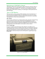
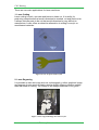
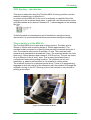
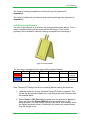
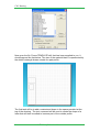
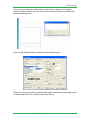
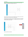
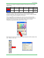
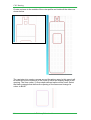
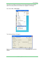
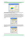
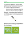
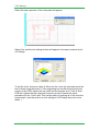
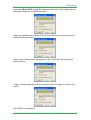
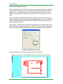
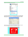
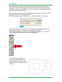
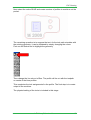
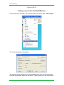
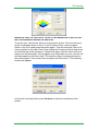
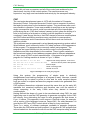
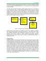
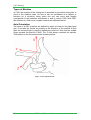
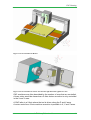
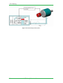
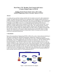
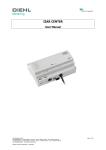
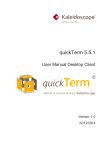
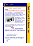
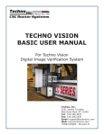
Leaving Certificate
Technology
CNC Routing & Applications
TechSoft RotoCAMM MDX-40
Contents
Applications of CAD/Cam in Schools ...................................................... 1
Types of CNC Machines ......................................................................... 1
CNC Routers/Mills .................................................................................. 3
CNC Routing – Introduction .................................................................... 9
Characteristics of the MDX-40 ................................................................ 9
Operation of the Machine........................................................................10
2D Machining..........................................................................................16
2D Machining Exercise ...........................................................................19
Projects...................................................................................................31
PCB Manufacture....................................................................................32
Designing and Manufacturing a PCB ......................................................34
Machining the PCB .................................................................................39
Appendix 1..............................................................................................46
Appendix 2..............................................................................................51
Appendix 3..............................................................................................54
Appendix 4..............................................................................................57
Appendix 5..............................................................................................58
Origins of CAD/CAM ...............................................................................65
CNC Routing
Applications of CAD/CAM in Schools
This section will first look at the types of CNC machines commonly used in a
school setting. Then, for each type of machine, an overview is given of the
range of processes possible for it. For many of the processes the starting
point will be a CAD model or drawing. The workings of CAD systems are not
discussed here.
Types of CNC Machine
There are three common types of CNC machines used in the classroom. In
each case they can greatly simplify the manufacture of an item or in many
cases permit the manufacture of an item that would otherwise be impossible.
The applications of each are described below.
CNC Lathes
These will be a familiar item to many people as they have been in Engineering
rooms in schools for many years. The most useful application is in the
production of parts that have radiused corners, tapers and threads that are
difficult to produce otherwise. Boxford and EMCO are the two most common
manufacturers and are described in more detail in a later section.
Laser Technology
Laser is a relatively new technology in the classroom and offers a very
versatile and easy means of producing items from wood and plastic materials.
The machines are very easy to set up and use (there is no need to clamp the
workpiece) and behave in much the same way as a printer or plotter. The
laser machine is driven directly from the CAD system or graphical package
being used.
Figure 1 Laser cutting machine
© t4 Galway Education Centre
1
CNC Routing
There are two main applications for laser machines:
1. Laser Cutting
Laser cutting is quick, accurate and leaves a clean cut. It is useful for
producing components that would otherwise be marked, cut and filed to size.
It allows intricate parts to be cut that would otherwise be very difficult to
manufacture. Laser offers an attractive alternative to milling for acrylic or
wood based materials.
Figure 2 Laser cut parts from Acrylic
2. Laser Engraving
It is possible to take an image such as a photograph or other graphical image
and engrave it onto wood or plastic using a slightly different machine setting
than that used for cutting. The quality of the image produced is very good.
Figure 3 Laser engraved image onto clear acrylic
2
© t4 Galway Education Centre
CNC Routing
CNC Routers / Mills
A router can be classed as a type of milling machine that allows very fast
cutter travel combined with very high spindle speeds. However routers have a
relatively low stiffness compared with a conventional machine. These
machines are ideal for machining plastics, wood, modelling foam etc. but
usually are limited to non-ferrous metals at best due to the lack of rigidity. A
desktop router typically comes with an impressive set of software and
ancillary equipment, considering the low cost. They are extremely versatile
and can be used for a variety of purposes.
A typical machine will offer the following capabilities
2-D Profile Cutting
CNC routers can be used to machine shapes consisting of lines, arcs and
curves from sheet material. The machine is usually driven by a 2-D machining
software package such as TechSoft 2-D design. This allows the profiles of the
items to be imported from a CAD system and cut on the machine. Features
such as holes, pockets and bosses can be produced as well. The user
interface of these packages is often basic and drawing and editing of complex
shapes is best completed before exporting the data from the CAD system.
PCB Manufacture
Manufacturing a PCB from copper clad board allows versatility in Technology
projects where a pupil can design a circuit and then manufacture a PCB to fit
a particular project or application. Because there are no toxic chemicals
involved (as is the case with PCB etching) it is a very suitable process for the
classroom.
In order to manufacture the PCB a specialist PCB manufacturing software
package is used. One such package is TechSoft PCB design and make. The
PCB design is generated beforehand using software such as PCB Wizard or
Circuit Wizard and then imported into PCB Design and Make. From there it is
a relatively simple matter to machine the tracks and holes as the software
handles the details of tool offsets, cut depths, sequencing etc.
PCB Design
PCB Artwork
Machined PCB
Figure 4 Stages in PCB manufacture
© t4 Galway Education Centre
3
CNC Routing
3-D Machining
Machining of complex parts such as forms for vacuum forming, moulds and
models requires a 3-D machining software package. This differs from the 2-D
software in that it can import a three dimensional representation of the part to
be made rather than just a two dimensional profile as previously. The starting
point is to generate a solid model of the item to be made using CAD software
such as SolidWorks. This is then exported into the 3-D software where
toolpaths are generated for both the roughing and finishing of the item. The
software is often wizard based and leads the user through a series of logical
steps through the process of preparing the machining sequence. Graphical
simulation of the toolpath allows a realistic preview of the part to be
generated. 3-D machining is one of the most powerful features of the desktop
router and should contribute significantly to the development of Technology
projects.
Figure 5 CAD model of part
Figure 6 Model of part showing toolpath
4
© t4 Galway Education Centre
CNC Routing
Figure 7 Machined part
3-D Scanning
In 3-D scanning an existing component can be reverse engineered by using a
touch probe to capture a grid of points on its surface and store them as a CAD
model. This is particularly useful where an existing complex part exists that
needs to be copied or have something machined or engraved onto its surface.
The way of making a 3-D scan is not very different from using a 2-D scanner
to scan a document. The main difference is the third dimension. In a
conventional scan, the area of the page to be scanned is defined before
performing the scan. With 3-D scanning, it is necessary to define a box
around the volume to be scanned in the X, Y and Z directions. This is easily
done once the size and position of the item on the machine table is known.
One important issue with 3-D scanning is the usability of the file once it is
imported into the CAD system. Often the amount of editing that can be done
to the CAD model is limited, particularly in systems such as SolidWorks that
are based on parametric design. However for simple applications such as with
engraving packages the scanned file is perfectly acceptable.
Figure 8 Touch probe and part to be scanned
© t4 Galway Education Centre
5
CNC Routing
Figure 9. The default scanning volume is the entire motion envelope of the machine
Figure 10 Small envelope confining scanning to the volume of the component
6
© t4 Galway Education Centre
CNC Routing
Engraving, Carving, Lithopane Machining.
These processes may be less familiar than the more common applications for
routers but offer a wide range of opportunities in the classroom. They all share
one thing in common. They involve taking a 2-D object such as a photograph
or profile and giving it a third dimension. This ‘3-D’ object is then projected
onto a surface or a plane (depending on the application) and then machined
into it. In each case a specialist software application is needed. These
engraving software systems are usually limited in what they do (e.g.
engraving only) due to the degree of specialism involved. However they are
easy to use and can produce spectacular results. Each is discussed in more
detail below.
Engraving
Engraving is a means of creating reliefs (raised engravings) and engravings
on flat and curved surfaces. Items such as text or a 2-D profile are given a
thickness and then projected onto the surface of the object to be machined.
Items such as text or line drawings are commonly used to make engravings.
Engravings can be made on existing solid objects if the surface of the object
to be engraved can be captured using a 3-D scanner (see above) beforehand.
Images can also be engraved onto surfaces generated in CAD.
Figure 11 Relief on a curved surface
Lithopane Machining
A Lithopane is a special form of image where a greyscale can be reproduced
by machining a translucent material to varying depths. The deeper the cut, the
thinner the remaining material and the more light that can pass through it. By
varying the depth of cut lighter and darker areas can be produced. When lit
from behind the image is visible. High quality monochrome images can be
produced in this way.
© t4 Galway Education Centre
7
CNC Routing
Figure 12 Lithopane machined from translucent plastic back-lit and mounted in a frame
Lithopane machining is very easy to do using the specialist software
accompanying Denford and TechSoft routers. It involves taking a scanned
image or digital photograph, converting it to a greyscale, projecting it onto a
plane and letting the software generate the cut depths and toolpath.
1.1
1.2
1.3
Bitmap image
Converted to 3-D surface
Machined Lithopane
Figure 13 Stages in the production of a lithopane image
Production of a lithopane is very easy and quick and is expedited by a
‘Wizard’ that moves through the process step by step.
8
© t4 Galway Education Centre
CNC Routing
CNC Routing – Introduction
This section deals with using the TechSoft MDX 40 routing machine and the
material contained here is specific to it.
In order to set the MDX-40 up for use it is necessary to carefully follow the
steps given in the machine setup guide. In particular, the Roland printer driver
must be installed and a shortcut created to it. It should appear on the desktop
like this:
TechSoft provide a comprehensive set of tutorials for using the various
options and it is recommended that these are worked through thoroughly.
Characteristics of the MDX 40
The TechSoft MDX-40 is a three axis routing machine. The table area is
305mm x 305mm with a working height of 100mm approximately. The
machine head is mounted on a gantry which provides movement along the X
axis. The machine table moves to provide a Y axis. The head can travel
upwards and downwards to provide the Z axis. The machine spindle can hold
tools up to 4.5mm diameter and rotates at 15,000 rev/min. The tool can travel
at up to 50mm/s in the X and Y axes. This is many times faster than a
conventional metal cutting milling machine. The machine can cut soft
materials e.g. plastics and wood but is not suitable for cutting metal.
The machine is driven by a windows printer driver. There is no programming
language to deal with and all of the interaction with the machine is through the
software running on the PC. Running a job on the machine is very similar to
printing a document.
Figure 14 TechSoft MDX 40 Router
© t4 Galway Education Centre
9
CNC Routing
Operation of the Machine
The machine console offers a basic set of controls that are used to switch the
machine on and position the tool for setting it up. The rest is controlled from
the computer via the printer driver.
The control panel looks like this:
Figure 15 Control panel of MDX 40
The important controls are described below:
Power on/off button
When powered on, the machine moves to a datum point and then parks the
tool. It is then ready for use. Note that the machine needs to be powered on
so that the computer can see it.
View Button
When pressed, this interrupts whatever is going on, moves the tool clear of
the work and moves the table to a forward position where it can easily be
seen. Once the table and tool have parked, the guard can be opened and the
part inspected. Pressing the view button again resumes the machining where
it left off. The green LED lights up when a view is in progress. It is not possible
to do anything else with the machine until the view is cancelled.
Z Axis Jog Button
This is used to adjust the height of the spindle when setting up a tool. The
axis moves slowly at first and then more quickly as the button is held.
Emergency Stop
This is self explanatory. It is the simplest way to bail out of a program in a
hurry. The machine will need to be powered on again afterwards to reset it.
There are three main aspects to using the CNC routing machine. These are:
• Workholding and operation of the machine.
• Toolsetting
• Programming
• Workholding and Toolsetting are common to all tasks so they are
considered first.
10
© t4 Galway Education Centre
CNC Routing
Workholding
The method used to secure the workpiece to the machine table will vary
depending on the type of material being cut and the shape of the job itself.
For all tasks it is useful to fit a 4mm thick sheet of acrylic or similar over the
machine table and then machine it flat. This has two advantages
• It provides a true flat surface for mounting the workpiece
• It can act as a sacrificial surface that can be machined into if needed
without affecting the machine table
TechSoft provide a sheet of material cut to the correct size and a program
ready to machine it. It is strongly recommended that this is done before
anything else.
Once the table is set up, workpieces that are not porous can be fixed to the
machine table using double sided tape. This is ideal for PCB manufacture and
for the machining of acrylic. It also has the advantage of offering no obstacles
for the tool to collide with during machining. The tape used is a special grade
that peels cleanly from the workpiece afterward and is supplied by TechSoft.
The double sided tape available in stationery shops leaves a residue that can
be cleaned using a solvent such as paint thinners.
For workpieces that are not suitable for tape, a vice can be taped to the
machine table and used as normal. However, more care must be taken to
ensure that the tool does not interfere with the vice.
A third option available on TechSoft machines is the self-centering vice. This
is described in more detail in the section on 3D machining.
The datum for most operations will be the bottom left of the machine table as
one looks in from the front of the machine so most workpieces are mounted
accordingly. However, it is a simple matter to set the datum point to
anywhere else if needed.
Figure 16 View of the machine table
© t4 Galway Education Centre
11
CNC Routing
Toolsetting on the MDX-40
The machine offers a simple and user friendly means of setting up cutting
tools. Before looking at this it is necessary to understand the issues involved.
Machine Datum Points
When first powered up, the machine seeks a homing point on the X, Y and Z
axes. This provides an accurate and repeatable means of zeroing each of the
axes and means that even if the machine is powered down, it will be able to
resume work on a partly machined item. The machine zero point is located
near the bottom left of the table for the X and Y axes and near the highest
point of its travel for the Z.
Figure 17 Machine Zero point
Tool Length Offsets
It is common to use the top of the workpiece as the datum for the Z axis. i.e.
Z=0 for the top surface of the billet.
Figure 18 Location of the Z axis datum
12
© t4 Galway Education Centre
CNC Routing
This is obviously not the same as the machine zero. Furthermore, when a
cutting tool is fitted, it will project down below the machine zero. The machine
will have to compensate for the gap between the tool and workpiece when
calculating where to move.
Figure 19 Gap between tool and workpiece
This is further complicated when several tools (e.g. a roughing and a finishing
tool) are used as they may have different lengths.
Figure 20 Tools of different lengths.
Fortunately, there is a simple way to solve this problem.
With the MDX 40 all the cutting tools feature a long shank, 4.5mm in diameter
that is held top and bottom by brass collets and grubscrews. The bottom collet
secures the tool in the machine spindle and the top collet provides a means of
controlling the height of the tool. Once the top collet is set, the tool can be
removed and replaced later without losing its height setting.
© t4 Galway Education Centre
13
CNC Routing
Figure 21 Toolholding in the MDX 40
To set a tool, first the spindle is positioned in a suitable position over the
workpiece using the printer driver on the PC. This position is then set as the Z
axis zero using the interface of the print driver. Then the tool is fitted to the
spindle with the collets loose and allowed to drop until it touches the
workpiece. The top collet is then tightened to fix the height of the tool. If more
tools are required, they are fitted in the same manner and their top collets
used to retain the height setting. This has the effect of making all of the tools
exactly the same length so that they can all be used at the Z axis zero just
set.
14
© t4 Galway Education Centre
CNC Routing
For some applications such as 3-D machining, the lengths are set before
running a program using the printer driver.
Figure 22 Printer driver dialogue for tool setting
However for other applications such as PCB manufacture it is done as part of
the print dialogue when sending a program to the machine. The process will
be shown for each of the examples below.
Caution: If the tool height is incorrectly set, it is likely that it will crash
into the workpiece causing damage. If in doubt, remove the tool from
the spindle and ‘dry run’ the program beforehand to make sure.
© t4 Galway Education Centre
15
CNC Routing
2-D Machining
General Issues relating to 2-D machining
The following points apply to 2-D machining across all applications.
This type of part consists of one or more profiles, each machined at a
constant depth. Clearly a two dimensional drawing of a single profile cannot
represent the part completely and information regarding where to cut and how
deep needs to be added. As well as this, heights for clearance moves
between profiles, speeds and feeds need to be entered also. Taking this into
account, a ‘simple’ 2-D part will often be more complex to set up than a 3-D
one. Machine manufacturers tend to each take their own approach to
addressing these issues. The following section deals with the Techsoft system
only.
Main Considerations in Setting-up a 2-D Part
Consider the desk tidy project shown below:
Figure 23 Desk Tidy project
16
© t4 Galway Education Centre
CNC Routing
Figure 24 Desk Tidy before bending
Note that the roughing toolpath has been omitted for clarity in this example.
In order to produce the part accurately the tool must cut to the correct side of
the profile as shown below. To do this, the diameter of the tool must be known
beforehand. It must also move clear of the workpiece when moving from one
profile to another and move to the correct depth of cut afterwards.
Figure 25 2-D profile showing tools and offsets
As each profile is cut to a different depth these need to be set up. This is
achieved on the Techsoft machine by assigning a particular line colour to a
tool/depth combination when drawing the profiles.
Say for the above part, the Thickness of the material is 5mm, the pocket is
3mm deep and the text is engraved 0.5mm deep.
© t4 Galway Education Centre
17
CNC Routing
Figure 26 Profile showing colours assigned to different depths of cut
In this example, the profiles drawn in red are cut to the full depth of the
material thickness, the blue and green would be the depth of the pocket and
the engraved text respectively. It is usual to be able to assign different cutting
tools, speeds and feeds for a particular colour so the setup for the part above
might look something like the following:
Colour
Tool
2
Diameter
3
Depth
5mm
Feed
20mm/s
2
3
3mm
20mm/s
1
0.2
0.5mm
30mm/s
Speed
12,000
rev/min
12000
rev/min
12000
rev/min
In the above example, all profiles drawn in red are machined to a depth of
4mm using Tool No. 1 at the speeds and feeds specified. This principle will be
put into practice in the next section.
2-D Machining on the TechSoft MDX 40
TechSoft provide a software package called Design Tools – 2D Design for this
purpose. It offers a CAD-like drawing environment that allows items to be
drawn up from scratch. It also allows the setting up of tools and toolpaths as
described above. There is a comprehensive user manual outlining the
functions of all the drawing and editing tools. 2D Design is adequate for
simple shapes. For more complex designs it may be easier to use a CAD
system such as SolidWorks and then import the drawing into 2D Design for
machining.
The issue of file transfer between different software systems has been
discussed earlier.
The issues relating to setting up cutting tools and cut depths are dealt with in
Appendix 1.
18
© t4 Galway Education Centre
CNC Routing
The detail of creating toolpaths to machine the part is explained in
Appendix 2
The detail of setting the tool datums and machining the part are explained in
Appendix 3
2-D Machining Exercise
The aim of the exercise is to produce the picture holder shown below. First, a
partly complete drawing will be imported into 2D Design. Then further
geometry will be added to it before creating a toolpath and machining it.
Figure 27 Picture Holder
To save time, a predefined tool setup will be used as follows:
Colour
Tool
Diameter
Depth Depth/pass
Feed
1
2.0
3.1mm
1mm
40mm/s
1
2.0
0.5mm
1mm
40mm/s
Speed
12,000
rev/min
12000
rev/min
Start Techsoft 2D Design and do the following before starting the exercise:
1. Load the setup file ‘Frame Template Setup.CFG’ that is supplied. This
will set up the tools and depths of cut as well as the work area size and
the material blank.
2. Select Setup – CNC Devices and make sure the plot device and print
driver are set to the Roland MDX 40 print driver as shown in the
window below. This step can be ignored if the MDX 40 is already set as
the default windows printer. Otherwise it will need to be selected each
time 2D design is run.
© t4 Galway Education Centre
19
CNC Routing
Now open the file ‘Frame TEMPLATE.dtd’ that has been supplied to you. It
should appear like that below. The size of the material blank is represented by
the dotted rectangle drawn outside the part profile.
The first task will be to add a customised shape in the space provided at the
top of the drawing. The text command will be used to create the shape of a
letter that will then be edited to become part of the outside profile.
20
© t4 Galway Education Centre
CNC Routing
Zoom in close to the top of the shape allowing some space to the right to
create the letter. Select the Text command on the left toolbar to produce the
following dialogue box.
Click on the Settings button to show the following window.
Choose a font such as Arial or similar and make sure that the text height is set
to 20mm and that Fill is turned off as shown above.
© t4 Galway Education Centre
21
CNC Routing
Select Ok and then type the letter you want into the text entry box. When
finished you should have something similar to this:
The next step is to move the newly created shape into position and to edit the
drawing so that it becomes part of the outside profile.
Drag the letter into a position close to the centre of the frame and overlapping
it as shown below. It may be helpful to turn Grid Lock off before moving the
shape into position (below right).
Now the profiles can be edited.
22
© t4 Galway Education Centre
CNC Routing
The Text character has all of its entities grouped and must be exploded before
proceeding. Highlight the character and select Edit-Explode as shown.
To familiarise yourself with the commands needed to complete the exercise,
click and hold on the Line, Arc Contour and Delete buttons on the left hand
menu. This will display all the options available on each.
© t4 Galway Education Centre
23
CNC Routing
The highlighted commands will be important in completing the exercise.
Examine each and determine how it works.
To edit the shape, proceed as follows:
Switch on Attach and Radial Lock in the toolbar on the top right of the work
area and construct two horizontal lines from the bottom of the letter extending
beyond the outside profile. These will be trimmed back later.
Right Click on the Attach button and make sure the settings are set to those
shown on the next page.
24
© t4 Galway Education Centre
CNC Routing
Now start to edit the geometry. With Attach and Radial Lock on, create two
horizontal lines from the base of the letter as shown below.
Now use the Delete between intersections command to remove the
unwanted lines from the outer profile. It should now look like this.
© t4 Galway Education Centre
25
CNC Routing
Next edit the detail at the base of the letter to form a profile that can be
machined through. Delete the two lines at the base of the legs of the letter
and create a new line to form a rectangular profile between them.
Finally, add a fillet of radius of 3mm on the outside shoulders of the part.
26
© t4 Galway Education Centre
CNC Routing
The part is now ready for assigning toolpaths. Remember the tool settings
made earlier.
Colour
Tool
1
Diameter
2.0
Depth
3.1mm
Depth/pass
1mm
Feed
40mm/s
1
2.0
0.5mm
1mm
40mm/s
Speed
12,000
rev/min
12000
rev/min
Therefore the colour red must be used to create the toolpath for all the
through cut profiles. The colour blue will be used to create an additional pass
to give a recess around the aperture of the frame.
First choose RED as the drawing colour from the menu at the top of the
screen. NB Choose the red colour from the custom colours at the bottom of
the palette. This is because an exact match of the colour is needed.
Otherwise the geometry will be ignored when cutting.
Now select the contour tool and set the offset distance to half the radius of the
tool, 1.00mm in this case.
© t4 Galway Education Centre
27
CNC Routing
Create contours to the outside of the outer profile and inside all the others as
shown below.
The next step is to create a recess around the picture area. In this case it will
be sufficient for the centreline of the cutter to follow the existing shape of the
opening. The 2mm cutter / 0.5mm depth defined earlier will be used. Select
the black rectangle that defines the opening of the frame and change its
colour to BLUE
28
© t4 Galway Education Centre
CNC Routing
The part is now ready for machining. Fix the material blank to the machine
table in the same position and orientation as it appears in 2D Design.
Now, Select File – CNC Output
The following dialogue will appear:
Make sure the device and print driver are set to Roland MDX 40 and select
Output
© t4 Galway Education Centre
29
CNC Routing
The next step will involve setting the length of the tool on the machine.
MAKE SURE THAT THE TOOL IS NOT FITTED TO THE MACHINE AS IT MAY COLLIDE
WITH THE WORKPIECE DURING THE NEXT STEP
To set the tool, click on the ‘Move to tool set point’ button. The tool will
move to the coordinates shown in the X Y and Z boxes. Enter a value of about
90mm in the Z box before pressing the button. This will move the Z Axis to a
closer position to the table. Now fit the cutting tool loosely and let it drop down
to touch the top of the workpiece. Tighten the upper and lower collets. Leave
the tool in place and press the Output button. The following window will
appear.
Press continue. This will start the machining of the recess around the window
opening. At the same as this is being machined time the following window will
appear, prompting you to wait until the present machining has stopped before
fitting Tool 2.
The machine will switch off when machining is complete.
30
© t4 Galway Education Centre
CNC Routing
Projects
1. Design and make a noughts and crosses game.
2. Design and make the square/triangle/circle game.
© t4 Galway Education Centre
31
CNC Routing
PCB Manufacture
PCB manufacture is quick and easy using the Techsoft Router and PCB
Design and Make software. PCBs are made from a material known as ‘copper
clad board’ that consists of a paper based laminate material covered on one
side with a thin film of copper. The technical name for this material is FR2.
The copper can be engraved away to form tracks that make up the circuit on
PCB. The production of a PCB involves up to three operations.
•
•
•
The first is to engrave the tracks and pads using a vee engraving tool.
Once the tracks are complete, holes can be drilled in the pads to allow
the wires from the components to pass through.
The third (optional) operation is to cut the outline of the PCB to size.
A vee engraving tool typically makes a cut of about 0.3mm wide when cutting
at 0.25mm deep. This needs to be taken into account when designing a PCB
and enough space needs to be left between adjacent tracks to allow the tool
to pass between them. If the tracks or pads are made too close together then
all of the surrounding copper may not be removed. Adjustments to the PCB
are best made using the PCB design software (PCB Wizard, Circuit Wizard or
similar) beforehand.
When designing a PCB it is a good idea to make the tracks and pads and
isolation gaps as large as the size of the PCB will allow. This makes soldering
easier and reduces the chance of over soldering and short circuits. The
diagrams below show the same circuit. The PCB on the left has increased
track and isolation gap widths.
32
© t4 Galway Education Centre
CNC Routing
The parameters governing the characteristics of the PCB are chosen as
options within Circuit Wizard during the conversion from circuit diagram to
PCB.
The soldering of the PCB can be further simplified by machining away all of
the remaining copper from the board and leaving just the tracks. However
boards made this way take much longer to machine so there is a trade-off
involved.
Drilling holes on a PCB
There are a number of options for drilling the holes on a PCB. Holes are
recognised automatically and can be either spotted using the vee tool for
hand drilling later or else drilled on the router as a separate operation. If this
option is selected, then a separate toolchange will occur for each diameter
drill required.
Manufacturing a PCB using the TechSoft Router
The package used on the Techsoft is called PCB design and make. It looks
and behaves very much like 2-D design with some specialised functions to
cater for PCB manufacture. It is possible to draw up a PCB from scratch but
most people will want to use it to machine an existing design from PCB
Wizard or Circuit Wizard. If this method is chosen then there is little to be
done apart from setting up the machining area and choosing the correct size
tools.
When first run up, PCB design and make looks like this.
The environment looks a lot like 2D Design although there are some important
differences.
To set it up for use, Select Setup - Load Setup and load the T4 configuration
file. This will set the defaults for the following exercise. A detailed explanation
of how the drawing area and tools are set up is given in Appendix 4
© t4 Galway Education Centre
33
CNC Routing
Understanding Layers in PCB Design and Make
PCB design and make has a number of predefined layers similar to those
found in CAD systems. They are designated to different parts of a PCB such
as Silk screen, schematic etc. All of the tracks reside on the Solder layer.
Most of the other names are self-explanatory.
Anything drawn on the Board Profile layer will be machined to the full depth
of the board. If a rectangle is drawn (or other shape if needed) then it will be
machined as the final operation.
Layers can be switched off or on to aid clarity in the same manner as a CAD
system. The correct layers are assigned to the different parts of the PCB
automatically when a file is imported to the system.
Designing and Manufacturing a PCB
The Circuit shown below is for speed control of a motor. This exercise will
involve creating a PCB for it and then exporting and manufacturing it. First
start Circuit Wizard and load the file: Motor Speed Control.cwz
Creating a PCB
Start the process of converting the circuit by clicking on the icon at the top
right of the toolbar.
34
© t4 Galway Education Centre
CNC Routing
Click Next and select the ‘Single Sided Thick Tracks’ option as shown below.
Accept the defaults for all the following dialogues until the conversion is
complete. The PCB should now look like that shown below:
The PCB is now ready for manufacture. However if desired the placement of
the components and track widths etc can still be changed if desired.
First make sure that Interactive Routing is enabled.
© t4 Galway Education Centre
35
CNC Routing
Now drag and rotate any of the components to a different position on the PCB
(note the rotate icons are the two visible above the pull down menu in the
figure above). It should be possible to position the components so that their
layout on the PCB is similar to the circuit diagram.
Make sure that the there is adequate space between the tracks and pads for
the cutter to pass between them. If not, reposition them until a satisfactory
result is achieved.
Save the file once you are happy with the layout.
Individual tracks can be moved by clicking and dragging on the nodes at the
end of each segment. The width of a track can be changed by right clicking on
it and altering the properties.
Note that intervention such as this is usually not necessary with simple
designs such as this one but it will sometimes be necessary to reduce the
width of a track to pass underneath an IC or to re-route it around an obstacle
on the PCB with more complex designs.
Use Undo if necessary to revert to the correct design before proceeding to
next section.
36
© t4 Galway Education Centre
CNC Routing
Importing the data from Circuit Wizard to PCB Design and Make
Transferring the data between the two systems does not require the use of
Gerber files as it is possible cut and paste the design directly. Start both
applications and open the PCB design in Circuit Wizard.
Select File – CAD/CAM – Copy CAM Data. This copies the PCB design to the
clipboard.
Then switch to PCB design and make and select Edit – Paste or Ctrl –V. This
will paste the design on the centre of the work area.
The design can then be dragged to the bottom left of the machine table as
shown.
© t4 Galway Education Centre
37
CNC Routing
Create a rectangle around the board profile as follows:
Then select the correct layer using the menu at the top left of the screen
Finally, draw the rectangle where the edge of the board should be. It may be
helpful to draw the rectangle to a particular size e.g. 50x40mm using the snap
and grid and then to move it to a suitable position around the tracks as shown
below.
38
© t4 Galway Education Centre
CNC Routing
Machining the PCB
1 – Without Copper Removal
The procedure for manufacturing the PCB is identical to that of machining a 2D part. The PCB should be fixed to the front left of the table using double
sided tape. Make sure that the board is flat and level on the machine table.
Select File – Make PCB to start the process.
The window that appears next looks like its counterpart in 2-D design except
that it provides some options on how the PCB is to be made. Select Solder
Side only and make sure that Full Copper Removal is off.
© t4 Galway Education Centre
39
CNC Routing
Select Ok and a preview of the cutter path will appear.
Select Yes and the tool setting window will appear in the same manner as for
2-D Design
To set the tools, choose a value of 90mm for the z tool set point and move the
tool to there using the button. Fit the engraving tool so that it touches the top
surface of the PCB, tighten the top collet and remove the tool. Fit the 0.8mm
PCB drill, tighten the top collet and remove it as well. Repeat the same
procedure for the 1.2mm drill. This has the effect of making all of the tools the
same length ( see the section on tool setting for 2-D Design above for more
detail. )
40
© t4 Galway Education Centre
CNC Routing
Now select Make PCB to begin the machining process. Fit the engraving tool
and press continue to engrave the tracks.
When the operation has finished fit the 0.8mm PCB drill and then continue to
start the drilling operation
When this is finished a prompt appears for the 1.2mm drill. Fit the drill and
press continue.
Finally, a prompt appears to fit the engraving tool once again to cut the outer
profile.
The PCB is now complete.
© t4 Galway Education Centre
41
CNC Routing
2. With Full Copper Removal
With full copper removal, all of the copper surrounding the tracks is machined
away as well. The cutting tool traverses back and forth across the workpiece
making cuts at close intervals. As the effective diameter of the tool is just
0.3mm, this process can add several minutes on to the machining time for a
PCB.
The procedure for making a board with full copper removal is very similar to
that just explained above except that the drawing layout needs to be edited so
that the drawing area matches the size of the PCB. This puts a limit on the
area for copper removal.
Select Setup – Drawing Layout and set the board area to slightly larger than
the board size as shown below. Moving the PCB to a position near the bottom
left of the machine table will reduce the amount of material to be machined.
The board area is now resized to the same size as the PCB
42
© t4 Galway Education Centre
CNC Routing
Select File – Make PCB to start the process.
The window that appears next looks like its counterpart in 2-D design except
that it provides some options on how the PCB is to be made. Select Solder
Side only and this time make sure that Full Copper Removal is checked.
Select Ok and a preview of the cutter path will appear. This time the copper
area to be machined away appears in red between the tracks.
© t4 Galway Education Centre
43
CNC Routing
Select Yes and the tool setting window will appear in the same manner as for
before.
To set the tools, choose a value of 90mm for the z tool set point and move the
tool to there using the button. Fit the engraving tool so that it touches the top
surface of the PCB, tighten the top collet and remove the tool. Fit the 0.8mm
PCB drill, tighten the top collet and remove it as well. Repeat the same
procedure for the 1.2mm drill. This has the effect of making all of the tools the
same length (see the section on tool setting for 2-D Design above for more
detail).
Now select Make PCB to begin the machining process. Fit the engraving tool
and press continue to engrave the tracks.
When the operation has finished fit the 0.8mm PCB drill and then continue to
start the drilling operation
44
© t4 Galway Education Centre
CNC Routing
When this is finished a prompt appears for the 1.2mm drill. Fit the drill and
press continue.
Finally, a prompt appears to fit the engraving tool once again to cut the outer
profile.
The PCB is now complete.
© t4 Galway Education Centre
45
CNC Routing
Appendix 1
Using 2-D Design – Setting-up the Machine and Tools.
The setup described in the next section applies in more or less the same
format to all the 2-D software applications for the machine including
PCB manufacture.
There are three main tasks:
1. Select the machine ( i.e. the printer driver)
2. Set up the plot area to match the machine table.
3. Define and assign the cutting tools to be used.
When 2-D design is first run up the window looks like the following: The white
area in the centre corresponds to the machine table.
Figure 28 TechSoft 2-D Design
Before starting work it is best to set up the machine and tool parameters as
they will affect how the software behaves.
The first task is to set the MDX-40 as the plot device. Select Setup – CNC
Devices.
46
© t4 Galway Education Centre
CNC Routing
The following window will then appear:
Choose the RotoCAMM MDX-40 as shown. Do not press OK yet as there are
other options to be set.
Make sure that the Output Route panel shows the Roland MDX-40 printer
driver. If not, use the Change Driver button to make it the same as shown
above.
Finally, Tools and the following window will appear:
© t4 Galway Education Centre
47
CNC Routing
Setting up the tool is done in two stages. First a tool is defined using the Tool
parameters box at the bottom. As seen above, Tool No. 1 is defined in the
Tool Parameters panel with a diameter of 2mm, Max depth per pass of 1mm
and with a horizontal feedrate of 20mm/s. Change the federate to 40mm/s by
clicking on the Edit button. The settings are self explanatory.
If more than one tool is being used in a program they can be defined at this
stage.
The next stage is to set up the machining parameters for the tool. The most
important ones are the Depth of Cut and its associated colour. Different
colours are used to specify different depths of cut and several colours can be
assigned to one tool. The order of the machining operations is also set here.
In the example above one set of machining parameters is already defined and
assigned to the colour red. Add a second set by selecting the Add button and
imputing values as shown below.
Select OK and notice that that any contours drawn in Red will be machined
first followed by those in blue. Change the order by editing one of the
parameters – say the one just created – and type the required sequence in
the Machining Order box. Enter 1 to make Blue entities the first to be
machined.
48
© t4 Galway Education Centre
CNC Routing
This completes the tooling set up for the part. The setup can be saved by
clicking on the ‘Save tools’ button and choosing a filename. Select Ok until all
windows are closed to exit the process.
The final job to be done is to set up the drawing area. To do this, proceed as
follows: Select ‘Drawing – Layout’
© t4 Galway Education Centre
49
CNC Routing
Choose the ‘Set for CNC device’ option and select the MDX-40 from the drop
down list. This will automatically resize the work area to the table size of the
machine. Select ‘ok’ to close the window.
The software is now set up and ready to use.
While this may appear long and complicated, in practice setting up the tools
and machine only takes a short time.
50
© t4 Galway Education Centre
CNC Routing
Appendix 2
Importing a CAD Drawing and Setting it up for Machining
Drawings can be imported from a SolidWorks drawing sheet using .DXF
format. See the section on file conversion elsewhere in this document. In
SolidWorks select ‘File – Save As ….’ and select ‘.DXF’ as the file type. Make
a note of the file name and location and quit SolidWorks.
Start 2D Design and create a new document so that the work area is blank.
Now select File – Import File and choose ‘.DXF’ as the file type.
Locate and select the file you created earlier. Choose the following options in
the window that appears.
Once the profile is imported, select and drag it to a suitable position near the
bottom left of the machine table.
© t4 Galway Education Centre
51
CNC Routing
The next step is to assign cutting tools, offsets and depths to the profiles.
Remember that the three depth/tool combinations have already defined in
Appendix 1 and are assigned to line colours. Therefore the toolpaths need to
be created using these colours.
First we will look at the outside profile and the two holes. These are to be cut
through and so will use the colour RED
Select the drawing colour RED from the toolbar at the top of the screen.
The tool will need to cut outside of the outer profile and inside the holes so
allowance will need to be made for the diameter of the tool.
This is done using the contour tool on the left hand toolbar. This creates a
profile offset by a given amount from an existing one.
As the tool has a diameter of
2.0 mm an offset distance of
half that amount is used. When
finished, the profiles should look
like this.
52
© t4 Galway Education Centre
CNC Routing
Next select the colour BLUE and create a series of profiles to machine out the
pocket.
The remaining operation is to engrave the text. As the tool path coincides with
the existing geometry, it can be obtained by simply changing the colour.
First use the Select tool to highlight the geometry
Then change the line colour to Blue. The profile will be cut with the toolpath
on centre of the blue profiles.
This completes the tool assignments for the profile. The final step is to create
output to the machine.
The physical setting of the tools is included in this stage.
© t4 Galway Education Centre
53
CNC Routing
Appendix 3
Cutting a part on the TechSoft Machine
Fit the workpiece material to the machine table and Select File – CNC Output
The following dialogue will appear:
The buttons provide access to the same settings that were set up at the start.
As these are already taken care of, select Tools to move on to the tool setting.
54
© t4 Galway Education Centre
CNC Routing
MAKE SURE THAT THE TOOL IS NOT FITTED TO THE MACHINE AS IT MAY COLLIDE
WITH THE WORKPIECE DURING THE NEXT STEP
To set the tool, click on the ‘Move to tool set point’ button. The tool will move
to the coordinates shown in the X Y and Z boxes. Enter a value of about
90mm in the Z box and press the button again. This will move the Z Axis to a
closer position to the table. Now fit the cutting tool loosely and let it drop down
to touch the top of the workpiece. Tighten the upper collet so that it acts as a
stop to set the tool length. If the program uses more than one tool, remove the
tool and repeat for the other tools. This has the effect of setting both tools to
the same length. Fit the correct tool and press the Plot button. The following
window will appear.
As the tool is already fitted, press Continue to start the machining of the
pocket.
© t4 Galway Education Centre
55
CNC Routing
At the same time the following window will appear, prompting you to wait until
the present machining has stopped before fitting Tool 1.
When the pocket is complete, press Continue again (tool 1 is already fitted
from the last operation) to start the machining of the outer profile.
And so on until the machining is complete.
56
© t4 Galway Education Centre
CNC Routing
Appendix 4
Setting up the PCB Design and Make for use
The procedure for setting up the plot area and cutting tools is very similar to
that described in detail earlier for the 2-D design system.
• Choose Setup – Drawing – Layout to set the plot area to match that of
the MDX 40 ( 305mm x 305mm)
•
Choose Setup – Plotting devices to choose the MDX 40 as the
plotting device and set the Connection to the correct print driver as
before.
Click on the ‘pens / tools’ button to show the following window. There are a
number of items of interest here.
Notice that the engraving tool is already defined as are the board thickness
and the clearance height for rapid moves. The spot depth is the depth used
by the vee engraving tool to spot drill the holes in the pads.
If the holes need to be drilled (as would normally be the case) then one or
more drills need to be selected to match the diameter. Assuming that the PCB
contained pads with holes of 0.8mm diameter the following setting would be
made. All holes 0.8mm diameter will be recognised and drilled as a second
operation. If holes of other diameters exist, they will be ignored.
© t4 Galway Education Centre
57
CNC Routing
Appendix 5
File Transfer between Different Systems
All CAD and CAD/CAM systems differ in how they work and how they
represent the drawing or part being modelled. For example, a 2-D CAD
system will be concerned with lines, arcs, and their start and endpoints. A
solid modelling system will need to deal with features such as extrusions/cuts
and a design tree. A PCB design package will have information on tracks,
pads and component values. All of these systems need to save their work to
disk for later use.
As these systems have developed over time, each will have devised a file
format that is most efficient for their particular needs. The format used will be
specific to the type of information being stored e.g. lines/arcs and will typically
use the least space on disk and load quickly when opened.
Native and Neutral File Formats.
It is not surprising therefore that a wide variety of file formats exist for saving
CAD/CAM data. Neither is it surprising that each filetype can usually only be
read by the application it was designed for. ( there are a small number of
exceptions )
A list of commonly used file types are shown below. There are many more.
Application
AutoCAD Drawing
SolidWorks Part
SolidWorks Drawing
TechSoft 2-D Design
Circuit Wizard
TechSoft PCB design and make
Filename Extension
.DWG
.SLDPRT
.SLDDRW
.DTD
.CWZ
.DTB
If a particular system was to be able to read in the files from another then it
would need to incorporate a routine to read, decode and convert the data
stored within it. To read data from a variety of systems then a similar routine
would be needed for each. It is easy to see that this would quickly become
impractical if many file formats were to be supported.
58
© t4 Galway Education Centre
CNC Routing
System
A
System
D
System
B
System
E
System
C
System
F
The partially complete diagram above gives an idea of this. Each of the
arrows represents a conversion routine to another file format.
To further complicate matters, software manufacturers rarely publish the
format of their native file formats and in any case they are prone to revision
without notice as the software is updated and developed.
In practice, a neutral file format is usually used to transfer data from one
system to another. The file format is published and understood by all.
© t4 Galway Education Centre
59
CNC Routing
System
A
System
B
System
D
Neutral
file
format
System
C
System
E
System
F
It can be seen that this arrangement is much simpler. Each software package
needs only one translation routine to import from and to export to the neutral
file format. To convert data from any system to any of the others, a file is
exported in the neutral format and imported by the receiving system.
The neutral file format itself will by its nature be a compromise and there will
often be some loss of system specific information (e.g. the design tree in
SolidWorks) in the translation. However this does not pose a problem as
these features are often not needed by the system subsequently reading the
file, for example a machining program such as Visual Toolpath is only
interested in the physical shape of the solid.
A few different neutral file formats have evolved over time, each with its
particular strengths and applications. These are explained briefly below.
60
© t4 Galway Education Centre
CNC Routing
Drawing eXchange Format (DXF)
DXF was originally developed by Autodesk, the writers of AutoCAD as a
neutral format for exporting and importing 2-D AutoCAD drawings. Although it
supports 3-D, it is normally used for the transfer of 2-D graphical files between
systems. It represents the items as lines, arcs, points, etc along with their
coordinate data:
ENTITIES
0
LINE
5
27
100
AcDbEntity
8
0
6
CONTINUOUS
62
1
100
AcDbLine
10
128.6588971478
20
123.3424833098
30
0.0
11
Advantages:
It is supported by most 2-D graphical programs as well as the drawing editor
in SolidWorks. DXF files are accurate to six decimal places and so are
suitable where accurately produced parts are required.
Uses:
DXF is best used in the following situations:
• Exporting a SolidWorks drawing for 2-D machining
• Exporting a SolidWorks drawing for laser cutting
Limitations:
• The way DXF files represent text means that it will usually not be read
by the system importing the file and text will often disappear altogether.
• DXF files are not suited for transferring drawings containing bitmaps or
similar raster images.
In most software, DXF file creation is available as an option under either File
– Export or File – Save As… and selecting the correct file type
© t4 Galway Education Centre
61
CNC Routing
DXF files are imported similarly by using File – Open or File – Import
Sterolithography Files (STL files)
This file format was originally developed for transferring data between CAD
systems and rapid prototyping (Stereolithography) systems. It is commonly
used to transfer the physical shape of a solid modelled component from one
system to another e.g. from SolidWorks to a 3-D Machining program for
generating toolpath.
Figure 29 SolidWorks model of a part and its STL representation
In STL, the shape of the item is represented by a series of triangles that
approximate its outer surface. The format can also show which side is the
‘inside’ and the ‘outside’ of the part. The accuracy of the shape can be
controlled by increasing or decreasing the number of triangles but in general
this is not necessary.
Advantages:
This is a quick and simple way of exporting a complex 3-D solid modelled
shape to another system.
62
© t4 Galway Education Centre
CNC Routing
Uses:
Export of a 3-D solid modelled part to another system for machining (or rapid
prototyping)
Limitations:
• All of the design and other information ( colour, texture etc ) are lost so
this is not suitable for export to another CAD system for example that
may want to use this data.
• It is not suitable for exporting/importing anything other than solid
models
Windows Metafiles
These are the files that are created when items are cut and pasted using
normal windows commands ( Edit – Cut/Copy and Edit – Paste). Entities can
be copied from one program and pasted into another. In some cases this is
the only possible way to export/import between different software, and in
many cases it greatly simplifies the process. There are some limitations
however.
Advantages:
Allows the cutting and pasting of a wide variety of data such as text, pictures
of all types, CAD drawings, across widely different software. For example a 2D CAD drawing can be pasted directly into a word document, or into another
CAD program or into an image editing program such as Paint in exactly the
same manner.
Uses:
• When exporting CAD files containing text for laser cutting
• When exporting CAD files containing 2-D profiles for laser cutting (
DXF preferred )
• When exporting raster images for laser engraving
Limitations:
• All the items are transferred using integer arithmetic and will appear as
a ‘picture’ object when they have been pasted. This means that there is
likely to be some loss of accuracy. It is usual to have to resize the
pasted item back to its original size before processing.
• Effectively limited to any item that can be represented as a picture i.e.
2-D profiles, PCB layouts, raster images etc., not 3-D entities such as
CAD models.
Gerber Files
Gerber Files resemble CNC programs in appearance and this gives some
clue to their origin. They were originally developed to drive the Gerber
Photoplotting machines that were used in producing masks for PCB
manufacture. Gerber files can contain all of the manufacturing information
relating to a PCB. Gerber files are usually generated in a set from a PCB
design package, each file defining one aspect of the PCB. For example, one
file will contain the details of the tracks ( solder side ) and another the sizes
and layout of the components ( component side ), yet another the drill holes,
© t4 Galway Education Centre
63
CNC Routing
and so on. The files are generated automatically using File-Save As… or File
– Export option from the PCB design package.
PCB manufacturing programs are able to read Gerber files directly so this
provides an easy means of transferring data from one system to another.
Uses:
Export PCB manufacturing data from CAD to CAM
Advantages
A well established and easy way to convert specialised data for PCB
Allows filtering out of unwanted items by ignoring certain files e.g. component
side.
Limitations.
Useful for PCB manufacture only.
With additional software, board outline and component shapes can be
exported to CAD but only as 2-D profiles so it is generally not worth the
trouble
64
© t4 Galway Education Centre
CNC Routing
Origins of CAD/CAM
Introduction
The term CAD/CAM stands for Computer Aided Design and Computer Aided
Manufacture. The two are often used together to describe a process where an
artefact is designed electronically using a CAD system such as SolidWorks or
AutoCAD with the information from the CAD drawing being used to
manufacture the component directly using computer controlled equipment
such as a milling machine or lathe. Over time, both CAD and CAM have
evolved separately and the seamless combination of the two is a relatively
recent development.
This module will assume a working knowledge of CAD and will concentrate on
the manufacturing aspects of the process. There is a variety of CNC machine
configurations, manufacturers and an even greater variety of processes
available to the Technology teacher. It would be beyond the scope of this
document to give a comprehensive treatment of each machine, each process
and its associated software application. Instead, a general overview is given
of what is possible and how this may be achieved. Then a machine specific
example of each is presented with enough detail for it to be replicated in the
classroom. In addition to this, a brief summary of the development of
CAD/CAM is given as well as a section on the principles behind CNC.
History
Computer Numerical Control
All of the manufacturing equipment used involves controlling the movement of
a cutting tool of some sort in a precise manner. Both the positional accuracy
and speed of travel are important and these need to be controlled precisely in
order to achieve the desired outcome. This control of the tool path is achieved
by Computer Numerical Control (CNC) systems built into the machine tool.
The systems have two aspects.
• How they control the motion of the cutting tool
• How they are programmed
In order to better understand how present day systems have come about it is
useful to look at the development of CNC over time.
Early Numerical Control
As early as the late 1940s as the cold war between the US and Russia
escalated, the American aerospace industry began to need complex aerofoil
shapes to cater for aircraft and missile manufacture. These shapes were very
difficult to machine by conventional processes and the first Numerical Control
(NC) milling machines were developed for this purpose. The machines had
what is known as a ‘hard wired’ control system and were capable of moving
from one point to another in a straight line only. The programs were generated
using a computer and loaded into the machine control one line at a time using
punched paper tape. The programs consisted of long lists of coordinate data
that were fed to the control, one line at a time for each move. This type of
© t4 Galway Education Centre
65
CNC Routing
control did not have a computer and all of the control was achieved by the
(hard wired) circuitry of the control system. The machines were very
expensive, very large and used almost exclusively by the aerospace industry.
CNC
The next major development came in 1975 with the advent of Computer
Numerical Control. Computer Numerical Control uses a computer to perform
the tasks formerly done by the hardwired system. They machines were much
more flexible in operation. It was now possible to machine an arc by issuing a
single command as the control could now calculate all of the intermediate
points along the arc. CNC also featured ‘canned cycles’ where the drilling of a
hole (or the cutting of a thread on a lathe) could be simplified to a single
command. It was around this time, that CNC started to become commonplace
and CNC lathes and Milling machines were used both to mass produce
simple components and to manufacture difficult items such as cavities for
injection moulds.
The machines were programmed by a text based programming system called
Word Address, more commonly known ‘G-Codes’ because of the appearance
of the program. The programs are commonly called ‘part programs’. The
programs are keyed directly into the machine control or else generated
elsewhere and then downloaded to the machine. There is some variation in
the format and syntax of word address programs due to different adaptations
of it by a range of CNC control manufacturers. A fragment of a typical part
program for a milling machine is shown in Figure 30 below
N5 G00 G90 X100.0 Y0.0 T1 M06
Rapid to tool change position. Load Tool 1
N10 G43 X5.0 Y-5.0 Z1.0 S1200 M03 M08
Move to start of profile. Start spindle
N15 G01 G41 Z-5.0 F100
Feed to depth
N20 X90.0
Linear cut along profile
N25 G03 X100.0 Y10.0 I0.0 J10.0
Circular arc move
Figure 30 Sample of a G-Code part program
Using this system, the programming of simple parts is relatively
straightforward and making changes to a program is easy. However, manual
programming by its nature is prone to error and for more complex shapes
such as curved or sculpted surfaces the program needs to be generated from
a CAD system.
CAD systems themselves originated around the same time as the early NC
machines but remained expensive and therefore rare until the advent of
cheap computing in the early 1980s when they started to become
commonplace.
Having defined the shape of a part to be manufactured using CAD, the next
logical step was to use the CAD geometry to generate a program for the CNC
tool directly, thus eliminating the need to write programs like that shown in
Figure 30 above. This approach is still common. Denford routers, for example,
use a version of the language known as Fanuc-OM. ( So called because it is
used by the GE Fanuc CNC control which is fitted to many machines)
There is a variety of software packages available to generate programs.
These take the CAD data and ‘post process’ it to produce a CNC program that
is then loaded into the machine control from the CAD computer using a cable.
66
© t4 Galway Education Centre
CNC Routing
This type of software combined with the CNC is commonly referred to a CAM
system. (Computer Aided Manufacture). The entire process is usually referred
to as CAD/CAM
The two most important functions a CAM program performs is to first add in
extra information that the CAD drawing would not have such as cutting
speeds, feeds, clearance moves, tool offsets etc. It then generates a G-Code
program in the correct format for the machine it is being sent to. These
programs are often very long (several thousand lines) as they are commonly
used to machine items such as mould cavities where many short moves are
required. The process is shown in Figure 31
CAD
Surface or
Solid model
CAM
Add in
tooling and
other
machining
information
Generate
Part
Program
CNC
machine
tool
Figure 31 Schematic of the CAD/CAM process
CAM systems usually offer some means to preview the toolpath or simulate
the cutting process before generating the program. They often offer a CADlike drawing functionality that eliminates or reduces the need for a CAD
system. There are a variety of CAM systems commercially available.
AlphaCAM is one system that is popular with the manufacturing industry in
Ireland at present.
Present Day
With the reduction of the cost of CNC systems and computing a variety of light
desktop machines have emerged in recent years. These were originally aimed
at the modelmaking industry and offered a low cost alternative for the cutting
of soft materials such as wood and plastic. These machines often share many
of the characteristics of a printer and offer a graphical programming system
where the user has little or no need to interact with the programming language
used by the machine. Unlike the complex user interfaces seen on full size
CNC machine tools, these machines usually offer two or three buttons to
perform the essential tasks such as setting up a cutting tool. The machines
can be controlled using a printer driver or from other software on the
computer. This effectively replaces the machine interface. This method is very
simple to use and has been adopted widely in schools for routing machines,
vinyl cutters, laser cutting etc.
© t4 Galway Education Centre
67
CNC Routing
Types of Machine
In CNC, the location of the cutting tool is specified by its position along two or
more of the machine axes. An axis is can be considered as a degree of
freedom (or a direction) along which the tool can move and roughly
corresponds to the cartesian coordinates (x and y) used in CAD. With CNC,
the situation is a little more complex however as explained below.
Axis Orientation
The axes of a CNC machine are defined by what is known as the right hand
rule. If we take the thumb as pointing in the direction of the positive X-Axis
then the second finger is pointing towards the positive Y-Axis and the middle
finger towards the positive Z-Axis. The Z Axis always contains the spindle.
This holds true for all machine tools including lathes.
Figure 32 The right hand rule
68
© t4 Galway Education Centre
CNC Routing
Figure 33 Axis orientation for Router
Figure 34 Axis orientation for Lathe. Note that the right hand rule applies here also.
CNC machines are often described by the number of axes that are controlled.
A laser cutter would be classed as a 2-Axis device as motion is only controlled
in the X and Y axes.
A CNC lathe is a 2-Axis where the tool is driven along the Z and X axes.
A router would be a 3-Axis machine as motion is possible in X, Y and Z axes.
© t4 Galway Education Centre
69
CNC Routing
Beyond Three Axis Control
With some machines it is possible to fit a dividing head and/or rotary table to
provide rotary motion of the workpiece. In this case the motion is considered
to be rotation about either the X, Y or Z axis. These rotary axes are usually
labelled A, B and C respectively.
Therefore it is possible for a machine to have four, five and even six axis
control. In practice more than four is rarely needed.
At least one desktop router manufacturer offers a fourth Axis dividing head.
This type of configuration allows the machining the top, sides and underside
surfaces of a component without the need to turn it over.
Figure 35 Router with a fourth rotary axis
70
© t4 Galway Education Centre
CNC Routing
Principles of a Practical CNC Control
All practical CNC systems contain three elements:
• The control
• Current Amplifiers
• Servo Motors
Figure 36 Block diagram of a CNC system
The control is the ‘brain’ of the system. The control reads the instructions from
the program and performs all of the calculations and measurements that
determine where the cutting tool should be for any given instant in time during
the run of the program. This can be a complex process using advanced
mathematical principles. The result is that the control can send signals to the
servo motors to control the axis positions up to several hundred times per
second. The type of signal sent depends on whether Open loop or Closed
loop control is used – see below.
The output from the control is usually a small voltage (typically plus or minus
five volts). In order to drive the servo motors a current amplifier is needed.
This uses the voltage signal from the control (called the demand voltage) to
control the current that powers the servo motors.
The servo motors are the final part of the system. There are two types
commonly used.
Stepping motors are a specialised type of motor that moves in very small
increments (steps) controlled by voltage pulses. A stepping motor typically
rotates 1.8 degrees per pulse. If 200 pulses are sent to the motor it will turn
through one complete revolution. The speed of the pulse train will control the
speed of the motor. They are usually used with Open Loop control.
The second types of motors are AC or DC servo motors. These behave in a
similar manner to a conventional AC or DC motor but are designed to provide
more constant running characteristics. These motors will exert a torque in
proportion to the current running through them. They are used with Closed
Loop control only.
© t4 Galway Education Centre
71
CNC Routing
Open and Closed Loop Control
Open Loop
This is the simplest type of control and contains the three basic elements
described in Figure 36 above.
Figure 37 Elements of an open loop control
This is shown in more detail below
The open loop system works as follows: Say that the control has calculated
that a particular axis needs to move a distance corresponding to 80 pulses at
a constant speed equivalent to 10 pulses per second. The control will output
the pulse train to achieve this which is then amplified and delivered to the
motor. The stepping motor will travel the specified number of pulses and then
hold in position until the next action. The control has no way of knowing
whether the motor has actually received or travelled the full distance. Errors
can occur if the motor misses a pulse or if it encounters an obstacle that
causes it to stall.
Figure 38 Open loop control system
72
© t4 Galway Education Centre
CNC Routing
This is not usually a problem where the forces acting on the stepping motor
are low or where extreme accuracy is not critical. The advantage of open loop
is its low cost and simplicity.
Closed Loop Control
This method of control has one additional element. Servo motors are used to
drive the axes and an encoder is used to provide feedback of the servo
position to the control. This allows the control to compare the actual position
of the axis to where it should be at a rate of about 500 times per second.
Figure 39 Elements of a closed loop control system
The control outputs a voltage in proportion to the amount of error. This voltage
controls the direction of the servo and has the effect of trying to pull it towards
its correct position. The greater the error the stronger the pull. If a particular
axis is programmed to move say,10mm at a speed of 1mm/s then it will
calculate each intermediate position for the axis in 1/500 second intervals and
then vary the demand voltage to pull the servo towards each of them over the
course of the ten seconds taken to complete the move. Once the move is
complete, if a force tries to move the axis out of position ( say a collision with
the cutting tool) the control will detect an error between the ideal and
measured positions and will try to move the axis back into position.
It can be seen that this type of control is more reliable and offers greater
accuracy than the open loop system described earlier. Closed loop systems
are used widely in CNC equipment and robotics and they are the norm in all
but the simplest systems.
© t4 Galway Education Centre
73
CNC Routing
Figure 40 A Closed loop control system
74
© t4 Galway Education Centre