1
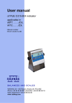
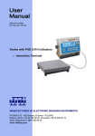
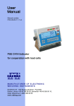
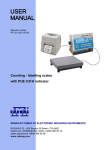
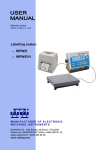
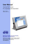
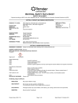
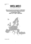
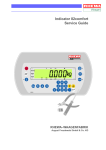
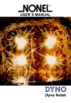
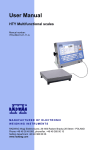
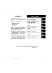
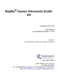
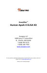
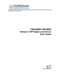
CONTENTS
PUE C/31 measuring indicators . . . . . . . . . . . . . . . . . . . . . . . . . . . . . . . . . . . . . 3
PUE C/31H measuring indicators . . . . . . . . . . . . . . . . . . . . . . . . . . . . . . . . . . . . 4
PUE C/31H/EX measuring indicators . . . . . . . . . . . . . . . . . . . . . . . . . . . . . . . . . . 5
PUE C/41H measuring indicator . . . . . . . . . . . . . . . . . . . . . . . . . . . . . . . . . . . . . 6
PUE 7 measuring indicator. . . . . . . . . . . . . . . . . . . . . . . . . . . . . . . . . . . . . . . . 7
PUE 5 measuring indicator. . . . . . . . . . . . . . . . . . . . . . . . . . . . . . . . . . . . . . . . 8
Digital modules . . . . . . . . . . . . . . . . . . . . . . . . . . . . . . . . . . . . . . . . . . . . . . 9
PUE C/31 MEASURING INDICATORS
Functions of measuring indicator series PUE C/31:
measure units: [g], [kg], [N], [ct], [lb];
tarring in whole measure range;
automatic tare, tare memory;
counting pieces with the some mass of piece;
+/- mass control of set reference mass;
per cent deviation from set reference mass;
averaging of weighing result, digital filter;
control of power supply from batteries;
timer switch off of the scale;
adjusting backlit when operating on batteries;
adjustable band rate of transmission between 2400-38400bit/s;
continuous transmission of data through RS 232;
manual or automatic mode for RS 232;
weighing loads with autozero or without;
measurement of maximal force on the weighing pan or maximal mass
placed on weighing pan;
measurement of force influencing the weighing pan (in Newtons);
control of start mass;
possibility of connecting additional LCD display;
totalizing function of measurements.
(32)
60
12
(9)
119
179
121
180,9
~136
Technical data:
Display
Keyboard
Quantity of buttons
Maximal quantity of verifying units
Maximal quantity of countings from A/C converter
Maximal increase of signal
Maximal voltage on one verifying unit
Minimal voltage on one verifying unit
Working temperature
Minimal impedance of load cell
Maximal impedance of load cell
Connection of load cells
Multi range
Excitation voltage
Interface
Aditional display
Casing
IP rating
Standard power supply
Optional power supply
Means of power supply
Average operation time on accumulators
PUE C/31
LCD
membrane
5
6000 e
838 860 × 10
19,2 mV
3,2µV
1,0µV
-10° - +40°C
80 Ω
1200 Ω
4 or 6 cables + shield
1 or 2 ranges
5V DC
RS 232
LCD (option)
ABS plastic
IP 43
230V/11V AC or 120V/11V AC and 6×NiMH AA
10-18V DC Imax=600mA
power adapter batteries NiMH 6×AA
35 h
RADWAG USA L.L.C.
19599 NE 10th Ave., Bay G, s
North Miami Beach, FL, 33179 s
USA s
Tel: 1-305-651-3522 s
Fax: 1-305-651-3523 s
e-mail: [email protected] s
website: www.radwagusa.com
PUE C/31H MEASURING INDICATORS
Functions of measuring indicator series PUE C/31H:
170
measure units: [g], [kg], [N], [ct], [lb];
tarring in whole measure range;
automatic tare, tare memory;
counting pieces with the some mass of piece;
+/- mass control of set reference mass;
per cent deviation from set reference mass;
averaging of weighing result, digital filter;
control of power supply from batteries;
timer switch off of the scale;
adjusting backlit when operating on batteries;
adjustable band rate of transmission between 2400-38400bit/s;
continuous transmission of data through RS 232;
manual or automatic mode for RS 232;
weighing loads with autozero or without;
measurement of maximal force on the weighing pan or maximal mass
placed on weighing pan;
measurement of force influencing the weighing pan (in Newtons);
control of start mass;
possibility of connecting additional LCD display;
totalizing function of measurements.
76
174
~ 250
2
17
154
100
~226
120
Technical data:
PUE C/31H
Display
Keyboard
Quantity of buttons
Maximal quantity of verifying units
Maximal quantity of countings from A/C converter
Maximal increase of signal
Maximal voltage on one verifying unit
Minimal voltage on one verifying unit
Working temperature
Minimal impedance of load cell
Maximal impedance of load cell
Connection of load cells
Multi range
Excitation voltage
Interface
Aditional display
Casing
IP rating
Standard power supply
Optional power supply
Means of power supply
Average operation time on accumulators
PUE C/31H/Z
LCD
membrane
5
6000 e
838 860 × 10
19,2 mV
3,2µV
1,0µV
-10° - +40°C
80 Ω
1200 Ω
4 or 6 cables + shield
1 or 2 ranges
5V DC
RS 232
LCD (option)
stainless steel
IP 66/67
110-120VAC 60Hz and 220-240VAC 50Hz and SLA 6V/3,4Ah
230V/11V or 120V/11V AC and SLA 6V/3,4Ah
10-18V DC Imax=600mA
power supply cable built in get cell SLA accumulator
power adapter for charging battery built in SLA battery
45 h
RADWAG USA L.L.C.
19599 NE 10th Ave., Bay G, s
North Miami Beach, FL, 33179 s
USA s
Tel: 1-305-651-3522 s
Fax: 1-305-651-3523 s
e-mail: [email protected] s
website: www.radwagusa.com
PUE C/31H/EX MEASURING INDICATORS
Measuring indicator series PUE C/31H/EX and scales constructed on its basis cab be
utilized in expolsive zones 1 and 2 of mixtures of gases, vapours and fogs with air, which are
included in exposive group II and temperature classes T1, T2, T3, T4.
Safety of measuring indicator and scales using PUE C31H/EX is guaranteed by such
means as:
- power supply of the indicator from power adapter ZRi02 II (2) G [EEx ib] IIC 06ATEX251
manufactured by RADWAG, and situated outside expolsive zone or another power
adapter with parameters adequate for spark secured circuit.
- spark secured casing of measuring indicator series PUE C31/H/EX, being in conformity
with norms: PN-EN 50014 and PN-EN 50020 and confirmed by a certificate KDB
06ATEX250
- application of transducers with exposive safety certificates
- manufacturing of the indicator according to requirements of a norm PN-EN 13463-1 on
non-electrical elements of a scale
- user obligation to obey safety precautions as indicated in the user manual of the
measuring indicator
CAUTION:
Scale equipped with a measuring indiocator series PUE C/31H/EX are fed from power
adapter ZRi02 II (2) G [EEx ib] IIC 06ATEX251 manufactured by RADWAG, situated
outside the explosive zone or another power adapter with parameters adequate for spark
secured circuit.
170
76
174
~ 250
2
17
154
100
~226
120
Technical data:
Display
Keyboard
Quantity of buttons
Maximal quantity of verifying units
Maximal quantity of countings from A/C converter
Maximal increase of signal
Maximal voltage on one verifying unit
Minimal voltage on one verifying unit
Working temperature
Minimal impedance of load cell
Maximal impedance of load cell
Connection of load cells
Multi range
Casing
IP rating
Power supply
Symbol
PUE C/31H/EX
LCD
microswitch
5
6000 e
8388608
19,5 mV
3,25 µV
1,0 µV
-10° - +40 °C
125 Ω
1200 Ω
4 or 6 cables + shield
1 or multi-ranges
stainless steel
IP 66/67
power adapter ZRi02 II (2) G [EEx ib] IIC
II 2 G EEx ib IIC T4 KDB 06ATEX250
RADWAG USA L.L.C.
19599 NE 10th Ave., Bay G, s
North Miami Beach, FL, 33179 s
USA s
Tel: 1-305-651-3522 s
Fax: 1-305-651-3523 s
e-mail: [email protected] s
website: www.radwagusa.com
PUE C41H MEASURING INDICATORS
Basic functions of indicator series PUE C41H:
92
165
~ 200
240
Measuring units: [g], [kg], [N], [ct], [lb], [oz];
Automatic dosing: single and dual threshold;
Creation of mixtures according to set formulation;
Tarring in whole measuring range;
Automatic tare, tare memory, manual insertion of tare mass;
+/- control with reference to standard mass;
Percent deviation with reference to standard mass;
Averaging of weighing result, digital filter;
Control of Power Supply from batteries; Backlit adjustment while
supplying from battery; Timer switch off;
Adjustable speed of transmission in range between 1200-115200bit/s;
Continuous transmission of data by RS 232;
Manual or automatic mode for RS 232; Weighing loads with switched off
autozero function;
Measurement of maximal force influencing the weighing platform;
Measurement of force influencing the weighing platform in Newtons;
Control of starting mass;
Possibility of connecting additional LCD display;
Summing of weighing.
Modular construction (depending on needs, electronic set can be
extender by additional modules installed inside the indicator casing):
analog modules (AN 0-10V, AN 4-20mA, AN 0-20mA), additional relay
modules (PK 1), additional A/C relay module (DP 1), in/out module(WE
8, WE 4), RS 485 module (RS 1D) and Ethernet module (ET 1G, ET 1D).
210
100
~295
120
Technical data:
Display type
Casing
Keyboard type
Power Supply
Data base size of the indicator
Maximal quantity of divisions from converter
OIML class
Quantity of verifying units
Maximal increase of signal
Maximal voltage on 1 verifying unit
Minimal voltage on 1 verifying unit
Minimal impedance of load cell
Maximal impedance of load cell
Power voltage of load cell
Connection of load cells
Working temperature
IP rating
Optoinsulated interfaces
Inputs / outputs
Input / output module
Ethernet module
Analog output module
Relay module
Additional weighing platform module
PUE C41H
LCD
stainless steel
membrane
85-265V AC 50/60 Hz, battery 6V 3Ah – operation time up to 9 h (buffer power supply)
total memory size for data base: 4 MB
8 388 608
III
6 000
19mV
3,3 µV
1µV
90 Ω
1200 Ω
5V
4 or 6 cables + screen
-10°C ÷ +40°C
IP 66/67
- (standard)
RS 232 & RS 485
- (standard)
3 optoinsulated inputs, 3 optoinsulated outputs;
- (option)
possibility of installing external PRINT and TARA buttons
- (option)
4 optoinsulated inputs, 4 optoinsulated outputs
- (option)
8 reed relay outputs, 8 reed relay inputs
- (option)
compatible with standard 10/100Mbit/s
- (option)
operation mode – 4-20mA, 0-20mA, 0-10V
- (option)
4 relays with short circuiting switch
- (option)
metrological parameters as in main platform
RADWAG USA L.L.C.
19599 NE 10th Ave., Bay G, s
North Miami Beach, FL, 33179 s
USA s
Tel: 1-305-651-3522 s
Fax: 1-305-651-3523 s
e-mail: [email protected] s
website: www.radwagusa.com
PUE 7 MEASURING INDICATOR
PUE 7 weighing indicators are intended for building industrial scales.
It can be enclosed in a plastic or stainless steel housing for rack
installations. It is equipped with a 5.7” colour graphic display with
touch panel and membrane keypad. It also has installed two proximity
detectors with programmable functionality.
Two platforms can be connected to the indicator. As regards
peripherals, following devices can be connected: barcode scanners,
receipt and label printers, transponder card readers and typical PC
equipment (keybord, mouse etc.).
Software:
standard,
counting pieces with labelling,
dosage with recipes,
KTP (CPG) for prepackages.
71
18°
"
"
5,7
138,4
156
5,7
140
~120
215
67
206
Infrared proximity sensors
Interface communication
Optional functions:
- PRINT function
- TARE function
- sensor's sensitivity adjustment
Ethernet RS 232 2×USB power supply RS 232
4in/4out
Technical data:
Housing
IP rating
Proximity sensors
Power supply
Display
Keypad
Operation Temperature
OIML class
Maximum number of verification intervals
Maximum input signal increase
Maximum voltage per verification interval
Minimum voltage per verification interval
Minimum tensometer impedance
Maximum tensometer impedance
Tensometer bridge excitation voltage
Processor
Memory
Operation System
Number of platforms
Additional weighing platform module
Interfaces
PUE 7
PUE 7/P (panel)
plastic
stainless steel
IP 54
front IP 66/67, whole IP 32
2
120÷230VAC; 10÷15VDC
10÷15VDC
5,7" with touch panel
8 keys
-10°C ÷ 40°C
III
6 000
19,5 mV
3,25 µV
0,5 µV
80
1200
5V
ARM 200 MHz
RAM 64 MB, Flash 1 GB
Windows CE 6.0
2
Metrological parameters as in main platform (option)
2×RS 232, 2×USB, Ethernet, 4in / 4out
RADWAG USA L.L.C.
19599 NE 10th Ave., Bay G, s
North Miami Beach, FL, 33179 s
USA s
Tel: 1-305-651-3522 s
Fax: 1-305-651-3523 s
e-mail: [email protected] s
website: www.radwagusa.com
PUE 5 MEASURING INDICATORS
Measuring indicator PUE 5 is suitable for scales with maximal
resolution 6000e.
Measuring indicator in stainless steel casing with 12" touch
screen. Power supply 88-264 V AC, 50-60 Hz in standard RS
232C, RS485 and Ethernet connection, USB 2.0×2, 4 in/ 4
out.
Load cell supply +5V.
410
350
110
55
162
297
270
4×18° 10×18°
120
282
min. 210
(z podłączonymi przewodami)
4×ø9
po wyjęciu nóżek
Technical data:
Casing
IP rating
Screen
Power supply
Power supply of external devices
Working temperature
Maximal quantity of divisions from converter
OIML Class
Maximal quantity of verifying units
Maximal increase of signal
Maximal voltage on 1 verifying unit
Minimal voltage on 1 verifying unit
Minimal impedance of load cell
Maximal impedance of load cell
Power voltage of load cell
Connection of load cells
Procesor
Chipset
RAM memory
Data memory
Graphic card memory
Ethernet
Optoinsulated interfaces
USB interface
In/out
Optional equipment:
Additional weighing platform module
In/out modul
Profibus DP V1 interface
PUE 5
stainless steel
IP67
LCD 12,1" (800×600) touch screen
88-264 VAC 50-60Hz
2×5 V 500 mA
work: 0°C ÷ +40°C, storage: -20°C ÷ +60°C
8 388 608
III
6 000
19 mV
3,3 µV
1 µV
90 Ω
1200 Ω
5V
4 or 6 cables + screen
Celeron M 800MHz
INTEL 855GME
DDR 512MB
HDD 40GB or Flash Disk
max. 64MB
10/100 Mbps
RS 232C, RS 485
2 × USB 2.0 (max. intensity 500mA)
4 in, 4 out
metrological parameters as In main platform
additional 8 in/out
slave working mode
RADWAG USA L.L.C.
19599 NE 10th Ave., Bay G, s
North Miami Beach, FL, 33179 s
USA s
Tel: 1-305-651-3522 s
Fax: 1-305-651-3523 s
e-mail: [email protected] s
website: www.radwagusa.com
DIGITAL MODULES
Application and functions of digital modules:
measuring units [g], [kg], [t];
tarring in all measuring range;
changeable speed of transmission between 9600-57600bit/s;
possibility of addressing;
restoring default setting by putting on the jumper;
extended communicational protocol;
protection against access to factory parameters (jumper).
Digital modules are applicable in extended weighing systems
connected in network by RS485 and controlled by a supervising
computer (system):
Pn
MCn
P1, P2,... Pn
MC1, MC2,... Mcn
K
P2
MC2
P1
K
MC1
- weighing platforms with 1 or 4 load cells
(minimal resistance of load cells 90 Ω
)
- digital module
- PC computer
Technical data:
Maximal resolution
Maximal quantity of divisions from converter
Speed of processing
Maximal increase of signal
Minimal voltage per verifying unit
Working temperature
Minimal resistance of load cells
Maximal resistance of load cells
Connection of load cells
Power consumption
Voltage on load cells
Power supply
Interface
Speed of transmission
IP rating
MC
3 000 divisions
1 000 000 divisions
57 /s, 114 /s, 187 /s
20 mV
1,1 ľµV
-10°C - +40°C
90 Ω
1200 Ω
4 or 6 cables + shield
20 mA (230V), 250mA (for power supply 10,5V)
5V DC
230V / 120V AC
RS 232, RS 485 (insulated)
9600 - 38400 bps
IP 54 (plastic casing), IP 67 (stainless steel casing)
RADWAG USA L.L.C.
19599 NE 10th Ave., Bay G, s
North Miami Beach, FL, 33179 s
USA s
Tel: 1-305-651-3522 s
Fax: 1-305-651-3523 s
e-mail: [email protected] s
website: www.radwagusa.com