1
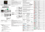
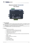
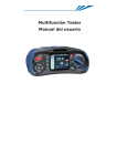
5.2 Defrosting
Two defrosting types are available: electrical (compressor stops) or hot gas (compressor
continues functioning). Other programmable functions are included: defrosting frequency, time
counting type, end defrosting temperature (if the probe 2 is enabled) and max. defrosting time.
When defrosting ends drainage is managed.
5.3 Evaporator fans
During compressor functioning or defrosting cycle it is possible to set fans status by parameter.
Moreover there is the possibility to select temperature above which the fan switches off and the
delay time for start-up after a defrosting.
6. Front panel
Key
Description
Press to visualize setpoint. Press for 3” to enter password (1234) and start
configuration. When entering password next digit flashes. Pressed during
configuration allows to save parameters and esc procedure.
Controls light relay switch-on/switch-off (if enabled by parameter).
During setpoint visualization allows to modify setpoint value. In configuration
DRR132 USER MANUAL
mode scrolls parameters. If pressed with
modifies visualized
parameter.
If pressed for 2” allows to start manual defrosting cycle. During setpoint
visualization allows the modification. During configuration scrolls parameters.
1. General description
DRR132 is a digital controller designed to control cooling/HVAC systems. Available models are
equipped with up to four relays to control compressor, defrosting and fans; the fourth relay can be
configured as light command, auxiliary alarm or like the others. Memory cards are available for
configurations in series.
Referring to the following table it is possible to find required model.
If pressed with
modifies visualized parameter.
Allows to lock/unlock keyboard.
+
Led
2. Ordering codes
Description
Shows compressor status
ON during defrosting
DRR132
X
3
4
X
X
B
T
Shows fan status
1 relay (30A), 1 deviation relay (8A), 1 relay (8A)
1 relay (30A), 1 deviation relay (8A), 2 relays (8A)
230Vac ±10% 50/60Hz
Rs485 with ModbusRTU/slave protocol.
Shows light status
Shows auxiliary out. 1 status
Shows auxiliary out. 2 status
ON when alarm is active
3. Size and installation
ON during Modbus communication
72 mm
64 mm
7. Error messages
DRR132
m
m
0
9
Morsettiere Estraibili
Extractable terminal blocks
Attacco a guida DIN EN50022
Din rail mounting guide EN50022
4. Wiring plan
DRR132 is equipped with screw
terminals suitable for wires of max.
2.5mm2. The NTC/PTC 2 wires have
no polarity. It is a good safety guideline
to separate power line from the probe
wirings.
Cause
Cell probe damaged or
temperature out of limit.
What to do
Verify probe connection and its integrity.
Evaporator probe damaged or
temperature out of limit.
Probe 3 damaged or
temperature out of limit.
Pressure switch alarm.
Verify probe connection and its integrity.
External alarm.
Alarm enabled by digital input.
Door alarm.
Alarm enabled by digital input.
-
Low temperature alarm.
-
Error in EEPROM cell
programming.
Incorrect configuration data:
possible loss of device
calibrations.
Contact technical support
Temperature controlling is always
subject to hysteresis: the compressor
stops when the setpoint is reached and
starts up again when the temperature
exceeds the high setpoint plus the
hysteresis value.
There are also various solutions to
protect the compressor against closer
starts (start delay, minimum off time
and minimum time between the two
successive activations).
If there is a thermostat probe failure,
compressor status will be the one set
on parameter 13
.
Verify that configuration parameters are
correct.
8. Technical data
BOX:
POWER SUPPLY:
CONSUMPTION:
DISPLAY:
ACCURACY:
SAMPLING TIME:
REGULATION:
OUTPUT:
5.1 Compressor
Alarm enabled by digital input.
Switch-off and restart the device.
Hight temperature alarm.
OPERATING CONDITIONS:
INPUT:
5. Operating modes
Verify probe connection and its integrity.
SEALING:
CONFIGURATION:
DIN rail 4 modules
230Vac ±10% 50/60Hz
2.5VA
4 digits 0,4" green
4 digits 0,3" red
8 red LEDs
0…40°C, 0...95rH%
2NTC10K (βvalue3435K) / PTC 1K
1 NTC 10K (βvalue3435K)
0.5%±1digits
20ms
ON/OFF with histeresys
1 relay 30A 277Vac 8310 VA max.
1 relay 8A 230Vac with change-over relay.
2 relays 8A 230Vac
IP65 front panel,IP20 box and terminal blocks.
Parameters protected by password (1234) and memorycard for production in series.
9. Table of configuration parameters
To enter configuration, press
the arrow keys.
REGULATION
N.
Display
1
2
3
4
5
6
for 3'', enter password 1234 with the arrow keys and move the blinking digit with
. To scroll parameters press arrow keys, while to modify them press
Parameter description
(Compressor Hysteresis)
Selects hysteresis into the calculation of intervention thresholds for compressor relay output.
-30.0..30.0°C (°F)
Default: 2.0°C.
(Lower Limit Setpoint)
SET Lower limit. Setpoint cannot be selected under this value.
-40..
(Upper Limit Setpoint)
SET Upper limit. Setpoint cannot be selected over this value.
(Probe 1)
Selects input 1 type.
(Probe 1 Offset)
Offset correction of Cell probe (adds/subtracts degrees to the visualization).
(Probe 2)
Selects input 2 type.
Entering range
°C (°F) Default: -40°C.
..210°C (°F)
Default: 40°C.
(NTC) Cell probe type NTC 10KΩ (β3435K). Default.
(PTC) Cell probe type PTC 1KΩ
-20.0..20.0°C (°F)
Default: 0.0°C.
(Disabled)
(NTC) Evaporator probe type NTC 10KΩ (β3435K). Default.
7
8
9
10
11
(Probe 2 Offset)
Offset correction of Evaporator probe (adds/subtracts degrees to the visualization).
(Probe 3)
Selects input 3 type.
(Probe 3 Offset)
Offset correction of Probe 3 (adds/subtracts degrees to the visualization).
(Output Delay Start-up)
Selects outputs exclusion time after device start up.
(Compressor Sel. Protection)
Selects protection type against close compressor starts.
(PTC) Evaporator probe type PTC 1KΩ
-20.0..20.0°C (°F)
Default: 0.0°C.
(Disabled) Default.
(NTC) Probe 3 type NTC 10KΩ (β3435K).
-20.0..20.0°C (°F)
Default: 0.0°C.
0..120 minutes
Default: 0 minutes.
:(No Protection) No protection.
:(Delay On) Activation delay (default).
:(Delay Off) Min. time for compressor switch-off.
12
13
(Compressor Time Protection)
Selects previous parameter duration.
(Compressor State Error)
Selects compressor status in case of cell probe failure.
:(Delay Between) Min. time between two compressor starts.
0..30 minutes
Default: 0 minutes.
: default.
DISPLAY AND KEYS
N.
Display
Parameter description
(Degree)
14
Selects probe degrees type. When measure unit changes, setpoint and parameters have to be
properly modified.
Entering range
:Converts temperature in Celsius degrees. (Default)
:Converts temperature in Fahrenheit degrees.
15
(Decimal Point)
Selects type of visualized decimal.
:Enteger number (resolution 1°C/F). (Default)
:Decimal (resolution 0,1°C/F).
16
(Visualization Display 1)
Selects display 1 visualization.
:(Probe 1). Default.
:(Probe 2)
:(Probe 3)
:(Setpoint)
17
(Visualization Display 2)
Selects display 2 visualization.
(Disabled)
:(Probe 1)
:(Probe 2)
:(Probe 3)
:(Setpoint). Default.
18
(Setpoint Protection)
Selects type of protection against unintentional modifications of setpoint by the user
:(Free) No protection, user can modify setpoint (Default).
:(Lock) Setpoint cannot be modified by the user.
plus
DEFROSTING
N.
Display
19
Parameter description
Entering range
(Defrost Type)
Selects defrost type.
:(electric). Compressor stopped (default).
:(inversion). Compressor ON (hot gas).
1..50 hours.
Default: 6 hours.
(Defrost Time)
Selects break duration between two defrostings.
(Defrost Count)
Selects break counting type between two defrostings.
20
21
:(Compressor Time On).
Only compressor operating time is counted.
:(Real Time). Break time from defrosting start is the real elapsed time: time
is always the same. (Default).
:(Stop Compressor Defrost).
Defrosting at each compressor stop.
:(Free). Compressor goes on regulating on SET independently from
defrosting.
0..120 minutes
Default: 0 minutes.
-10..60°C (°F)
Default: 10°C.
-10..50°C (°F)
Default: 4°C.
1..120 minutes
Default: 30 minutes.
-40..210°C (°F)
Default: 8°C.
(Defrost Delay)
Delay time for defrosting start.
(Defrost Block Cell)
Selects cell temperature over that defrosting doesn't starts.
(Defrost Block Evaporator)
Selects evaporator temperature over that defrosting doesn't starts.
(Defrost Max Time)
Defrosting duration time.
(Defrost End Temperature)
End defrosting temperature.
(Defrost Start-up)
Allows or not defrosting at device start-up.
22
23
24
25
26
27
: default.
(Defrost visualization)
Selects display visualization during defrosting.
28
:(Real Temperature). Default.
:(Temperature Before Defrost).
:(Setpoint).
(Defrost Visualization Delay)
Selects time to be elapsed from defrosting end before allowing display to visualize real cell
temperature.
(Drainage Time) Selects compressor and fan lock duration after a defrosting.
29
30
FANS
N.
31
Display
32
33
34
Parameter description
(Fan End Temperature)
Temperature above which the fans switch-off (referred to evaporator probe).
(Fan Hysteresis)
Selects histeresys for fans intervention threshold calculation.
(Fan Delay)
Delay time for fans activation after defrosting.
(Fan Disable Defrost)
Locks fans during defrosting.
:(“DEF” label).
0..120 minutes
Default: 0 minutes.
0..120 minutes
Default: 0 minutes.
Entering range
-40..210°C (°F)
Default: 2°C.
0.5..50.0°C (°F)
Default: 2.0°C.
0..120 minutes
Default: 10 minutes.
: default.
35
(Fan Compressor Off)
Selects fans status when compressor is off.
: default.
ALARMS
N.
Display
36
Parameter description
Entering range
(Alarm Type)
:(Deviation Alarm) Alarm intervention thresholds are determinated by the
Selects type of alarm related to parameters
and
.
expression SET+
and SET-
. (Default).
:(Absolute Alarm) ) Alarm intervention thresholds are determinated by
37
(Upper Alarm) Enter the temperature threshold which will activate visual alarm signal if its upper
limit will be exceeded . The threshold depends on parameter
parameters
-40..210°C (°F)
Default: 5°C.
.
38
(Lower Alarm) Enter the temperature threshold which will activate visual alarm signal if its lower
39
limit will be exceeded. The threshold depends on parameter
.
(Alarm Hysteresis) Selects hysteresis into alarm intervention threshold calculation.
-40..210°C (°F)
Default: 5°C.
40
(Temperature Alarm Delay)
Selects alarm activation delay.
0.5..50.0°C (°F)
Default: 2.0°C.
0..120 minutes
Default: 10 minutes.
41
(Alarm Delay Start-up)
Selects alarm exclusion time after device start-up.
(Alarm Delay Defrost)
Selects alarm exclusion time after a defrosting.
0..10 hours.
Default: 2 hours.
0..10 ore.
Default: 1 hours.
42
and
.
DIGITAL INPUT
N.
Display
43
Parameter description
(Digital Input 1Configuration)
Selects digital input operating mode.
Entering range
(Disabled).Default.
(Door).With active input display visualizes
(Door Alarm).
With open port high/low temperature alarms are disabled.
(External Alarm) With active input display visualizes
.
(Pressure Switch Alarm) If during the break time selected on
input detects a number of activation equal to the
value selected on
controller stops compressor and visualizes
active compressor is off.
To restart normal regulation it is necessary to switch-off and restart controller.
(Defrost ) With active input defrosting function starts.
(Pressure Alarm). When input is
(Regulation Type) With active input the device follows an hot type regulation, otherwise regulation is cold.
(2 Thresholds Switch) If active, the controller works according to SET2, otherwise on SET1.
44
(Digital Input 1 Polarity)
Selects type of contact for digital input 1 activation.
:(Open Contact).
:(Closed Contact). Default
45
(Digital Input 1 Output Off)
:(None). Default.
If
=
input activation.
,
: selects outputs to be switched-off during digital
:(Fan).
=
: in case of pressure alarm, selects outputs to be switched-off,
If
excluded the compressor that is stopped.
:(Compressor).
:(Fan and Compressor).
46
(Digital Input 1 Temperature)
If
47
=
: determinates threshold (SET +
) to be surpassed
restart, also with active digital input.
so that option selected on parameter
(Digital Input Time)
0..120 minutes
Default: 0 minutes.
If
=
: Max. deactivation time for outputs selected on parameter
done (Selected options restart with digital input deactivation).
If
48
49
=
: (All).
0.0..50.0°C (°F)
Default: 0.0°C.
Selecting 0 control will not be done (Selected options restart with digital input
deactivation).
with active digital input. Selecting 0 control will not be
: delay between digital input activation and signaling.
If
=
: break time to calculate number of pressure switch activations.
(Digital Input 1 Pressure Switch Number)
If
=
: max. pressure switch activations during
(Digital Input 2 Configuration)
(Disabled).Default.
Selects digital input operating mode.
1..15 activations
Default: 2 activations.
time before alarm signaling.
(Door).With active input display visualizes
(Door Alarm).
With open port low/high temperature alarms are disabled.
(External Alarm) With active input display visualizes
.
(Pressure Switch Alarm) If during break time selected on
the input detects a number of activations equal to
the value selected on
controller stops and visualizes
compressor is off.
To return to the standard regulation it is necessary to restart the device.
(Defrost ) Defrosting function starts with active input.
(Pressure Alarm). When input is active,
(Regulation Type) With active input device realizes an hot type regulation, otherwise the regulation is cold.
(2 Thresholds Switch) If active, the controller works according to SET2, otherwise on SET1.
50
(Digital Input 2 Polarity)
Selects type of contact for digital input activation.
:(Open Contact).
:(Closed Contact). Default
51
(Digital Input 2 Output Off)
:(None). Default.
If
=
input activation.
,
: selects outputs to be switched-off during digital
:(Fan).
If
=
: in case of pressure alarm, selects outputs to be switched-off
excluded the compressor that is stopped.
:(Compressor).
:(Fan and Compressor).
52
(Digital Input 2 Temperature)
If
53
=
: determinates threshold (SET +
so that option selected on parameter
(Digital Input 2 Time)
) to be surpassed
restart, also with active digital input.
0..120 minutes
Default: 0 minutes.
If
=
: Max. deactivation time for outputs selected on parameter
done (Selected options restart with digital input deactivation).
If
54
=
: (All).
0.0..50.0°C (°F)
Default: 0.0°C.
Selecting 0 control will not be done (Selected options restart with digital input
deactivation).
with active digital input. Selecting 0 control will not be
: delay between digital input activation and signaling.
=
: break time to calculate number of pressure switch activations.
If
(Digital Input 2 Pressure Switch Number)
If
=
: max. pressure switch activations during
time before alarm signaling.
1..15 activations.
Default: 2 activations.
LIGHT
N.
Display
55
Parameter description
Entering range
(Light Key)
: (Disabled). Default.
Configuring
or
=
and
or
: (Enabled).
56
USCITE
N.
Display
57
=
or
it is possible to select AUX 1 or AUX 2 as light command.
This parameter allows or not to command light output by keyboard.
(Light Max Time)
Selects max. time for light output activation.
0..120 minutes. If 0 output has to be deactivated manually by keyboard or by digital input.
Default: 0 minutes.
Parameter description
Entering range
(Aux 1 Configuration)
Selects AUX1 ouptut functioning.
:(Disabled). Default.
:(On). Always On with device switched-on.
: (Compressor). On with active compressor.
: (Fan). On with active fans.
: (Defrost). On with active defrosting.
:(Alarm). On with active alarm.
:(Digital Input 1). On with active digital input 1 signaling.
:(Digital Input 2). On with active digital input 2 signaling.
58
(Aux 1 Polarity)
Selects AUX1 output contact type.
:(Normally Open). (Default).
:(Normally Closed).
59
(Aux 1 Disabling)
:(Alarm Off). Output deactivates when alarm conditions disappears
If
=
,
deactivation type (excluded light functioning).
,
: selects AUX1 outuput
(Default).
:(Key). Output deactivates pressing a key.
60
(Aux 2 Configuration)
Selects AUX2 ouptut functioning.
:(Disabled). Default.
:(On). Always On with device switched-on.
: (Compressor). On with active compressor.
: (Fan). On with active fans.
: (Defrost). On with active defrosting.
:(Alarm). On with active alarm.
:(Digital Input 1). On with active digital input 1 signaling.
:(Digital Input 2). On with active digital input 2 signaling.
: (Beeper).
61
(Aux 2 Polarity)
Selects AUX2 output contact type.
:(Normally Open). (Default).
:(Normally Closed).
62
(Aux 2 Disabling)
:(Alarm Off). Output deactivates when alarm conditions disappears.
If
=
,
deactivation (excluded light functioning).
,
: selects output AUX 2
(Default).
:(Key). Output deactivates pressing a key.
63
(Beeper)
:(Key) Beep during key pressure.
If
=
selects beeper operating mode.
:(Alarm) Active in case of alarm.
:(Key and Alarm) Beep during key pressure and active in case of alarm.
(Default)
SERIALE
N.
Display
64
Parameter description
(Baud Rate)
Serial communication Baud Rate.
Entering range
4800 bit/s.
9600 bit/s.
19200 bit/s (Default).
28800 bit/s.
38400 bit/s.
65
66
(Slave Address)
Device serial address.
(Serial delay)
Answer delay for serial communication.
57600 bit/s.
1..254
Default: 254.
0..100 ms
Default: 10 ms.
10. Serial communication
DRR132 is provided with RS485 and can receive/broadcast data via MODBUS-RTU protocol. Device can be configured only as Slave. This function allows to control multiple
controllers connected to a supervisory system. RS485 line has to be free from LT termination resistances to avoid malfunctioning.
Each instrument will answer to a Master query only if contains same address as on parameter
. Allowed addresses are from 1 to 254 and there should not be controllers
with the same address on the same line. Address 255 can be used by the Master to communicate with
all connected equipments (broadcast mode), while with 0 all devices receive command, but no answer is expected. DRR132 can introduce an answer delay (in milliseconds) to
Master request; this delay has to be set on parameter
.
At each parameters modification, instrument stores values in EEPROM memory (100000 writing cycles), while setpoints are stored with a delay of 10 seconds after last modifi
cation.
NB: Modifications made to Words different from those described in the following table can lead to instrument malfunction.
Baudrate
Format
Supported functions
Selectable by parameter
4800bit/s, 9600bit/s, 19200bit/s, 28800bit/s, , 38400bit/s, 57600bit/s
8, N, 1 (8bit, no parity, 1 stop)
WORD READING (max 20 word)
(0x03, 0x04)
SINGLE WORD WRITING
(0x06)
MULTIPLE WORDS WRITING
(0x10)
(max 20 word)
MODBUS ADDRESS
READ/
WRITE
DESCRIPTION
0
1
5
6
50
51
500
1000
1001
1002
1003
1004
1005
1006
1007
1008
2001
2002
2003
….
2069
2070
Device type
Software version
Address Slave
Boot version
Automatic addressing
Installation code comparison
Loading default values:
9999 restore all values
9998 restore all values excluded baud-rate and address slave
9997 restore all values excluded address slave
9996 restore all values excluded baud-rate
Process 1 value
Process 2 value
Process 3 value
Setpoint 1 value
Setpoint 2 value
Relay status (0=off, 1=on):
Bit0: Compressor relay
Bit1: Defrosting relay
Bit2: Light relay
Bit3: Auxiliary relay
Bit4: FAN1 output
Bit5: FAN2 output
Alarm status (0=off, 1=on):
Bit0: High Alarm
Bit1: Low Alarm
Bit2: Digital Input 1 Alarm
Bit3: Digital Input 2 Alarm
Digital input status (0=off, 1=on):
Bit0: Active digital input 1
Bit1: Active digital input 2
Error signalling flags (0=off, 1=on):
Bit0: Errore in eeprom writing
Bit1: Errore in eeprom reading
Bit2: Process error 1
Bit3: Process error 2
Bit4: Process error 3
Bit5: Process error 4
Bit6: Missing calibration error
Parameter 1
Parameter 2
Parameter 3
….
Parameter 69
Parameter 70
RESET VALUE
RO
RO
RO
RO
WO
WO
R/W
104
FLASH
EEPR
FLASH
0
RO
RO
RO
R/W
R/W
RO
0
0
0
EEPR
EEPR
0
RO
0
RO
0
RO
0
R/W
R/W
R/W
R/W
R/W
R/W
EEPR
EEPR
EEPR
EEPR
EEPR
EEPR
PIXSYS
www.pixsys.net
e-mail: [email protected] - [email protected]
2300.10.170-RevA 040609
*2300.10.170-A*