1
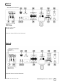
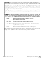
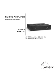
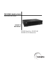
I n s ta l l a t i o n
Front Panel Controls and Displays
F R O N T P A N E L C O N T R O L S A N D D I S P L AY S
Figure 1: Front Panel Connections of the SC-600 amplifier.
Following are brief descriptions of the controls described in Figure 1. More detail on these
controls can be found in the next section.
(1) Power Switch
This button forces your SC-600 amplifier into standby mode. The power LED turns amber,
the numeric LED shuts off, and the amplifier puts out no power. The unit will remain in this
mode until the POWER button is pressed again. To fully deactivate (i.e. power down) the unit,
use the main power switch on the back panel.
(2) Power LED
This LED illuminates when the power is on. Blue is normal operation. It turns amber when
the unit is in standby mode or the remote has been used to deactivate the unit, and dims
when the unit is in night mode.
(3) Mic Input
Connect the supplied microphone for the Auto-EQ feature to this mini-jack input.
(4) Remote Eye
This is the eye that receives infrared commands from the supplied remote.
(5) Low-Pass Crossover
Use these up and down buttons to select the high-frequency range at which you wish to cut
off the signal to the subwoofer. The frequency is indicated on the LED display briefly, then
the display reverts to showing the subwoofer’s volume level. The slope is fixed at 24
dB/octave. To deactivate the crossover, press BOTH the up and down crossover buttons at
the same time – two dashes on the display indicate the crossover is deactivated and the
woofer plays all frequencies presented to it. Please see page 8 for a more detailed
discussion on crossovers.
.
www.velodyne.com
SC-600 Amplifier User’s Manual
3