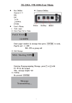
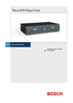
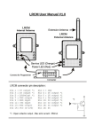
1
WaveWare Paging Data Receiver WaveWare RCD-1 Remote Control and Data Module W av eWare T ech n o lo g ies In c. User Manual October 2004 WaveWare Technologies, Inc. 9726 Skillman St. Dallas, Texas 75243 Ph: 972-479-1702 Fax: 972-479-1735 Email: [email protected] WaveWare Paging Data Receiver RCD-1 User Manual This manual covers the following products: Part Number: 0604-1001 RCD-1 Remote Control and Data Module. Available in VHF POCSAG, UHF POCSAG, and 900 band FLEX. Specify operating frequency, capcode, and RF data rate (VHF/UHF only). Also specify interface type: LED sign, PC data, Remote Switching, or LED sign with Annunciation. Copyright 2004 by WaveWare Technologies, Inc. This manual is Copyrighted and may be reproduced for distribution with the RCD-1 series of products as long as the manual remains intact, in its entirety, with all Copyright, intellectual property, and Trademark notices. Portions of this manual are copyrights of Gold Apollo Co., Ltd. Notice: Changes or modifications to this device that are not expressly approved by WaveWare are prohibited and could void the user’s warranty and possibly his authority to operate this product. 2 WaveWare 1. Paging Data Receiver Table of Contents 1. Table of Contents.................................................................................................................................... 3 2. Specifications.......................................................................................................................................... 4 3. Introduction............................................................................................................................................. 5 4. Addressing .............................................................................................................................................. 6 5. Serial Data Output................................................................................................................................... 7 6. Control Output ........................................................................................................................................ 8 7. Annunciation......................................................................................................................................... 10 7.1. Command Messages (Selective Annunciation) .............. 10 7.2. Internal Function Commands (Global Annunciation) .... 11 8. Programming......................................................................................................................................... 12 9. 8.1. Programming Screens .................................................... 12 RCD-1 Connectors ............................................................................................................................... 14 9.1. External Antenna Jack.................................................... 14 9.2. Power/Data Modular Connector..................................... 14 9.3. Relay Output Connector................................................. 14 9.4. Power/Data LED ............................................................ 14 10. Warranty ........................................................................................................................................... 15 10.1. Limitations of Warranty: ................................................ 15 10.2. Warranty Procedure ....................................................... 15 3 WaveWare 2. Paging Data Receiver Specifications Physical and Environmental Specifications Dimensions: Operating Temperature: Humidity: Vibration: Shock: RF I/O: 3.70” x 5.75” x 1.33” enclosure, not including connectors or antenna -10 to +60°C 95 % non-condensing 0.27 G (5 to 500 Hz) 3G or 2 ft. drop external rubber duck antenna General Electrical Specifications Power supply: Frequency stability: Power consumption: Frequency range: RF circuits no-tune bandwidth: Received Signaling Format and speed: Maximum message length: +5VDC 3ppm <80mA at 5V 150-160MHz (POCSAG) 450-470MHz (POCSAG) 929-931MHz (FLEX) 10MHz VHF, 462-470MHz UHF, 4MHz FLEX (using external antenna) POCSAG at 512, 1200, or 2400 bps (VHF/UHF only), or FLEX (900 band only). 2000 characters Specifications of Receiver Section Receiver sensitivity (512 bps): 99% decode at 0.20uV measured at SMA connector. Adjacent channel rejection: Image and spurious rejection: Intermodulation rejection: Channel Spacing: 65dB 55dB 60dB 25 kHz User Features Digital outputs: Serial output: Address codes: Serial port baud rates: Control outputs: 1 Relay output, SPST-NO, Form A, 2A 30VAC or 30VDC rated capacity, 10mA minimum current load 2-wire RS-232 (TX and GND) 8 capcodes with 4 function codes per capcode (POCSAG), or 16 capcodes (FLEX) 2400, 4800, 9600, 19200, 38400 The relay output responds to commands similar to Motorola’s DataNet RCD1, e.g. 77XX and 7014X formats. The relay output can also be configured to automatically activate for X seconds on new message arrival. 4 WaveWare 3. Paging Data Receiver Introduction The RCD-1 family of paging data receivers are high performance receiver modules which are ideal for remote control, one-way telemetry, and wide-area wireless messaging. They feature: • • • • • • • • • • • • • • 1 relay output port, configurable as automatically or command code controlled Uses POCSAG or FLEX digital paging formats, depending upon factory configuration Receives 512, 1200, or 2400 baud POCSAG (applies only to POCSAG Model) Synthesized receiver - No crystals required RS-232 port for data output Compact size Activity and Power LED Receives alpha or numeric messages External antenna Timed or static digital output when relay output is used Positive lock connectors Wall mountable case Directly compatible with Adaptive™ LED message boards Responds to industry standard “7xxx” output control commands when configured for relay control mode WaveWare’s RCD-1 paging data receivers allow a user to remotely control electrical devices over very wide areas, even nation-wide! Because they use industry standard paging protocols, an RCD-1 communication system may be as small or as large as one wishes. A user may utilize their own on-site transmitter or they may utilize a paging carrier’s wide-area network. The RCD-1 receivers decode paging signals, and provide an RS-232 output of the received message. If the RCD-1 is configured for remote control, and a message is formatted in the common “7xxx” output control format, the digital output relay will respond appropriately. The digital output may be used to control relays, external loads, or a host of other electro-mechanical devices. A built-in timer allows the outputs to be turned on for specific amounts of time, after which they are automatically turned off. This is particularly useful for lighting and pump control. 5 WaveWare 4. Paging Data Receiver Addressing The POCSAG communication protocol is used to send data to VHF and UHF versions of the RCD-1. POCSAG requires that all data transmitted be sent to a particular address. POCSAG addresses use a 21 bit address, meaning they are in the range of 0000001 through 2097151. Some companies refer to these addresses as capcodes. The 900 band version of the RCD-1 receiver uses the FLEX communication protocol. Up to eight addresses (capcodes) can be programmed into an RCD-1 receiver POCSAG models, and 16 addresses can be programmed into the RCD-1 receiver FLEX models. One capcode is generally used for the unit’s individual address, and another is generally used as a group address. The POCSAG models of the RCD-1 receiver can also be configured to use POCSAG function codes for addressing. There are four POCSAG function codes per capcode. “7xxx” output control commands and data messages can also include an additional sub-address or password that can be used to share one capcode between a number of devices. The RCD-1 will respond to up to two passwords or sub-addresses, allowing one to be used as an individual address and the other to be used as a group address. It is possible to selectively control serial data output using sub-addresses. The addresses are programmed into a unit via PC programming software and a programming kit. Refer to the Programming Section of this manual for information on how to program the RCD-1. 6 WaveWare 5. Paging Data Receiver Serial Data Output The RCD-1 provides an RS-232 type serial output interface. When configured for serial data output, all messages that are received by the RCD-1 are sent out the RS-232 serial data interface in the ASCII format. For a message to be properly received, it must be sent to an address that matches one of the addresses programmed into the RCD-1. Output control commands can be associated with addresses, allowing automatic output control upon reception of a new message for a particular address. See the Annunciation Section of this manual for details. Some paging carriers insert dashes into messages sent to numeric pagers. If this is a problem, contact your carrier and request that dashes not be inserted, or tell them to send the messages in alphanumeric format. The RCD-1 RS-232 port is a 3-wire interface, and thus does not use hardware flow control. The serial port output baud and parity are programmable using the optional programming kit. An up to 30 character message Header and Trailer may be programmed into the RCD-1, entered as HEX values, for each address. If a pre-programmed header and/or trailer are configured, these will be concatenated with every data message the RCD-1 sends to the serial port. If the pre-programmed header is configured, the character(s) configured will always be transmitted out the serial port immediately before the received message. If the pre-programmed trailer is configured, the character(s) will be sent out immediately after the received message. In addition to headers and footers, there is a Timeout field associated with each address. If the Timeout field is configured for a given address, and the Msg Time Out Delay value is greater than 0 seconds, the Timeout field value will be output on the RCD-1 serial port when the Msg Time Out Delay time is elapsed after a new message is received for that address. The Msg Time Out Delay time value can range from 0 to 65,000 seconds (approximately 18 hours). The Carriage Return insertion or Line Feed insertion feature may be enabled or disabled during programming to allow the serial output to work properly with a variety of printers. The Insert CR After Detected LF option will cause a Carriage Return to be inserted before any detected Line Feed character in the message. Similarly, the Insert LF After Detected CR option will cause a Line Feed to be inserted after any Carriage Return in the message. If the data rate of the RS-232 serial port is slower than the rate at which messages are sent to the RCD-1 it will buffer the messages as it receives them. The buffer in the RCD-1 is 2,000 characters deep. If the buffer fills, the next message received will overwrite the buffer. If the baud rate of the serial port is equal to or greater than the over-the-air POCSAG rate, the buffer will never overflow, and the message length is limited only by the accuracy of the transmit and receive baud rates. Message lengths of 512 characters or less are recommended. 7 WaveWare 6. Paging Data Receiver Control Output The RCD-1 has 1 relay output. The output is a Form A, 2A rated contact, SPST-NO, with a 10mA minimum current load and a 2A maximum current load, and a 30VDC and 30VAC maximum voltage rating. When configured for relay command control mode, certain commands are used to set and clear the relay. The commands must be a series of numeric digits sent to one of the RCD-1’s addresses. The RCD-1 responds to commands in a manner very similar to Motorola’s DataNet paging receivers. When configured for serial data output, a particular address can be configured to perform a relay control function as each message is received. Upon power up, RCD-1 can set the relay output to whatever state was stored in the EEPROM prior to the last power down or to a state configured in the programming software. RCD-1 Output Control Commands are in the following format: Function Code + Command Code + Sub-Address + Data + Checksum The Sub-Address and Checksum are optional. If sub-addressing is enabled in the RCD-1 receiver, then the Sub-Address field is required. If checksum processing is enabled in the RCD-1 receiver, then the Checksum field is required. The Function Code determines what function is going to be performed, or which control output is going to be acted upon. The Command Code tells the logical polarity of the output, or what to do with the output referenced in the Command Code. The sub-address field can be used to specify an individual RCD-1 receiver within a group of receivers configured to share a common CAP Code, or as a password used to validate output commands. Two passwords of up to 10 characters in length can be configured in the RCD-1 receiver. When used as subaddresses, one can be used as an individual address and the other as a group address. The Data field is used to control the relay output. The number in the data field is the polarity to set the relay to. The number in the field must be either a “0”, or a “1”. A “0” will deactivate the relay, and a “1” will activate the relay. The Checksum is a bit-for-bit EXCLUSIVE OR function across every ASCII byte in the command. The result of the XOR is converted to a two-byte HEX ASCII code. See the example for details. If you do not wish to use a checksum at the end of the message, you can disable it with the programming software. Function Code Command Code Description 70 00 14 No output change Configure state of the relay. Output Relay Deactivate relay Activate relay Cycle (activate, delay, deactivate) Cycle (deactivate, delay, activate) 77 10 11 12 13 Command Examples: To send a command to activate the relay, the following command could be sent: 7711 An alternative way to activate the relay is: 70141 8 WaveWare Paging Data Receiver To send a command to activate the relay for one minute, and then have it deactivate automatically, send the following command. Note: The RCD-1 unit must have its timer already programmed to be one minute, using the Output 1 Period field in the programming software. The RCD-1 can be programmed to have a delay value as long as approximately one hour and 45 minutes, or as short as one second. See the Programming Section of this manual for details. 7712 Checksum Example: Message: 7014123450 Function code = 70 Command code = 14 Password = 12345 Data = 0 (turn output relay OFF) Checksum: 37h XOR 30h XOR 31h XOR 34h XOR 31h XOR 32h XOR 33h XOR 34h XOR 35h XOR 30h = 03h Converting the answer, 03h, to HEX ASCII yields two characters, one for the 0 and one for the 3. Therefore, the actual message to send to the RCD-1 is : 701412345003 Note: ASCII-HEX representation of Checksums can result in non-numeric characters so alphanumeric POCSAG formatting should be used when command checksums are present. Also, command passwords/sub-addresses can also contain non-numeric characters. 9 WaveWare 7. Paging Data Receiver Annunciation There are two methods of annunciating message arrival for applications that need to perform digital output manipulation while outputting message text to the serial port. The first method, called “Selective Annunciation”, is to send a 7xxx command prefix along with the message text. The second method, called “Global Annunciation”, is to configure 7xxx commands to be executed immediately when the unit’s CAP Code is recognized, for all received messages. NOTE: It is not recommended that either method be used to “power up” external equipment that will be receiving the message text through the serial port. This is because the timing between Output Control Command execution and message text output is not deterministic and may result in messages being output before the receiving equipment it prepared to process it. 7.1. Command Messages (Selective Annunciation) Under normal circumstances output commands and text messages are sent as separate POCSAG messages. When the Function Command mode is enabled, text messages must be prefixed with a valid 7xxx output command, including passwords and/or checksums when configured. Messages not containing a valid 7xxx prefix are discarded and not output on the serial port. When a valid 7xxx command is included, the command is executed (and output on the serial port when serial output is enabled and Function Command Output Filtering is disabled) then the text following the command is output along with the configured header and trailer strings. This feature provides security and/or sub-addressing functionality for text messages as well as annunciation functionality on a message by message basis. When no output change is desired, the 7000 command should be used. This command allows password/subaddress and checksum processing without performing any output activities. Selective Annunciation Mode Examples: Received message: “Open 9-5 Mon-Fri” Relay response: none Serial output: none Notes: 7XXX command prefix not included in message Configuration: Subcode 1=123, Subcode 2 = 999 Received message: “7000Hello” Relay response: none Serial output: none Notes: Subcode not included as part of message prefix Configuration: Subcode 1=123, Subcode 2=999, Header=3C, Trailer=3E Received message: “7000123What’s up?” Relay response: none Serial output: “<What’s up?>” Notes: Includes proper 7XXX command and Subcode value. Header hex value of 3C = ASCII < character Configuration: Subcode 1=123, Subcode 2=999, Header=3C, Trailer=3E Received message: “7000WowAre you ready?” Relay response: none Serial output: none Notes: Password value of “Wow” doesn’t match programmed values of “123” or “999” Configuration: Output Period = 10 sec., Header = blank, Trailer = blank Received message: “7712999Hello World” Relay response: Relay enabled, delay for 10 seconds, then disabled. Serial output: “Hello World” 10 WaveWare Paging Data Receiver Configuration: Subcode 1 = 123 Received message: “70141231Hello World” Relay response: Relay enabled Serial output: “Hello World” 7.2. Internal Function Commands (Global Annunciation) The Internal Function Command field, associated with each address, is used to enter 7xxx output control commands to be executed upon recognition of the RCD-1’s capcode (address). When configured, the command corresponding to the capcode (FLEX model) or capcode/function bits (POCSAG model) is executed as soon as the Capcode match is recognized. Any text following any output control code in the received message will be output through the serial port. In the POCSAG model of the RCD-1, there are four function code command entries corresponding to the four possible POCSAG function bit combinations. If an entry is left blank, or disabled, no relay control command will be executed upon reception of that function code. When only one response is desired, regardless of function code, all four function code entries per capcode should be set to contain the same 7XXX command value. This feature provides the ability to automatically annunciate the output of all message text on the serial port using the relay output. The common application of this feature is to cause a horn and/or strobe to sound each time a new message is displayed on an LED message board. 11 WaveWare 8. Paging Data Receiver Programming The RCD-1 is configured by connecting a computer’s RS-232 serial port to the programming port on the receiver module within the RCD-1, using a programming kit that includes an interface board, connecting cables, power supply, and programming software. The programming kit is sold as an optional item. The RCD-1 incorporates a Gold Apollo receiver module, and uses the Gold Apollo programming hardware and software to configure the RCD-1 feature set. 8.1. Programming Screens Following are snapshots of the two screens in the RCD-1 programming software: 12 WaveWare Paging Data Receiver 13 WaveWare 9. Paging Data Receiver RCD-1 Connectors Fig. 2 - RCD-1 Side View The RCD-1 Enclosure has the following features: 9.1. External Antenna Jack An SMA female connector is located on the top of the RCD-1. It allows one to connect an external antenna to the RCD-1. WaveWare includes an external antenna as standard equipment on the RCD-1. 9.2. Power/Data Modular Connector An RJ-12 6 pin modular positive lock connector is provided for both power and data connections to the RCD-1. The power/data modular connector has the following functions: Pin Function 1 +5V Input 2 N/C 3 TXD 4 N/C 5 N/C 6 GND The modular connector allows direct connection to an Adaptive™ LED message board using a straight wired 6 pin modular patch cable. When using the RCD-1 to deliver RS-232 data to a PC, an optional DB9F modular adapter is available, that combines power and data into the adapter. When using the RCD-1 only for remote circuit switching, a power adaptor is direct connected to the power/data modular connector, and a relay output interface harness is connected to the relay output connector (see below). 9.3. Relay Output Connector The relay output connector is a two pin Molex connector providing a positive lock connection between the RCD-1’s onboard relay and external annunciation devices. An optional relay output interface harness is available for connecting the external annunciation devices with the RCD-1 (see Fig. 2 above). 9.4. Power/Data LED The power/data LED indicates both power and when data is received. On powerup, the power/data LED is always illuminated. When data is output on the serial port, the power/data LED will momentarily blink. 14 WaveWare 10. Paging Data Receiver Warranty WaveWare Technologies, Inc. Limited Warranty Subject to the Limitations of Warranty and the Warranty Procedures, hereinafter set forth, WaveWare Technologies Inc. (WaveWare) hereby warrants this product to perform substantially in accordance with its specifications for a period of one year from the date of original purchase from WaveWare. WaveWare’s sole obligation under this warranty and the purchaser’s exclusive remedy under this or any other warranty expressed or implied, is the adjustment, repair, or replacement, at Sonik’s discretion, of the defective WaveWare product. Some states and jurisdictions do not allow limitations of an implied warranty, so the above limitation may not apply to you. This warranty gives you specific legal rights, and you may have others, which vary from state/jurisdiction to state/jurisdiction. WaveWare assumes no liability for consequential damages whatsoever. 10.1. Limitations of Warranty: a. This warranty is extended only to the original purchaser of the product and shall not be valid or enforceable unless such original purchaser shall have proof of purchase. This warranty does not apply to products sold under OEM agreements, and/or private label arrangements. b. This warranty is limited to repair or replacement of any materials found to be defective, any required servicing or adjustment of the product, or replacement of any materials found to be defective, or replacement of the product if WaveWare deems the repair of the product as ineffective or uneconomical. c. Tampering, misuse, attempted repair, or damage to this product shall invalidate this warranty. d. This warranty only applies to this product as it existed at the time of original purchase by the original purchaser from WaveWare. WaveWare may make design modifications and improvements to this product and shall be under no obligation to modify or alter this product to conform to such changes, additions, software bug fixes, or improvements. e. WaveWare assumes no responsibility for any consequential damages caused by or arising out of any such defect in materials or workmanship, or with respect to any breach of any implied warranty applicable to this product. f. WaveWare assumes no liability for consequential damages whatsoever. To the maximum extent permitted by law, in no event shall WaveWare or its suppliers be liable for any special, incidental, indirect, or consequential damages whatsoever (including, but not limited to, damages for loss of business profits, business interruption, loss of business information, or any other pecuniary loss) arising out of the use, or inability to use, the product, even if WaveWare has been advised of the possibility of such damages. WaveWare and its suppliers disclaim all other warranties, either expressed or implied, including but not limited to, implied warranties of merchantability or fitness for a particular purpose with regard to this product, its hardware, its software, or its firmware. Because some states do not allow exclusion of limitation of liability for consequential or incidental damages, the above limitations may not apply to you. 10.2. Warranty Procedure To obtain warranty benefits provided by this warranty, it is the responsibility of the original purchaser to conform to the following procedures: a. Call WaveWare Customer Service Department and receive a Return Material Authorization Number (RMA). b. Without expense to WaveWare, return this product to WaveWare, attention of the Customer Service Department. WaveWare recommends that you insure the shipment for full value as WaveWare is not responsible for lost 15 WaveWare Paging Data Receiver shipments. Mark the outside of the shipping carton with the RMA number. Inside the shipping carton include the following items: • • • • The product, properly packaged. A full description of the defect for which warranty remedy is sought. Return address. Contact name and telephone number of person familiar with the problem/defect. 16