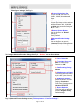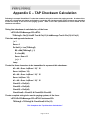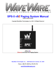
1
W I R E L E S S C O M M U N I C A T I O N S Y S T E M S Paging System Manual Version 8.XX Firmware WaveWare Technologies, Inc. 2012 - All Rights Reserved WaveWare SPS-5 v8 Paging System WaveWare Technologies, Inc. 2630 Garland, TX. 75041 Phone: 1.800.373.1466 Fax: 972.479.1735 www.WirelessMessaging.com Page 1 of 59 Table of Contents Introduction Warranty and other Misc Information Obtaining Pagers for your Paging System Paging System Operation Paging System Installation Quick Start Guide Programming Guide Appendix “A” – TAP Interface Specifications o System ID Command o o o Paging Session “Log-Out” Appendix “B” – Com Port Settings Appendix “C” – TAP Checksum Calculations Appendix “D” – TAP Response Codes Appendix “E” – Extended ID Processing Appendix “F” – Embedded Control Characters Appendix “G” – WaveWare Interface Specifications o Paging Message Command o Response to all Commands o Setup Command o Status Command Appendix “H” – COMP1 Interface Specifications Appendix “I” – COMP2 Interface Specifications Appendix “J” – Scope Interface Specifications o Paging Message Command o Response to all Commands o Setup Command o Status Command Appendix “K” – Timed Message Function Appendix “L” – Connectors and Indicators Appendix “M” – Site Survey Trouble Shooting Page 2 of 59 Page Page Page Page Page Page Page Page 3 7 8 9 10 11 12 26 Page Page Page Page Page Page 30 32 33 34 36 37 Page Page Page 45 46 48 Page Page Page Page 56 57 58 59 Introduction Your WaveWare v8 Paging System allows you to send paging messages to one or more persons via pagers, and devices that incorporate POCSAG paging data receivers. You can setup automatic transmission of messages or you can compose messages on the fly and transmit them immediately. The WaveWare Paging Encoder can be provided in either standalone form or bundled with a radio transceiver to become a paging system. When you attach your paging system to a PC or other Host Device, plug in the provided power adapter, and install and activate your paging software, you will be ready to make full use of the paging system. The WaveWare v8 Paging System can have a pager database programmed using the WaveWare Paging Encoder Setup Software, or you can immediately use the WaveWare v8 Paging System without programming. Your WaveWare Paging Encoder, using v8.XX firmware, has the following capabilities: Serial Port Controlled Operation via RS-232 Serial Port with “Programmable” Communication Parameters. Baud rates of 300, 1200, 2400, and 9600, with None, Even, and Odd parities. Default setting is 9600 N81, unless specified differently by Customer Requirements. Single or Dual RS-232 Serial Com Ports (Dual is Optional) 2 or 5 watts, 2 watts effective radiated power with approximately 1 mile range, depending upon terrain and obstructions. 5 watt Model also available. UHF Band (450-470MHz) Synthesized Transceiver. See the Label on the back of the SPS-5 v8 Paging System to Identify the Operating Frequency of the Paging System. (Optional VHF Band) Industry Standard POCSAG Paging Protocol Covering the Full Range of Paging Functions, Including: 512, 1200 and 2400 bps RF data rates, auto-switching Alphanumeric (Text), Numeric and Tone/Vibe Only Paging Message Formats Multiple Tone and Vibration Patterns Batch Message Delivery, with up to 240 Characters per Message (500 Characters in WaveWare Mode) Support for Multiple Paging Control Protocols, Including: TAP v1.8 (Variations also known as IXO and PET) Extended TAP (TAP Compatible Extended Interface Supporting Embedded Control Characters and Paging Message Encoding Parameters Appended to the Pager ID) Simplex TAP, a Single Serial Command String Composed of a Standard TAP Message Block. NOTE: Simplex TAP is the Recommended Interface Protocol for System Developers. COMP1, Delivery of <CR> or <CR><LF> Delimited Data to One or More Pagers COMP2, a Command String Composed of PagerID<CR>Message<CR> SCOPE, a Proprietary Single Serial Command String that Includes Cap Code, Function Code, RF Data Rate, and Message Values. Scope Protocol can be used as Either Simplex or Duplex Operation. WaveWare, a Proprietary Single Serial Command String that Includes Cap Code, Function Code, RF Data Rate, and Message Values. WaveWare Protocol can be used as Either Simplex or Duplex Operation. Programmable Carrier Signal Detection, Which allows the Automatic Delay of Transmission while a nearby Transmitter of the same Frequency is Operating. Box, Checked (“ON”) Box, Un-Checked (“Off”) Default is Box, Checked (“On”) Page 3 of 59 Programmable On-board Pager Database, Supporting 5,000+ pagers, and up to 10 Groups of 20 Pager IDs each, Stored in Non-Volatile EEPROM Memory. The Pager Database is “Not Required” for WaveWare Protocol, Scope Protocol, Extended TAP Protocol, or Pager ID as Cap Code Mode. Windows 32 bit Software, called “WaveWare Paging Encoder Setup” is provided for Pager Database Programming, Com Port Settings, Range Testing, and General Messaging. Programmable On-board Watchdog Timer, To Keep the Paging System On-Line at All Times. Programmable Verbose or Non-Verbose Modes, Default is Verbose TAP. Verbose Output Means the Paging System Responses Include more Information than Non-Verbose Responses. Programmable Transmitter Duty Cycle Management, In Percentage, from 0 to 100. Default is 50% Duty Cycle. A 0 value also means 100%. Remote Administration of Pager Database, Pager Database can be “Modified” using Specially Formatted TAP Paging Messages. Programmable Timed Messaging Function, Allowing the Paging System to Monitor the Host System, and Automatically Deliver Alert Paging Messages if the Host System does not communicate to the Paging System within a Two Minute Time Cycle. The Timer Triggered Messaging Function can be Enabled or Disabled via Programming, and can be used as a Repetitive RF ping for Fully Supervised Applications. Predefined Alert Messages can be up to 60 Characters in Length. Programmable Maximum Batch, Size for Batch Messaging, Ranging from 1 to 32 Messages per Batch. Batch Messaging allows Higher Message Throughput by Outputting a Single POCSAG Preamble for the Batch of Messages. Default Max Batch is “10” Programmable Pager ID as Capcode mode, This Mode allows a Pager ID value in the COMP2 or TAP Protocols to be treated as a Cap Code, allowing a Bypass of the Pager Database, and allowing Direct Encoding of the Pager ID value as the Pager Cap Code. This Method Reduces Database Configuration Efforts and Opens the Paging Encoder up to use of the Full Approximately 2 Million POCSAG Cap Code Values. Programmable Carrier Detect Polarity, Supports Integration of the WaveWare Paging Encoder to a Variety of Radio Transmitters. Choice of 0v or 5v Default is “0v” Programmable Data Encoding Polarity, Supports on the Encoding of Messages: Normal Polarity Inverted Polarity Default is “Normal” Programmable Flow Control Signaling, Choose either: None Hardware Software Alt Hardware (Flow before ACK/NAK) * Alt Software (Flow before ACK/NAK) ** Default is “Hardware” (RTS/CTS) Additional Information: * Alt Hardware (Flow before ACK/NAK): ** Alt Software (Flow before ACK/NAK): Page 4 of 59 The WaveWare v8 paging encoder is used in the following product models: SPS-5 v8 Paging System: Single Serial Com Port and 2 or 5 watt output. Encoder Only for OEM applications: Single Serial Com Port and adjustable radio Interface. The WaveWare v8 paging encoder can operate simultaneously on two types of alert event activity, including: Serial Port Paging Commands received on the Single or Dual (Optional) Serial Com Port Timer Triggered Delivery of paging messages (Also called Timed Messaging) The WaveWare v8 Paging Encoder can simultaneously receive data on the input serial port while encoding paging messages and delivering the paging messages through the attached radio transmitter. The WaveWare v8 Paging Encoder can output messages up to 500 characters in length in WaveWare mode, or up to 240 characters in other serial port modes of operation. The WaveWare v8 Paging Encoder can operate without a pager database, if you use one of the direct encoder control methods available. If you use traditional paging system control systems that use Pager ID values that are expected to be translated into pager capcodes, then you should use the pager database configuration functions. Direct Encoder Control is available in the following ways (allowing a pager database to not need to be programmed into the encoder): Setting “Pager ID as Capcode” Mode On, and running TAP or COMP2 Input Mode Using Extended Pager ID Encoding method and running TAP Input Mode or COMP2 Input Mode Using Scope Input Mode Using WaveWare Input Mode The WaveWare v8 Paging Encoder’s pager database is organized into four sections: Pager Families Pager Groups Canned (Predefined) Messages Settings Pager Families “Pager Families” are sequentially defined ranges of pager IDs, where the pagers in each range have common attributes, such as pager type, function code, data rate, etc. Capacity of the “Pager Families” database is 50 “Pager Families” of up to 999 pagers per family, for well over 5,000+ pagers. Pager Groups “Pager Groups” are randomly defined lists of up to 20 pager IDs per group, where a Group ID triggers output to the list of pagers in the group. The capacity of the “Pager Groups” database is 10 pager groups of up to 20 pagers per group. Predefined Messages “Predefined Messages” are stored messages used for the following types of functions: Paging message Prefix Paging message Suffix Timer Event Triggered paging message “Predefined Messages” can be up to 60 characters in length and the v8 encoder can support up to 15 “Predefined Messages”. Page 5 of 59 Settings The v8 “Settings” is Split into two Areas: “Encoder Settings” and “Advanced Encoder Settings”. The “v8 Encoder Settings” allows Setup of the Following: The “Protocol” of each RS-232 Serial Com Port (Single and Dual) - TAP, WaveWare etc. The “Settings” of each RS-232 Serial Com Port (Both Ports) - Verbose or Non Verbose and 9600 N 8 1, etc. The “Advanced Settings” Button, allows changes to Advanced Options. The available “Advanced v8 Encoder Settings” options include: Transmitter Duty Cycle %: 0% to 100% Max Messages per Batch: 10 or 32 Carrier Signal Detection: “On” or “Off” Carrier Detect Polarity: 0v or 5v Serial Port Reset of Timed Paging: “On” or “Off” Assume Pager ID is Capcode: “On” or “Off” Data Encoding Polarity: Normal or Inverted Flow Control: None, Hardware or Software Restore Defaults Button: Resets both Com Ports to Factory Defaults Transmitter Duty Cycle: Transmitter Duty Cycle % values can range from 0 to 100. 0 and 100 values cause the duty cycle management function of the encoder to be disabled. Any value from 1 to 99 causes duty cycle management function to be enabled. The lower the number, the greater the delays between transmissions caused by the encoder, to accommodate the duty cycle requirements of specific radio models attached to the WaveWare paging encoder. If there are concerns about the duty cycle requirements of a particular radio, duty cycle values of 33, 50, or 66 are reasonable numbers to consider using. Max Messages per Batch: The Max Messages per Batch value can range from 1 to 32. The WaveWare paging encoder supports batch paging, where multiple messages can be included in a single key up cycle on a radio. Batch paging allows more efficient use of the radio and delivers messages quicker, because one preamble sequence is delivered at each “Key-up” of the radio and multiple pager IDs and messages may be interspersed in a single transmission cycle. Optimum message batching occurs when all pagers operate with the same data rate, such as 512 bps (bits per second). The WaveWare Paging Encoder is able to auto-switch between data rates, which breaks up a batch into smaller batches. Carrier Signal Detection: The WaveWare paging encoder supports the monitoring of carrier signal detection signals from radio receivers. If a receiver reports a detected carrier, the encoder will halt transmission output until the carrier signal is no longer detected. Serial Port Reset of Timed Paging: If Serial Port Timer Reset mode is enabled, the encoder will reset the internal two minute timer each time a paging message or ATI command is received on the input serial port. If no paging messages or ATI commands are received on the input serial port within two minutes, a timer triggered event will occur, with any active Timer functions in the Pager Groups database being processed. If Serial Port Timer Reset mode is OFF, timer triggered messaging will occur regardless of input serial port activity. Pager ID as Capcode – If “Assume Pager ID is Capcode” mode is enabled, all incoming pager IDs on the serial port are treated as capcodes, and must meet the capcode formatting requirements of 1 to 7 digits in length, ranging from 9 to 2097143. Leading zeroes are optional. In addition, no pager ID lookup occurs in the pager databases while this mode is enabled. You can demonstrate this by enabling this mode, then using the Lookup ID function button in this software. Carrier Detect Polarity – The WaveWare v8 Paging Encoder is compatible with radios and radio receivers that output TTL level voltage shifts as a carrier signal is detected. Some radio receivers output 5V upon carrier detection, while others drop to 0V. 0V is the default for the WaveWare SPS-5 v8 paging system, when Midland SD-226 radios are used with the unit. Data Encoding Polarity – The POCSAG radio paging specification allows the encoded paging message to be encoded with one of two polarities. Many pager models are programmable to have normal or inverted data decoding. This is a global setting, meaning all pagers used with a particular encoder installation must match the specified method of data encoding. Page 6 of 59 Warranty and Other Information Warranty: WaveWare Technologies, Inc. warrants this equipment to operate properly for a period of one year from date of shipment from WaveWare Technologies, Inc. Warranty includes parts and WaveWare factory labor, but does not include shipping charges. The warranty becomes void if the equipment is physically damaged by any external events. Disclaimer: This equipment has not been designed to operate as a primary means of life/safety communications, and should only be used as a secondary means of communications. The nature of radio paging is such that alert messages are not guaranteed to be delivered to pagers, due to a variety of causes, some of which are out of the control of the equipment manufacturer and the user of the equipment. The WaveWare paging equipment uses a one-way radio paging protocol called POCSAG, which relies upon proper operating frequency coordination and licensing, proper external environmental conditions, and proper equipment maintenance, in order to deliver messages to pagers in a reasonably reliable manner. WaveWare Technologies, Inc. is not liable for damages caused by failure of delivery of messages from WaveWare equipment to pagers, beyond the normal warranted equipment repair or replacement during the warranty period. Note: This equipment has been tested and found to comply with the limits for a “Class A” digital device, pursuant to part 15 of the FCC Rules. These limits are designed to provide reasonable protection against harmful interference when the equipment is operated in a commercial environment. This equipment generates, uses, and can radiate radio frequency energy and, if not installed and used in accordance with the instruction manual, may cause harmful interference to radio communications. Operation of this equipment in a residential area is likely to cause harmful interference in which case the user will be required to correct the interference at “His Own Expense”. Changes or modifications to the equipment not expressly approved in writing by WaveWare Technologies, Inc. could void the user’s authority to operate the equipment and void the warranty. Site Licensing: This equipment, when attached to a radio transmitter, requires a site license from the FCC in order to be operated. The site licensing can be obtained through several means, including Shared-Use Site Licensing from WaveWare, FCC Site Licensing through WaveWare, directly from FCC licensed Frequency Coordination agencies, or from anyone that can help you fill out the proper FCC forms payment submittal requirements. Other Information Versions of the Encoder Programming Software The Version number of the Paging System is written on the Front Cover of the Paging System. The v8 Encoder Programming Software is ONLY for the SPS-5 v8 Paging System is not compatible with any other encoder board version. The v7 Encoder Programming Software is ONLY for the SPS-5 v7 Paging System is not compatible with any other encoder board version. The older 4, 5 and 6 versions are written on an EEPROM Chip on the Encoder Board inside the paging system. The v6 Encoder Programming Software is for the SPS-5 v6 Paging System, but should be compatible with some of the v4 and v5 versions of the older Encoder Boards. All Encoder Programming Software for versions 8, 7 and 6 are available on the WaveWare Website at: http://www.wirelessmessaging.com/SPS-5_Software.html Page 7 of 59 Obtaining Pagers for Your Paging System You can use a wide variety of paging receiver types with WaveWare v8 Paging System, including Alphanumeric, Numeric and Tone/vibe and Wireless Message Centers. You can obtain WaveWare compatible paging receivers from many sources, including WaveWare Technologies, Motorola, NEC, Panasonic, and others. The paging receivers that you obtain for use with the WaveWare v8 Paging System should meet the following basic specifications: Frequency - All paging receivers used with the WaveWare v8 Paging System must be of the same frequency and must match the frequency of the paging system transmitter. See the label on the WaveWare Transmitter Unit to identify the operating frequency of your paging system. POCSAG - All paging receivers used with the WaveWare v8 Paging System must be POCSAG Compatible. POCSAG is the paging protocol most frequently used in the paging industry. Pager Type - You can mix different paging receiver types in a WaveWare installation. You can obtain the following paging receiver types for use with the WaveWare Paging System: Alphanumeric Numeric Tone/vibe only, with or without multiple tone/vibrate cadence features. The WaveWare SPS-5 v8 Paging System support pagers with multiple tone/vibrate features. Tone/Vibe Pagers have two Cap Codes and have multiple tone/vibrate features. WaveWare Wireless Message Centers (allow group message notification on scrolling multicolor LED Displays, using the WaveWare v8 Paging System to communicate to the message centers). Paging Data Rate - You can mix different paging data rates (baud rates) in a WaveWare installation. The data rate of the paging receivers can be your choice of 512, 1200, or 2400 bps (bits per second). Cap Codes - Each paging receiver used in a WaveWare v8 Paging System installation must have one or more capcodes (addresses) programmed into it. Each paging receiver used with a particular WaveWare installation, regardless of paging receiver type, must have a unique capcode programmed into it, in order to be able to transmit messages to that individual paging receiver. Contact your paging systems dealer for capcode assignment information. Message Center Alphanumeric Numeric Page 8 of 59 Tone/Vibe Paging System Operation Your WaveWare v8 Paging System includes a UHF Transceiver and an onboard Single or Dual (Optional) RS-232 communications, and encodes paging messages for RF transmission using the industry standard POCSAG paging protocol. The Programmable RS-232 communications allow you to interface the encoder to a PC or to other devices and systems that use RS-232 serial communications (Host Devices). Other models of WaveWare v8 Paging System products include encoder only models, and the combination of the paging encoder with VHF and UHF radio transceivers. The types of paging receivers that are compatible with your WaveWare v8 Paging Encoder include: Any POCSAG compatible paging receiver operating on the same frequency as the paging transmitter (in the UHF band) and operating at 512, 1200, or 2400 bps data rate. Pagers of this type include alphanumeric, numeric, and tone/vibe models and can be obtained from WaveWare Technologies, Motorola, NEC, Panasonic, and others. WaveWare Wireless Message Centers operating at the same frequency as your paging system. WaveWare Wireless Message Centers are normally configured to receive at a 2400 bps data rate. The WaveWare v8 Encoder may be controlled by a PC, or other control system, that is running software designed to interface to the encoder. WaveWare wireless communication systems software is designed to take full advantage of the features of your WaveWare v8 Paging Encoder. The TAP Interface Protocol is defined in this handbook to allow you or others to develop software or devices to directly control the transmitter. The WaveWare v8 Encoder maintains an input buffer, which can receive commands from the Host Device while a page is being transmitted. When a command is received from the Host Device, the v8 Encoder responds with a message back to the Host Device. The v8 Encoder encodes the paging messages into POCSAG paging format and transmits the encoded paging message to the paging receivers of your choice. PC Software developed to utilize the WaveWare v8 Paging Encoder can be designed to maintain a simple database of pager ID numbers, or the software can be designed to allow definition of paging receiver attributes, including: Pager Type Alphanumeric Numeric Tone/Vibe Only, with or without multiple tone/vibrate cadences Cap Code - The unique address assigned to each paging receiver RF Data Rate (Also called the Pager’s Baud Rate) 512 bps 1200 bps 2400 bps Refer to Appendix A – TAP Interface Specifications, for details on how to communicate to the WaveWare v8 Paging Encoder via the TAP Protocol. The WaveWare v8 Paging Encoder unit may require the Programming of the Serial Com Port Settings and Protocols to change communication interface parameters. Refer to Appendix B – “Com Port Settings” for information on how to program the Com Port Settings and Protocols, as required. If you want to use the TAP Interface Protocol with 1 to 4 digit pager IDs, you will need to configure a pager database, using the WaveWare v8 Paging Encoder Setup software. You can obtain the WaveWare v8 Paging Encoder Setup Software from the Product Support CD or from the WaveWare web site, at: http://www.wirelessmessaging.com/SPS-5_Software.html Page 9 of 59 PAGING SYSTEM INSTALLATION Your WaveWare v8 Paging System includes a Transmitter Unit, a “Rubber Duck” Antenna, RS-232 Cable, Mounting Screws/Plastic Anchor Kit and a Power Supply. To install the paging system please following these steps: Attach the “Rubber Duck” Antenna to the Transmitter Unit. In normal paging operations, the paging transmitter antenna should be oriented in a vertical position to maximize the paging range. Note: Do not attempt to operate the paging system without the antenna connected to the paging transmitter, as damage to the paging transmitter may occur. Remove the Front Cover of the Transmitter Unit. Hold the unit up against the wall or other nonmetallic vertical surface as a template to mark the 2 hole locations where you will mount the Transmitter Unit. Drill and attach the top # 8 x ¾” sheet metal screw to the wall or vertical surface (use the plastic anchors if needed). Mount the Transmitter Unit onto the top screw, using the 1 Slotted mounting hole near the top of the unit inside the enclosure. Then attach the 2nd screw into the round hole near the bottom of the unit inside the enclosure and tighten both screws. Re-attach the Front Cover of the Transmitter unit. Plug the RS-232 Cable into an available DB9 serial port connector on the back of a Host Device, such as a PC or Nurse Call system or other Host Device. If the serial port has a DB25 connector, you must provide a DB25 to DB9 adapter, which is available from WaveWare or from a computer supply company. Tighten the connector screws. Plug the RS-232 Cable into the DB9 female connector on the Transmitter Unit. Tighten the connector screws. Plug the Power Supply into a 110 VAC power outlet. The GREEN colored Power LED Indicator on the Transmitter Unit should be illuminated when power is properly applied. Program the pager database, if required, using WaveWare Paging v8 Encoder Setup software, which is available from the WaveWare web site at http://www.wirelessmessaging.com/SPS-5_Software.html If you are using a PC as a Host Device, load paging control software, such as WaveWare software, on the PC and configure it to operate with your WaveWare v8 Paging System. Make sure the proper serial port settings are defined. The GREEN colored RF TX LED Indicator on the Transmitter Unit should illuminate during a paging transmission. If the Carrier Detect function is enabled, you may see the GREEN colored RF CD LED Indicator temporarily illuminate prior to some paging transmissions, if a carrier signal is detected from a nearby transmitter at the same frequency as your WaveWare v8 Paging System. Page 10 of 59 Quick Start Guide Your SPS- 5 v8 Paging System should include: 1 Quick Start Guide 1 Rubber Duck Style Antenna 1 Power Supply 1 Serial Cable 1 Package of Mounting Hardware 1 Product Support CD Notes: The Frequency, Cap Code(s), Watts and other Information are “Labeled” on the Back of the unit. The SPS-5 v8 will “Auto Detect” the Encoder Setup Software for Pager Database Programming. The attached Host System will usually need to send a 3-Digit Pager ID to the SPS-5 v8 Paging System. After Programming the Database, attach the Serial Cable to the Host System that Initiates the Page. Installation: The SPS-5 v8 has Mounting Holes on the Back of the Unit for Wall Mounting. Remove the Front Cover to access these Mounting Holes and use the Screws and Anchors provided. Programming the SPS-5 v8 Paging System: Attach the SPS-5 v8 Paging System to a Laptop or Desktop Computer running Win XP or Vista. Install the “Encoder Setup v8” Program from the “Product Support CD”. The Encoder Setup v8 Program is on the Main Screen of the software when you insert the Product Support CD. Com Port: Choose the Com Port you will use and Click on the Com Port Button to Open the Port. The RED light next to the Com Port Button will then turn “GREEN” to show that the port is Open. The Software will tell you that the “Encoder Database will now be Read” and you MUST click OK. Note: You MUST read the Database BEFORE Adding or Changing the Database information. Pager Database: Click on the Pager “Families” Icon (Far Left) to Add or Change the Quantity of Pager(s), Add or Change the Pager ID Number(s) and Add or Change the Cap Code(s) and Baud Rate(s). The Function Code is “Normally” set to 4 for Alphanumeric Pagers and set to 1 for Numeric Pagers. After Entering all the Pager Information click the “OK” Button at the bottom of the screen. The Software will check for any Conflicts with the Information you have entered. If so, you will need to correct the problem(s) and Click “OK” again to verify all Conflicts were corrected. Settings: Click on the “Settings” Icon (In the Middle) in order to setup the Communications “Protocol” for the Com Port used with the Host System. In the Encoder “Settings” Screen, choose the “Protocols” needed for Communications with the Host System along with the other Com Port settings needed. Advance Settings: The “Advance Encoder Settings” were configured before shipment, but if you need to access those settings the password is ”Maint”. If you are not sure how to set the “Advanced Encoder Settings”, you can click on the “Restore Defaults” Button to set it to “Factory Settings” and click “OK”. Click on the “Program Encoder” (Green down Arrow) Button to Program the SPS-5 v8 Encoder. Testing the SPS-5 v8 with Pagers: Click on the “Test Encoder Icon” on the Main Screen (Far Right) to send a “Test Page” to a pager. Enter the Pager ID Number in the “PIN” Field of the pager you want to test. (A 3-Digit Number, not 7-Digits). Enter a Message that you want to send to the pager. The GREEN “Transmit LED” should light up for a few seconds while the message is being sent to the pager. You should see a “211 Page Accepted for Delivery” in the Com Port Log at the bottom of the screen. Page 11 of 59 SPS-5 v8 Programming Guide Getting Started Insert the “Product Support CD” into a Laptop or Desktop. On the Main Screen of the CD find and install the Encoder Setup v8 Program Software. Attach the paging system using the supplied standard RS-232 serial cable to Com Port 1. The SPS-5 v8 will be Auto-Detected by the Encoder Setup Software when you Open the Com Port. Encoder Software Main Screen Start the SPS-5 v8 Encoder Setup Program and Click on the “Com Port” Button in the Menu and Click on “Properties”. See Fig. 1 Fig. 1 (Choose the Com Port, Part 1) Com Port Settings Screen Choose the “Com Port” and “Connection Preferences” and Click “OK”. See Fig. 2 Fig. 2 (Choose the Com Port, Part 2) Page 12 of 59 Encoder Software Main Screen On the Main Screen of Encoder Setup Program, Click on the “Open Com (X)” Button next to the RED Light. Below See Fig. 3 Fig. 3 (Open the Com Port, Part 1) The Software will detect the SPS-5 v8 Paging System and Open the Com Port and the Light will turn Green. Below See Fig. 4 Fig. 4 (Open the Com Port, Part 2) The Software has detected the SPS-5 v8 Paging System, Opened the Port and will now READ the Database. Click “OK”. Below See Fig. 5 Fig. 5 (You MUST read the Database) Page 13 of 59 On the Main Screen of Encoder Setup Program, Click on the “Pager Families” Icon to Open the Pager Database. See Fig. 6 Fig. 6 (Open the Pager Database) Pager Families Screen: Enter Quantity, Pager ID’s, 7-Digit Cap Code, Baud Rate, Pager Type and Function code. Function Code 4 is normally for Alphanumeric Pagers and Function Code 1 is normally for Numeric Pagers. When Finished, Click “OK”. See Fig. 7 Fig. 7 (Enter Pagers in the Database) If Family 1 is Red, Click to Activate and to Add Pagers, it will turn Green. Page 14 of 59 On the Main Screen of Encoder Setup Program, Click on “Group Paging” to Open the Pager Database. See Fig. 8 Fig. 8 (Group Paging) Pager Groups Screen: Enter The Group ID and list the pager ID’s you want in that group. The ID’s must be in the Pager Families, programmed previously. Note: In most cases you would use a “Common” Pager Cap Code in the Pager themselves instead of using Pager Groups. Using a Common Cap code will page all pagers at the same time; whereas using a group will page each pager one at a time, which is slow. Pager Groups would be used primarily when “Timer Active” Mode is needed. When finished, Click “OK”. Below See Fig. 9 Fig. 9 (Pager Groups Setup) If Group 1 is RED, click on the Box to Activate that Group, it will turn Green. Page 15 of 59 Pager Groups “Timer” Screen: This will send a page every 2 minutes to the pagers listed in that Group unless the “Host” system issues a “Reset” Command. You create the message to be sent in the “Canned Messages” Screen. When Finished, Click “OK”. Below See Fig. 10 Fig. 10 (Activate Timer) If Timer in the group is RED, click on the Box to Activate and it will turn Green. “Timer Message”: Choose the Number of the Canned Message you want to send. Programming the Canned (Predefined) Messages (See next page). Page 16 of 59 On the Main Screen of Encoder Setup Program, Click on the “Canned Messages” Icon to Open the Predefined Messages Screen. Below See Fig. 11 Fig. 11 (Canned Messages) Predefined Messages Setup Screen: Type the Message you want sent, 1 Message per Line and Click “OK”. Below See Fig. 12 Fig. 12 (Add Predefined Messages), You may Enter up to 15 Messages Total. Configure Settings (See Next Page). Page 17 of 59 On the Main Screen of Encoder Setup Program, Click on the “Settings” Icon to Open the Predefined Messages Screen. Below See Fig. 13 Fig. 13 (Settings Icon) Below are the “Encoder Settings” screen for the Com Ports and Protocols. NOTE: Defaults are shown below. Fig. 14 When Finished, Click “OK”. Encoder Settings: A: Protocol for the Com Port Choices are TAP, PET and TAP, COMP1, COMP2, WaveWare and Scope. B: Settings for the Com Port Choices are Verbose or Non-Verbose and Baud Rates of 300, 1200, 2400 and 9600 with Connection Settings of N 8, E 7 or 0 7. C: Restore Defaults Button Click on this Button to “Restore” Settings to Factory Defaults. D: Advanced Encoder Settings Button Click on this Button to open the “Advanced Encoder Settings Screen for more Options. See next page. Fig. 14 (Factory Defaults Shown) The “Advanced Settings” Button will give you more Options. The “Advance Settings” Screen is next: Page 18 of 59 To enter the “Advanced Encoder Settings” Screen you must type in the User ID “Maint” (Not Case Sensitive). Click “OK”. See Fig. 15 Fig. 15 (Enter Password “Maint”) Below is the Advanced Encoder Settings Screen. In MOST cases you will NOT have to adjust these settings. The “Restore Defaults” Button will set each field back to the original default settings and affects the Entire screen. When finished, Click “OK”. See Fig. 16 Fig. 16 (Default Settings) Advance Encoder Settings – “Default Settings”: (As Shown) Fig. 16 A: Carrier Detect = 0v B: Transmitter Duty Cycle = 66% and Carrier Signal Detection is “ON” C: Data Encoding Polarity = Normal D: Max Messages per Batch = 10 and Increment Cap Codes by 8 is “OFF” (Not Checked) E: Settings for Com Port = Serial Port RESET of Timed Paging (Checked) and Flow Control- Setting = Hardware (RTS/CTS) F: Restore Defaults- This Button will set the Entire Screen to Original Factory Default Settings. Page 19 of 59 Programming, Reading and Saving the Pager Database and Settings On the Main Screen of Encoder Setup Program, Click on the “Program Encoder” Icon to program the Encoder. Programs the SPS-5 v8’s Pager Database and all Settings. See Fig. 17 Fig. 17 (Programs the SPS-5 v8’sEncoder) On the Main Screen of Encoder Setup Program, Click on the “Read Encoder” Icon to see the Database information. Used when you want to check to be sure everything you have programmed into the database was saved and is correct. See Fig. 18 Fig. 18 (Reads the SPS-5 v8’s Pager Database and all Settings) Saving the Database and Settings, see next page. Page 20 of 59 It is recommended that you save the Database “Before and After” you have finished Programming the SPS-5 v8. On the Main Screen Click on the “Files” Button in the Menu and Click on “Save As” Text and Name the File. See Fig. 19 Fig. 19 (Click on “Files” and then Click “Save As” and name your file) After “Reading” the Database for the first time (before you make any changes to the database), save the information. This would give you a “Base Program” to fall back on in case you ever need the “Original” database and settings. After making your changes and you have programmed the new information into the Database, save your completed work as a different name, (maybe for that particular job location). Test the Encoder, Next Page. Page 21 of 59 Test the Encoder with Pagers On the Main Screen of Encoder Setup Program, Click on the “Test Encoder” Icon to send a test message. See Fig. 20 Fig. 20 (Open the Test Encoder Screen) For the Test Encoder Screen see next page. Page 22 of 59 Test Encoder Screen In this screen you can Test your Pagers, Create and Archive Messages, View Com Port Logging, save the Logs to a File. See Fig. 21 Fig. 21 (Test Encoder Screen) A: Pager Pin = Enter the Pager “ID” of the pager you want to test. It MUST match the Pager ID in the Database. B: Pager Message = Type the Message you want to send to the Pager. C: Message Archive = When you type a Message (B) you have the choice to save it by Highlighting the Message and click on the “ADD” Button. The Message will show in the Archive Window (C) and you may click on it anytime to move it to the Pager Message Window to send that message to a pager. You can “Replace” any message with a different message or “Delete” a Message from the Archive List. D: Com Port Log = Shows a Log of All Activity with the Option of saving the Logs to a file. E: Send Button = Click on this Button to “Send” the Message to a Pager. F: Function Code and Baud Rate = Only for use with the WaveWare, Scope and Comp Protocols. Here you can choose different Function Codes and Baud Rates for testing. Range Test Function Next Page Page 23 of 59 Range Test Function This Function is to help test the “Coverage Area” of the transmitter. To use the “Range Test”, you must First enter in a “Pager ID” (A) and the “Pager ID” must be valid in the “Families” Pager Database. After you enter the “Pager ID”, then you can click “Start Range Test”. See Fig. 22 Fig. 22 (Range Test Function) Page 24 of 59 Range Test Setup In this screen you can use the Default “Test” message or type any message in the “Base Message” Field (A). See Fig. 23 Fig. 23 (Range Test Setup) A: Base Message = Use Default Message “Test” or any Custom message you want. B: Pin = Use the “Pager ID” you entered in previous screen or type another Pager ID you want to use. C: Cycle Time = Default is 30 Seconds but you may enter a different cycle time. D: Start / Cancel = When ready click “Start” to begin test. When finished click “Cancel” to end the Range Test. Lookup ID Function The “Lookup ID” Function (A) will help you determine whether a Pager ID number you want to use is Valid or not. If it is valid, the “Response:” will show the Pager Information (B) and if the ID is NOT in the Pager Families Database, it will be Invalid and the “Response:” will show “Pager ID is Invalid”. See Fig. 24 Fig. 24 (Lookup ID Function and Response) This Ends the Programming Guide Page 25 of 59 Appendix A – TAP Interface Specifications This appendix is included for those who want to develop their own paging control software or add an interface for the WaveWare v8 Paging Encoder to their existing software applications. A simple definition of the TAP Protocol is that the TAP Protocol normally requires a connect and disconnect process and normally assumes that the Host system maintains a database of pager reference numbers called IDs, and that the paging system maintains a database of all paging parameters associated with each ID. The TAP Interface supports paging messages up to 244 characters in length. The actual maximum length of transmitted messages in the WaveWare TAP Interface is 245 minus the ID field length. With an ID value of 5, you can transmit up to 245 characters per message. With an ID value of 1233425120, you can transmit up to 235 characters per message. To configure your WaveWare v8 Paging Encoder to use the TAP Paging Protocol, you may be required to configure the com port settings in the paging encoder. Please refer to Appendix B – Com Port Settings, for details on configuring communication protocols. Your WaveWare v8 Paging System typically communicates with a PC or other host device via RS-232 at 9600 Baud, 8 data bits and 1 stop bit. The eighth data bit is ignored (no parity). You can configure the paging system for other serial communication parameters. Please refer to Appendix B – Com Port Settings, for details on serial communication parameters. The WaveWare v8 Paging Encoder maintains an input buffer which can receive commands from the PC while a page is being transmitted. The input buffer should be able to contain approximately ten paging messages before getting full. When a command is received from the PC, the paging system responds with a message that includes error messages if the command was not understood or not properly transmitted. The first three digits of each paging system response conform to the response codes defined in the TAP v1.8 specification. See Appendix D – TAP Response Codes for a listing of the response codes. The WaveWare v8 Paging Encoder encodes paging messages into POCSAG paging format and transmits the encoded paging message. If the Carrier Detect function is enabled, transmissions will be delayed while interfering signals are detected. Control characters recognized by the paging system in TAP Protocol mode include: CARRIAGE RETURN <CR> $0D START OF TEXT <STX> $02 END OF TEXT <ETX> $03 END OF TRANSMISSION <EOT> $04 SUBSTITUTE <SUB> $1A ESCAPE <ESC> $1B Control characters generated by the WaveWare v8 Paging System in TAP Protocol mode include: LINE FEED CARRIAGE RETURN ACKNOWLEDGE NEGATIVE ACKNOWLEDGE ABANDON TRANSACTION ESCAPE END OF TRANSMISSION XON XOFF <LF> <CR> <ACK> <NAK> <RS> <ESC> <EOT> <XON> <XOFF> $0A $0D $06 $15 $1E $1B $04 $13 $11 Tap Interface Specifications Continued on next page… Page 26 of 59 The Operational Modes available for paging using the TAP Paging Protocol include: System Identification Command Paging Session Login Paging Operation Paging Session Logout SYSTEM IDENTIFICATION COMMAND The System Identification command allows installation programs and other software applications to poll serial ports for the existence of a WaveWare v8 Paging Encoder using the Standard ATI Command. This can be used for a supervised process (also called keep-alive) where the host system periodically polls the paging system for a response. When the WaveWare paging transmitter recognizes a command formatted as ATI<CR>, the transmitter responds with the following message: WaveWare Paging Encoder v8.00<CR> (The firmware version number is subject to change) PAGING SESSION LOGIN The v8 Paging Session Login mode allows a Host Device, sometimes called a Remote Entry Device, to initiate communications with the paging system. With the WaveWare v8 Paging System, the Login process is optional. The WaveWare v8 Paging System will automatically login a Host Device and process the paging message if it recognizes a properly formatted TAP message block at any point in its operation. The Host Device initiates the Login process by transmitting a carriage return <CR> character every two seconds until the paging system properly responds or until the Host Device times out and notifies the operator of a bad connection. The paging system will respond with “ID=<CR>” (Note: the quotation characters are used here only for reference and are not included in the transactions). The “ID=<CR>” will not be repeated or timed out by the paging system. The Host Device should respond to the paging system with: <ESC>PG1<CR> or <ESC>pg1<CR> The WaveWare v8 Paging System will then respond with: 110 1.8<CR>WaveWare Paging Encoder v7.29<CR><ACK><CR> The “110 1.8” message indicates that the system conforms to TAP specification version 1.8 and should be backward compatible with earlier TAP implementations. The paging system then notifies the Host Device that it is ready to accept messages as follows: <ESC>[p<CR> This completes the Login process. Tap Interface Specifications Continued on next page… Page 27 of 59 PAGING OPERATION Paging transactions are transmitted in blocks of characters, where one transaction is sent per block. Each block sent by the Host Device is acknowledged by the paging system. The Host Device must wait for this acknowledgement before sending the next block. The WaveWare v8 Paging System provides acknowledgement in the form of an <ACK> character. The WaveWare v8 Paging System supports TAP message blocks up to 253 characters in length, with a 235 to 244 character message, from 1 to 10 characters for ID (pager number), plus 5 control characters, and a 3 character checksum. (Message field length is restricted as follows: when a 1 character ID is used, a 244 character message can be accommodated, and so on, for a total of 253 characters, such that when a 4 character ID is used, a 241 character message can be accommodated. The maximum ID field length of 10 causes a maximum message field length of 235 characters). A block always carries two fields with their associated carriage returns. The message field may be empty, but its carriage return must be included in the data block. The TAP message block format is as follows: <STX>ID<CR>Message<CR><ETX>Checksum<CR> The ID Field is a one to ten character pager number. Leading zeroes are not required. The Message field accommodates up to 235 alphanumeric characters. The Checksum field provides a checksum for the previous portion of the TAP message block. See Appendix C – TAP Checksum Calculation, for sample code to create the checksum field. The Message field can be formatted as follows: For Alphanumeric paging messages, all 7-bit ASCII “non-control” characters are valid except ^, ~, and _ (underscore) For Numeric paging messages, valid characters are the numbers 0 through 9, - (hyphen), and space Control Characters can be embedded into paging messages so that high end alpha pagers and paging data receivers can respond with formatted screen displays and with formatted serial output, as required. Control characters (typically <CR> and <LF>) can be embedded in messages by using the Transparency Option. The Transparency Option replaces a non-printable control character with the SUB (Hex 1A) character immediately followed by the control code offset by 40 Hex. See Appendix F - Embedded Control Characters for details on how to embed control characters in paging messages. The WaveWare TAP Interface supports ID field lengths from 1 to 10 digits. The ID field can be formatted using two different methods, as follows: Method 1 - ID field lengths from 1 to 4 digits will cause a pager database lookup. ID fields of this format must contain numeric digits only. The numeric ID value will be compared to the ID values stored in the WaveWare v8 Paging System’s onboard pager database. Method 2 - ID field lengths from 5 to 10 digits will cause Extended ID processing. Extended ID processing assumes that the last 3 digits of the ID field define paging message encoding attributes, while the preceding digits define the pager capcode. Extended ID processing allows you to avoid the process of configuring a pager database in the WaveWare v8 Paging System. See Appendix E – Extended ID Processing for details on how to format the ID field. When the Host Device delivers a TAP Message Block to the WaveWare v8 Paging System, if the message block is properly formatted, and a 1 to 4 digit ID field matches the pager database, the paging system will respond with an initial response code as follows: 211 Page(s) Sent Successfully<CR> Tap Interface Specifications Continued on next page… Page 28 of 59 If your WaveWare v8 Paging System is configured to operate using TAP Non-Verbose mode, the paging system will respond only with an initial response code of: 211<CR> Following the first part of the TAP Message Block response, if the input buffer of the paging system has capacity for another TAP message block, the paging system will send the following message. <ACK><CR> The <ACK><CR> response can be used as a flow control method to prevent overflow and lost messages. As alternative flow control methods, you can use either hardware or software flow control. If the paging system is configured for hardware flow control mode, the RS-232 CTS signal will be de-asserted when the input buffer doesn’t have capacity for another TAP Message Block, and re-asserted when capacity exists in the input buffer. If the paging system is configured for software flow control mode, an XOFF Character (0x11) will be output in the response string to indicate the input buffer doesn't have capacity for another TAP Message Block. When capacity is available, an XON Character (0x13) will be output. When the Host Device delivers a TAP Message Block and a checksum error occurs, the paging system will respond with an error message and a <NAK><CR>, which tells the Host Device to resend the transaction. See Appendix D – TAP Response Codes for more information on paging system response messages. If the TAP Message Block checksum is OK, but the Message Block violates formatting rules, the paging system will respond with an error message and an <RS><CR>, which tells the Host Device to abandon the transaction. An example error message sequence follows: 514 Checksum Error – Exp. 2:9 Got 2:X<CR><NAK><CR> PAGING SESSION LOGOUT The Paging Session Logout mode allows a Host Device, sometimes called a Remote Entry Device, to stop communications with the paging system. With the WaveWare v8 Paging System, the Logout process is optional. The WaveWare v8 Paging System will automatically login a Host Device and process the paging message if it recognizes a properly formatted TAP message block at any point in its operation. To initiate a logout (disconnect sequence) the Host Device should send the following to the paging system: <EOT><CR> Upon recognizing a logout command, the paging system will respond with: PAGING EXCHANGE DISCONNECT<CR><ESC><EOT><CR> This Completes the “Paging Operation” This Completes the “TAP Interface Specifications” Page 29 of 59 Appendix B – Com Port Settings You may be required to configure the Com Port Settings in the paging encoder to establish the appropriate operating mode and serial communication parameters. Com Port Settings are Programmable using the v8 Encoder Setup Software. This is done using the WaveWare v8 Encoder Setup Software that you can find on the WaveWare Product Support CD (Shipped with each v8 Paging System) or from our Website at: http://www.wirelessmessaging.com/SPS-5_Software.html Your WaveWare v8 Paging System typically communicates with a PC or other host system via RS-232 at 9600 Baud, 8 data bits and 1 stop bit. You can configure the paging system for other serial communication parameters. The available operating modes include TAP Verbose, TAP Non-Verbose, COMP1, COMP2 Verbose, COMP2 NonVerbose, Scope and WaveWare Protocols. TAP and COMP2 Verbose means that the Paging System will include Human Readable Messages after each Paging Request is received. WaveWare and Scope are Proprietary Single Serial Command Strings that includes Cap Code, Function Code, RF Data Rate, and Message Values. Either protocol can be used as either Simplex or Duplex Operation. COMP2 means that the Data Formatted as PagerID/GroupID<CR>Message<CR> will cause the Message to be delivered to the Specified Pager ID or Group ID. TAP Non-Verbose reduces the Paging System Human Readable Response to 3-Digit Numeric Codes. In the COMP2 Non-Verbose mode the response is reduced to none at all. The Non-Verbose modes are useful in situations where you want to minimize the Serial Data throughput requirements which tend to allow Paging Messages to be delivered more quickly. COMP1 means that any Data received on the Serial Port will be sent to all Pagers in Group 1 stored in the Pager Database. Refer to Appendix H for a definition of the COMP1 Protocol. Refer to Appendix A for a definition of the TAP Protocol and Appendix I for a definition of the COMP2 Verbose and NonVerbose Protocols. Independent of Operating Modes, you can configure the Serial Port Baud and Parity, and you can configure whether Hardware or Software Flow Control is used. To get to the Com Port Settings in the Paging Encoder v8 Setup Software, on the Main Screen click on “Settings”. See Fig. 1. Fig. 1 (v8 Encoder Setup, Main Screen) Com Port Settings Continued on next page… Page 30 of 59 To Configure “Settings”, See Fig. 2. A: Protocol for the Com Port Choices are TAP, PET and TAP, COMP1, COMP2, WaveWare and Scope. B: Settings for the Com Port Choices are Verbose or Non-Verbose and Baud Rates of 300, 1200, 2400 and 9600 with Connection Settings of N 8, E 7 or 0 7. C: Restore Defaults Button Click on this Button to “Restore” Settings to Factory Defaults. D: Advanced Encoder Settings Button Click on this Button to open the “Advanced” Encoder Settings Screen for more Options. See next page. Fig. 2 (Encoder Settings Screen) To Configure Advanced Encoder Settings, See Fig. 3. “Defaults” are as Shown below. A: Carrier Detect 0v B: Transmitter Duty Cycle 66% and Carrier Signal Detection is “ON” C: Data Encoding Polarity Normal D: Max Messages per Batch 10 and Increment Cap Codes by 8 is “OFF” (Not Checked) E: Settings for Com Port Serial Port RESET of Timed Paging is Checked and Flow Control- Setting is set to Hardware (RTS/CTS) F: Restore Defaults This Button will set the Entire Screen to Original Factory Default Settings. Fig. 3 (Advanced Encoder Settings Screen) This Completes the “Com Port Settings”. Page 31 of 59 Appendix C – TAP Checksum Calculation Following is a sample Visual Basic™ code, that creates a string to be sent to the paging encoder. A subset of the string has a checksum calculation performed on it, and then the checksum and a control character are appended to form the string to be sent to the paging system. Refer to the TAP specification for more details on the checksum calculation. 'String that checksum is calculated on, of the form: ‘<STX>ID<CR>Message<CR><ETX> TXString$ = Chr(2) & txtID.Text & Chr(13) & txtMessage.Text & Chr(13) & Chr(3) 'Calculate and append checksum j=1 Sum = 0 Do Until j > Len(TXString$) B$ = Mid(TXString$, j, 1) D = Asc(B$) Sum = Sum + D j=j+1 Loop 'Create the three characters to be transmitted to represent this checksum. d3 = 48 + Sum - Int(Sum / 16) * 16 Sum = Int(Sum / 16) d2 = 48 + Sum - Int(Sum / 16) * 16 Sum = Int(Sum / 16) d1 = 48 + Sum - Int(Sum / 16) * 16 Check1$ = Chr$(d1) Check2$ = Chr$(d2) Check3$ = Chr$(d3) CheckSum$ = Check1$ & Check2$ & Check3$ 'Create complete string to be sent to paging system, of the form: ‘<STX>ID<CR>Message<CR><ETX>Checksum<CR> TXString$ = TXString$ & CheckSum$ & Chr(13) This Completes the “Tap Checksum Calculations” Page 32 of 59 Appendix D – TAP Response Codes Following is a table of response codes supported by the WaveWare v8 Paging Encoder. Please note that a <NAK> response typically means the message should be resent by the host, and an <RS> response typically means the message should be abandoned by the host. Definition Response Code 110 1.8 Paging system supports TAP Specification v1.8 211 Page(s) Sent Successfully Paging message(s) successfully delivered. This message is accompanied by an <ACK> 510 Invalid character in pager ID Pager ID field contains illegal characters. This message is accompanied by an <RS> 511 Invalid pager ID - not in database Pager ID was legal and 1 to 4 characters in length, but didn’t match database lookup. This message is accompanied by an <RS> 512 Temporarily cannot deliver. Queue full. Paging System input buffer is full. This message is accompanied by an <RS> Try later 514 Checksum Error. Exp XXX; Got: YYY Checksum didn’t match message block. This message is accompanied by a <NAK> Note: <ACK>, <NAK>, and <RS> are only representations of the lower order ASCII control characters output by the paging system. <ACK> represents Hex 06, <NAK> represents Hex 15, and <RS> represents Hex 1E. This Completes the “Tap Response Codes” Page 33 of 59 Appendix E – Extended ID Processing The WaveWare TAP Interface and both COMP2 interfaces support ID field lengths from 1 to 10 digits. The ID field can be formatted as follows: Standard Method - ID field lengths from 1 to 4 digits will cause a pager database lookup. ID fields of this format must contain numeric digits only. The numeric ID value will be compared to the ID values stored in the WaveWare v8 Paging Encoder’s onboard pager database. Extended ID Method - ID field lengths from 5 to 10 digits will cause Extended ID processing. Extended ID processing assumes that the last 3 digits of the ID field define paging message encoding attributes, while the preceding digits define the pager capcode. Extended ID processing allows you to avoid the process of configuring a pager database in the WaveWare v8 Paging Encoder. Extended ID fields should be of the form: CCCCCCCERF, where C represents the Cap Code, E represents Message Encoding Type, R represents RF Data Rate, and F represents Function Code. The Extended ID field can be represented in either numeric or alphanumeric format. All Extended ID fields must be between 5 and 10 digits in length to cause the paging system to perform Extended ID processing. Incorrect formatting of extended ID fields causes a <NAK> response combined with an explanation message. CCCCCCC is a 2 to 7 digit numeric value representing a pager capcode. Leading zeroes are optional except in the case of capcodes 8 and 9, which should be represented with at least one leading zero, e.g. 08 or 09. E is the message encoding type, where “0” (zero), “n”, or “N” represent “numeric encoding”, and “1”, “a”, or “A” represent “alphanumeric encoding”. The numeric values for E are provided to support numeric-only ID fields in paging control software. R is the RF data rate, where “5” represents 512 bps, “1” represents 1200 bps, and “2” represents 2400 bps. F defines the function code to be delivered, where “1” is function code 1, “2” is function code 2, “3” is function code 3, and “4” is function code 4. A function code of “0” is also valid. A function code of “0” causes the default function code for a particular Message Encoding Type (“E”) to be substituted. The default value for F is “4” when the E value is “alphanumeric encoding”, and “1” when the E value is “numeric encoding”. Extended ID Processing Continued on next page… Page 34 of 59 Extended ID Processing Continued: Following are valid example Extended ID fields causing Extended ID processing: 08A20 – Causes delivery of a standard (function code 4) alphanumeric message to capcode 0000008 at 2400 bps 08A24 – Same result as above 0008124 – Same result as above 0000008124 – Same result as above 11A53 – Causes delivery of an alphanumeric message with function code 3 to capcode 0000011 at 512 bps 0000011A53 – Same result as above 11N53 – Same result as above, but with numeric encoding 038N52 – Causes delivery of a numeric message with function code 2 to capcode 0000038 at 512 bps This Completes the “Extended ID Processing” Page 35 of 59 Appendix F – Embedded Control Characters When using WaveWare mode it is not necessary to make use of the <SUB> control character. Since WaveWare mode does not use the <CR> control character it is only necessary to hit carriage return on your keyboard to have it show up on the pager display. To embed a control character in a TAP mode paging message however, it is necessary include a <SUB> control character followed by an offset version of the control character you want to embed. You offset the control character by adding 40 HEX to the control character, to make the character printable. Adding 40 HEX to Carriage Return gives you M. Adding 40 HEX to Line Feed gives you J. The character combination of <SUB>M causes a Carriage Return control character to be embedded in the encoded paging message, while <SUB>J causes a Line Feed control character to be embedded. The <SUB> character needs to be passed to the WaveWare v8 Paging Encoder as a HEX character. In the WaveWare v8 Paging Encoder Setup software, you can embed a Carriage Return by entering <CR> in the message body, and embed a Line Feed character by entering <LF> in the message body. The use of the <SUB> character will be done by the software. In the Microsoft Visual Basic programming language, you can use the following code example to define the embedded control character string to be delivered through the serial port to the paging system. In this example, we are embedding only the Carriage Return control character: DIM CarriageReturnString As String, DIM MessageLine1 As String DIM MessageLine2 As String DIM TXString As String CarriageReturnString = Chr(26) & "M" LineFeedString = Chr(26) & "J" MessageLine1 = "Line 1 of test message" MessageLine2 = "Line 2 of test message" TXString = MessageLine1 & CarriageReturnString & MessageLine2 form1.MSComm1.Output = TXString This completes the “Embedded Control Characters” Page 36 of 59 Appendix G – WaveWare Interface Specifications This appendix is included for those who want to develop their own paging control software or add an interface for the WaveWare v8 Paging Encoder to their existing software applications. You can choose to use the WaveWare Paging Protocol defined in this appendix, the TAP Paging Protocol, defined in Appendix A – TAP Interface Specifications, COMP1, or COMP2, or Scope Paging Protocols defined elsewhere in this manual. A simple definition of the difference between the WaveWare and TAP Protocols is that the WaveWare Protocol is a dedicated connection that doesn’t require a login process and it assumes that the Host Device maintains a database of all paging parameters associated with a pager, including Cap Code, Encoding Method, and RF Data Rate. The TAP Protocol requires a connect and disconnect process and assumes that the Host Device only needs to maintain a database of pager reference numbers called PIN’s, and that the paging system maintains a database of all paging parameters associated with each PIN. The WaveWare Interface supports paging messages up to 512 characters in length while the TAP interface supports paging messages up to 256 characters in length, group paging, and contact monitoring, and timed messaging. Each protocol has its advantages and disadvantages, but both accomplish the process of causing POCSAG encoded paging messages to be delivered to local area pagers. To configure your WaveWare v8 Paging Encoder to use the WaveWare paging protocol, you may be required to configure the Com Port on the encoder board using the v8 Encoder Setup Software. Please refer to Appendix B – Com Port Settings, for details on configuring communication protocols. Your WaveWare v8 Paging System typically communicates with a Host Device via RS-232 at 9600 Baud, 8 data bits and 1 stop bit. The eighth data bit is ignored (no parity). You can configure the paging encoder for other serial communication parameters. Please refer to Appendix B – Com Port Settings, for details on serial communication parameters. The paging system maintains an input buffer which can receive commands from the Host Device while a page is being transmitted. The input buffer should be able to contain approximately ten paging messages before getting full. When a command is received from the Host Device, the paging encoder responds with a message that includes error messages if the command was not understood or not properly transmitted. The normal response will echo the paging request command along with a status message. The paging system can use hardware handshaking (CTS) to control the flow of paging message commands from the Host Device. Alternatively, the paging control software could use the response messages as a means of handshaking between the paging encoder and the paging control software. The paging encoder encodes paging messages into POCSAG paging format and passes the encoded paging message to the attached radio transmitter. If the Carrier Detect function is enabled, transmissions will be delayed while interfering signals are detected. To use group paging in WaveWare mode, simply use the WaveWare v8 Encoder Setup software to setup a group list in TAP mode. The Host Monitoring function, which affects group paging, of the WaveWare Paging Encoder can be reset in WaveWare mode only if the PPHRESET option is active. For more information on Host Monitoring, its functions and how to reset it, refer to Appendix K – Timed Messaging. WaveWare Interface Specifications continued on next page… Page 37 of 59 The Commands available for serial port controlled paging using the WaveWare Paging Protocol include: System Identification Paging Message Setup Status PAGING MESSAGE COMMAND The Paging Message command is formatted as follows: Example 1: <SOH>TBCC...C<STX>XXXX...XXX<ETX><EOT> Example 2: <SOH>T,B,CC...C,<STX>XXXX...XXX<ETX><EOT><CR><LF> Note: The commas, the <CR> character, and the <LF> character are optional in the Paging Message command. They are used for appearance purposes to separate subparts of the command string and for formatting the echoed output while troubleshooting the system. <SOH> (Hex code 01) is used to mark the start of a message. This character resets the paging system and can be used to abort an incomplete paging command at any point prior to transmission. T Alphanumeric character representing the type of paging message to be transmitted A = Alphanumeric N = Numeric 1 = One Beep (tone/vibe only pagers) 2 = Two Beeps (all pager types) 3 = Three Beeps (all pager types) 4 = Four Beeps (tone/vibe only pagers) B Numeric character representing the data rate, in bits per second, at which the paging message is to be transmitted 5 = 512 bps 1 = 1200 bps 2 = 2400 bps Note: This numeric character may have one or no leading commas separating it from the paging message type. WaveWare Interface Specifications continued on next page… Page 38 of 59 C...C One to seven decimal numeric digits representing the capcode of the paging receiver to which the message will be transmitted. Cap Codes are seven digit strings. Cap Codes that begin with leading zeroes do not require the leading zeroes to be included in this numeric string, if you use comma delimiters. If comma delimiters are not used, you must include leading zeroes. Note: This numeric string may have one or no leading commas separating it from the data rate. <STX> (Hex code 02) is used to mark the beginning of a string of message characters to be transmitted. For paging message types of 1 to 4 Beeps (defined by the ‘T’ character above), this character and all following characters are ignored by the paging transmitter, until another <SOH> is encountered. This character may have one or no leading commas separating it from the capcode. X...X A string of 0 to 256 alphanumeric message characters to be transmitted. For paging message types of 1 to 4 Beeps, this character and all following characters are ignored by the paging system, until another <SOH> is encountered. <ETX> (Hex code 03) is used to mark the end of a string of message characters to be transmitted. For paging message types of 1 to 4 Beeps, this character and all following characters are ignored by the paging system, until another <SOH> is encountered. <EOT> (Hex code 04) is used to mark the end of a Transmit Paging Message command string. All following characters are ignored by the paging system until a <SOH> character is encountered. <CR><LF> (CR is Hex code 0D, LF is Hex code 0A) These characters are ignored by the paging system unless contained within a message string and are used only for formatting output on a PC. The <CR> and <LF> characters are optional. Example 1: <SOH>A,5,46180,<STX>This is a test<ETX><EOT><CR><LF> Will send the message “This is a test” at 512 bps to an alphanumeric pager with capcode 0046180. Note: The POCSAG alphanumeric character set is the entire ASCII 7 bit character set. Example 2: <SOH>N,5,0765155,<STX>412-3433<ETX><EOT><CR><LF> Will send the message “412-3433” at 512 bps to a numeric pager with Cap Code 0765155. Note: The POCSAG numeric character set allows Hyphen ( - ), space, left bracket ( [ ), and right bracket ( ] ) characters in addition to the normal numeric character set. WaveWare Interface Specifications continued on next page… Page 39 of 59 Example 3: <SOH>N1765155<STX>412-3433<ETX><EOT> Will send the message “412-3433” at 1200 bps to a numeric pager with capcode 0765155. Note the lack of commas and the implied leading zeroes on the capcode. Example 4: <SOH>3,1,145678<EOT> Will send a three beep tone/vibe only message at 1200 bps to a tone/vibe only, a numeric, or an alphanumeric pager with capcode 0145678 and multiple tone/vibe cadence capability. Certain paging receiver models may not be designed to respond to multiple tone/vibe cadence messages. Example 5: <SOH>2,1,145678<STX>412-3433<ETX><EOT> Will send a two beep tone/vibe only message at 1200 bps to a paging receiver with capcode 0145678. Note that the portion of the string after the capcode is ignored by the paging system because the paging message type was a paging message type of one to four beeps. Example 6: <SOH>450006123<EOT><CR><LF> Will send a four beep tone only message at 512 bps to a paging receiver with capcode 0006123. WaveWare Interface Specifications continued on next page… Page 40 of 59 RESPONSE TO ALL COMMANDS The v8 Paging System will respond immediately to all commands, including Paging Message commands, Setup Commands, and Status Commands, by echoing the Paging Message command back to the PC, and appending the echoed command with a status message in one of the following formats: <SOH><ACK>V..V,QQ,D,C,II<EOT> The ACK response is sent by the paging encoder to the host system immediately following a command if the command was understood by the paging encoder. <SOH><NAK>EE<EOT> The NAK response is sent by the paging encoder to the host system immediately following a command if the command was not understood by the paging encoder or if certain errors occur. <SOH> (Hex code 01) is used to mark the start of a message. <ACK> (Hex code 06) is used to indicate acknowledgement of valid reception of a command from the host system. V..V Alphanumeric string that indicates the version number of the firmware in the paging encoder. The version number is followed by a comma character. QQ A one to two numeric character string that indicates the quantity of paging messages that have been received by the paging encoder and not yet transmitted (Input Queue). The QQ value is followed by a comma character. This parameter should be monitored if you intend to use software handshaking between your paging control software and the paging encoder. The paging encoder Input Queue overflows if the QQ value tries to exceed 14. As an example, with software handshaking, your software should stop sending data at a QQ value of 12 and resume sending data when the QQ value reaches 10 or less. You can query the size of the Input Queue by submitting a Status Command, described on the following pages. D Numeric character that indicates whether the carrier detect circuit in the paging encoder is currently detecting a carrier signal or not. Valid values are: 0 = Carrier Signal Not Detected 1 = Carrier Signal Detected Note: The carrier detect signal status is passed to the PC whether or not the paging encoder has been programmed to avoid transmitting when a carrier signal has been detected (see Programming Command below). C A single numeric value used to indicate the On/Off state of the Carrier Detect mode. The numeric character is followed by a comma. Valid values (C) are: 0 = Off 1 = On II A two hexadecimal digit value that is reserved for future use. WaveWare Interface Specifications continued on next page… Page 41 of 59 <EOT> (Hex code 04) is used to mark the end of a message <NAK> (Hex code 15) is used to indicate non-acknowledgment of a command from the host system. <EE> Two numeric characters that indicate the particular error that caused no acknowledgment of a command from the host system. The possible error values are: 01 = Invalid Message Type. Indicates a message type other than A, N, 1-4 was transmitted. 02 = Invalid Data Rate. Indicates a data rate other than 5, 1, or 2 was transmitted. 03 = Invalid Capcode. Indicates an invalid capcode was transmitted. Invalid capcodes are: 0-7, 2007664-2007671, 2045056-2045063, 2097144+. 04 = Input Buffer Overflow. Indicates the serial data input buffer in the paging encoder has overflowed. This condition would likely be caused by the host system not recognizing the CTS signal. 05 = Paging Buffer Overflow. Indicates the encoded paging message output buffer in the paging encoder has overflowed. This condition would likely be caused by excessive carrier signal detection while the Carrier Detect mode was enabled. 06 = Invalid Status/Setup Command. Indicates that the command was recognized as a Status or Setup command but the entire command string was not fully interpreted by the paging encoder. 07 = EEPROM Write Error. Indicates an internal system error in the paging encoder with regard to the proper storage of configuration information. This condition would likely indicate that paging encoder repair is required. 08 = Invalid Command Format. Indicates that the command was not fully recognized as a valid paging encoder command. WaveWare Interface Specifications continued on next page… Page 42 of 59 Example 1: <SOH>A,5,46180,<STX>This is a test<ETX><EOT><SOH><ACK>V8.01,00,0,1,1A<EOT> Echoes the paging message command and acknowledges proper receipt of a command by appending the ACK, indicating paging encoder firmware version is 8.01, no paging messages in queue, no carrier signal is being detected, and Carrier Detect mode is set to “ON”. The last field does not currently provide useful information. Example 2: <SOH>4,5,0000006<EOT><SOH><NAK>03<EOT><CR><LF> Echoes the paging message command and indicates an error in receiving a command due to an invalid paging receiver capcode in a Paging Message command. Includes a <CR> and <LF> at the end of the response string if they were included in the paging message command. WaveWare Interface Specifications continued on next page… Page 43 of 59 SETUP COMMAND You may program the WaveWare v8 Paging Encoder to monitor for interference using the Carrier Detect mode. If the Carrier Detect mode is turned “ON”, the paging encoder will hold paging messages in queue until an offending carrier signal is no longer detected at the transmission frequency of the paging encoder. The settings programmed by the Setup command will be remembered by the paging encoder even if power is removed from the paging encoder. The Setup command is formatted as follows: <SOH>S,X,V<EOT> Where the S indicates Setup Mode, X is the command type, and V is the value. The comma delimiters are optional. X A single numeric value used to indicate the command type. The numeric character is followed by a comma. Valid values (X) are: 1 = Carrier Detect Mode V A single numeric value used to indicate the value of the command setting to be saved. The numeric character is followed by an EOT character. Valid values (V) are: 0 = Off 1 = On Example 1: <SOH>S,1,0<EOT> will set the Carrier Detect function to the “Off” status. Example 2: <SOH>S11<EOT> will set the Carrier Detect function to the “On” status. STATUS COMMAND You may request the paging encoder to respond with its current programmed settings using the Status command. The Status command is formatted as follows: <SOH>S?<EOT> Where the S? requests the paging encoder to respond with the status of its current programmed settings. The Status Command can be used in supervisory controlled applications to ensure the encoder is still functioning, without causing unwanted paging transmissions. This Completes “Status Commands” This Completes the “WaveWare Interface Specifications” Page 44 of 59 Appendix H – COMP1 Interface Specifications This appendix is included for those who want to attach the WaveWare v8 Paging Encoder to existing systems that output raw data or simple data strings that are normally used in printing status logs on serial printers. The COMP1 Protocol is designed to emulate one of the operational modes of the Motorola People Finder™ paging system. A simple definition of the COMP1 Protocol is that the COMP1 Protocol allows raw ASCII Data to be sent to all pagers in the Group one list of the WaveWare v8 Paging Encoder’s Group Database. The group lists must be defined in TAP mode using the WaveWare v8 Paging Encoder Setup software. The COMP1 Interface supports paging messages up to 255 characters in length, contact monitoring, and timed messaging. To configure your WaveWare v8 Paging Encoder to use the COMP1 paging protocol, you may be required to configure the com port settings in the paging encoder. Please refer to Appendix B – Com Port Settings, for details on configuring communication protocols. Your WaveWare v8 Paging Encoder typically communicates with a PC or other host device via RS-232 at 9600 Baud, 8 data bits and 1 stop bit. The eighth data bit is ignored (no parity). You can configure the paging system for other serial communication parameters. The paging encoder maintains an input buffer, which can receive commands from the PC while paging messages are being transmitted. The paging encoder encodes paging messages into POCSAG paging format and transmits the encoded paging message through the internal radio transmitter. If the Carrier Detect function is enabled, transmissions will be delayed while interfering signals are detected. Control characters recognized by the paging encoder in COMP1 Protocol mode include: CARRIAGE RETURN <CR> $0D LINEFEED <LF> $0A Control characters generated by the WaveWare Paging Encoder in COMP1 Protocol mode when software flow control mode is active include: XON <XON> $13 XOFF <XOFF> $11 In COMP1 Interface Protocol, the WaveWare v8 Paging Encoder does not provide feedback response signals on the serial port, other than flow control signals, when in Non-Verbose mode. COMP1 is defined as a one way (simplex) protocol. The Verbose mode available with the WaveWare v8 Paging Encoder provides a serial port response, to allow software development and troubleshooting using a terminal software program. The COMP1 operation is as follows: When incoming data is detected on the serial port, one of three things will happen: 1) A carriage return character is detected in the Data stream 2) A time period of approximately 10 seconds elapses after receipt of the last character on the serial port 3) 256 characters or more accumulate in the serial port input buffer. If any of these three events occur, the paging system will strip any carriage return and linefeed characters and transmit the remainder of the Data stream to all pagers defined in the encoder's pager database. If the serial port input buffer becomes filled with greater than 1000 characters, the paging system will output either a hardware or software flow control response, depending upon how Hardware/Software Flow Control is configured. Once the serial port input buffer drops below 450 characters, the paging system will use flow control signals to indicate that it is no longer busy and that additional data can be delivered to the serial port. NOTE: When using COMP1 mode, please note that all data is transmitted to the pagers listed in group one of the WaveWare v8 Paging Encoder’s pager database. When setting up for COMP1 operation, you should limit the pager quantity in the pager database to no more than a few pagers, in order to avoid excessive paging transmissions. This Completes the “COMP1 Interface Specifications” Page 45 of 59 Appendix I – COMP2 Interface Specifications This appendix is included for those who want to attach the WaveWare v8 Paging Encoder to existing systems that output simplified paging system control commands. The COMP2 protocol is designed to emulate one of the operational modes of the Motorola People Finder™ paging system. There are two possible modes for COMP2, the Verbose and Non-Verbose modes. The Verbose mode has been designed to have human readable responses to message inputs and certain errors. The Non-Verbose mode has no readable responses in it. A simple definition of the COMP2 Protocol is that the COMP2 Protocol allows a message formatted as PagerID<CR>Message<CR> to cause the Message to be delivered to the associated PagerID defined in the WaveWare v8 Paging Encoder’s pager database. The COMP2 interface supports paging messages up to 253 characters in length, group paging, contact monitoring, and timed messaging. The total length of the control string, including <CR> and <LF> characters, cannot exceed 256 characters. The PagerID field can be from 1 to 10 characters in length. PagerID field lengths from 5 to 10 digits are assumed to be Extended Pager IDs (See Appendix E – Extended Pager ID Processing). Carriage Return is the normal field delimiter in COMP2 Protocol, but the tilde (~) character is also supported as a delimiter. To configure your WaveWare v8 Paging Encoder to use the COMP2 Paging Protocol, you may be required to configure the Com Port of the paging encoder. Please refer to Appendix B – Com Port Settings, for details on configuring communication protocols. Your WaveWare v8 Paging Encoder typically communicates with a PC or other host device via RS-232 at 9600 Baud, 8 data bits and 1 stop bit. The eighth data bit is ignored (no parity). You can configure the paging system for other serial communication parameters. Please refer to Appendix B – Com Port Settings, for details on serial communication parameters. The paging encoder maintains an input buffer, which can receive commands from the PC while paging messages are being transmitted. The paging encoder encodes paging messages into POCSAG paging format and transmits the encoded paging message through the attached radio transmitter. If the Carrier Detect function is enabled, transmissions will be delayed while interfering signals are detected. Control characters recognized by the WaveWare v8 Paging Encoder in COMP2 Protocol mode include: CARRIAGE RETURN <CR> $0D LINEFEED <LF> $0A TILDE ~ $7E DELETE <DEL> $7F or $FF Control characters generated by the WaveWare v8 Paging Encoder in COMP2 Protocol mode when software flow control mode is active include: CARRIAGE RETURN <CR> $0D XON <XON> $13 XOFF <XOFF> $11 ABANDON TRANSACTION <RS> $1E The WaveWare v8 Paging Encoder in COMP2 Protocol mode is controlled using control strings formatted as follows: Single Message Example using Carriage Return as delimiter: PagerID<CR>Message<CR> Single Message Example using Tilde as delimiter: PagerID~Message~ COMP2 Interface Specifications Continued on next page… Page 46 of 59 Tone/Vibe Only Example: PagerID<CR><CR> Multiple Message Example: PagerID1<CR>Message1<CR>PagerID2<CR>Message2<CR> Forced Resynchronization Example: <DEL><DEL><DEL>PagerID<CR>Message<CR> Multiple Messages using Forced Resynchronization Example: <DEL><DEL><DEL>PagerID<CR>Message 1<CR><DEL><DEL><DEL>PagerID<CR>Message 2<CR> When incoming data is detected on the serial port, one of three things will happen: 1) The data in the serial port input buffer contains properly formatted COMP2 command strings. 2) A time period of approximately 10 seconds elapses after receipt of the last character on the serial port. 3) 256 characters or more accumulate in the serial port input buffer. The serial port data is analyzed character by character to see if a properly formatted command string exists. If the serial port data contains one or more properly formatted COMP2 command strings, then the paging message(s) will be transmitted to the specified Pager ID(s) as long as those Pager ID(s) exist in the WaveWare v8 Paging Encoder’s Pager Database. If a Pager ID doesn't exist in the pager database, an error message will be output in verbose mode by the paging encoder as follows: Invalid character in pager ID<CR><CR><RS><CR> Any portions of the serial port input buffer that don't meet the COMP2 message formatting requirements are discarded. The original COMP2 Protocol has an inherent weakness of using the <CR> character to delimit both the Pager ID Field and the Message Field. This approach allows the possibility of an extra or missing <CR> character to cause the host system and the paging system to get out of synch with each other, causing multiple paging messages to be rejected by the paging system. A more robust version of the COMP2 protocol uses Three <DEL> characters as indicators of the beginning of a COMP2 command string. The use of Three <DEL> characters at the beginning of each output message assures that out-of-synch conditions will not occur. The forced resynchronization method is optional. As additional synchronization insurance, the WaveWare COMP2 implementation has been designed to stay in synch even if one or more <CR> characters immediately precede a properly formatted COMP2 command string. If the 10 Second Timeout occurs while waiting for all of the characters required for a properly formatted COMP2 message to arrive on the serial port, the data in the serial port input buffer will be discarded. If 256 or more characters arrive in the paging encoder’s serial port input buffer, and the first 256 characters contain all of the elements of a properly formatted COMP2 Command String except for the trailing <CR> character, then the <CR> will be assumed and only the first 256 characters of the input buffer will be processed as a valid COMP2 paging message. If the serial port input buffer becomes filled with greater than 600 characters, the paging encoder will output either a hardware or software flow control response, depending upon how the system is configured. Once the serial port input buffer drops below 450 characters, the paging encoder will use flow control signals to indicate that it is no longer busy and that additional data can be delivered to the serial port. This Completes the “COMP2 Interface Specifications” Page 47 of 59 Appendix J – Scope Interface Specifications This appendix is included for those who want to develop their own paging control software or add an interface for the WaveWare v8 Paging Encoder to their existing software applications. You can choose to use the Scope Paging Protocol defined in this appendix, the TAP Paging Protocol, defined in Appendix A – TAP Interface Specifications, COMP1, or COMP2, or WaveWare v8 Paging Protocols defined elsewhere in this manual. A simple definition of the difference between the Scope and TAP Protocols is that the Scope Protocol is a dedicated connection that doesn’t require a login process and it assumes that the Host Device maintains a database of all paging parameters associated with a pager, including Cap Code, Encoding Method, and RF Data Rate. The TAP Protocol requires a connect and disconnect process and assumes that the Host Device only needs to maintain a database of pager reference numbers called PIN’s, and that the paging system maintains a database of all paging parameters associated with each PIN. The Scope Interface supports paging messages up to 512 characters in length while the TAP interface supports paging messages up to 256 characters in length, group paging, and contact monitoring, and timed messaging. Each protocol has its advantages and disadvantages, but both accomplish the process of causing POCSAG encoded paging messages to be delivered to local area pagers. To configure your WaveWare v8 Paging Encoder to use the Scope Paging Protocol, you may be required to configure the Com Port on the encoder board using the v8 Encoder Setup Software. Please refer to Appendix B – Com Port Settings, for details on configuring communication protocols. Your WaveWare v8 Paging System typically communicates with a Host Device via RS-232 at 9600 Baud, 8 data bits and 1 stop bit. The eighth data bit is ignored (no parity). You can configure the paging encoder for other serial communication parameters. Please refer to Appendix B – Com Port Settings, for details on serial communication parameters. The paging system maintains an input buffer which can receive commands from the Host Device while a page is being transmitted. The input buffer should be able to contain approximately ten paging messages before getting full. When a command is received from the Host Device, the paging encoder responds with a message that includes error messages if the command was not understood or not properly transmitted. The normal response will echo the paging request command along with a status message. The paging system can use hardware handshaking (CTS) to control the flow of paging message commands from the Host Device. Alternatively, the paging control software could use the response messages as a means of handshaking between the paging encoder and the paging control software. The paging encoder encodes paging messages into POCSAG paging format and passes the encoded paging message to the attached radio transmitter. If the Carrier Detect function is enabled, transmissions will be delayed while interfering signals are detected. To use group paging in Scope mode, simply use the WaveWare v8 Encoder Setup software to setup a group list in TAP mode. The Host Monitoring function, which affects group paging, of the WaveWare Paging Encoder can be reset in Scope mode only if the PPHRESET option is active. For more information on Host Monitoring, its functions and how to reset it, refer to Appendix K – Timed Messaging. Scope Interface Specifications continued on next page… Page 48 of 59 The commands available for serial port controlled paging using the Scope Paging Protocol include: System Identification Paging Message Setup Status PAGING MESSAGE COMMAND The Paging Message command is formatted as follows: Example 1: <SOH>TBCC...C<STX>XXXX...XXX<ETX><EOT> Example 2: <SOH>T,B,CC...C,<STX>XXXX...XXX<ETX><EOT><CR><LF> Note: The commas, the <CR> character, and the <LF> character are optional in the Paging Message command. They are used for appearance purposes to separate subparts of the command string and for formatting the echoed output while troubleshooting the system. <SOH> (Hex code 01) is used to mark the start of a message. This character resets the paging system and can be used to abort an incomplete paging command at any point prior to transmission. T Alphanumeric character representing the type of paging message to be transmitted A = Alphanumeric N = Numeric 1 = One Beep (tone/vibe only pagers) 2 = Two Beeps (all pager types) 3 = Three Beeps (all pager types) 4 = Four Beeps (tone/vibe only pagers) B Numeric character representing the data rate, in bits per second, at which the paging message is to be transmitted 5 = 512 bps 1 = 1200 bps 2 = 2400 bps Note: This numeric character may have one or no leading commas separating it from the paging message type. Scope Interface Specifications continued on next page… Page 49 of 59 C...C One to seven decimal numeric digits representing the capcode of the paging receiver to which the message will be transmitted. Cap Codes are seven digit strings. Cap Codes that begin with leading zeroes do not require the leading zeroes to be included in this numeric string, if you use comma delimiters. If comma delimiters are not used, you must include leading zeroes. Note: This numeric string may have one or no leading commas separating it from the data rate. <STX> (Hex code 02) is used to mark the beginning of a string of message characters to be transmitted. For paging message types of 1 to 4 Beeps (defined by the ‘T’ character above), this character and all following characters are ignored by the paging transmitter, until another <SOH> is encountered. This character may have one or no leading commas separating it from the capcode. X...X A string of 0 to 256 alphanumeric message characters to be transmitted. For paging message types of 1 to 4 Beeps, this character and all following characters are ignored by the paging system, until another <SOH> is encountered. <ETX> (Hex code 03) is used to mark the end of a string of message characters to be transmitted. For paging message types of 1 to 4 Beeps, this character and all following characters are ignored by the paging system, until another <SOH> is encountered. <EOT> (Hex code 04) is used to mark the end of a Transmit Paging Message command string. All following characters are ignored by the paging system until a <SOH> character is encountered. <CR><LF> (CR is Hex code 0D, LF is Hex code 0A) These characters are ignored by the paging system unless contained within a message string and are used only for formatting output on a PC. The <CR> and <LF> characters are optional. Example 1: <SOH>A,5,46180,<STX>This is a test<ETX><EOT><CR><LF> Will send the message “This is a test” at 512 bps to an alphanumeric pager with Cap Code 0046180. Note: The POCSAG alphanumeric character set is the entire ASCII 7 bit character set. Example 2: <SOH>N,5,0765155,<STX>412-3433<ETX><EOT><CR><LF> Will send the message “412-3433” at 512 bps to a numeric pager with Cap Code 0765155. Note: The POCSAG numeric character set allows Hyphen ( - ), space, left bracket ( [ ), and right bracket ( ] ) characters in addition to the normal numeric character set. Scope Interface Specifications continued on next page… Page 50 of 59 Example 3: <SOH>N1765155<STX>412-3433<ETX><EOT> Will send the message “412-3433” at 1200 bps to a numeric pager with Cap Code 0765155. Note the lack of commas and the implied leading zeroes on the capcode. Example 4: <SOH>3,1,145678<EOT> Will send a three beep tone/vibe only message at 1200 bps to a tone/vibe only, a numeric, or an alphanumeric pager with Cap Code 0145678 and multiple tone/vibe cadence capability. Certain paging receiver models may not be designed to respond to multiple tone/vibe cadence messages. Example 5: <SOH>2,1,145678<STX>412-3433<ETX><EOT> Will send a two beep tone/vibe only message at 1200 bps to a paging receiver with Cap Code 0145678. Note that the portion of the string after the capcode is ignored by the paging system because the paging message type was a paging message type of one to four beeps. Example 6: <SOH>450006123<EOT><CR><LF> Will send a four beep tone only message at 512 bps to a paging receiver with Cap Code 0006123. Scope Interface Specifications continued on next page… Page 51 of 59 RESPONSE TO ALL COMMANDS The v8 Paging System will respond immediately to all commands, including Paging Message commands, Setup Commands, and Status Commands, by echoing the Paging Message command back to the PC, and appending the echoed command with a status message in one of the following formats: <SOH><ACK>V..V,QQ,D,C,II<EOT> The ACK response is sent by the paging encoder to the host system immediately following a command if the command was understood by the paging encoder. <SOH><NAK>EE<EOT> The NAK response is sent by the paging encoder to the host system immediately following a command if the command was not understood by the paging encoder or if certain errors occur. <SOH> (Hex code 01) is used to mark the start of a message. <ACK> (Hex code 06) is used to indicate acknowledgement of valid reception of a command from the host system. V..V Alphanumeric string that indicates the version number of the firmware in the paging encoder. The version number is followed by a comma character. QQ A one to two numeric character string that indicates the quantity of paging messages that has been received by the paging encoder and not yet transmitted (Input Queue). The QQ value is followed by a comma character. This parameter should be monitored if you intend to use software handshaking between your paging control software and the paging encoder. The paging encoder Input Queue overflows if the QQ value tries to exceed 14. As an example, with software handshaking, your software should stop sending data at a QQ value of 12 and resume sending data when the QQ value reaches 10 or less. You can query the size of the Input Queue by submitting a Status Command, described on the following pages. D Numeric character that indicates whether the carrier detect circuit in the paging encoder is currently detecting a carrier signal or not. Valid values are: 0 = Carrier Signal Not Detected 1 = Carrier Signal Detected Note: The carrier detect signal status is passed to the PC whether or not the paging encoder has been programmed to avoid transmitting when a carrier signal has been detected (see Programming Command below). C A single numeric value used to indicate the On/Off state of the Carrier Detect mode. The numeric character is followed by a comma. Valid values (C) are: 0 = Off 1 = On II A two hexadecimal digit value that is reserved for future use. Scope Interface Specifications continued on next page… Page 52 of 59 <EOT> (Hex code 04) is used to mark the end of a message <NAK> (Hex code 15) is used to indicate non-acknowledgment of a command from the host system. <EE> Two numeric characters that indicate the particular error that caused no acknowledgment of a command from the host system. The possible error values are: 01 = Invalid Message Type. Indicates a message type other than A, N, 1-4 was transmitted. 02 = Invalid Data Rate. Indicates a data rate other than 5, 1, or 2 was transmitted. 03 = Invalid Capcode. Indicates an invalid capcode was transmitted. Invalid capcodes are: 0-7, 2007664-2007671, 2045056-2045063, 2097144+. 04 = Input Buffer Overflow. Indicates the serial data input buffer in the paging encoder has overflowed. This condition would likely be caused by the host system not recognizing the CTS signal. 05 = Paging Buffer Overflow. Indicates the encoded paging message output buffer in the paging encoder has overflowed. This condition would likely be caused by excessive carrier signal detection while the Carrier Detect mode was enabled. 06 = Invalid Status/Setup Command. Indicates that the command was recognized as a Status or Setup command but the entire command string was not fully interpreted by the paging encoder. 07 = EEPROM Write Error. Indicates an internal system error in the paging encoder with regard to the proper storage of configuration information. This condition would likely indicate that paging encoder repair is required. 08 = Invalid Command Format. Indicates that the command was not fully recognized as a valid paging encoder command. Scope Interface Specifications continued on next page… Page 53 of 59 Example 1: <SOH>A,5,46180,<STX>This is a test<ETX><EOT><SOH><ACK>V7.28,00,0,1,1A<EOT> Echoes the paging message command and acknowledges proper receipt of a command by appending the ACK, indicating paging encoder firmware version is 7.28, no paging messages in queue, no carrier signal is being detected, and Carrier Detect mode is set to “ON”. The last field does not currently provide useful information. Example 2: <SOH>4,5,0000006<EOT><SOH><NAK>03<EOT><CR><LF> Echoes the paging message command and indicates an error in receiving a command due to an invalid paging receiver Cap Code in a Paging Message command. Includes a <CR> and <LF> at the end of the response string if they were included in the paging message command. Scope Interface Specifications continued on next page… Page 54 of 59 SETUP COMMAND You may program the WaveWare v8 Paging Encoder to monitor for interference using the Carrier Detect mode. If the Carrier Detect mode is turned “ON”, the paging encoder will hold paging messages in queue until an offending carrier signal is no longer detected at the transmission frequency of the paging encoder. The settings programmed by the Setup command will be remembered by the paging encoder even if power is removed from the paging encoder. The Setup Command is formatted as follows: <SOH>S,X,V<EOT> Where the S indicates Setup Mode, X is the command type, and V is the value. The comma delimiters are optional. X A single numeric value used to indicate the command type. The numeric character is followed by a comma. Valid values (X) are: 1 = Carrier Detect Mode V A single numeric value used to indicate the value of the command setting to be saved. The numeric character is followed by an EOT character. Valid values (V) are: 0 = Off 1 = On Example 1: <SOH>S,1,0<EOT> will set the Carrier Detect function to the “Off” status. Example 2: <SOH>S11<EOT> will set the Carrier Detect function to the “On” status. STATUS COMMAND You may request the paging encoder to respond with its current programmed settings using the Status command. The Status command is formatted as follows: <SOH>S?<EOT> Where the S? requests the paging encoder to respond with the status of its current programmed settings. The Status Command can be used in supervisory controlled applications to ensure the encoder is still functioning, without causing unwanted paging transmissions. This Completes “Status Commands” This Completes the “Scope Interface Specifications” Page 55 of 59 Appendix K – Timed Messaging Function The Timed Messaging Function is designed to allow the WaveWare v8 Paging Encoder to be used for purposes of automatically transmitting pre-defined messages upon timer related conditions. The Timed Messaging Function can be activated during the process of programming the pager database using the WaveWare Paging Encoder Setup software. The Timed Messaging Function is available in all modes of operation. The Timed Messaging Function operates as follows: Concurrent with the encoder monitoring the serial port for normal paging messages, the Timed Messaging Function uses an internal 2 minute timer cycle to determine whether or not to transmit predefined messages. If the timer is not reset by the host system while the Timed Messaging Function is active, the paging system will transmit predefined messages as defined in the pager database configuration. The Timer is reset under the following conditions if the Timed Messaging Function is active: Reception of a valid TAP Protocol formatted control string on the serial port Reception of the ATI<CR> control string on the serial port When programming the WaveWare v8 Paging Encoder pager database, each of the ten pager groups of up to 20 pagers per group in the pager database can be associated with the Timed Messaging Function and associated with one of up to 15 configurable predefined messages of up to 60 characters in length. If a pager group has the Timed Messaging Function active, all pagers in that pager group will receive a predefined message. Some practical applications of the Timed Messaging Function are as follows: In mission critical environments, the Timed Messaging Function can be used to monitor the host system and notify someone's pager that the host system needs attention. To accomplish this, program the host control software to output a TAP message or the ATI<CR> command every minute. If the host gets disconnected from the paging system or the host stops functioning, the Host Monitoring Function will come into play. Use the Timed Messaging Function in a supervisory controlled paging system environment to allow other portions of the system to know that the paging system's encoder and transceiver are functioning properly, by monitoring for the predefined message being transmitted automatically by the paging system. This Completes the “Timed Messaging Function” Page 56 of 59 Appendix L – Connectors and Indicators Single Com Port System: LED Indicators: POWER: GREEN LED – Shows Power is Applied RF TX: GREEN LED – Shows Transmission of Page RF CD: GREEN LED – Shows Carrier Detect DATA: GREEN LED – Shows RS-232 Cable is Attached PROGRAM: RED LED – Shows when In/Out of Programming Mode and Rebooting System This Completes the “Connectors and Indicators” Page 57 of 59 Appendix M – SITE SURVEY Some installation sites might cause paging reception problems. It might be beneficial to perform a site survey by monitoring the radio waves in the area that you want to install a system. It also might be beneficial to perform a range test to find out of the installed signal will be strong enough to be received in all of the areas you want to cover. A site survey consists of both monitoring for radio signals on your channel, and verifying that the paging system has adequate power to cover the expected area. Following are some rules of thumb to use in deciding whether or not to perform a site survey. Perform a site survey if the facility or paging conditions meet one or more of the following criteria: 1) 2) 3) 4) 5) 6) 7) 8) Hospital or medical facility Unobstructed line of sight distance exceeding 1 1/2 miles Building above 5 stories Building greater than 50,000 square ft Multi-building facility Vicinity of seaports and shipyards Pager reception problems occur Excessive carrier signal detection conditions occur at the paging system You can monitor for radio signals using a simple multi-channel UHF band scanner, from sources like Radio Shack. You listen to the scanner for any audio output on that channel. NOTE: The louder the audio, the stronger the signal. If the scanning results in excessive use of that radio channel, consider changing the paging system to operate on another radio channel. Use the scanner to identify the lowest traffic channels of those channels available to you. You may need to monitor for several minutes to determine which channels are busier than others. If pager reception problems occur, and there is not excessive foreign traffic on that channel, then consider boosting the strength of the paging signal. Typically, when you boost a signal, you will need to change the paging system equipment and pagers to a channel that allows higher power transmissions, measured in watts. This Completes the “Site Survey” Page 58 of 59 TROUBLESHOOTING POWER When the WaveWare v8 Paging Transmitter Unit is assembled and power is applied, you should be able to see a Green Power LED indicator illuminated on the Transmitter Unit. If not, verify that all connections are tight and verify that 110 VAC power is available at the power outlet. If connections are tight, power is available and the Green Power LED indicator doesn’t illuminate, determine if the Power Supply is at fault by trying another Power Supply. If the Transmitter Unit still does not respond, the Transmitter Unit is most likely in need of repair or replacement. At power-up: The Transmitter Unit is supposed to send a status message through the serial port to the host PC. PAGERS When you send a paging message command to the Transmitter unit from the PC, the Green RF TX LED indicator on the Transmitter Unit should illuminate for a few seconds to indicate that transmission is occurring. If you don’t receive a message on the selected paging receiver, follow the checklist below to troubleshoot paging reception: 1. 2. 3. 4. Pager turned on Pager has fresh battery Pager properly defined in the paging control application software on the host PC. Pager located at least arms length away from Transmitter Unit during transmission. (Some paging receivers do not properly decode paging messages when the paging receivers are located in close proximity to the transmitter antenna. Holding a paging receiver at arms length away from a transmitter antenna is usually sufficient to allow the paging receiver to properly decode a paging transmission). 5. Antenna attached to Transmitter Unit 6. Pager at the same frequency as the Paging System 7. Pager uses POCSAG paging protocol CARRIER DETECT If the Carrier Detect mode is activated, and you find that paging transmissions are delayed for significant periods of time due to interference on the channel, you should temporarily De-activate the Carrier Detect mode to allow transmissions to occur regardless of other transmissions on the channel. You may find that you get excellent paging reception even with Carrier Detect De-activated. You may want to contact your nearest FCC field office to find out what is causing the unwanted interference on your channel. Please note that the typical WaveWare v8 Paging System installation uses a 2 watt system that operates subservient to other operators on the same frequency. If you find that the unwanted transmissions are legal, and if you find that your paging reception is suffering due to the unwanted transmissions from another source, you may have to change your paging system to another operating frequency. The system will need to be sent back to the Dealer or WaveWare for the Frequency change and the same will need to be done to the pagers on the system. If you have multiple WaveWare v8 Paging Systems installed in the same facility, and at the same operating frequency, you should activate the Carrier Detect mode on all paging systems in order to ensure paging messages are being properly transmitted to paging receivers. This Completes the “Trouble Shooting” and ends this v8 User Manual. Please Contact your WaveWare Dealer for Support. WaveWare Website: www.WirelessMessaging.com Tech Support: [email protected] Email Sales at: [email protected] Phone: 1.800.373.1466 Page 59 of 59