1
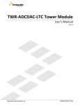
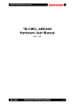
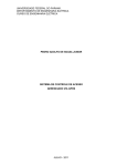
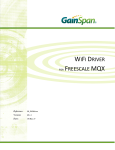
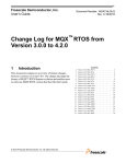
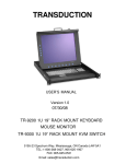
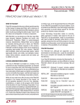
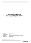
TWR-ADCDAC-LTC
Lab Guide
Rev. 0
Freescale Semiconductor Inc.
TWRADCDACLTCLAB
Contents
1 Overview .....................................................................................................................................................3
1.1 TWR-ADCDAC-LTC Hardware Overview.................................................................................................................. 3
2 References..................................................................................................................................................4
3 Hardware Configuration .......................................................................................................................4
4 TWR-MCF5225X Setup...........................................................................................................................7
4.1 CodeWarrior for ColdFire v7.2 .................................................................................................................................... 7
5 Running the Demos .............................................................................................................................. 10
5.1 Connecting to the Web Server .................................................................................................................................... 10
5.1.1 Troubleshooting the Web Server.............................................................................................................................................. 12
5.2 LTC Configuration Pages .............................................................................................................................................. 12
5.3 DAC to ADC Loopback .................................................................................................................................................... 13
5.4 Data Logger and Generator ......................................................................................................................................... 15
5.5 Thermocouple ................................................................................................................................................................... 15
TWR-ADCDAC-LTC Lab Guide
Page 2 of 16
1
Overview
This lab guide describes how to run the MQX web-enabled demonstration applications using the TWRADCDAC-LTC Tower peripheral module in combination with other Freescale Tower MCU and
peripheral modules. The guide is broken up into sections based on the Tower MCU module hardware
and development tools used.
This lab walks the user through the setup and execution of the TWR-ADCDAC-LTC Demo Suite. This
suite of software utilizes an embedded webserver to control the actions of the MCU module and the
TWR-ADCDAC-LTC analog devices. An embedded USB host is utilized to store web pages and can also
be used for data logging. A block diagram of the Demo Suite software and hardware system is shown
below. Follow the steps in the relevant sections below to setup and walk through the demo software.
Figure 1. TWR-ADCDAC-LTC Demo Suite System Overview
1.1 TWR-ADCDAC-LTC Hardware Overview
The TWR-ADCDAC-LTC is a Freescale Tower compatible high-precision analog peripheral module with
the following features:
Controllable by any Freescale Tower controller module with an SPI interface
Two Linear Technology digital-to-analog converters (DACs)
o LTC2704-16: Quad 16-bit voltage output SoftSpan™ DAC with readback
o LTC2600: Octal 16-bit rail-to-rail DACs
Two Linear Technology analog-to-digital converters (ADCs)
o LTC1859: 8-channel, 16-bit, 100 ksps SoftSpan ADC with shutdown
TWR-ADCDAC-LTC Lab Guide
Page 3 of 16
o LTC2498: 24-bit 8-/16-channel delta sigma ADC with Easy Drive™ input current
cancellation
Linear Technology voltage regulator
o LTC3471: Dual 1.3A, 1.2 MHz boost/inverter
Linear Technology voltage reference
o LTC6655-5: 0.25 ppm noise, low drift precision buffered 5V reference
Four 14-pin headers for connecting to any Linear Technology QuikEval™ demonstration board
Figure 2. TWR-ADCDAC-LTC Feature Call-outs
2
References
The documents listed below should be referenced for more information on the Freescale Tower
System and the TWR-ADCDAC-LTC. These documents can be found in the documentation tab of the
TWR-ADCDAC-LTC product page, which is linked to from www.freescale.com/tower:
TWRADCDACLTCQSG: TWR-ADCDAC-LTC Quick Start Guide
TWRADCDACLTCUM: TWR-ADCDAC-LTC User’s Manual
TWRADCDACLTCSCH: TWR-ADCDAC-LTC Schematics
3
Hardware Configuration
The hardware required to run a demo using the TWR-ADCDAC-LTC Demo Suite is:
Supported Tower MCU Module (specific instructions for setup provided in this document)
TWR-SER
TWR-ELEV
TWR-ADCDAC-LTC
USB mini-B to A adapter (provided in TWR-ADCDAC-LTC box)
TWR-ADCDAC-LTC Lab Guide
Page 4 of 16
USB Memory Stick (not provided)
Various cables and wires (provided)
Development Computer
The default jumper shunt positions for the TWR-ADCDAC-LTC are shown in Figure 3 and Table 1 below.
The Tower MCU module and TWR-SER should be set to their default settings as described in their
respective Quick Start Guides and User’s Manuals. Any deviations required from these settings will be
specifically called out in the relevant sections below.
Figure 3. TWR-ADCDAC-LTC Default Jumper Settings
Table 1. TWR-ADCDAC-LTC Default Jumper and Switch Settings
Jumper
Option
J1 - J8
QuickEval I2C/SPI Selection
J9
SPI Port Selection -- SPI_CLK
J10
SPI Port Selection -- SPI0_CSx
J11
SPI Port Selection -- SPI1_CSx
Setting
1-2
2-3
1-2
2-3
1-2
2-3
1-2
Description
2
Connect I C signals to QuickEval header
Connect SPI signals to QuickEval header
Use SPI_CLK signal from SPI0
Use SPI_CLK signal from SPI1
Select SPI0_CS0
Select SPI0_CS1
Select SPI1_CS0
TWR-ADCDAC-LTC Lab Guide
Page 5 of 16
Jumper
Option
J12
SPI Port Selection -- SPI_MOSI
J13
SPI Port Selection -- SPI_MISO
J25
SPI Port Selection -- SPI_CS
J14
SPI Chip-Select Encoding Bit 0 Setting
J15
SPI Chip-Select Encoding Bit 1 Setting
J16
SPI Chip-Select Encoding Bit 2 Setting
J28, J29
J31, J32
LTC2704 VOSx GND Connection
J30
Tower Power Connection
J34
LT3471 Shutdown
J37
LTC1859 Reference Voltage Selection
Setting
2-3
1-2
2-3
1-2
2-3
1-2
2-3
1-2
2-3
OFF
1-2
2-3
OFF
1-2
2-3
OFF
ON
OFF
ON
OFF
1-2
2-3
ON
OFF
Description
Select SPI1_CS1
Use SPI_MOSI signal from SPI0
Use SPI_MOSI signal from SPI1
Use SPI_MISO signal from SPI0
Use SPI_MISO signal from SPI1
Use SPI0_CSx (see J10)
Use SPI1_CSx (see J11)
Connected to 3.3V
Connected to GND
Driven by GPIO9
Connected to 3.3V
Connected to GND
Driven by GPIO8
Connected to 3.3V
Connected to GND
Driven by GPIO7
Connect VOSA, VOSB, VOSC, VOSD to GND
Disconnect VOSx from GND
Connect on-board 5V rail to Tower System
Isolate on-board 5V rail from Tower System
LT3471 voltage regulator enabled
LT3471 voltage regulator disabled
Use output of LTC6655-5 as reference
Use GND as reference
Assemble the Tower system consisting of the Tower MCU module, TWR-SER, and TWR-ADCDAC-LTC.
Be careful to match the Primary edge of each module to the Primary (or Functional on older systems)
TWR-ELEV module.
Make the following connections from the Tower System to the development computer:
1. USB cable between computer and the Tower MCU module power/debug USB connector
2. USB cable between the computer (or, optionally, a wall-adapter power supply) and the
USB connector on the TWR-ADCDAC-LTC
3. Serial cable from the computer to the DB9 on the TWR-SER (optional, serial cable not
included)
4. Ethernet cable between the TWR-SER and Ethernet port on computer
TWR-ADCDAC-LTC Lab Guide
Page 6 of 16
Figure 4. TWR-ADCDAC-LTC + Tower MCU Assembly (TWR-SER not pictured)
4
TWR-MCF5225X Setup
This section describes how to setup the TWR-MCF5225X as the Tower MCU module used to run the
Demo Suite and interface to the TWR-ADCDAC-LTC.
4.1 CodeWarrior for ColdFire v7.2
This section provides a walkthrough for setting up the TWR-ADCDAC-LTC Demo Suite using
CodeWarrior for ColdFire v7.2
1. Install CodeWarrior for ColdFire v7.2 – http://www.freescale.com/codewarrior
NOTE: There are different “classic” CodeWarrior Studios for ColdFire V1 family (MCF51xx, v6.3)
and ColdFire V2-V4 families (MCF52xx-MCF54xx, v7.2). CodeWarrior for Microcontrollers v10.x
is a unified version which covers all ColdFire and Kinetis MCUs.
2. Install MQX RTOS – http://www.freescale.com/mqx (latest version is 3.6.2 at the time of this
writing)
NOTE: If you are running Windows Vista or Windows 7, it is recommended that you
install MQX outside of the default C:\Program Files\ directory. Windows UAC prevents
writes to that directory if you are not running as administrator.
3. Unzip the TWR-ADCDAC-LTC Demo Suite software.
4. Open CodeWarrior for ColdFire v7.2; Click “Start Using CodeWarrior”.
TWR-ADCDAC-LTC Lab Guide
Page 7 of 16
5. The source code is provided with a pre-built binary. Therefore in most cases you should
skip directly to Step 6. However, if you need to rebuild the binary image, a modification
needs to be made to the prebuilt TWR-MCF5225X MQX BSP—a timer used by the TWRADCDAC-LTC Demo Suite is turned off by default. We need to make a change in the
configuration file and rebuild the MQX libraries:
a. Select File->Open and click “Objects of” drop down box and select “Project Files
(*.mcp)”.
b. Navigate to the config\twrmcf52259\cwcf72 directory inside the MQX installation
folder (C:\Program Files\Freescale\Freescale MQX x.x by default).
c. Open build_twrmcf52259_libs.mcp
d. Select File->Open and open config\twrmcf52259\user_config.h
e. Ensure that MQX_USE_TIMER is defined
#define MQX_USE_TIMER
1
f. Build all the libraries by clicking the Make icon:
. This step will take several
minutes to complete.
g. Close the user_config.h file and the project.
h. Select File->Open and navigate to the TWR-ADCDAC-LTC Demo Suite software
unzipped in Step 3. Click “Objects of” drop down box and select “Project Files
(*.mcp)”. Select “twradcdacltc_demosuite.mcp”.
i. Make sure the “Int Flash Debug” target is selected in the target drop-down box and
click the Make icon:
6. Connect a USB cable between your development computer and the TWR-MCF5225X
PWR/OSBDM USB connector. Choose to “Install the software automatically…” if
prompted
TWR-ADCDAC-LTC Lab Guide
Page 8 of 16
7. Open the Flash Programmer tool In CodeWarrior 7.2 by selecting Tools->Flash
Programmer from the top menu bar.
8. Click the “Load Settings” button at the bottom of the “Target Configuration” page and
select MCF52259_INTFLASH.xml—CodeWarrior will open the correct directory by
default and the correction file is the last option when files are sorted alphabetically.
TWR-ADCDAC-LTC Lab Guide
Page 9 of 16
9. Select the “Erase / Blank Check” page (left pane of the Flash Programmer window).
Select “All Sectors” and click “Erase”.
10. Select the “Program / Verify” page and click “Program”. Upon successful programming,
the status will display “Program Command Succeeded.” Close the window.
The internal flash of the MCF52259 MCU on the TWR-MCF5225X is now programmed with the
Demo Suite software. CodeWarrior can now be closed unless you wish to step through the
software.
5
Running the Demos
The TWR-ADCDAC-LTC uses an embedded web server to provide a graphical user interface with
controls for the ADCs and DACs. This section describes how to connect to the embedded web server
and demonstrate the analog interfaces.
5.1 Connecting to the Web Server
The default IP address of the Tower System is 169.254.3.3 (set in config.h in the Demo Suite). Typically,
when you connect your computer directly to the Tower, the computer will default to an auto IP
address on the same subnet as the Tower (169.254.x.x), therefore requiring no setup to the internet
connection settings on the computer. Note, the computer may take a few minutes to default to the
auto IP address and may report “Limited or No Connectivity”. Alternatively, you may configure the IP
address of the computer manually to be 169.254.3.4 with a subnet mask of 255.255.0.0. See the
Troubleshooting section below if there is an issue connecting to the embedded web server.
Follow these steps to run the embedded web server and connect to it using a web browser:
TWR-ADCDAC-LTC Lab Guide
Page 10 of 16
1. Assemble and connect the computer to the Tower System as described in section 3,
“Hardware Configuration”. Ensure that the power indicator LEDs are lit on all the
modules including the GREEN LED on the TWR-ADCDAC-LTC.
2. Program the Demo Suite software to the Tower MCU module as described in the
section above corresponding to your Tower MCU module.
3. Press the RESET button on the Tower MCU module. If connected to the serial port on
the TWR-SER module, you should see something similar in a terminal emulator:
4. Start your internet browser, disable any proxy settings, and navigate to the target
device address: 169.254.3.3.
5. You should see the web server welcome page in the browser window.
6. Copy all the files in the “usb_pages” directory of the TWR-ADCDAC-LTC Demo Suite to a
USB stick. The files should be in the root directory of the removable disk as shown in
the figure below.
TWR-ADCDAC-LTC Lab Guide
Page 11 of 16
7. Insert the USB stick into the TWR-SER module using the provided mini-B adapter.
8. Reload the Web server home page by pressing F5 in the browser window. You should
now see the “LTC Mixed Signal Board” option in the menu on the left of the screen.
5.1.1 Troubleshooting the Web Server
If you are unable to communicate from a computer to the embedded web server of the Tower System,
try the following:
1. Ensure the Tower system is assembled correctly. Each tower module has a primary and
secondary card edge connector. The primary side must be connected to the Primary (or
Functional in older systems) Elevator.
2. Ensure that the computer’s internet connection is properly configured and able to connect
to the web server. In a command window, try the ipconfig and ping commands to test the
communication with the Tower System.
3. Ensure any proxy settings in your browser are turned off.
4. Turn off any other network connections (real and virtual).
5.2 LTC Configuration Pages
A configuration page for each of the four Linear Technologies analog converter chips can be found on
the left pane of the web page under the “Configuration Pages” link. These pages provide a convenient
way to change the operational settings of the converter chips and the ability to perform simple
input/output operations to set values on the DACs or read values from the ADCs. Links to the
datasheet for the device are provided on each of their respective configuration pages.
TWR-ADCDAC-LTC Lab Guide
Page 12 of 16
5.3 DAC to ADC Loopback
The steps below describe how to setup the TWR-ADCDAC-LTC for a simple loopback from a DAC
output to an ADC input.
NOTE: Take care to only connect from the LTC2600 to the LTC2498 and and only from
the LTC2704 to the LTC1859.
1. Short the common (COM) pin input to the GND terminal for both the LTC2498 and the
LTC185 as shown in the picture below.
2. Connect a wire from channel A of the LTC2600 to channel 0 of the LTC2498
3. Connect a wire from channel A of the LTC2704 to channel 0 of the LTC1859
TWR-ADCDAC-LTC Lab Guide
Page 13 of 16
4. In the web browser, go to the LTC2600 configuration page and enter a voltage value (e.g.
“1.8”) in the “Value to Write” field. Leave the other settings at their default value as shown
below. Click the “Set / Write” button.
5. Switch to the LTC2498 configuration page. Select “Single-Ended 0” in the “Channel
Setting:” drop down box and click the “Set / Read” button. The updated voltage reading will
be displayed on the page. Verify that it is approximately the same value set as the output
on the DAC.
TWR-ADCDAC-LTC Lab Guide
Page 14 of 16
6. Repeat steps 4 and 5 above for the LTC2704 DAC and LTC1859 ADC
5.4 Data Logger and Generator
The “ADC Datalogger Config” link in the menu on the left pane of the web pages provides a utility
setup a datalogger using either of the ADCs. Instructions for using the datalogger are provided at the
top of the web page.
The samples are stored on the USB stick. After the “Set / Read” button is clicked, the “Samples Taken”
counter will increment periodically until all the requested samples have been acquired. Once
complete, you can access the log file (.csv format) over the internet connection by typing the name of
the output log file in the address bar of your browser. For example, if you left the logfile name as the
default of “output_log”, then you can access the log file by browsing to
http://169.254.3.3/usb/output_log.csv.
5.5 Thermocouple
The “Thermocouple Reader” link in the menu on the left pane provides a utility to use the LTC2498 as
a thermocouple reading device. Connect the provided thermocouple wire to the LTC2498 inputs as
shown below (yellow wire to Channel 0 and brown wire to GND) and follow the instructions on the
“Thermocouple Reader” page.
TWR-ADCDAC-LTC Lab Guide
Page 15 of 16
TWR-ADCDAC-LTC Lab Guide
Page 16 of 16