1
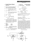
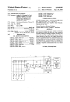
5
4,490,249
shaft support 31 extending upwardly from the valve
module. The forward (rightward) end of cam shaft 28
has a forwardly extending shank for engaging the “T”
shaped slot in the rearward end of the outwardly ex
tending shaft 320 of a gear 32 (FIG. 3). As best illus
trated in FIG. 3, gear 32 is journaled for rotation within
6
becomes disengaged from idler gear 44 so as to allow
the cam shaft to be manually rotated upon rotation of
the hub. As the hub is rotated either manually, or upon
the gear 32 being driven the motor 48, an arrow 55 on
the hub points to indicia (not shown) on the face of
cover 38 representing the various states of water soft
ener operation, to indicate which step of the regenera
the cavity 33 of a control housing 34. Returning to FIG.
2, control housing 34 is slidably secured to the forward
tion cycle is then being executed, or, whether valves are
end of the valve module 24 by a pair of support guides
presently in the service position.
36 (FIGS. 1 and 2) which each engage complimentary 10 Protruding outwardly from the gear 32 is a member
?anges (not shown) on the exterior of the control hous
56 which, as the gear rotates, comes into contact with
mg.
What has been described thus far with respect to the
the spring biased arm 57a of a leaf switch 57. Leaf
switch 57 is connected to control circuit 50 in a manner
construction and operation of the valve module 24 is
described hereinafter. The switch is actuated either by
well known in the art.
member 56 as the gear is rotated or when the hub is
The cavity 33 (FIG. 3) within the forward end of the
simply depressed since the outward force of the mem
control housing 34 is closed by a cover 38 which is
secured to the forward end of the control housing by
screws 39 (illustrated in FIGS. 1 and 3). Referring now
ber 56 keeps the spring biased arm 57a from normally
moving downwardly to actuate the switch. When
to FIG. 3 which is a frontal view of control housing 34
showing portion of cover 38 cut away, cover 38 is gen
erally opaque except for a window 40 which carries the
indicia “PM” and “WATER FLOW". As will become
switch 57 is actuated, the control circuit initiates regen
eration. Thus, regeneration can be effected not only by
manually rotating hub 52 but by simply depressing the
hub to activate switch 57.
The details of control circuit 50 are set forth schemat
ically in FIG. 4. At the heart of control circuit 50 is a
clear hereinafter by reference to FIG. 4, window 40
allows a display within the cavity to display certain 25 data processing unit 58 which, in the presently pre
information. Immediately below window 40 is a pas
ferred embodiment, takes the form of a single chip mi
sageway 41 through the cover which has a spring biased
crocomputer such as a model 8048 microcomputer as
button 42 protruding outwardly therethrough. As will
also become clear by reference to FIG. 4, button 42 is
depressed to set the time displayed by the display
through window 40.
With a portion of cover 38 broken away in FIG. 3, it
can be observed that not only is gear 32 journaled
within the cavity 33, but an idler gear 44 is also jour
manufactured by Intel Corp, Santa Clara, Calif. Mi
crocomputer 58 includes “on-board” random access
memory for storing data previously entered to the mi
crocomputer or developed during the course of opera
tion thereof. Also, the microcomputer includes on
board read only memory in which is stored the operat
ing program to be described in greater detail with re
naled within cavity 33 and is in meshing engagement 35 spect to FIGS. 5A to 5D. This program controls the
with gear 32. Idler gear 44 is driven by a gear 46 which
operation of the internal microcomputer arithmetic
is carried on the forward end of the shaft of motor 48,
logic unit which performs the necessary calculations
(FIG. 2); the motor being mounted on the rear of the
and logic ‘determinations, to decide whether regenera
control housing so that its shaft extends through the
tion should be effected. In addition to the on-board
control housing 34 and into the cavity to receive gear 40 memory and the arithmetic logic unit, microcomputer
46.
Motor 48 of FIG. 2, which is typically a 1 RPM A.C.
58 also includes an internal timer which serves as a real
cause cams 26a through 26g to actuate a corresponding
whose primary winding 60a is coupled to a supply of
time clock. For a further, more complete description of
clock motor, is energized with alternating current by a
the Model 8048 microcomputer, reference should be
control circuit 50 of FIG. 4 (described hereinafter)
had to the “MCS-48 User’s Manual” published by Intel
when the control circuit determines, in accordance with 45 Corporation.
a particular algorithm, that regeneration should be ef
A 5 volt regulated dc. voltage to energize microcom
fected. Motor 48, when energized from control circuit
puter 58 is supplied to the microcomputer at its Vcc pin
50, drives cam shaft 28 through gears 46, 44 and 32 to
by a power supply 59 comprised of a transformer 60
one of valves 250 through 25f respectively. The cams 50 110-220 volt, 50-60 Hertz a.c. supply (not shown).
26a-26f are shaped such that valves 25a through 25f
Because of the lack of space within the cavity 33 for the
respectively are actuated in a particular sequence for a
transformer, transformer 60 is mounted to the rear of
particular duration during a single revolution of the
the control housing as shown in FIG. 2. The low volt
cam shaft so that the backwash, brining, slow rinse, and
age a.c. produced across the center tapped transformer
brine re?ll and purge steps, which are normally re 55 secondary winding 60b when the primary is coupled the
quired to complete resin bed regeneration, are per
a.c. supply voltage, is rectified by a pair of diodes 61a
formed in the desired sequence. Following a single
and 6111 whose anodes are each coupled to one of oppo
revolution of the cam shaft, the valves returned to the
site ends of the transformer secondary winding 6011.
service position so as to allow normal water flow
With the diode cathodes connected together, an unreg
through the softener.
Although water softener resin bed regeneration is
normally effected when control circuit 50 energizes
ulated dc. voltage appears between the junction of the
diode cathodes, hereafter referred to as the power sup
ply unregulated voltage (unreg) output terminal and the
motor 48, there may be instances when manual regener
transformer center tap, hereinafter referred to as the
ation is desired. To enable manual regeneration, gear 32
power supply common (com) terminal.
has a hub 52 extending forwardly of the gear and 65
The unregulated dc. voltage present between the
through an opening 54 (FIG. 1) in cover 38. Gear 32
and hub 52 are spring biased from shaft 320 so that
when the hub 52 of the gear is pushed inwardly, gear 32
unregulated voltage and common terminals of power
supply is ?ltered by a pair of parallel coupled capacitors
62a and 62b before being supplied to a voltage regulator