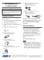
1
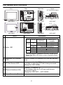
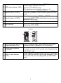
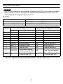
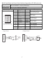
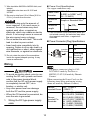
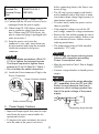
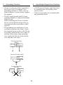
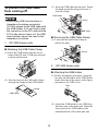
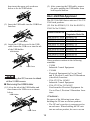
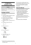
(9) USB Cable Clamp (2 port) (1 set) (Holder: 1, Cover: 2) (Only for GP-3400 Series) GP-3300/3400 Series Installation Guide Caution Be sure to read the “Warning/Caution Information” on the attached sheet before using the product. (10) USB Cable Clamp (1 port) (1) (Holder: 1, Clamp: 1) (Only for GP-3300 Series) Package Contents This unit has been carefully packed, with special attention to quality. However, should you find anything damaged or missing, please contact your local GP distributor immediately. (1) GP Unit (1) (2) English and Japanese installation Guides (1 of each) <This Guide> (3) Warning/Caution Information (1) (4) Installation Gasket (1, attached to the GP unit) (5) Installation Fasteners (Set of 4) About the Manual For the detailed information on GP3000 series, refer to the following manuals. • GP3000 Series Hardware Manual • Maintenance/Troubleshooting The manuals can be selected from the help menu of GP-Pro EX or downloaded from HVS System Home Page. URL http://www.hvssystem.com (6) RCA-BNC Convertor (1) (Only for AGP-3450T) (7) AUX Connector (1) (Only for GP-3400 Series) • When using GP-3300 Series with ProDesigner, refer to “AGP-3300 Series User Manual” (PDF File). AGP-3300 Series User Manual can be selected from [Manual] in the dialog box displayed after the CD-ROM of Pro-Designer is inserted. (8) Power Connector (1) (Attached to the GP unit for GP-3300 Series) Distribué par : System DISTRIBUTEUR CONSEIL DEPUIS 1985 2 rue René Laennec 51500 Taissy France Fax: 03 26 85 19 08, Tel : 03 26 82 49 29 1 Email : [email protected] Site web : www.hvssystem.com Part Names and Functions Front Rear Right Side B Bottom (CF Card Cover Open) F G C A AGP-3300T AGP-3300T AGP-3300T B G J AGP-3300T D F I H A C AGP-3450T E H I E AGP-3450T AGP-3450T Name J AGP-3450T Description Color Indicator ON Green A Status E LD Red Orange Flashing ON Flashing ON Flashing Logic execution mode (when logic is enabled) OFFLINE In operation RUN In operation STOP When power is turned on. In operation Major Error Backlight burnout During software startup Operation Mode (Drawing) (The logic program is disabled in the AGP-3302B/3301L/ 3301S. The Status LED turns on only in Operation Mode (Drawing).) B Expansion Unit Interface (EXT) Used to connect an expansion unit that can transmit data. C CF Card Access LED Lit in green when the CF Card is inserted and the cover is closed, or when the CF Card is being accessed. (Except for AGP-3302B) D Ethernet Interface (LAN) 10BASE-T/100BASE-TX This interface uses an RJ-45 type modular jack connector (8 pins). (Except for AGP-3301∗ / AGP-3302B) E Power Connector (Socket) - 2 F USB Host Interface (USB) Complies with USB 1.1. Uses a “TYPE-A” connector. Power supply voltage:5 VDC ±5%, Output current:500mA(max.) The maximum communication distance: 5m G Serial Interface (COM1) Dsub 9-pin plug type. RS232C, RS422, and RS485 are switched by software. (AGP-3302B supports RS232C only.) H Serial Interface (COM2) Dsub 9-pin socket type. RS422 and RS485 are supported. (AGP-3302B has Dsub 9-pin plug type and supports RS422 only.) I CF (Except for AGP-3302B) aCrd Cover Located inside the CF Card Cover. (Except for AGP-3302B) J Dip Switches Left Side K D L M AGP-3300T AGP-3450T AUX Input/Output and Sound Used for external reset, alarm output, buzzer output, K Output Interface (AUX) and sound output. (Except for GP-3300 series) L AUDIO Input Interface (L-IN/MIC) It’s an interface to which a microphone is connected. A mini jack connector (∅3.5 mm) is used. (Supported by AGP-3450T only) M VIDEO Input Interface (V-IN) It’s an interface to which a video camera is connected. NTSC (59.9 Hz) and PAL (50 Hz) are supported. A RCA connector (75Ω) is used. (Supported by AGP-3450T only) 3 General Specifications Electrical Specifications Power Supply AGP-3300∗/3301∗ AGP-3302B Input Voltage DC24V Rated Voltage DC19.2 to 28.8V Allowable Voltage Drop 5ms (max.) 10ms (max.) Power Consumption 26W (max.) 18W (max.) In-Rush Current Voltage Endurance AGP-3400∗/3450T 28W (max.) 30A (max.) AC1000V 20mA for 1minute (between charging and FG terminals) Insulation Resistance DC500V 10MΩ (min.) (between charging and FG terminals) Environmental Specifications Physical Surrounding Air Temperature 0 to +50°C*1 Storage Temperature -20 to +60°C Ambient Humidity 10 to 90% RH (Wet bulb temperature: 39°C max. - no condensation.) Storage Humidity 10 to 90% RH (Wet bulb temperature: 39°C max. - no condensation.) Dust 0.1mg/m3 and below (non-conductive levels) Pollution Degree For use in Pollution Degree 2 environment. *1 When using GP-3300 Series or STN Color LCD model in an environment where the temperature becomes or exceeds 40°C for an extended period of time, the screen contrast level may decrease from its original level of brightness. 4 External Interfaces • This GP unit’s serial port is not isolated. When the host (PLC) unit is also not isolated, and to reduce the risk of damaging the RS232C/RS422/RS485 circuit, be sure to connect the #5 SG (Signal Ground) terminal. COM1 Recommended Cable Connector XM2D-0901 <made by OMRON Corp.> Recommended Jack Screw XM2Z-0073 <made by OMRON Corp.> Recommended Cable Cover XM2S-0913 <made by OMRON Corp.> Pin # RS232C Signal Name RS422/RS485 (Except AGP-3302B) Meaning Signal Name Meaning 1 CD Carrier Detect RDA Receive Data A(+) 2 RD(RXD) Receive Data RDB Receive Data B(-) 3 SD(TXD) Send Data SDA Send Data A(+) 4 ER(DTR) Data Terminal Ready ERA Data Terminal Ready A(+) 5 SG Signal Ground SG Signal Ground 6 DR(DSR) Data Set Ready CSB Clear to Send B(-) 7 RS(RTS) Request to Send SDB Send Data B(-) 8 CS(CTS) Clear to Send CSA Clear to Send A(+) CI(RI)/VCC Called status display/ ERB +5V±5% Output 0.25A*1 Data Terminal Ready B(-) FG Frame Ground (Common with SG) Frame Ground (Common with SG) 9 Shell FG *1 The RI/VCC selection for Pin #9 is switched via software. The VCC output is not protected against overcurrent. To prevent damage or unit malfunctions, use only the rated current. 5 COM2 Recommended Cable Connector XM2A-0901 <made by OMRON Corp.> Recommended Jack Screw XM2Z-0073 <made by OMRON Corp.> XM2D-0901 <made by OMRON Corp.> (AGP-3302B only) Recommended Cable Cover XM2S-0913 <made by OMRON Corp.> Pin # 1 RS422/RS485 (Except AGP-3302B) Signal Name TRMRX Meaning RS422 (AGP-3302B only) Signal Name Termination (Receiver side: 100Ω) RDA Meaning Receive Data A(+) 2 RDA Receive Data A(+) RDB Receive Data B(-) 3 SDA Send Data A(+) SDA Send Data A(+) Data Terminal Ready A(+) 4 RS(RTS) Request for Send ERA 5 SG Signal Ground SG 6 VCC +5V±5% Output 0.25A*1 CSB 7 RDB Receive Data B(-) SDB Send Data B(-) 8 SDB Send Data B(-) CSA Clear to Send A(+) 9 TRMTX Termination (Receiver side: 100Ω) ERB Data Terminal Ready B(-) FG Frame Ground (Common with SG) FG Frame Ground (Common with SG) Shell Signal Ground Clear to Send B(-) *1 The VCC output for Pin #6 is not protected against overcurrent. To prevent damage or unit malfunctions, use only the rated current. 6 AUX Input/Output and Sound Output Interface (Supported by GP-3400 series only) Recommended S2L3.5/12/90F90F <made by Weidmuller> Cable Connector Terminal Block B2L3.5/12LH <made by Weidmuller> Pin Arrangement 1 11 Pin# 2 12 (Cable connection side) Signal Name RESET IN_A Input 2 RESET IN_B Input 3 RUN+ Output 4 RUN- Output 5 ALARM+ Output 6 ALARM- Output 7 BUZZER+ Output 8 BUZZER- Output Meaning External Reset Input RUN Signal ALARM Signal Buzzer Signal 9 NC - Not Connected 10 NC - Not Connected 11 SP Output Speaker Out 12 SP_GND Output Speaker Ground • Output Circuit 1.2kΩ Internal Circuit • Input Circuit Internal Circuit Direction 1 DC 24V 5.4kΩ 470pF 10kΩ 7 + Load DC 24V - 2. Installations 1. GP Installation (1) Create a Panel Cut and insert the GP into the panel from the front. Installation Requirements Unit: mm [in.] X Unit:mm[in.] 100 [3.94] GP 100 [3.94] 100 [3.94] 100 [3.94] 100 [3.94] GP 100 [3.94] 100 [3.94] X Y Panel thickness +1 +1 GP156.0 -0 123.5 -0 1.6[0.06] 3300 to +0.04 +0.04 Series [6.14 ] [4.86 ] 5.0[0.20] -0 -0 • Be sure that the surrounding air temperature and the ambient humidity are within their designated ranges. (Surrounding air temperature: 0 to 50°C, Ambient humidity: 10 to 90%RH, Wet bulb temperature: 39°C max.) When installing the GP on the panel of a cabinet or enclosure, “Surrounding air temperature” indicates both the panel face and cabinet or enclosure’s internal temperature. Panel Face Under 4-R3 Panel thickness [0.12] Y • For easier maintenance, operation, and improved ventilation, be sure to install the GP at least 100 mm [3.94 in.] away from adjacent structures and other equipment. +1 +1 GP204.5 -0 159.5 -0 1.6[0.06] 3400 to +0.04 +0.04 Series [8.05 ] [6.28 ] 10.0[0.39] -0 -0 (2) Confirm that the installation gasket is attached to the GP unit and then place the GP unit into the Panel from the front. • It is strongly recommended that you use the installation gasket, since it absorbs vibration in addition to repelling water. For the procedure for replacing the installation gasket, refer to “GP3000 Series Hardware Manual”. (3) The following figures show the four (4) fastener insertion slot locations. Insert each fastener’s hook into the slot and tighten it with a screwdriver. Insert the installation fasteners securely into the insertion slot recess. Inside Cabinet • Be sure that heat from surrounding equipment does not cause the GP to exceed its standard operating temperature. 8 Items Required to Wire Connectors TOP [Screwdriver] Recommended type: SDI (Product No. 900837) <Weidmuller Japan> If another manufacturer is used, be sure the part has the following dimensions: point depth: 0.4mm [0.02in.] point height: 2.5mm [0.10in.] length from the point to the handle: 80mm [3.15in.] Point shape should be DIN5264A, and meet Security Standard DN EN60900. Also, the screwdriver’s tip should be flat as indicated in order to access the narrow hole of the connector: Insertion Slots Bottom (The figure shows the GP-3300 series.) Insertion Slot Recess Hook the fastener on the Recess, Panel Installation Fastener Screwdriver Tip Shape GP Hook and secure the fastener on the panel with a screw. Detachment Turn the tabs on the levers at both ends of the connector, and the connector is released from the GP. • Tightening the screws with too much force can damage the GP unit’s plastic case. • The necessary torque is 0.5N•m. 3. Wiring and attachment (1) Insert the tip of the screwdriver into one of the square holes. Then, insert the cable into the corresponding round hole. When you pull out the screwdriver, the cable is locked. For the pin assignment of the AUX connector, refer to “External Interfaces”. Wiring and attaching/detaching the AUX connector (GP-3400 series only) Wire*1 *2 • Be sure to remove the AUX Connector from the GP unit prior to starting wiring. Failure to do so may cause an electric shock. Screwdriver*3 (2) Insert the wired AUX connector into the auxiliary I/O or sound output interface (AUX) on the left side of the GP unit on. If the connector cannot be fully inserted, turn the tabs on the levers at both ends of the connector in the reverse direction and insert the connector. 9 Power Cord Specifications Use copper conductors only *1 Wire should be AWG22 to AWG18 thick, and twisted. Applicable wire sizes are UL1015 and UL1007. 0.2 to 2.5mm2 Power Cord [0.0001 to 0.0097 inch2] Diameter (24 - 12 AWG) *2 Be sure to strip from 6.5 to 8.0mm [0.26 to 0.31in.] of cover from the wire. Conductor Type • Be sure to strip only the amount of cover required. If too much cover is removed, the end wires may short against each other, or against an electrode, which can create an electric shock. If not enough cover is removed the wire cannot carry a charge. • Do not solder the wire itself. This could lead to a bad or poor contact. • Insert each wire completely into its opening. Failure to do so can lead to a unit malfunction or short, either against wire filaments, or against an electrode. 7 mm [0.28in] Conductor Length *1 If the Conductor’s end (individual) wires are not twisted correctly, the end wires may either short against each other, or against an electrode. Power Connector (Plug) Specifications + FG *3 Do not rotate the point of the screwdriver inside the square-shaped opening. It may cause a malfunction. Wiring Insertion Direction + 24V - 0V Grounding Terminal FG connected to the GP chassis • The power connector (plug) is CA5DCCNM-01 made by Pro-face or MSTB2,5/3-ST-5,08 made by Phoenix Contact. When connecting the Power Cord, use the following items when performing wiring. (Items are made by Phoenix Contact.) • To avoid an electric shock, prior to connecting the GP unit’s power cord terminals to the power terminal block, confirm that the GP unit’s power supply is completely turned OFF, via a breaker, or similar unit. • Any other power level can damage both the GP and the power supply. • When the FG terminal is connected, be sure the wire is grounded. 1. Simple or Stranded Wire*1 RecomSZF 1-0.6x3.5 mended Driver (1204517) Recommended Pin Terminals Wiring the DC type power supply cable 10 AI 0.25-6BU (3201291) AI 0.34-8TQ (3200865) AI 0.5-8WH (3200014) AI 0.75-8GY (3200519) AI 1-8RD (3200030) AI 1.5-8BK (3200043) AI 2.5-8BU (3200522) RecomCRIMPFOX ZA 3 mended Pin Terminal Crimp (1201882) Tool • Connecting the GP Power Cord (1) Confirm that the GP unit’s Power Cord is unplugged from the power supply. (2) When using GP-3300 Series, remove the power connector (plug) from the main unit. (When using GP-3400 Series, the power connector (plug) is packaged with other accessories.) (3) Strip the power cord, twist the conductor’s wire ends, insert them into the pin terminal and crimp the terminal. Attach the terminal to the power connector. • • • • • Use voltage and noise reducing transformers with capacities exceeding Power Consumption value. • Use a flat-blade screwdriver (Size 0.6 X 3.5) to tighten the terminal screws. The torque required to tighten these screws is 0.5 to 0.6 N•m [5-7 Lb•In.]. • Do not solder the cable connection. (4) Attach the Power connector (Plug) to the Power Connector. - + before connecting them to the Power connector (Plug). The GP unit’s power supply cord should not be bundled with or kept close to main circuit lines (high voltage, high current), or input/output signal lines. To reduce noise, make the power cord as short as possible. If the supplied voltage exceeds the GP unit’s range, connect a voltage transformer. Between the line and the ground, be sure to use a low noise power supply. If there is an excess amount of noise, connect a noise reducing transformer. The temperature rating of field installed conductors: 75oC only. • Must be used with a Class 2 Power Supply. (24VDC) • Connect a surge absorber to handle power surges. Power Connector (Socket) • Be sure to ground the surge absorber (E1) separately from the GP unit (E2). Select a surge absorber that has a maximum circuit voltage greater then that of the peak voltage of the power supply. FG GP FG Power connector (Plug) 2. E1 Power Supply Cautions E2 Lightening Surge Absorber • Input and Output signal lines must be separated from the power control cables for operational circuits. • To improve the noise resistance, be sure to twist the ends of the power cord wires 11 3. Grounding Cautions 4. • Be sure to create an exclusive ground for the Power Cord’s FG terminal. Use a grounding resistance of 100Ω, a wire of 2mm2 or thicker, or your country’s applicable standard. • The SG (signal ground) and FG (frame ground) terminals are connected internally in the GP unit. When connecting the SG line to another device, be sure that the design of the system/connection does not produce a shorting loop. • The grounding wire should have a cross sectional area greater then 2mm2. Create the connection point as close to the GP unit as possible, and make the wire as short, as possible. When using a long grounding wire, replace the thin wire with a thicker wire, and place it in a duct. • All GP Input and Output signal lines must be separated from all operating circuit (power) cables. • If this is not possible, use a shielded cable and ground the shield. Exclusive Grounding (BEST) GP unit Other Equipment Common Grounding (OK) GP unit Other Equipment Common Grounding (Not OK) GP unit Input/Output Signal Line Cautions Other Equipment 12 (3) Insert the USB cable into the port. Fasten the band around the plug and secure it with the clamp. To prevent the USB cable from coming off USB Holder Clamp • When using USB Host Interface in Hazardous Locations provided in UL1604, please fix the USB cable with the USB Holder. If it’s not fixed so that the connector on the GP’s side and the PLC’s side cannot come out, the USB Host Interface cannot be used in the Hazardous Locations. 1. USB Cable Removing the USB Cable Clamp (1) Lower the tab and lift the clamp to release the plug. GP-3300 Series units Attaching the USB Cable Clamp Clamp (1) Insert the USB holder into the slot in front of the GP unit’s USB port and pull it down and forward. Tab 2 2. 1 GP-3400 Series units Attaching the USB Holder (1) Before starting the procedure, orient the two tabs on both sides of the USB Holder in the direction of the arrows in the figure and remove the USB Cover. (2) Pass the band of the USB cable clamp through the bridge of the USB holder. Tabs Bridge USB Holder (2) Attach the USB holder to the USB Host Interface part of the main unit. Hook the lower pick of the USB holder to the attachment hole of the main unit and 13 then insert the upper pick as shown below to fix the USB holder. (2) After removing the USB cable, remove the picks pushing the USB holder from both top and bottom. UL/c-UL/CSA Approval The GP-3300/3400 Series units are UL/c-UL/ CSA listed products. (UL File No.E220851, UL File No.E182139, CSA File No.219866) (3) Insert the USB cable into the USB Host Interface. USB Cable (4) Attach the USB cover to fix the USB cable. Insert the USB cover into the tab of the USB holder. USB Holder Tab Product Model No. UL/c-UL/CSA Registration Model No. AGP3300-L1-D24 AGP3300-S1-D24 AGP3300-T1-D24 AGP3301-L1-D24 AGP3301-S1-D24 AGP3302-B1-D24 AGP3400-T1-D24 AGP3400-S1-D24 AGP3450-T1-D24 3280007-03 3280007-02 3280007-01 3280007-13 3280007-12 3280007-24 3280035-01 3280035-02 3280035-31 These products conform to the following standards: • UL508 Industrial Control Equipment • UL1604 Electrical Equipment for Use in Class I and II, Division 2, and Class III Hazardous (classified) Locations • CSA-C22.2 No.14-M95 Industrial Control Equipment • CSA-C22.2 No.213-M1987 Non-Incendive Electrical Equipment for Use in Class I, Division 2 Hazardous Locations USB Cover • When using the GP, be sure to attach all the 2 USB covers. Removing the USB Holder (1) Lift up the tab of the USB holder and then remove the USB cover as shown below. USB Holder <Cautions> Tab Be aware of the following items when building the GP into an end-use product: • The GP unit’s rear face is not approved as an enclosure. When building the GP unit into an end-use product, be sure to use an USB Cover 14 • • • • • enclosure that satisfies standards as the end-use product’s overall enclosure. The GP unit must be used indoors only. Install and operate the GP with its front panel facing outwards. If the GP is mounted so as to cool itself naturally, be sure to install it in a vertical panel. Also, it’s recommended that the GP should be mounted at least 100mm away from any other adjacent structures or machine parts. The temperature must be checked on the final product in which the GP is installed. Serial Interface (COM2) is not Limited Power Source. For use on a flat surface of a Type 4X (Indoor Use Only) and/or Type 13 Enclosure. (5) WARNING: Explosion hazard-confirm that the power supply has been turned OFF before disconnecting equipment, or confirm that the location is not subject to the risk of explosion. (6) “WARNING: Explosion hazard-do not disconnect equipment unless power has been switched off or the area is known to be Non-Hazardous”, and “AVERTISSEMENT: RISQUE D’EXPLOSION-AVANT DE DECONNECTER L’EQUIPEMENT, COUPER LE COURANT OU S’ASSURER QUE L’EMPLACEMENT EST DESIGNE NON DANGEREUX”. (7) In the case of use in Hazardous Locations, be sure to check that the externally connected unit and each interface have been fixed with screws and locked. In Hazardous Locations, it’s impossible to insert or pull the cable from the applicable port. Be sure to check that the location is Non-Hazardous before inserting or pulling it. UL1604/CSA-C22.2, No.213 Compliance and Handling Cautions (1) Power and input/output wiring must be in accordance with Class I, Division 2 wiring methods - Article 501-4(b) of the National Electrical Code, NFPA 70 within the United States, and in accordance with Section 18-152 of the Canadian Electrical Code for units installed within Canada. (2) Suitable for use in Class I, Division 2, Groups A, B, C, and D Hazardous Locations, or Non-Hazardous Locations only. (3) “WARNING: Explosion hazardsubstitution of components may impair suitability for Class I, Division 2”, and “AVERTISSEMENT: RISQUE D’EXPLOSION-LA SUBSTITUTION DE COMPOSANTS PEUT RENDRE CE MATERIAL INACCEPTABLE POUR LES EMPLACEMENTS DE CLASSE I, DIVISION2”. (4) WARNING: Explosion hazard-when in hazardous locations, turn OFF power before replacing or wiring modules. CE Marking • The AGP3300-L1-D24/AGP3300-S1D24/AGP3300-T1-D24/AGP3301-L1D24/AGP3301-S1-D24/AGP3302-B1D24/AGP3400-S1-D24/AGP3400-T1D24/AGP3450-T1-D24 units are CE marked, EMC compliant products. These units also conform to EN55011 Class A, EN61000-6-2 directives. 15 Inquiry Do you have any questions about difficulties with your GP? Please access our site anytime that you need help with a solution. http://www.pro-face.com/otasuke/ Note Please be aware that Digital Electronics Corporation shall not be held liable by the user for any damages, losses, or third party claims arising from the uses of this product. Digital Electronics Corporation 8-2-52 Nanko-higashi Suminoe-ku, Osaka 559-0031 JAPAN TEL: +81-(0)6-6613-3116 FAX: +81-(0)6-6613-5888 http://www.proface.com © Copyright 2005 Digital Electronics Corporation. All rights reserved. 070220K .AGP3300/3400-MT02E-BTH 2006.11 JM/C 16