1
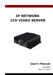
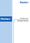
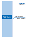
(9) USB Cable Clamp (2 port) (1 set) (Holder: 1, Cover: 2) (GP-3400 Series) GP-3300/3400 Series Installation Guide Caution (10)USB Cable Clamp (1 port) (1) (Holder: 1, Clamp: 1) (All GP-3300 Series, except AGP-3310T/3360T) Be sure to read the “Warning/Caution Information” on the attached sheet before using the product. Package Contents (11) USB Cable Clamp (1 port) (Clip: 2, Tie: 2) (AGP-3310T/3360T) (1) GP Unit (1) (2) English and Japanese installation Guides (1 of each) <This Guide> (3) Warning/Caution Information (1) (4) Installation Gasket (1, attached to the GP unit) (5) Installation Fasteners (Set of 4) This unit has been carefully packed, with special attention to quality. However, should you find anything damaged or missing, please contact your local GP distributor immediately. (6) RCA-BNC Convertor (1) (AGP-3360T/AGP-3450T) About the Manual For the detailed information on GP3000 series, refer to the following manuals. • GP3000 Series Hardware Manual • Maintenance/Troubleshooting The manuals can be selected from the help menu of GP-Pro EX or downloaded from Pro-face Home Page. URL http://www.pro-face.com/otasuke/ (7) AUX Connector (1) (GP-3400 Series) (8) Power Connector (1) (Attached to the GP unit for GP-3300 Series) • When using GP-3300 Series with ProDesigner, refer to “AGP-3300 Series User Manual” (PDF File). AGP-3300 Series User Manual can be selected from [Manual] in the [Install] dialog box displayed after the CD-ROM of ProDesigner is inserted. 1 Part Names and Functions Front Rear Right Side B Bottom (CF Card Cover Open) F G C A AGP-3300T AGP-3300T C D F I E J AGP-3450T AGP-3450T Name A Status LED G J AGP-3300T H A AGP-3450T E H AGP-3300T B I AGP-3450T Description Mode Logic execution mode Color Indicator Operation (Drawing) (when logic is enabled) OFFLINE ON Green In operation RUN Flashing In operation STOP ON When power is turned on. Red Flashing In operation Major Error ON Backlight burnout or GP malfuction *1 Orange Flashing During software startup *1 When backlight replacement or repair of the GP is required, please contact your local GP distributor. (The logic program is disabled in the AGP-3302B/3301L/3301S. The Status LED turns on only in Operation Mode (Drawing).) B Expansion Unit Interface (EXT) Used to connect an expansion unit that can transmit data. Lit in green when the CF Card is inserted and the cover C CF Card Access LED is closed, or when the CF Card is being accessed. (Except for AGP-3302B) 10BASE-T/100BASE-TX This interface uses an RJ-45 type modular jack D Ethernet Interface (LAN) connector (8 pins). (Except for AGP-3301∗ / AGP-3302B) E Power Connector (Socket) 2 Complies with USB 1.1. Uses a “TYPE-A” connector. Power supply voltage:5 VDC ±5 %, Output current:500 mA(max.) The maximum communication distance: 5m D-sub 9-pin plug type. RS232C, RS422, and RS485 are switched by software. (AGP-3302B supports RS232C only.) D-sub 9-pin socket type. RS422 and RS485 are supported. (AGP-3302B has D-sub 9-pin plug type and supports RS422 only.) (Except for AGP-3302B) Located inside the CF Card Cover. (Except for AGP-3302B) F USB Host Interface (USB) G Serial Interface (COM1) H Serial Interface (COM2) I CF Card Cover J Dip Switches Left Side K L M D AGP-3300T AGP-3450T AUX Input/Output and Sound Used for external reset, alarm output, buzzer output, K Output Interface (AUX) and sound output. (Except for GP-3300 series) It’s an interface to which a microphone is connected. A AUDIO Input Interface L mini jack connector (∅3.5 mm) is used. (Supported by (L-IN/MIC) AGP-3360T/AGP-3450T only) It’s an interface to which a video camera is connected. VIDEO Input Interface NTSC (59.9 Hz) and PAL (50 Hz) are supported. A RCA M (V-IN) connector (75 Ω) is used. (Supported by AGP-3360T/ AGP-3450T only) Speaker Output Interface A mini jack connector (∅3.5 mm) is used. (Supported N (SPEAKER OUT) by AGP-3310T/AGP-3360T only) • The following is each part for the AGP-3310T/3360T. I B C J N D F L M A E AGP-3360T Front F AGP-3360T Rear 3 G H AGP-3360T Bottom AGP-3360T Right Side General Specifications Electrical Specifications Power Supply AGP-3300∗/3301∗/ 3310T/3360T AGP-3302B Input Voltage DC 24 V Rated Voltage DC 19.2 to 28.8 V Allowable Voltage Drop 5 ms (max.) 10 ms (max.) Power Consumption 26 W (max.) 18 W (max.) In-Rush Current 30 A (max.) Voltage Endurance AGP-3400∗/3450T 28 W (max.) AC 1000 V 20 mA for 1 minute (between charging and FG terminals) Insulation Resistance DC 500 V 10 MΩ (min.) (between charging and FG terminals) Environmental Specifications Physical Surrounding Air Temperature Storage Temperature Ambient Humidity Storage Humidity Dust Pollution Degree 0 to 50 °C*1 -20 to +60 °C 10 to 90 % RH (Wet bulb temperature: 39 °C max. - no condensation.) 10 to 90 % RH (Wet bulb temperature: 39 °C max. - no condensation.) 0.1 mg/m3 and below (non-conductive levels) For use in Pollution Degree 2 environment. *1 When using a model with a monochrome LCD or a STN Color LCD model in an environment where the temperature is 40 °C or higher for an extended period of time, the screen contrast level may decrease from its original level of brightness. 4 External Interfaces • For instructions on how to connect to other devices, always refer to the “GP-Pro EX Device/PLC Connection Manual”. • Always connect the #5 SG (Signal Ground) of the GP unit to the connected device, especially if the connected device is also not isolated. Failure to do so may damage the RS232C/RS422/RS485 circuit. COM1 Recommended Cable Connector XM2D-0901 <made by OMRON Corp.> Recommended Jack Screw XM2Z-0073 <made by OMRON Corp.> Recommended Cable Cover XM2S-0913 <made by OMRON Corp.> Fitting fastener #4-40 (UNC) Pin # RS232C Signal Name 1 CD 2 3 4 RS422/RS485 (Except AGP-3302B) Meaning Signal Name Meaning Carrier Detect RDA RD(RXD) Receive Data RDB Receive Data B(-) SD(TXD) Send Data SDA Send Data A(+) ER(DTR) Data Terminal Ready ERA Data Terminal Ready A(+) 5 SG Signal Ground SG Signal Ground 6 DR(DSR) Data Set Ready CSB Clear to Send B(-) 7 RS(RTS) Request to Send SDB Send Data B(-) 8 CS(CTS) Clear to Send CSA Clear to Send A(+) CI(RI)/VCC Called status display/ ERB +5 V ±5 % Output 0.25 A*1 Data Terminal Ready B(-) FG Frame Ground (Common with SG) Frame Ground (Common with SG) 9 Shell FG Receive Data A(+) *1 The RI/VCC selection for Pin #9 is switched via software. The VCC output is not protected against overcurrent. To prevent damage or unit malfunctions, use only the rated current. 5 COM2 • Always connect close to the GP unit's COM port when terminating with the termination pins (TRMRX/TRMTX). Recommended Cable Connector XM2A-0901 <made by OMRON Corp.> Recommended Jack Screw XM2Z-0073 <made by OMRON Corp.> XM2D-0901 <made by OMRON Corp.> (AGP-3302B only) Recommended Cable Cover XM2S-0913 <made by OMRON Corp.> Fitting fastener Pin # #4-40 (UNC) RS422/RS485 (Except AGP-3302B) Signal Name Meaning RS422 (AGP-3302B only) Signal Name Meaning 1 TRMRX Termination (Receiver side: 100 Ω) 2 RDA Receive Data A(+) RDB Receive Data B(-) 3 SDA Send Data A(+) SDA Send Data A(+) 4 RS(RTS) Request for Send ERA Data Terminal Ready A(+) 5 SG Signal Ground SG 6 VCC +5 V ±5 % Output 0.25 A*1 CSB 7 RDB Receive Data B(-) SDB Send Data B(-) 8 SDB Send Data B(-) CSA Clear to Send A(+) 9 TRMTX Termination (Receiver side: 100 Ω) ERB Data Terminal Ready B(-) FG Frame Ground (Common with SG) FG Frame Ground (Common with SG) Shell RDA Receive Data A(+) Signal Ground Clear to Send B(-) *1 The VCC output for Pin #6 is not protected against overcurrent. To prevent damage or unit malfunctions, use only the rated current. 6 AUX Input/Output and Sound Output Interface (Supported by GP-3400 series only) GP Unit Side Connector S2L3.5/12/90F <made by Weidmuller> Terminal Block B2L3.5/12LH <made by Weidmuller> Pin Arrangement 1 11 Pin# 2 12 (Cable connection side) Signal Name RESET IN_A Input 2 RESET IN_B Input 3 RUN+ Output 4 RUN- Output 5 ALARM+ Output 6 ALARM- Output 7 BUZZER+ Output 8 BUZZER- Output Meaning External Reset Input RUN Signal ALARM Signal Buzzer Signal 9 NC - Not Connected 10 NC - Not Connected 11 SP Output Speaker Out 12 SP_GND Output Speaker Ground • Output Circuit 1.2 kΩ Internal Circuit • Input Circuit Internal Circuit Direction 1 DC 24 V 5.4 kΩ + 470 pF 10 kΩ 7 Load DC 24 V - Unit: mm [in.] Installations Installation Requirements Y 1. Panel r≤3 [0.12] thickness X • For easier maintenance, operation, and improved ventilation, be sure to install the GP at least 100 mm [3.94 in.] away from adjacent structures and other equipment. GP Unit:mm[in.] 100 [3.94] GP 100 [3.94] 100 [3.94] GP-3300 Series 100 [3.94] 100 [3.94] GP-3400 Series 100 [3.94] 100 [3.94] Y +1 156.0 -0 +1 123.5 -0 +1 204.5 -0 +1 159.5 -0 Panel thickness 1.6 [0.06] to +0.04 +0.04 [6.14-0 ] [4.86-0 ] 5.0 [0.20] 1.6 [0.06] to +0.04 10.0 [0.39] [8.05-0 ] [6.28+0.04 ] -0 (2) Confirm that the installation gasket is attached to the GP unit and then place the GP unit into the Panel from the front. • Be sure that the surrounding air temperature and the ambient humidity are within their designated ranges. (Surrounding air temperature: 0 to 50 °C, Ambient humidity: 10 to 90 %RH, Wet bulb temperature: 39 °C max.) When installing the GP on the panel of a cabinet or enclosure, “Surrounding air temperature” indicates both the panel face and cabinet or enclosure’s internal temperature. Panel Face X • It is strongly recommended that you use the installation gasket, since it absorbs vibration in addition to repelling water. For the procedure for replacing the installation gasket, refer to “GP3000 Series Hardware Manual”. (3) The following figures show the four (4) fastener insertion slot locations. Insert each fastener’s hook into the slot and tighten it with a screwdriver. Insert the installation fasteners securely into the insertion slot recess. Inside Cabinet TOP Insertion Slots • Be sure that heat from surrounding equipment does not cause the GP to exceed its standard operating temperature. 2. Bottom (The figure shows the GP-3300 series.) GP Installation (1) Create a Panel Cut and insert the GP into the panel from the front. 8 Wiring and attachment Insertion Slot Recess (1) Insert the tip of the screwdriver into one of the square holes. Then, insert the cable into the corresponding round hole. When you pull out the screwdriver, the cable is locked. For the pin assignment of the AUX connector, refer to “External Interfaces”. Hook the fastener on the Recess, Panel GP Installation Fastener Hook and secure the fastener on the panel with a screw. Wire*1 *2 • Tightening the screws with too much force can damage the GP unit’s plastic case. • The necessary torque is 0.5 N•m. 3. Screwdriver*3 (2) Insert the wired AUX connector into the auxiliary I/O or sound output interface (AUX) on the left side of the GP unit on. If the connector cannot be fully inserted, turn the tabs on the levers at both ends of the connector in the reverse direction and insert the connector. Wiring and attaching/detaching the AUX connector (GP-3400 series only) • Be sure to remove the AUX Connector from the GP unit prior to starting wiring. Failure to do so may cause an electric shock. *1 Wire should be AWG 22 to AWG 18 thick, and twisted. Applicable wire sizes are UL1015 and UL1007. Items Required to Wire Connectors *2 Be sure to strip from 6.5 to 8.0 mm [0.26 to 0.31 in.] of cover from the wire. [Screwdriver] Recommended type: SDI (Product No. 900837) <Weidmuller Japan> If another manufacturer is used, be sure the part has the following dimensions: point depth: 0.4 mm [0.02 in.] point height: 2.5 mm [0.10 in.] length from the point to the handle: 80 mm [3.15 in.] Point shape should be DIN5264A, and meet Security Standard DN EN60900. Also, the screwdriver’s tip should be flat as indicated in order to access the narrow hole of the connector: • Be sure to strip only the amount of cover required. If too much cover is removed, the end wires may short against each other, or against an electrode, which can create an electric shock. If not enough cover is removed the wire cannot carry a charge. • Do not solder the wire itself. This could lead to a bad or poor contact. • Insert each wire completely into its opening. Failure to do so can lead to a unit malfunction or short, either against wire filaments, or against an electrode. Screwdriver Tip Shape Detachment *3 Do not rotate the point of the screwdriver inside the square-shaped opening. It may cause a malfunction. Turn the tabs on the levers at both ends of the connector, and the connector is released from the GP. 9 Wiring • The power connector (plug) is CA5DCCNM-01 made by Pro-face or MSTB2,5/3-ST-5,08 made by Phoenix Contact. When connecting the Power Cord, use the following items when performing wiring. (Items are made by Phoenix Contact.) • To avoid an electric shock, prior to connecting the GP unit’s power cord terminals to the power terminal block, confirm that the GP unit’s power supply is completely turned OFF, via a breaker, or similar unit. • Any other power level can damage both the GP and the power supply. • When the FG terminal is connected, be sure the wire is grounded. 1. Wiring the DC Type Power Cord Recomended Driver SZF 1-0.6x3.5 (1204517) Recomended Pin Terminals AI 0.75-8GY (3200519) AI 1-8RD (3200030) AI 1.5-8BK (3200043) AI 2.5-8BU (3200522) Recomended Pin Terminal Crimp Tool CRIMPFOX ZA 3 (1201882) Power Cord Specifications Connecting the GP Power Cord Use copper conductors only (1) Confirm that the GP unit’s Power Cord is unplugged from the power supply. (2) When using GP-3300 Series, remove the power connector (plug) from the right side of the main unit (the rear face for the AGP-3310T/ 3360T). (When using GP-3400 Series, the power connector (plug) is packaged with other accessories.) (3) Strip the power cord, twist the conductor’s wire ends, insert them into the pin terminal and crimp the terminal. Attach the terminal to the power connector. Power Cord 0.75 to 2.5 mm2 Diameter (18 - 12 AWG) Conductor Type Simple or Stranded Wire*1 7 mm [0.28 in] Conductor Length *1 If the Conductor’s end (individual) wires are not twisted correctly, the end wires may either short against each other, or against an electrode. Power Connector (Plug) Specifications + + FG Insertion Direction 24 V 0V • Use a flat-blade screwdriver (Size 0.6 X 3.5) to tighten the terminal screws. The torque required to tighten these screws is 0.5 to 0.6 N•m [5-7 Lb•In.]. • Do not solder the cable connection. Grounding Terminal FG connected to the GP chassis 10 (4) Attach the Power connector (Plug) to the GP. - + • Be sure to ground the surge absorber (E1) separately from the GP unit (E2). Select a surge absorber that has a maximum circuit voltage greater then that of the peak voltage of the power supply. Power Connector (Socket) FG GP FG E1 Power connector (Plug) 2. AGP-3300T E2 Lightening Surge Absorber Power Supply Cautions 3. • Input and Output signal lines must be separated from the power control cables for operational circuits. • To improve noise resistance, be sure to twist the ends of the power cord wires before connecting them to the Power connector (Plug). • The GP unit’s power supply cord should not be bundled with or kept close to main circuit lines (high voltage, high current), or input/output signal lines. • To reduce noise, make the power cord as short as possible. • If the supplied voltage exceeds the GP unit’s range, connect a voltage transformer. • Be sure to use a low noise power supply between the line and the ground. If there is an excess amount of noise, connect a noise reducing transformer. • The temperature rating of field installed conductors: 75 oC only. Grounding Cautions • Be sure to create an exclusive ground for the Power Cord’s FG terminal. Use a grounding resistance of 100 Ω , a wire of 2 mm2 or thicker, or your country’s applicable standard. • The SG (signal ground) and FG (frame ground) terminals are connected internally in the GP unit. When connecting the SG line to another device, be sure that the design of the system/connection does not produce a shorting loop. • The grounding wire should have a cross sectional area greater then 2 mm2. Create the connection point as close to the GP unit as possible, and make the wire as short, as possible. When using a long grounding wire, replace the thin wire with a thicker wire, and place it in a duct. Exclusive Grounding (BEST) GP unit • Use voltage and noise reducing transformers with capacities exceeding Power Consumption value. • Must be used with a Class 2 Power Supply. (24 VDC) • Connect a surge absorber to handle power surges. 11 Other Equipment 1. Common Grounding (OK) GP unit Other Equipment GP-3300 Series units (Except for AGP-3310T/AGP-3360T) Attaching the USB Cable Clamp (1) Insert the USB holder into the slot in front of the GP unit’s USB port and pull it down and forward. Common Grounding (Not OK) GP unit 4. 2 Other Equipment 1 (2) Pass the band of the USB cable clamp through the bridge of the USB holder. Input/Output Signal Line Cautions • All GP Input and Output signal lines must be separated from all operating circuit (power) cables. • If this is not possible, use a shielded cable and ground the shield. Bridge USB Holder (3) Insert the USB cable into the port. Fasten the band around the plug and secure it with the clamp. Securing the USB cable connection USB Holder Clamp • When using USB Host Interface in Hazardous Locations, please fix the USB cable with the USB Holder. If it’s not fixed so that the connector on the GP’s side and the PLC’s side cannot come out, the USB Host Interface cannot be used in the Hazardous Locations. USB Cable Removing the USB Cable Clamp (1) Lower the tab and lift the clamp to release the plug. Clamp Tab 12 2. AGP-3310T/3360T units can pass through the center of the tie loop. • Be careful for the edge of the clip not to cut the fingers. Attaching the USB Cable Clip (1) Mount the clip to the USB mark connector shell so that it overlaps. The clip is corresponding to 27 to 43.5mm [1.06 to 1.71 in.] length of the USB connector • Check the direction of the head beforehand and make sure that it is in the position where the USB cable is through the center of the tie loop so that the tie can pass through the head. • Pass the tie through the head lightly because once it has been tightened it cannot be loosened again. Tighten according to Step 5. • The provided tie can be substituted with the Pro-face made CA8USBATALL-01 or other commercially available items with width: 2.5 mm [0.10in.] and thickness: 1.1 mm [0.04in.]. 27 to 43.5mm [1.06 to 1.71 in.] (2) Align the clip and the USB cable connector shell, and adjust the position of the holes where the clip is affixed. To ensure stability, select the clip-hole position that is closest to the base of the connector shell and that is not making contact with the base. Pass the tie through here. (4) Insert the USB cable from Step 3 all the way in to the USB host interface with pushing the clip tab. Make sure that the clip tab cannot be removed from the USB that is hung on the GP. Insert with pushing the clip tab (3) Following the diagram, pass the tie through the clip hole. Next, turn the tie and pass it slightly through the head, the clip will be lightly affixed on the USB cable so that the USB cable 13 (5) Following the diagram, completely tighten the tie and thoroughly affix the clip on the connector shell. (1) Before starting the procedure, orient the two tabs on both sides of the USB Holder in the direction of the arrows in the figure and remove the USB Cover. Tabs (2) Attach the USB holder to the USB Host Interface part of the main unit. Hook the lower pick of the USB holder to the attachment hole of the main unit and then insert the upper pick as shown below to fix the USB holder. • Attach the GP unit's rear face of the USB host interface by the same procedure. (3) Insert the USB cable into the USB Host Interface. USB Cable (4) Attach the USB cover to fix the USB cable. Insert the USB cover into the tab of the USB holder. Detaching the USB cable (1) Remove the USB cable while pushing the grip section of the clip. USB Holder • When the clip is removed from the USB cable, cut the tie making sure not to damage the cable. Tab 3. USB Cover GP-3400 Series units Attaching the USB Holder • When using the GP, be sure to attach all the 2 USB covers. 14 <Cautions> Be aware of the following items when building the GP into an end-use product: • The GP unit’s rear face is not approved as an enclosure. When building the GP unit into an end-use product, be sure to use an enclosure that satisfies standards as the end-use product’s overall enclosure. • The GP unit must be used indoors only. • Install and operate the GP with its front panel facing outwards. • If the GP is mounted so as to cool itself naturally, be sure to install it in a vertical panel. Also, it’s recommended that the GP should be mounted at least 100mm away from any other adjacent structures or machine parts. The temperature must be checked on the final product in which the GP is installed. • Serial Interface (COM2) is not Limited Power Source. • For use on a flat surface of a Type 4X (Indoor Use Only) and/or Type 13 Enclosure. Removing the USB Holder (1) Lift up the tab of the USB holder and then remove the USB cover as shown below. USB Holder Tab USB Cover (2) After removing the USB cable, remove the picks pushing the USB holder from both top and bottom. Installation prerequisites for standards The GP-3300/3400 Series units are UL/ c-UL listed products. (UL File No.E220851, UL File No.E182139) Product Model No. UL/c-UL Registration Model No. AGP3300-L1-D24 AGP3300-S1-D24 AGP3300-T1-D24 AGP3301-L1-D24 AGP3301-S1-D24 AGP3302-B1-D24 AGP3310-T1-D24 AGP3360-T1-D24 AGP3400-T1-D24 AGP3400-S1-D24 AGP3450-T1-D24 3280007-03 3280007-02 3280007-01 3280007-13 3280007-12 3280007-24 3710011-01 3710011-02 3280035-01 3280035-02 3280035-31 Hazardous Locations Compliance and Handling Cautions (1) Power and input/output wiring must be in accordance with Class I, Division 2 wiring methods - Article 501.10(B) of the National Electrical Code, NFPA 70 within the United States, and in accordance with Section 18-152 of the Canadian Electrical Code for units installed within Canada. (2) Suitable for use in Class I, Division 2, Groups A, B, C, and D Hazardous Locations, or Non-Hazardous Locations only. (3) “WARNING: Explosion hazardsubstitution of any components may impair suitability for Class I, Division 2”. (4) WARNING: Explosion hazard-when in hazardous locations, turn OFF power before replacing or wiring modules. For the detailed certification's information, refer to the Pro-face Home page. 15 (5) WARNING: Explosion hazardconfirm that the power supply has been turned OFF before disconnecting equipment, or confirm that the location is not subject to the risk of explosion. (6) “WARNING: Explosion hazard-do not disconnect equipment unless power has been switched off or the area is known to be Non-Hazardous”. (7) In the case of use in Hazardous Locations, be sure to check that the externally connected unit and each interface have been fixed with screws and locked. In Hazardous Locations, it’s impossible to insert or pull the cable from the applicable port. Be sure to check that the location is Non-Hazardous before inserting or pulling it. Inquiry Do you have any questions about difficulties with your GP? Please access our site anytime that you need help with a solution. http://www.pro-face.com/otasuke/ Note Please be aware that Digital Electronics Corporation shall not be held liable by the user for any damages, losses, or third party claims arising from the uses of this product. CE Marking • The AGP3300-L1-D24/AGP3300-S1D24/AGP3300-T1-D24/AGP3301-L1D24/AGP3301-S1-D24/AGP3302-B1D24/AGP3310-T1-D24/AGP3360-T1D24/AGP3400-S1-D24/AGP3400-T1D24/AGP3450-T1-D24 units are CE marked, EMC compliant products. For the detailed information, be downloaded and refer the Declaration of Conformity from Pro-face Home Page. Digital Electronics Corporation 8-2-52 Nanko-higashi Suminoe-ku, Osaka 559-0031 JAPAN TEL: +81-(0)6-6613-3116 FAX: +81-(0)6-6613-5888 http://www.pro-face.com The information in this document is subject to change without notice. © Copyright 2005 Digital Electronics Corporation. All rights reserved. PFX104042A .AGP3300/3400-MT12E-BTH 2012.3 SS/F 16 Addendum Anexo PHA99478 08/2018 Annexe California Proposition 65 Warning—Lead and Lead Compounds Advertencia de la Proposición 65 de California—Plomo y compuestos de plomo Avertissement concernant la Proposition 65 de Californie— Plomb et composés de plomb WARNING: This product can expose you to chemicals including lead and lead compounds, which are known to the State of California to cause cancer and birth defects or other reproductive harm. For more information go to: www.P65Warnings.ca.gov. All trademarks are the property of Schneider Electric SE, its subsidiaries, and affiliated companies. Schneider Electric USA, Inc. 800 Federal Street Andover, MA 01810 USA 888-778-2733 www.schneider-electric.us ADVERTENCIA: Este producto puede exponerle a químicos incluyendo plomo y compuestos de plomo, que es (son) conocido(s) por el Estado de California como causante(s) de cáncer y defectos de nacimiento u otros daños reproductivos. Para mayor información, visite : www.P65Warnings.ca.gov. Todas las marcas comerciales son propiedad de Schneider Electric SE, sus filiales y compañías afiliadas. Importado en México por: AVERTISSEMENT: Ce produit peut vous exposer à des agents chimiques, y compris plomb et composés de plomb, identifiés par l'État de Californie comme pouvant causer le cancer et des malformations congénitales ou autres troubles de l’appareil reproducteur. Pour de plus amples informations, prière de consulter: www.P65Warnings.ca.gov. Toutes les marques commerciales sont la propriété de Schneider Electric SE, ses filiales et compagnies affiliées. Schneider Electric México, S.A. de C.V. Schneider Electric Canada, Inc. Av. Ejercito Nacional No. 904 Col. Palmas, Polanco 11560 México, D.F. 55-5804-5000 www.schneider-electric.com.mx 5985 McLaughlin Road Mississauga, ON L5R 1B8 Canada 800-565-6699 www.schneider-electric.ca © 2018 Schneider Electric All Rights Reserved / Reservados todos los derechos / Tous droits réservés