1
EP10
HAND-HELD COMPUTER
HDK User Manual
November 15, 2011
Part No. 8000255.A
ISO 9001 Certified
Quality Management System
© Copyright 2011 by Psion Inc.
2100 Meadowvale Boulevard, Mississauga, Ontario, Canada L5N 7J9
http://www.psion.com
This document and the information it contains is the property of Psion Inc. This document is not to be
used, reproduced or copied, in whole or in part, except for the sole purpose of assisting in proper use of
Psion manufactured goods and services by their rightful owners and users. Any other use of this document is prohibited.
Disclaimer
Every effort has been made to make this material complete, accurate, and up-to-date. In addition, changes
are periodically incorporated into new editions of the publication.
Psion Inc. reserves the right to make improvements and/or changes in the product(s) and/or the program(s) described in this document without notice, and shall not be responsible for any damages including, but not limited to, consequential damages, caused by reliance on the material presented.
Psion, the Psion logo, EP10 and the names of other products and services provided by Psion are trademarks of Psion Inc.
Windows® and the Windows Logo are trademarks or registered trademarks of Microsoft Corporation in
the United States and/or other countries.
The Bluetooth® word mark and logos are owned by Bluetooth SIG, Inc. and any use of such marks by
Psion Inc. is under license.
All trademarks used herein are the property of their respective owners.
Return-To-Factory Warranty
Psion Inc. provides a return to factory warranty on this product for a period of twelve (12) months in accordance with the Statement of Limited Warranty and Limitation of Liability provided at:
http://www.psion.com/warranty
The warranty on Psion manufactured equipment does not extend to any product that has been tampered
with, altered, or repaired by any person other than an employee of an authorized Psion service organization. See Psion terms and conditions of sale for full details.
Important: Psion warranties take effect on the date of shipment.
Service and Information
Psion provides a complete range of product support services and information to its customers worldwide.
Services include technical support and product repairs. To locate your local support services, please go to:
http://www.psion.com/service-and-support.htm
To access further information on current and discontinued products, please go to the Psion Community site
and click on “Sign In” to log in. If you do not already have an account, click on “Join” to create one. If you
already have an account for our old Teknet site, your Teknet username and password should be valid on the
Psion Community site.
http://community.psion.com/support
A section of archived product information is also available online:
http://www.psion.com/products
TABLE OF
CONTENTS
Table of ContentsIntroductionTable of Contents
Chapter 1: Introduction
1.1
1.2
1.3
1.4
1.5
1.6
1.7
About This Manual . . . . . . . . . . . . . . . . . . . . . . . . . . . . . . . . . . . . . . . . . . . . . . . . . . . . . . . . . . . . . . . . . . . . . . . . . . . . . . . . . . . . . . . . . . . . . . . . . . 3
Text Conventions . . . . . . . . . . . . . . . . . . . . . . . . . . . . . . . . . . . . . . . . . . . . . . . . . . . . . . . . . . . . . . . . . . . . . . . . . . . . . . . . . . . . . . . . . . . . . . . . . . . . 3
About the HDK. . . . . . . . . . . . . . . . . . . . . . . . . . . . . . . . . . . . . . . . . . . . . . . . . . . . . . . . . . . . . . . . . . . . . . . . . . . . . . . . . . . . . . . . . . . . . . . . . . . . . . . 3
Development Platform. . . . . . . . . . . . . . . . . . . . . . . . . . . . . . . . . . . . . . . . . . . . . . . . . . . . . . . . . . . . . . . . . . . . . . . . . . . . . . . . . . . . . . . . . . . . . . 3
Contents of the HDK . . . . . . . . . . . . . . . . . . . . . . . . . . . . . . . . . . . . . . . . . . . . . . . . . . . . . . . . . . . . . . . . . . . . . . . . . . . . . . . . . . . . . . . . . . . . . . . . 4
1.5.1
Files in the HDK . . . . . . . . . . . . . . . . . . . . . . . . . . . . . . . . . . . . . . . . . . . . . . . . . . . . . . . . . . . . . . . . . . . . . . . . . . . . . . . . . . . . . . . . . . . . 4
Obtaining the HDK . . . . . . . . . . . . . . . . . . . . . . . . . . . . . . . . . . . . . . . . . . . . . . . . . . . . . . . . . . . . . . . . . . . . . . . . . . . . . . . . . . . . . . . . . . . . . . . . . . 5
About the EP10 Hand-Held Computer. . . . . . . . . . . . . . . . . . . . . . . . . . . . . . . . . . . . . . . . . . . . . . . . . . . . . . . . . . . . . . . . . . . . . . . . . . . . . 5
Chapter 2: Hardware
2.1
2.2
2.3
2.4
2.5
2.6
Overview . . . . . . . . . . . . . . . . . . . . . . . . . . . . . . . . . . . . . . . . . . . . . . . . . . . . . . . . . . . . . . . . . . . . . . . . . . . . . . . . . . . . . . . . . . . . . . . . . . . . . . . . . . . . . 9
Hardware Variants . . . . . . . . . . . . . . . . . . . . . . . . . . . . . . . . . . . . . . . . . . . . . . . . . . . . . . . . . . . . . . . . . . . . . . . . . . . . . . . . . . . . . . . . . . . . . . . . . . 9
2.2.1
Keyboard Variants . . . . . . . . . . . . . . . . . . . . . . . . . . . . . . . . . . . . . . . . . . . . . . . . . . . . . . . . . . . . . . . . . . . . . . . . . . . . . . . . . . . . . . . . . 9
2.2.2 Barcode Scanner/Imager Variants . . . . . . . . . . . . . . . . . . . . . . . . . . . . . . . . . . . . . . . . . . . . . . . . . . . . . . . . . . . . . . . . . . . . . . . 9
2.2.3 WWAN Radio Variants . . . . . . . . . . . . . . . . . . . . . . . . . . . . . . . . . . . . . . . . . . . . . . . . . . . . . . . . . . . . . . . . . . . . . . . . . . . . . . . . . . . . . 9
Processor . . . . . . . . . . . . . . . . . . . . . . . . . . . . . . . . . . . . . . . . . . . . . . . . . . . . . . . . . . . . . . . . . . . . . . . . . . . . . . . . . . . . . . . . . . . . . . . . . . . . . . . . . . . . 10
Identifying Hardware. . . . . . . . . . . . . . . . . . . . . . . . . . . . . . . . . . . . . . . . . . . . . . . . . . . . . . . . . . . . . . . . . . . . . . . . . . . . . . . . . . . . . . . . . . . . . . . . 10
LEDs . . . . . . . . . . . . . . . . . . . . . . . . . . . . . . . . . . . . . . . . . . . . . . . . . . . . . . . . . . . . . . . . . . . . . . . . . . . . . . . . . . . . . . . . . . . . . . . . . . . . . . . . . . . . . . . . . . 10
Power Management. . . . . . . . . . . . . . . . . . . . . . . . . . . . . . . . . . . . . . . . . . . . . . . . . . . . . . . . . . . . . . . . . . . . . . . . . . . . . . . . . . . . . . . . . . . . . . . . . 11
2.6.1
Batteries . . . . . . . . . . . . . . . . . . . . . . . . . . . . . . . . . . . . . . . . . . . . . . . . . . . . . . . . . . . . . . . . . . . . . . . . . . . . . . . . . . . . . . . . . . . . . . . . . . . . 11
Chapter 3: Software
3.1
3.2
3.3
3.4
3.5
3.6
3.7
Overview . . . . . . . . . . . . . . . . . . . . . . . . . . . . . . . . . . . . . . . . . . . . . . . . . . . . . . . . . . . . . . . . . . . . . . . . . . . . . . . . . . . . . . . . . . . . . . . . . . . . . . . . . . . . . 15
Drivers. . . . . . . . . . . . . . . . . . . . . . . . . . . . . . . . . . . . . . . . . . . . . . . . . . . . . . . . . . . . . . . . . . . . . . . . . . . . . . . . . . . . . . . . . . . . . . . . . . . . . . . . . . . . . . . . 15
3.2.1
Windows Drivers . . . . . . . . . . . . . . . . . . . . . . . . . . . . . . . . . . . . . . . . . . . . . . . . . . . . . . . . . . . . . . . . . . . . . . . . . . . . . . . . . . . . . . . . . . . 15
3.2.2 Non-Psion Drivers . . . . . . . . . . . . . . . . . . . . . . . . . . . . . . . . . . . . . . . . . . . . . . . . . . . . . . . . . . . . . . . . . . . . . . . . . . . . . . . . . . . . . . . . . 15
System Initialization. . . . . . . . . . . . . . . . . . . . . . . . . . . . . . . . . . . . . . . . . . . . . . . . . . . . . . . . . . . . . . . . . . . . . . . . . . . . . . . . . . . . . . . . . . . . . . . . . 15
Registry Keys . . . . . . . . . . . . . . . . . . . . . . . . . . . . . . . . . . . . . . . . . . . . . . . . . . . . . . . . . . . . . . . . . . . . . . . . . . . . . . . . . . . . . . . . . . . . . . . . . . . . . . . . 15
3.4.1
Peripheral Registry Settings. . . . . . . . . . . . . . . . . . . . . . . . . . . . . . . . . . . . . . . . . . . . . . . . . . . . . . . . . . . . . . . . . . . . . . . . . . . . . . 15
3.4.1.1
Device Driver Registry Keys. . . . . . . . . . . . . . . . . . . . . . . . . . . . . . . . . . . . . . . . . . . . . . . . . . . . . . . . . . . . . . . . . . . 16
3.4.2 Software Registry Entries. . . . . . . . . . . . . . . . . . . . . . . . . . . . . . . . . . . . . . . . . . . . . . . . . . . . . . . . . . . . . . . . . . . . . . . . . . . . . . . . . 17
Peripheral Detection and Driver Loading Sequence . . . . . . . . . . . . . . . . . . . . . . . . . . . . . . . . . . . . . . . . . . . . . . . . . . . . . . . . . . . . . 18
Serial (COM) Port Assignments . . . . . . . . . . . . . . . . . . . . . . . . . . . . . . . . . . . . . . . . . . . . . . . . . . . . . . . . . . . . . . . . . . . . . . . . . . . . . . . . . . . . 19
EP10 HDK Application Development Software. . . . . . . . . . . . . . . . . . . . . . . . . . . . . . . . . . . . . . . . . . . . . . . . . . . . . . . . . . . . . . . . . . . . 19
3.7.1
Psion Mobile Devices SDK . . . . . . . . . . . . . . . . . . . . . . . . . . . . . . . . . . . . . . . . . . . . . . . . . . . . . . . . . . . . . . . . . . . . . . . . . . . . . . . . 19
3.7.2
EP10 HDK Development Files . . . . . . . . . . . . . . . . . . . . . . . . . . . . . . . . . . . . . . . . . . . . . . . . . . . . . . . . . . . . . . . . . . . . . . . . . . . . . 19
3.7.3
EP10 HDK API Functions . . . . . . . . . . . . . . . . . . . . . . . . . . . . . . . . . . . . . . . . . . . . . . . . . . . . . . . . . . . . . . . . . . . . . . . . . . . . . . . . . . 21
3.7.3.1
Hdk7515_Open . . . . . . . . . . . . . . . . . . . . . . . . . . . . . . . . . . . . . . . . . . . . . . . . . . . . . . . . . . . . . . . . . . . . . . . . . . . . . . . . . 21
3.7.3.2
Hdk7515_Close . . . . . . . . . . . . . . . . . . . . . . . . . . . . . . . . . . . . . . . . . . . . . . . . . . . . . . . . . . . . . . . . . . . . . . . . . . . . . . . . . 22
3.7.3.3
Hdk7515_SetPower . . . . . . . . . . . . . . . . . . . . . . . . . . . . . . . . . . . . . . . . . . . . . . . . . . . . . . . . . . . . . . . . . . . . . . . . . . . . 23
3.7.3.4
Hdk7515_GetPower . . . . . . . . . . . . . . . . . . . . . . . . . . . . . . . . . . . . . . . . . . . . . . . . . . . . . . . . . . . . . . . . . . . . . . . . . . . . 23
3.7.3.5
Hdk7515_SetPowerMode . . . . . . . . . . . . . . . . . . . . . . . . . . . . . . . . . . . . . . . . . . . . . . . . . . . . . . . . . . . . . . . . . . . . . . 24
3.7.3.6
Hdk7515_GetPowerMode. . . . . . . . . . . . . . . . . . . . . . . . . . . . . . . . . . . . . . . . . . . . . . . . . . . . . . . . . . . . . . . . . . . . . . 25
3.7.4
API Enumerations . . . . . . . . . . . . . . . . . . . . . . . . . . . . . . . . . . . . . . . . . . . . . . . . . . . . . . . . . . . . . . . . . . . . . . . . . . . . . . . . . . . . . . . . . 26
Psion EP10 HDK User Manual
i
Table of Contents
3.8
3.7.4.1
Hdk7515_PowerMode. . . . . . . . . . . . . . . . . . . . . . . . . . . . . . . . . . . . . . . . . . . . . . . . . . . . . . . . . . . . . . . . . . . . . . . . . . 26
3.7.4.2
Hdk7515_Connector . . . . . . . . . . . . . . . . . . . . . . . . . . . . . . . . . . . . . . . . . . . . . . . . . . . . . . . . . . . . . . . . . . . . . . . . . . . 27
EP10 HDK Demo Application . . . . . . . . . . . . . . . . . . . . . . . . . . . . . . . . . . . . . . . . . . . . . . . . . . . . . . . . . . . . . . . . . . . . . . . . . . . . . . . . . . . . . . . 27
Chapter 4: Mechanical Considerations
4.1
4.2
4.3
4.4
Overview . . . . . . . . . . . . . . . . . . . . . . . . . . . . . . . . . . . . . . . . . . . . . . . . . . . . . . . . . . . . . . . . . . . . . . . . . . . . . . . . . . . . . . . . . . . . . . . . . . . . . . . . . . . . . 31
Materials . . . . . . . . . . . . . . . . . . . . . . . . . . . . . . . . . . . . . . . . . . . . . . . . . . . . . . . . . . . . . . . . . . . . . . . . . . . . . . . . . . . . . . . . . . . . . . . . . . . . . . . . . . . . . 31
HDK Mechanical Files . . . . . . . . . . . . . . . . . . . . . . . . . . . . . . . . . . . . . . . . . . . . . . . . . . . . . . . . . . . . . . . . . . . . . . . . . . . . . . . . . . . . . . . . . . . . . . . 31
4.3.1
3D Files . . . . . . . . . . . . . . . . . . . . . . . . . . . . . . . . . . . . . . . . . . . . . . . . . . . . . . . . . . . . . . . . . . . . . . . . . . . . . . . . . . . . . . . . . . . . . . . . . . . . . 31
4.3.2 2D Files . . . . . . . . . . . . . . . . . . . . . . . . . . . . . . . . . . . . . . . . . . . . . . . . . . . . . . . . . . . . . . . . . . . . . . . . . . . . . . . . . . . . . . . . . . . . . . . . . . . . . 31
Peripheral Design . . . . . . . . . . . . . . . . . . . . . . . . . . . . . . . . . . . . . . . . . . . . . . . . . . . . . . . . . . . . . . . . . . . . . . . . . . . . . . . . . . . . . . . . . . . . . . . . . . . 31
4.4.1
Physical Design Considerations . . . . . . . . . . . . . . . . . . . . . . . . . . . . . . . . . . . . . . . . . . . . . . . . . . . . . . . . . . . . . . . . . . . . . . . . . . 31
4.4.2 USB-Serial Configuration . . . . . . . . . . . . . . . . . . . . . . . . . . . . . . . . . . . . . . . . . . . . . . . . . . . . . . . . . . . . . . . . . . . . . . . . . . . . . . . . . 32
Chapter 5: Connections
5.1
5.2
5.3
Overview . . . . . . . . . . . . . . . . . . . . . . . . . . . . . . . . . . . . . . . . . . . . . . . . . . . . . . . . . . . . . . . . . . . . . . . . . . . . . . . . . . . . . . . . . . . . . . . . . . . . . . . . . . . . . 35
Docking Connector. . . . . . . . . . . . . . . . . . . . . . . . . . . . . . . . . . . . . . . . . . . . . . . . . . . . . . . . . . . . . . . . . . . . . . . . . . . . . . . . . . . . . . . . . . . . . . . . . . 35
Snap Module Connectors. . . . . . . . . . . . . . . . . . . . . . . . . . . . . . . . . . . . . . . . . . . . . . . . . . . . . . . . . . . . . . . . . . . . . . . . . . . . . . . . . . . . . . . . . . . 36
5.3.1
RV4001 Snap Module USB Connector. . . . . . . . . . . . . . . . . . . . . . . . . . . . . . . . . . . . . . . . . . . . . . . . . . . . . . . . . . . . . . . . . . . 36
5.3.2 RV4002 Snap Module RS-232 DB9 . . . . . . . . . . . . . . . . . . . . . . . . . . . . . . . . . . . . . . . . . . . . . . . . . . . . . . . . . . . . . . . . . . . . . . 36
Appendix A: Resources
A.1
A.2
A.3
Psion User Manuals . . . . . . . . . . . . . . . . . . . . . . . . . . . . . . . . . . . . . . . . . . . . . . . . . . . . . . . . . . . . . . . . . . . . . . . . . . . . . . . . . . . . . . . . . . . . . . . . . A-1
Psion Downloadable Software . . . . . . . . . . . . . . . . . . . . . . . . . . . . . . . . . . . . . . . . . . . . . . . . . . . . . . . . . . . . . . . . . . . . . . . . . . . . . . . . . . . . . A-1
Psion Accessory And Parts Information . . . . . . . . . . . . . . . . . . . . . . . . . . . . . . . . . . . . . . . . . . . . . . . . . . . . . . . . . . . . . . . . . . . . . . . . . . A-1
Appendix B: EP10 Specifications
B.1
B.2
B.3
B.4
B.5
ii
EP10 Specifications – Model No. 7515 . . . . . . . . . . . . . . . . . . . . . . . . . . . . . . . . . . . . . . . . . . . . . . . . . . . . . . . . . . . . . . . . . . . . . . . . . . . . . B-3
B.1.1
Hardware . . . . . . . . . . . . . . . . . . . . . . . . . . . . . . . . . . . . . . . . . . . . . . . . . . . . . . . . . . . . . . . . . . . . . . . . . . . . . . . . . . . . . . . . . . . . . . . . . . . B-3
B.1.2
Software. . . . . . . . . . . . . . . . . . . . . . . . . . . . . . . . . . . . . . . . . . . . . . . . . . . . . . . . . . . . . . . . . . . . . . . . . . . . . . . . . . . . . . . . . . . . . . . . . . . . B-3
B.1.3
Wireless Communication. . . . . . . . . . . . . . . . . . . . . . . . . . . . . . . . . . . . . . . . . . . . . . . . . . . . . . . . . . . . . . . . . . . . . . . . . . . . . . . . . . B-4
B.1.4
Power Management . . . . . . . . . . . . . . . . . . . . . . . . . . . . . . . . . . . . . . . . . . . . . . . . . . . . . . . . . . . . . . . . . . . . . . . . . . . . . . . . . . . . . . . B-4
B.1.5
Expansion Slot . . . . . . . . . . . . . . . . . . . . . . . . . . . . . . . . . . . . . . . . . . . . . . . . . . . . . . . . . . . . . . . . . . . . . . . . . . . . . . . . . . . . . . . . . . . . . B-4
B.1.6
Bar Code Scanner . . . . . . . . . . . . . . . . . . . . . . . . . . . . . . . . . . . . . . . . . . . . . . . . . . . . . . . . . . . . . . . . . . . . . . . . . . . . . . . . . . . . . . . . . B-4
B.1.7
Digital Camera . . . . . . . . . . . . . . . . . . . . . . . . . . . . . . . . . . . . . . . . . . . . . . . . . . . . . . . . . . . . . . . . . . . . . . . . . . . . . . . . . . . . . . . . . . . . . B-4
B.1.8
Voice Over IP (VOIP) . . . . . . . . . . . . . . . . . . . . . . . . . . . . . . . . . . . . . . . . . . . . . . . . . . . . . . . . . . . . . . . . . . . . . . . . . . . . . . . . . . . . . . B-4
B.1.9
Accessories. . . . . . . . . . . . . . . . . . . . . . . . . . . . . . . . . . . . . . . . . . . . . . . . . . . . . . . . . . . . . . . . . . . . . . . . . . . . . . . . . . . . . . . . . . . . . . . . B-4
B.1.10 Approvals. . . . . . . . . . . . . . . . . . . . . . . . . . . . . . . . . . . . . . . . . . . . . . . . . . . . . . . . . . . . . . . . . . . . . . . . . . . . . . . . . . . . . . . . . . . . . . . . . . . B-5
B.1.11
Environmental Specifications . . . . . . . . . . . . . . . . . . . . . . . . . . . . . . . . . . . . . . . . . . . . . . . . . . . . . . . . . . . . . . . . . . . . . . . . . . . . B-5
Radio Specifications . . . . . . . . . . . . . . . . . . . . . . . . . . . . . . . . . . . . . . . . . . . . . . . . . . . . . . . . . . . . . . . . . . . . . . . . . . . . . . . . . . . . . . . . . . . . . . . . B-5
B.2.1
Murata 802.11 a/b/g/n Direct Sequence Spread Spectrum Radio . . . . . . . . . . . . . . . . . . . . . . . . . . . . . . . . . . . . . B-5
B.2.2 Murata Bluetooth Radio. . . . . . . . . . . . . . . . . . . . . . . . . . . . . . . . . . . . . . . . . . . . . . . . . . . . . . . . . . . . . . . . . . . . . . . . . . . . . . . . . . . B-6
B.2.3 Sierra Wireless MC5728V . . . . . . . . . . . . . . . . . . . . . . . . . . . . . . . . . . . . . . . . . . . . . . . . . . . . . . . . . . . . . . . . . . . . . . . . . . . . . . . . . B-7
B.2.4 Cinterion PH8 GSM/GPRS/EDGE/UMTS Radio . . . . . . . . . . . . . . . . . . . . . . . . . . . . . . . . . . . . . . . . . . . . . . . . . . . . . . . . . B-7
Lithium-Ion 2400 mAh Battery Specifications . . . . . . . . . . . . . . . . . . . . . . . . . . . . . . . . . . . . . . . . . . . . . . . . . . . . . . . . . . . . . . . . . . . B-9
Lithium-Ion 3600 mAh Battery Specifications. . . . . . . . . . . . . . . . . . . . . . . . . . . . . . . . . . . . . . . . . . . . . . . . . . . . . . . . . . . . . . . . . . . B-10
Internal Imager . . . . . . . . . . . . . . . . . . . . . . . . . . . . . . . . . . . . . . . . . . . . . . . . . . . . . . . . . . . . . . . . . . . . . . . . . . . . . . . . . . . . . . . . . . . . . . . . . . . . . . B-10
B.5.1
EA11 Decoded 2D Imager. . . . . . . . . . . . . . . . . . . . . . . . . . . . . . . . . . . . . . . . . . . . . . . . . . . . . . . . . . . . . . . . . . . . . . . . . . . . . . . . . . B-10
B.5.1.1
EA11 Typical Reading Distances . . . . . . . . . . . . . . . . . . . . . . . . . . . . . . . . . . . . . . . . . . . . . . . . . . . . . . . . . . . . . . . B-11
Psion EP10 HDK User Manual
Table of Contents
Appendix C: HDK License Agreement
C.1
C.2
C.3
C.4
C.5
C.6
C.7
C.8
C.9
C.10
HARDWARE DEVELOPER KIT LICENSE AGREEMENT . . . . . . . . . . . . . . . . . . . . . . . . . . . . . . . . . . . . . . . . . . . . . . . . . . . . . . . . . . . C-3
GRANT OF LICENSE . . . . . . . . . . . . . . . . . . . . . . . . . . . . . . . . . . . . . . . . . . . . . . . . . . . . . . . . . . . . . . . . . . . . . . . . . . . . . . . . . . . . . . . . . . . . . . . . C-3
REQUIREMENTS, RESTRICTIONS, RIGHTS AND LIMITATIONS. . . . . . . . . . . . . . . . . . . . . . . . . . . . . . . . . . . . . . . . . . . . . . . . . . C-3
HIGH RISK ACTIVITIES. . . . . . . . . . . . . . . . . . . . . . . . . . . . . . . . . . . . . . . . . . . . . . . . . . . . . . . . . . . . . . . . . . . . . . . . . . . . . . . . . . . . . . . . . . . . . . C-3
DISCLAIMER OF WARRANTY . . . . . . . . . . . . . . . . . . . . . . . . . . . . . . . . . . . . . . . . . . . . . . . . . . . . . . . . . . . . . . . . . . . . . . . . . . . . . . . . . . . . . . C-4
LIMITATION OF LIABILITY. . . . . . . . . . . . . . . . . . . . . . . . . . . . . . . . . . . . . . . . . . . . . . . . . . . . . . . . . . . . . . . . . . . . . . . . . . . . . . . . . . . . . . . . . . C-4
COPYRIGHTS, OWNERSHIP AND PROPRIETARY RIGHTS. . . . . . . . . . . . . . . . . . . . . . . . . . . . . . . . . . . . . . . . . . . . . . . . . . . . . . . C-4
CONFIDENTIALITY . . . . . . . . . . . . . . . . . . . . . . . . . . . . . . . . . . . . . . . . . . . . . . . . . . . . . . . . . . . . . . . . . . . . . . . . . . . . . . . . . . . . . . . . . . . . . . . . . . C-4
ENDING THIS AGREEMENT . . . . . . . . . . . . . . . . . . . . . . . . . . . . . . . . . . . . . . . . . . . . . . . . . . . . . . . . . . . . . . . . . . . . . . . . . . . . . . . . . . . . . . . . C-4
GENERAL . . . . . . . . . . . . . . . . . . . . . . . . . . . . . . . . . . . . . . . . . . . . . . . . . . . . . . . . . . . . . . . . . . . . . . . . . . . . . . . . . . . . . . . . . . . . . . . . . . . . . . . . . . . . C-4
Index . . . . . . . . . . . . . . . . . . . . . . . . . . . . . . . . . . . . . . . . . . . . . . . . . . . . . . . . . . . . . . . . . . . . . . . . . . . . . . . . . . . . . . . . . . . I
Psion EP10 HDK User Manual
iii
1
INTRODUCTION
INTRODUCTION
1.1
1.2
1.3
1.4
1.5
1.6
1.7
About This Manual . . . . . . . . . . . .
Text Conventions . . . . . . . . . . . . .
About the HDK . . . . . . . . . . . . . .
Development Platform. . . . . . . . . .
Contents of the HDK . . . . . . . . . . .
1.5.1
Files in the HDK . . . . . . . .
Obtaining the HDK . . . . . . . . . . . .
About the EP10 Hand-Held Computer .
1
.
.
.
.
.
.
.
.
.
.
.
.
.
.
.
.
.
.
.
.
.
.
.
.
.
.
.
.
.
.
.
.
.
.
.
.
.
.
.
.
.
.
.
.
.
.
.
.
.
.
.
.
.
.
.
.
.
.
.
.
.
.
.
.
.
.
.
.
.
.
.
.
.
.
.
.
.
.
.
.
.
.
.
.
.
.
.
.
.
.
.
.
.
.
.
.
.
.
.
.
.
.
.
.
.
.
.
.
.
.
.
.
.
.
.
.
.
.
.
.
.
.
.
.
.
.
.
.
.
.
.
.
.
.
.
.
.
.
.
.
.
.
.
.
.
.
.
.
.
.
.
.
.
.
.
.
.
.
.
.
.
.
.
.
.
.
.
.
.
.
.
.
.
.
.
.
.
.
.
.
.
.
.
.
.
.
.
.
.
.
.
.
.
.
.
.
.
.
.
.
.
.
.
.
.
.
.
.
.
.
.
.
.
.
.
.
.
.
.
.
.
.
.
.
.
.
.
.
.
.
.
.
.
.
.
.
.
.
.
.
.
.
.
.
.
.
.
.
.
.
.
.
.
.
.
.
.
.
.
.
.
.
.
.
.
.
.
.
.
.
.
.
.
.
.
.
.
.
.
.
.
.
.
.
.
.
.
.
.
.
.
.
.
.
.
.
.
.
.
.
.
.
.
.
.
.
.
.
.
.
.
.
.
.
.
.
.
.
.
.
.
.
.
.
.
.
.
.
.
.
.
.
.
.
.
.
.
.
.
.
.
.
.
.
.3
.3
.3
.3
.4
.4
.5
.5
Psion EP10 HDK User Manual
1
Chapter 1: Introduction
About This Manual
1.1
About This Manual
This manual provides guidance on using the EP10 HDK to create peripherals that attach to the docking connector of the Psion EP10 hand-held computer. The manual is organised into the following chapters:
Chapter 1: Introduction
provides an overview of the EP10 Hand-Held Computer and the EP10 HDK.
Chapter 2: Hardware
describes, in general terms, the hardware of EP10.
Chapter 3: Software
gives an overview of the registry entries and API for controlling peripherals and the installation of device drivers.
Chapter 4: Mechanical Considerations
describes the physical considerations of designing peripherals.
Chapter 5: Connections
describes the physical and electrical aspects of the docking connector of the EP10, and of the
connectors available on the EP10 snap modules.
Chapter 6: HDK Demo Application
describes the features and functions of the HDK Demo application program.
Appendix A: Resources
lists extra resources which may be of use in conjunction with the HDK.
Appendix B: EP10 Specifications
lists the specifications of the EP10.
Appendix C: HDK License Agreement
provides the license agreement that is assumed by using the EP10 HDK.
1.2
Text Conventions
The following conventions and syntax are followed throughout this document:
Note: Notes highlight additional helpful information.
Important: These statements provide important instructions or additional information that is critical
to the operation of the computer or other equipment.
Warning:
>
1.3
These statements provide important information that may prevent injury, damage to the
equipment, or loss of data.
An arrow next to field description information (usually in tables) indicates a recommended or suggested
configuration setting.
About the HDK
The EP10 HDK (Hardware Development Kit) provides the software tools and technical information necessary to design and integrate peripherals for your EP10 hand-held computer.
The docking connector on the EP10 provides access to USB and serial interfaces for connecting to standard
devices (barcode scanners, imagers, RFID readers, etc.).
3D model files and 2D schematic drawings are provided which give the precise measurements needed for
designing custom devices that fit snugly with the main housing around the docking connector.
Finally, the EP10 HDK API library provides the software tools necessary to access and control the peripheral
attached to the docking connector.
1.4
Development Platform
The EP10 API library is designed for application development using Visual Studio 9 (2008).
Psion EP10 HDK User Manual
3
Chapter 1: Introduction
Contents of the HDK
1.5
Contents of the HDK
The HDK (Hardware Development Kit) for EP10 includes the following items:
•
•
•
1.5.1
This manual.
Installer for development files, including C header files for managing peripherals and HDK Demo application. See Section 3.7 EP10 HDK Application Development Software and Section 3.8 EP10 HDK Demo
Application for more details on these files.
2D drawings and 3D models of the EP10 outer shell, and existing EP10 snap modules for reference.
Files in the HDK
The following files are included with the EP10 Hardware Development Kit:
Table 1.1
Files in the HDK
Filename
Description
Software Development Files
Hdk7515.h
EP10 HDK header file
Hdk7515Const.h
EP10 HDK constants header file
7515HDK.exp
EP10 HDK export file
7515HDK.lib
EP10 HDK library file
7515HDK.dll
EP10 HDK dynamic link library
EP10 HDK Demo Application
EP10HDKDemo.exe
EP10 HDK demo application
EP10HDKDemoSrc.zip
Zip file containing the source code of the demo application
2D Schematic and 3D Model Files
EP10.stp
3D step file of the EP10 external case
EP10_Case_Front.pdf
2D drawing of EP10 front case
EP10_Case_Rear.pdf
2D drawing of EP10 rear case
Serial_SnapOn.stp
3D step file of the DE9 RS-232 snap module assembly
Serial_SnapOn_Lower.pdf
2D drawing of the lower housing of the DE9 RS-232 snap module
Serial_SnapOn_Upper.pdf
2D drawing of the upper housing of the DE9 RS-232 snap module
Snap_On_Latch_Left.pdf
2D drawing of the left latch for an EP10 snap module
Snap_On_Latch_Right.pdf
2D drawing of the right latch for an EP10 snap module
USB_SnapOn_Lower.pdf
2D drawing of the lower housing of the USB snap module
USB_SnapOn_Upper.pdf
2D drawing of the upper housing of the USB snap module
USB_SnapOn.stp
3D step file of the USB snap module assembly
Serial_SnapOn_Schematics.pdf
Electrical schematics of the DE9 RS-232 snap module
USB_SnapOn_Schematics.pdf
Electrical schematics of the USB snap module
Documentation
4
licenseagreement.doc
Psion HDK License Agreement document
Psion EP10 HDK User Manual
This document (P/N 8000255)
Psion EP10 HDK User Manual
Chapter 1: Introduction
Obtaining the HDK
1.6
Obtaining the HDK
The EP10 HDK is available for download on the Psion Community website (http://community.psion.com).
You will need an account on the website in order to download files. An account can be easily created by
clicking on the Join link in the upper right corner of the home page.
To download the HDK:
1. Click on the Downloads link in the top bar of the Community home page.
2. Click on Psion HDK in the list that appears.
3. Click on Hardware Development Kit (HDK) for EP10.
4. Click on the link to view the license agreement and download the .zip file containing the HDK files.
5. Open the .zip file and extract the files within to a folder on your PC hard drive.
To continue with installing the HDK files required for developing applications to work with your peripherals,
see Section 3.7 EP10 HDK Application Development Software.
1.7
About the EP10 Hand-Held Computer
The EP10 hand-held computer is a small and durable PDA device that has been built to withstand
challenging weather and environmental conditions. EP10 uses the Microsoft® Windows® Embedded 6.5
operating system.
For more information on the EP10 operation, refer to the EP10 Hand-Held Computer User Manual
(P/N 8000227).
Psion EP10 HDK User Manual
5
2
HARDWARE
HARDWARE
2.1
2.2
2.3
2.4
2.5
2.6
Overview . . . . . . . . . . . . . . . . . . . . .
Hardware Variants . . . . . . . . . . . . . . .
2.2.1 Keyboard Variants . . . . . . . . .
2.2.2 Barcode Scanner/Imager Variants
2.2.3 WWAN Radio Variants . . . . . . .
Processor . . . . . . . . . . . . . . . . . . . .
Identifying Hardware. . . . . . . . . . . . . .
LEDs . . . . . . . . . . . . . . . . . . . . . . .
Power Management . . . . . . . . . . . . . .
2.6.1 Batteries . . . . . . . . . . . . . . .
2
.
.
.
.
.
.
.
.
.
.
.
.
.
.
.
.
.
.
.
.
.
.
.
.
.
.
.
.
.
.
.
.
.
.
.
.
.
.
.
.
.
.
.
.
.
.
.
.
.
.
.
.
.
.
.
.
.
.
.
.
.
.
.
.
.
.
.
.
.
.
.
.
.
.
.
.
.
.
.
.
.
.
.
.
.
.
.
.
.
.
.
.
.
.
.
.
.
.
.
.
.
.
.
.
.
.
.
.
.
.
.
.
.
.
.
.
.
.
.
.
.
.
.
.
.
.
.
.
.
.
.
.
.
.
.
.
.
.
.
.
.
.
.
.
.
.
.
.
.
.
.
.
.
.
.
.
.
.
.
.
.
.
.
.
.
.
.
.
.
.
.
.
.
.
.
.
.
.
.
.
.
.
.
.
.
.
.
.
.
.
.
.
.
.
.
.
.
.
.
.
.
.
.
.
.
.
.
.
.
.
.
.
.
.
.
.
.
.
.
.
.
.
.
.
.
.
.
.
.
.
.
.
.
.
.
.
.
.
.
.
.
.
.
.
.
.
.
.
.
.
.
.
.
.
.
.
.
.
.
.
.
.
.
.
.
.
.
.
.
.
.
.
.
.
.
.
.
.
.
.
.
.
.
.
.
.
.
.
.
.
.
.
.
.
.
.
.
.
.
.
.
.
.
.
.
.
.
.
.
.
.
.
.
.
.
.
.
.
.
.
.
.
.
.
.
.
.
.
.
.
.
.
.
.
.
.
.
.
.
.
.
.
.
.
.
.
.
.
.
.
.
.
.
.
.
.
.
.
.
.
.
.
.
.
.
.
.
.
.
.
.
.
.
.
.
.
.
.
.
.
.
.
.
.
.
.
.
.
.
.
.
.
.
.
.
.
.
.
.
.
.9
.9
.9
.9
.9
10
10
10
. 11
. 11
Psion EP10 HDK User Manual
7
Chapter 2: Hardware
Overview
2.1
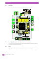
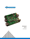
Overview
This chapter gives an overview of the hardware of EP10.
2.2
Hardware Variants
2.2.1
Keyboard Variants
EP10 has three standard variants for the keyboard layout: numeric, QWERTY and AZERTY.
Numeric Keyboard
This numeric keyboard has the number keys arranged telephone-style, with the numbers 1,2,3 along the top
row. The alphabetic characters are also arranged telephone-style, in groups of 3 or 4 [FN]-shifted characters on the number keys.
QWERTY Keyboard
This alphabetic keyboard has the alpha keys arranged in standard QWERTY layout. The number keys are accessed as [FN]-shifted characters on the left-middle side of the keyboard, and are arranged telephonic-style, with the numbers 1,2,3 along the top row (on the E, R, and T keys, respectively).
AZERTY Keyboard
This alphabetic keyboard has the alpha keys arranged in the AZERTY layout favoured by many
French-speaking parts of Europe. It is identical to the QWERTY keyboard in all respects except that the locations of the Q and W keys are interchanged with the A and Z keys, respectively.
2.2.2
Barcode Scanner/Imager Variants
EP10 comes standard with no barcode scanner/imager installed. An optional EA11 2D imager is available.
Specifications of the EA11 imager can be found in Appendix B: “EP10 Specifications”.
2.2.3
WWAN Radio Variants
The EP10 is available with one of the following Wireless WAN (WWAN) radio options:
•
Cinterion PH8 GSM/UMTS (worldwide)
•
Sierra Wireless MC5728v CDMA Sprint (US)
•
Sierra Wireless MC5728v CDMA Verizon (US)
Specifications of these radios can be found in Appendix B: “EP10 Specifications”.
Psion EP10 HDK User Manual
9
2.4
2.5
10
Psion EP10 HDK User Manual
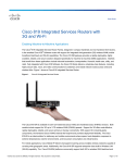
WAN 2'nd
Antenna
WAN
Antenna
GPS 2'nd
Antenna
WAN
(PH8)
(Sierra)
GPS
Star IV
GPS
Antenna
Radios
Bluetooth
Co-extistence
USB
USB
MIPI
SIM/SD
Socket
(U)SIM
Proconn
MicroSD
High
Speed
USB
PHY
UART
UART
SDIO
Display Interface
WI-FI a/b/g/n
Sensor
Display
Camera to
MIPI Converter
Camera Interface
Imager
5G
Antenna
2.4G
Antenna
Gyroscope
Light Sensor
+ Proximity
Accelerometer
+ Compass
Sensor
Sharp LCD
3.7" with
Touch panel
Display Module
SDIO
Flash
LED x 2
I2C
SPI
FLASH
RTC
Receiver
Receiver
Indicators
LED x 3
Indicators
MIC
Vibrator
Vibrator
Power Supply
And Charger
I/O
SysCon
Audio Codec
Fuel
Gauge
I2C
I2S
I2C
PCM
Speaker
Speaker
Battery
Main Board
eMMC
2GB
SDIO
CPU
AM 3715
mDDR
256MB
POP
Camera Interface
Dual MIPI
To CIF
MIPI
Camera
3Mpix
Camera Module
Side Key
Buttons
Side Key
Buttons
MIC
Keyboard
Quad Battery
Charger
Quad Dock
Desk Dock
Vehicle Cradles
AC
Wall
Adpt
AC
brick
Adpt
CLA
S Modules
(USB/RS232)
USB OTG
USB Host 2.0
Power In/Out
Docking Port
Keyboard
LED Backlight
Microphone
2.3
2D imager
EA11
Data
Capture
Chapter 2: Hardware
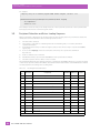
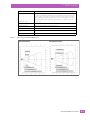
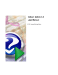
Processor
Processor
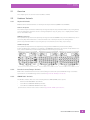
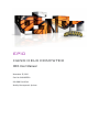
EP10 is built around a Texas Instruments AM3715 800MHz ARM Cortex-A8 processor.
Identifying Hardware
An overview of the operating system and the installed hardware on EP10 can be viewed by opening the
System applet in the Windows Control Panel.
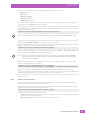
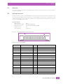
LEDs
Three LEDs are located on the upper-right side of the EP10, just above the display. When you press the
Power button, the LED flashes yellow to indicate that the EP10 has been powered up.
Chapter 2: Hardware
Power Management
Keep in mind that the application running on the EP10 can dictate how the application LED operates.
Review the documentation provided with your application to determine LED behaviour.
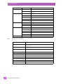
Table 2.1
Function of EP10 LEDs
LED
Function
Green/Yellow/Red Charge LED
(left-most LED)
Charge indicator, when connected to an external power supply. See the
table below for descriptions of Charge LED behaviour.
Yellow Application LED (centre LED)
Application LED. The behaviour of this LED is application dependent.
Blue Radio Power LED (right-most LED) Radio power indicator.
If the EP10 is attached to an external power supply (through a snap module or dock), the charge LED (the
left-most LED) reflects the battery charge status.
Table 2.2
EP10 Charge LED Behaviour
Charging Status
2.6
LED Colour
LED Flash Rate
Duty Cycle
No external power detected.
Not applicable
OFF
Not applicable
Battery charge complete.
GREEN
Solid ON
Continuous
Battery charging normally.
GREEN
Slow
Regular
Battery not charging because battery
temperature is outside the allowable
range: 0° C to 40° C, 32° to 104° F.
YELLOW
Normal
Regular
Battery charge failure. Unable to read
battery or non Psion battery.
RED
Solid ON
Continuous
Power Management
EP10 is powered by a lithium-ion rechargeable battery pack and can also be powered from external power.
When EP10 is powered from external power, the battery pack also charges.
Use only power sources recommended or sold by Psion for EP10.
2.6.1
Batteries
Two Lithium-Ion battery pack variants are available for the EP10: High Capacity 3600 mAh battery pack,
Model Number RV3010 and Standard Capacity 2400 mAh battery pack, Model Number RV3005. For more
details on battery safety, charging and usage, refer to the EP10 Hand-Held Computer User Manual
(P/N 8000227).
Psion EP10 HDK User Manual
11
3
SOFTWARE
SOFTWARE
3.1
3.2
3.3
3.4
3.5
3.6
3.7
3.8
Overview . . . . . . . . . . . . . . . . . . . . . . . . . .
Drivers . . . . . . . . . . . . . . . . . . . . . . . . . . .
3.2.1 Windows Drivers. . . . . . . . . . . . . . . .
3.2.2 Non-Psion Drivers . . . . . . . . . . . . . . .
System Initialization . . . . . . . . . . . . . . . . . . .
Registry Keys . . . . . . . . . . . . . . . . . . . . . . .
3.4.1 Peripheral Registry Settings. . . . . . . . .
3.4.1.1
Device Driver Registry Keys . . .
3.4.2 Software Registry Entries . . . . . . . . . .
Peripheral Detection and Driver Loading Sequence.
Serial (COM) Port Assignments. . . . . . . . . . . . .
EP10 HDK Application Development Software . . . .
3.7.1
Psion Mobile Devices SDK . . . . . . . . . .
3.7.2 EP10 HDK Development Files . . . . . . . .
3.7.3 EP10 HDK API Functions . . . . . . . . . . .
3.7.3.1
Hdk7515_Open . . . . . . . . . . .
3.7.3.2 Hdk7515_Close . . . . . . . . . . .
3.7.3.3 Hdk7515_SetPower . . . . . . . .
3.7.3.4 Hdk7515_GetPower . . . . . . . .
3.7.3.5 Hdk7515_SetPowerMode . . . . .
3.7.3.6 Hdk7515_GetPowerMode . . . . .
3.7.4 API Enumerations . . . . . . . . . . . . . . .
3.7.4.1
Hdk7515_PowerMode . . . . . . .
3.7.4.2 Hdk7515_Connector . . . . . . . .
EP10 HDK Demo Application . . . . . . . . . . . . . .
3
.
.
.
.
.
.
.
.
.
.
.
.
.
.
.
.
.
.
.
.
.
.
.
.
.
.
.
.
.
.
.
.
.
.
.
.
.
.
.
.
.
.
.
.
.
.
.
.
.
.
.
.
.
.
.
.
.
.
.
.
.
.
.
.
.
.
.
.
.
.
.
.
.
.
.
.
.
.
.
.
.
.
.
.
.
.
.
.
.
.
.
.
.
.
.
.
.
.
.
.
.
.
.
.
.
.
.
.
.
.
.
.
.
.
.
.
.
.
.
.
.
.
.
.
.
.
.
.
.
.
.
.
.
.
.
.
.
.
.
.
.
.
.
.
.
.
.
.
.
.
.
.
.
.
.
.
.
.
.
.
.
.
.
.
.
.
.
.
.
.
.
.
.
.
.
.
.
.
.
.
.
.
.
.
.
.
.
.
.
.
.
.
.
.
.
.
.
.
.
.
.
.
.
.
.
.
.
.
.
.
.
.
.
.
.
.
.
.
.
.
.
.
.
.
.
.
.
.
.
.
.
.
.
.
.
.
.
.
.
.
.
.
.
.
.
.
.
.
.
.
.
.
.
.
.
.
.
.
.
.
.
.
.
.
.
.
.
.
.
.
.
.
.
.
.
.
.
.
.
.
.
.
.
.
.
.
.
.
.
.
.
.
.
.
.
.
.
.
.
.
.
.
.
.
.
.
.
.
.
.
.
.
.
.
.
.
.
.
.
.
.
.
.
.
.
.
.
.
.
.
.
.
.
.
.
.
.
.
.
.
.
.
.
.
.
.
.
.
.
.
.
.
.
.
.
.
.
.
.
.
.
.
.
.
.
.
.
.
.
.
.
.
.
.
.
.
.
.
.
.
.
.
.
.
.
.
.
.
.
.
.
.
.
.
.
.
.
.
.
.
.
.
.
.
.
.
.
.
.
.
.
.
.
.
.
.
.
.
.
.
.
.
.
.
.
.
.
.
.
.
.
.
.
.
.
.
.
.
.
.
.
.
.
.
.
.
.
.
.
.
.
.
.
.
.
.
.
.
.
.
.
.
.
.
.
.
.
.
.
.
.
.
.
.
.
.
.
.
.
.
.
.
.
.
.
.
.
.
.
.
.
.
.
.
.
.
.
.
.
.
.
.
.
.
.
.
.
.
.
.
.
.
.
.
.
.
.
.
.
.
.
.
.
.
.
.
.
.
.
.
.
.
.
.
.
.
.
.
.
.
.
.
.
.
.
.
.
.
.
.
.
.
.
.
.
.
.
.
.
.
.
.
.
.
.
.
.
.
.
.
.
.
.
.
.
.
.
.
.
.
.
.
.
.
.
.
.
.
.
.
.
.
.
.
.
.
.
.
.
.
.
.
.
.
.
.
.
.
.
.
.
.
.
.
.
.
.
.
.
.
.
.
.
.
.
.
.
.
.
.
.
.
.
.
.
.
.
.
.
.
.
.
.
.
.
.
.
.
.
.
.
.
.
.
.
.
.
.
.
.
.
.
.
.
.
.
.
.
.
.
.
.
.
.
.
.
.
.
.
.
.
.
.
.
.
.
.
.
.
.
.
.
.
.
.
.
.
.
.
.
.
.
.
.
.
.
.
.
.
.
.
.
.
.
.
.
.
.
.
.
.
.
.
.
.
.
.
.
.
.
.
.
.
.
.
.
.
.
.
.
.
.
.
.
.
.
.
.
.
.
.
.
.
.
.
.
.
.
.
.
.
.
.
.
.
.
.
.
.
.
.
.
.
.
.
.
.
.
.
.
.
.
.
.
.
.
.
.
.
.
.
.
.
.
.
.
.
.
.
.
.
.
.
.
.
.
.
.
.
.
.
.
.
.
.
.
.
.
.
.
.
.
.
.
.
.
.
.
.
.
.
.
.
.
.
.
.
.
.
.
.
.
.
.
.
.
.
.
.
.
.
.
.
.
.
.
.
.
.
.
.
.
.
.
.
.
.
.
.
.
.
.
.
.
.
15
15
15
15
15
15
15
16
17
18
19
19
19
19
21
21
22
23
23
24
25
26
26
27
27
Psion EP10 HDK User Manual
13
Chapter 3: Software
Overview
3.1
Overview
This chapter describes the software aspects of the EP10.
3.2
Drivers
3.2.1
Windows Drivers
The Peripherals Driver
Psion provides the peripherals driver for all expansion and docking peripherals. The peripherals driver is a
stream driver activated very early in the boot sequence.
The Serial Port Driver
The full-function UART (Universal Asynchronous Receiver/Transmitter) serial port driver is loaded if required, as determined by the registry settings for any peripherals detected. For details on the registry settings, see Section 3.4.1: "Peripheral Registry Settings".
3.2.2
Non-Psion Drivers
The Psion platform loads standard device drivers. If the peripheral uses standard drivers such as serial or
USB, there is no need to load custom drivers.
There must be a registry entry for the driver and its parameters. For more information see Section 3.4:
"Registry Keys".
3.3
System Initialization
During system startup on EP10, the following sequence occurs:
1.
2.
3.
4.
The device ID is read (if a dock is connected).
The USB (OTG or Host) ports/hub are enabled.
The device-specific driver (if there is one) is loaded.
A dock notification is sent out when the shell is ready.
3.4
Registry Keys
3.4.1
Peripheral Registry Settings
This section describes the registry keys required by the peripherals driver to identify and define the behaviour of peripherals. The parent key for all of the device-specific subkeys is:
[HKLM\Drivers\BuiltIn\Peripherals\devices]
Within that key, create a subkey (if it does not already exist) for the type of connector that the peripheral
will attach to. For the EP10, only the docking connector is available, which is identified with the subkey ‘4’.
For example, the registry keys that describe peripherals connecting to the docking connector would be
stored in the subkey:
[HKLM\Drivers\BuiltIn\Peripherals\devices\4]
Within the connector type subkey create a further subkey using the Device ID reported by the peripheral.
For peripherals that attach to the docking connector, an integer value based on a resistor ID in the peripheral is used for identification (see Table 3.3: "Docking Device Identification" for resistor values). For example, the Device Name (resistor ID) for the EP10 single desktop dock is 8, therefore the correct registry key
for parameters pertaining to that peripheral is:
[HKLM\Drivers\BuiltIn\Peripherals\devices\4\8]
Device Registry Values
Within the subkey for the specific peripheral, add the following device registry values:
•
Name (REG_SZ): A descriptive name for the peripheral.
Psion EP10 HDK User Manual
15
Chapter 3: Software
Peripheral Registry Settings
•
>
PowerMode (REG_DWORD): This value determines how and when the peripheral hardware is powered
by the peripherals driver. The possible values are 1 (Auto) and 2 (Manual). If the power mode is set to
Auto, the peripheral power is managed by the peripherals driver; the peripheral is powered off when
the computer enters suspend mode and powered on when the computer resumes activity.
The default setting for this value is 2, which is the recommended setting. Under this setting, power to the peripheral
must be controlled by a loaded device driver or application.
•
Notifications (REG_DWORD): The notifications registry value determines how the user is notified
about peripherals.
This value is a bit field as defined in the following table:
Table 3.1
Bit
>
Functionality
Description
0 (LSB)
No Notification
No notification is displayed.
1 (MSB)
Notification
Enabled
Setting this flag causes a “new device” pop-up to be displayed, containing the
name and status of the peripheral. The name reported is the DeviceNameID
registry value. If that value does not exist, the Name registry value is used
instead. If that also does not exist, the Device Name from the registry key itself
is used.
The default setting for this value is 0.
•
LoadFlags (REG_DWORD): The load flags specify the functionality required by the attached peripheral,
and therefore the device driver (e.g. USB, UART, etc.) that needs to be loaded to support the peripheral. The LoadFlags value is treated as a bit field, as defined in the following table:
Table 3.2
Bit
•
•
3.4.1.1
Notifications Registry Value Definitions
LoadFlags Registry Value Definitions
Functionality
Description
0 (LSB)
Reserved
1
USB Host
2
Reserved
3
Reserved
4
USB OTG
This flag is required for docking peripherals with USB On-The-Go functionality.
5 (MSB)
Dock Power Out
The connected peripheral requires power from the battery.
This flag indicates a peripheral that requires USB Host functionality. When this bit
is set, the USB hub and ports are powered and enabled for the docking connector.
This bit must be set for any docking peripheral with a USB Host connector.
If this flag is not specified, any custom device drivers required by the peripheral must be specified in
the driver registry subkey (see Section 3.4.1.1: "Device Driver Registry Keys").
Icon (REG_DWORD): This is the Resource ID of the icon to be displayed for this peripheral in the status
bar. Currently, icons can only be loaded from Psion DLLs.
DeviceNameID (REG_DWORD): This is the Resource ID of the name string to be displayed in the “New
Device” window. Currently, the name string can only be loaded from Psion DLLs.
Device Driver Registry Keys
If the peripheral requires an additional driver to be loaded, registry keys need to be created to specify the
information for the driver. As a rule, docking peripherals do not require additional drivers, nor do many USB
peripherals. For peripherals that do require an additional driver to be loaded, follow these steps:
Within the device registry key, add a “driver” subkey. For example:
[HKLM\Drivers\BuiltIn\Peripherals\devices\4\1\driver]
16
Psion EP10 HDK User Manual
Chapter 3: Software
Software Registry Entries
Under the \driver subkey, add the following standard registry values for drivers:
•
Prefix (REG_SZ)
•
Dll (REG_SZ)
•
Index (REG_DWORD)
•
Flags (REG_DWORD)
•
IClass (REG_MULTI_SZ)
For descriptions and details of these values, consult the Microsoft documentation on developing device
drivers. Note that the Order value is not used here.
The registry keys and values in the \driver subkey are not accessed directly, but are used as a template to
create a driver entry in a different registry location. The \driver subkey and all of its entries are copied to
the following registry location:
[HKLM\Drivers\BuiltIn\Peripherals\devices\active\4\[Device ID]
Note: The driver entries are only copied if the driver key is present and contains a Dll registry value.
The drivers for detected peripherals are loaded from this “active” registry location. The driver is loaded
through a call to ActiveDeviceEx() after other initialization is finished.
It may also be necessary to copy registry keys from one location to another in the registry before loading a
driver. To do this, first create a “RegCopy” subkey. For example:
[HKLM\Drivers\BuiltIn\Peripherals\devices\4\1\RegCopy]
Within the \RegCopy subkey, add one or more entries in the form of “source” = “dest”, where source is the
source registry key and dest is the destination registry key.
Note: In the rare case that registry information needs to be copied outside HKEY_LOCAL_MACHINE,
instead name the subkey “RegCopy_HKCU” (for HKEY_CURRENT_USERS) or “RegCopy_HKCR”
(for HKEY_CLASSES_ROOT).
Remember that the backslash ‘\’ characters in the registry key strings will need to be ‘escaped’ with
another backslash character. For example:
[HKLM\Drivers\BuiltIn\Peripherals\devices\4\1\RegCopy]
“Drivers\\BuiltIn\\Peripherals\\devices\\4\\1\\RegKeys” = “Software\\Psion\\DeviceDriver”
This function copies the specified source key and all subkeys underneath it to the target location.
In rare cases, multiple drivers may need to be loaded to support a single piece of hardware. In these cases,
the Windows bus enumerator can be used (see the Microsoft documentation at
http://code.msdn.microsoft.com/BusEnum2) . Alternatively, the driver specified in the driver key can load
the other drivers.
3.4.2
Software Registry Entries
If the peripheral uses custom software, the version information for the software can be added to the
System Properties of the System Control Panel applet.
Using the registry functions, create the following registry key (where <name> is the name of the software
component as it will appear in the System Properties):
[HKLM\Software\Psion\SystemProperties\Software\<name>]
Beneath that key, set the following registry values:
•
•
@ (REG_SZ): Default value. Set to “Components” to make the software information appear in the Components list of the System Properties.
Value (REG_SZ): Enter the version of the software component here.
Psion EP10 HDK User Manual
17
Chapter 3: Software
Peripheral Detection and Driver Loading Sequence
For example:
; Registry entry for a software program named Scanner Program, version 1.5.21
;
[HKLM\Software\Psion\SystemProperties\Software\Scanner Program]
“@”=”Components”
“Value”=”1.5.21”
This example creates an entry in the Components list of the System Properties tab of the System Control
Panel applet, which reads “Scanner Program: 1.5.21”.
3.5
Peripheral Detection and Driver Loading Sequence
When a peripheral is attached to the docking connector, the following steps are performed to detect and
identify the connected hardware and load the appropriate drivers:
1.
2.
The device ID is detected.
The registry is searched for a matching device ID. If a matching entry is not found, the detect
operation terminates.
3. If a matching device entry is found, the registry entry for the driver (if any) is copied to the active
registry key.
4. If one or more RegCopy entries are found, the source keys are copied to the destination
key locations.
5. Power is enabled to the connector.
6. If USB functionality is specified, the USB (OTG or Host) ports/hub are enabled.
7. The device-specific driver (if there is one) is loaded.
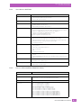
The peripheral attached to the docking connector is identified to the EP10 by means of a resistor. The value
of the resistor provides a Device ID number, and indicates which functionalities of the EP10 must be enabled
for that peripheral, according to the following table:
Table 3.3
Docking Device Identification
Device Resistor
ID
USB OTG USB Host
Power
0
1 M
Open circuit; nothing attached
1
150 K
Reserved
2
59 K
RV4002 DB9 RS-232 snap module
ON
OFF
OFF
3
34.8 K
RV4001 USB snap module
ON
OFF
OFF
ON
ON
ON
1
4
23.2 KΩ
User defined (for use with HDK)
5
16.2 K
Vehicle cradle
HDK)1
6
11.8 KΩ
User defined (for use with
7
8.66 K
Quad dock
ON
OFF
OFF
8
6.34 K
Single dock
ON
OFF
OFF
9
4.53 K
Single dock with expansion (reserved)
ON
ON
ON
10
3.01 K
Reserved
ON
ON
ON
11
1.82 K
Reserved
12
825
Reserved
13
0
Short circuit
1
18
Peripheral
These IDs are available for 3rd party peripherals, but may be used by Psion for other devices in the future.
Psion EP10 HDK User Manual
Chapter 3: Software
Serial (COM) Port Assignments
3.6
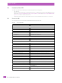
Serial (COM) Port Assignments
The default serial port assignments for the EP10 are shown in the following table. Ports not listed
are unassigned.
Table 3.4
Serial
Port
Default EP10 Serial (COM) Port Assignment
Default Assignment
Comments
COM0:
ActiveSync
ActiveSync Port - Reserved.
COM2:
GPS
This COM port is opened by applications that require GPS data.
This COM port may instead be opened by the GPS
intermediate driver.
COM5:
External USB-serial adaptor
External USB-to-serial adaptor WA4015 can be plugged into
microA/B USB port on RV4001 snap module.
COM6:
USB port replicator
RS-232 port on RV4002 snap-on module.
RS-232 port on vehicle cradle.
COM7:
Reserved.
COM9:
WWAN virtual serial port
WAN COM port.
COM18
WWAN hardware (private)
Reserved for internal use.
COM19
GPS hardware (private)
Reserved for internal use.
COM20
Bluetooth hardware (private)
Reserved for internal use.
COM24
GPS power (private)
Reserved for internal use.
Note: 1. The proper name for COM ports above COM9 is \$device\COMxx
(no “:” following the COM port number).
2. COM ports cannot be reassigned on the EP10.
3. Bluetooth creates and destroys many virtual ports.
3.7
EP10 HDK Application Development Software
To develop software applications for the EP10 and its peripherals using the Mobile Devices SDK, you must
install the following software packages on your development system. All packages are available on the
Psion Community website (http://community.psion.com), in the Downloads section (free registration is required for downloading).
3.7.1
Psion Mobile Devices SDK
The Mobile Devices SDK contains many APIs designed specifically for interacting with Psion mobile devices
and peripherals. Very simple and generic applications may not require these APIs, so it may not be necessary to install this package, but it is recommended.
This package is located in the Mobile Devices SDK subfolder of the Community website Downloads section
as “MDSDK [version] - Installer” (the current version at the time of this publication is 5.4). Download and
execute the setup program, and follow the onscreen instructions to install the package.
3.7.2
EP10 HDK Development Files
The EP10 HDK files provide an API library of C functions to interact with custom-built hardware connected
to the EP10 docking ports, as well as an HDK Demo application program.
The installation program for these files is included in the EP10 HDK package. See Section 1.6: "Obtaining the
HDK" for instructions on how to download this package to your computer.
Psion EP10 HDK User Manual
19
Chapter 3: Software
EP10 HDK Development Files
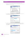
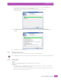
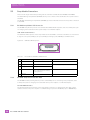
Follow these instructions to install the EP10 HDK API library and HDK Demo application files:
20
1.
Navigate to the folder with the HDK files, and double-click on the file EP10HDK_Setup.exe to begin
the installation.
The License Agreement dialog box appears:
2.
Use the scroll bar or press the Page Down key to read through the entire license agreement, then
click the I Agree button to proceed.
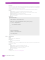
The Choose Components dialog box appears:
3.
Select the destination platform(s) you will be developing the applications for. EP10 only supports
the Microsoft Windows Embedded 6.5 operating system, but future EP10 HDK releases may have
additional options. Ensure there is a check mark in the box next to HDK for WinMobile 6.5.3 Pro,
then click Next >.
The Choose Install Location dialog box appears:
Psion EP10 HDK User Manual
Chapter 3: Software
EP10 HDK API Functions
3.7.3
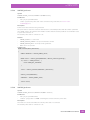
4.
To change the default installation folder, type the path into the field, or click the Browse button
and navigate to the destination folder. Click Install to proceed.
The progress dialog box appears as the installer extracts and copies the files to the
destination folders.
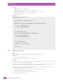
5.
If you wish to see a breakdown of the installation progress, click the Show details button.
The details window appears. Click and drag the scroll bar on the right to scroll the information up
or down.
6.
Click Close to end the installation.
EP10 HDK API Functions
The following sections describe the C functions declared in the file Hdk7515.h.
Note: HDK functions cannot be called from the xxx_Init method of a driver loaded by the peripherals driver.
3.7.3.1
Hdk7515_Open
Syntax
DWORD Hdk7515_Open( HANDLE *hdk, Hdk7515_Connector connector );
Parameters
•
•
hdk – [out] pointer to a HANDLE. If the open call succeeds, the handle is changed to a valid handle
value that can be used in other HDK operations.
connector – [in] one of the values in the Hdk7515_Connector enumeration identifying the expansion
slot (or other connector) being controlled.
Psion EP10 HDK User Manual
21
Chapter 3: Software
EP10 HDK API Functions
Description
This function is used to open a handle to the Psion HDK. The handle opened can then be used in other HDK
functions. The handle must be closed using Hdk7515_Close(). This parameter must not be null. Each handle
is tied to a single particular expansion slot or connector.
The expansion slot or other connector being controlled is determined by the 'connector' parameter.
Returns
•
ERROR_SUCCESS – if successful. The handle pointed to by 'hdk' is now valid.
•
ERROR_INVALID_PARAMETER – the 'hdk' pointer is null, or the specified connector is invalid.
•
ERROR_INVALID_DATA – an exception was generated.
•
ERROR_NOT_SUPPORTED – this peripheral is not supported by the HDK.
•
Other errors are possible.
Sample Code
DWORD OpenAndCloseHdk( )
{
HANDLE hdkHandle = INVALID_HANDLE_VALUE;
DWORD result = Hdk7515_Open(&hdkHandle, Hdk7515_Connector_Docking);
if( result != ERROR_SUCCESS ) {
return ERROR_NOT_SUPPORTED;
}
// ...
Hdk7515_Close(hdkHandle);
hdkHandle = INVALID_HANDLE_VALUE;
return ERROR_SUCCESS;
}
3.7.3.2
Hdk7515_Close
Syntax
DWORD Hdk7515_Close( HANDLE hdk );
Parameters
•
hdk – [in] a valid open HDK handle.
Description
This function is used to close an open HDK handle and release all the resources it owns. The handle cannot
be used after it is closed.
Returns
•
ERROR_SUCCESS – if successful. The handle is now closed.
•
ERROR_INVALID_HANDLE – the specified handle is invalid or null.
•
ERROR_INVALID_DATA - an exception was generated.
•
Other errors are possible.
Sample Code
See sample code for Section 3.7.3.1: "Hdk7515_Open".
22
Psion EP10 HDK User Manual
Chapter 3: Software
EP10 HDK API Functions
3.7.3.3
Hdk7515_SetPower
Syntax
DWORD Hdk7515_SetPower( HANDLE hdk, BOOL enable );
Parameters
•
•
hdk – [in] an open HDK handle.
enable – [in] the new power state of the connector being controlled (see Section 3.7.3.1:
"Hdk7515_Open").
Description
Powers on/off the connector being controlled.
The power state is reference-counted. If this function is called multiple times with the 'enable' parameter
set to TRUE, it has to be called the same number of times with the 'enable' parameter set to FALSE in order
to power the connector off.
The default power state for connectors is off.
Returns
•
ERROR_SUCCESS – if successful.
•
ERROR_INVALID_HANDLE – the specified handle is invalid.
•
ERROR_INVALID_DATA - an exception was generated.
•
Other errors are possible.
Sample Code
DWORD SetPower(BOOL powerState)
{
HANDLE hdkHandle = INVALID_HANDLE_VALUE;
DWORD result = Hdk7515_Open(&hdkHandle, Hdk7515_Connector_Docking);
if( result != ERROR_SUCCESS ) {
return ERROR_NOT_SUPPORTED;
}
result = Hdk7515_SetPower(hdkHandle, powerState);
Hdk7515_Close(hdkHandle);
hdkHandle = INVALID_HANDLE_VALUE;
return result;
}
3.7.3.4
Hdk7515_GetPower
Syntax
DWORD Hdk7515_GetPower( HANDLE hdk, BOOL *enabled );
Parameters
•
hdk – [in] an open HDK handle.
•
enabled – [out] pointer to a BOOL containing the current connector power state.
Description
This function is used to determine the current power state of a connector.
The default power state for connectors is off.
Psion EP10 HDK User Manual
23
Chapter 3: Software
EP10 HDK API Functions
Returns
•
ERROR_SUCCESS – if successful.
•
ERROR_INVALID_HANDLE – the specified handle is invalid.
•
ERROR_INVALID_PARAMETER – one of the parameters is incorrect or invalid.
•
ERROR_INVALID_DATA - an exception was generated.
•
Other errors are possible.
Sample Code
DWORD GetPower(BOOL *powerState)
{
HANDLE hdkHandle = INVALID_HANDLE_VALUE;
DWORD result = Hdk7515_Open(&hdkHandle, Hdk7515_Connector_Docking);
if( result != ERROR_SUCCESS ) {
return ERROR_NOT_SUPPORTED;
}
BOOL powerEnabled = FALSE;
result = Hdk7515_GetPower(hdkHandle, &powerEnabled);
if( result == ERROR_SUCCESS ) {
*powerState = powerEnabled;
}
Hdk7515_Close(hdkHandle);
hdkHandle = INVALID_HANDLE_VALUE;
return result;
}
3.7.3.5
Hdk7515_SetPowerMode
Syntax
DWORD Hdk7515_SetPowerMode( HANDLE hdk, Hdk7515_PowerMode mode );
Parameters
•
hdk – [in] an open HDK handle.
•
mode – [in] the new power mode for the peripheral.
Description
This function is used to configure the power mode for the peripheral attached to the connector. There are
currently two modes available: Auto and Manual.
If the power mode of the peripheral is Manual, the connector power will not be controlled by the Peripherals Driver. A loaded device driver/application must enable and disable the power.
If the power mode of the peripheral is Auto, the Peripherals driver will enable/disable power to the
connectors automatically. Power to the connector is:
1. Applied initially before the device driver for the connected hardware is loaded.
2. Removed when the hand-held is suspended.
3. Reapplied when the hand-held resumes from suspend.
The default power mode is Manual.
24
Psion EP10 HDK User Manual
Chapter 3: Software
EP10 HDK API Functions
Returns
•
ERROR_SUCCESS – if successful.
•
ERROR_INVALID_HANDLE – the specified handle is invalid.
•
ERROR_INVALID_PARAMETER – one of the parameters is incorrect or invalid.
•
ERROR_INVALID_DATA - an exception was generated.
•
Other errors are possible.
Sample Code
DWORD SetPowerMode(Hdk7515_PowerMode powerMode)
{
HANDLE hdkHandle = INVALID_HANDLE_VALUE;
DWORD result = Hdk7515_Open(&hdkHandle, Hdk7515_Connector_Docking);
if( result != ERROR_SUCCESS ) {
return ERROR_NOT_SUPPORTED;
}
Hdk7515_PowerMode mode = Hdk7515_PowerMode_Manual;
result = Hdk7515_GetPowerMode(hdkHandle, &mode);
if( result != ERROR_SUCCESS ) {
Hdk7515_Close(hdkHandle);
hdkHandle = INVALID_HANDLE_VALUE;
return result;
}
if( mode != powerMode ) {
result = Hdk7515_SetPowerMode(hdkHandle, powerMode);
}
Hdk7515_Close(hdkHandle);
hdkHandle = INVALID_HANDLE_VALUE;
return result;
}
3.7.3.6
Hdk7515_GetPowerMode
Syntax
DWORD Hdk7515_GetPowerMode( HANDLE hdk, Hdk7515_PowerMode *mode );
Parameters
•
•
hdk – [in] an open HDK handle.
mode – [out] pointer to a Hdk7515_PowerMode value that will contain the current power mode of
the connector.
Description
This function is used to retrieve the current power mode of the peripheral attached to the connector. There
are currently two modes available: Auto and Manual.
The default power mode is Manual.
Psion EP10 HDK User Manual
25
Chapter 3: Software
API Enumerations
This function can only be called by a driver, not by an application. The driver that calls this function must be
loaded by the Peripherals driver at startup.
Returns
•
ERROR_SUCCESS – if successful.
•
ERROR_INVALID_HANDLE – the specified handle is invalid.
•
ERROR_INVALID_PARAMETER – one of the parameters is incorrect or invalid.
•
ERROR_INVALID_DATA - an exception was generated.
•
Other errors are possible.
Sample Code
DWORD GetPowerMode(Hdk7515_PowerMode *powerMode)
{
HANDLE hdkHandle = INVALID_HANDLE_VALUE;
DWORD result = Hdk7515_Open(&hdkHandle, Hdk7515_Connector_Docking);
if( result != ERROR_SUCCESS ) {
return ERROR_NOT_SUPPORTED;
}
Hdk7515_PowerMode mode = Hdk7515_PowerMode_Manual;
result = Hdk7515_GetPowerMode(hdkHandle, &mode);
if( result == ERROR_SUCCESS ) {
*powerMode = mode;
}
Hdk7515_Close(hdkHandle);
hdkHandle = INVALID_HANDLE_VALUE;
return result;
}
3.7.4
API Enumerations
The following enumerations are declared in the file Hdk7515Consts.h:
3.7.4.1
Hdk7515_PowerMode
The Hdk7515_PowerMode enumeration is defined as follows:
typedef enum {
Hdk7515_PowerMode_Auto = 1,
Hdk7515_PowerMode_Manual = 2,
Hdk7515_PowerMode_Invalid = 0xffffffff
} Hdk7515_PowerMode;
26
Psion EP10 HDK User Manual
Chapter 3: Software
EP10 HDK Demo Application
3.7.4.2
Hdk7515_Connector
The Hdk7515_Connector enumeration is defined as follows:
typedef enum {
Hdk7515_Connector_Docking = 6,
Hdk7515_Connector_Invalid = 0xffffffff
} Hdk7515_Connector;
3.8
EP10 HDK Demo Application
Bundled with the EP10 HDK is a demo application that can be used to test the basic functionality of an
expansion peripheral. The files for this application (including the source code) can be located in the
..\DemoApp subfolder of where you installed the HDK files.
To run the HDK demo application, copy the 7515HDK.dll and EP10HDKDemo.exe files to the file system on
your EP10 hand-held computer. The .dll file must be located in the same folder as the executable file, or in
the system folder.
Double-tap on the executable file on the EP10 to launch the demo application. The application will run
through a sequence of function calls and report the results in status windows on the EP10 display.
•
Check power mode (Auto/Manual), and set to Manual if not already set. Report result.
•
Report current power state (enabled/disabled).
•
Toggle the power state, and report.
•
Restore the power state to original value, and report.
Tap OK to proceed through the report messages, and cycle through to the end of the application.
Psion EP10 HDK User Manual
27
4
MECHANICAL
CONSIDERATIONS
MECHANICAL CONSIDERATIONS
4.1
4.2
4.3
4.4
Overview . . . . . . . . . . . . . . . . . . . .
Materials . . . . . . . . . . . . . . . . . . . .
HDK Mechanical Files . . . . . . . . . . . .
4.3.1 3D Files . . . . . . . . . . . . . . .
4.3.2 2D Files . . . . . . . . . . . . . . .
Peripheral Design. . . . . . . . . . . . . . .
4.4.1 Physical Design Considerations .
4.4.2 USB-Serial Configuration. . . . .
4
.
.
.
.
.
.
.
.
.
.
.
.
.
.
.
.
.
.
.
.
.
.
.
.
.
.
.
.
.
.
.
.
.
.
.
.
.
.
.
.
.
.
.
.
.
.
.
.
.
.
.
.
.
.
.
.
.
.
.
.
.
.
.
.
.
.
.
.
.
.
.
.
.
.
.
.
.
.
.
.
.
.
.
.
.
.
.
.
.
.
.
.
.
.
.
.
.
.
.
.
.
.
.
.
.
.
.
.
.
.
.
.
.
.
.
.
.
.
.
.
.
.
.
.
.
.
.
.
.
.
.
.
.
.
.
.
.
.
.
.
.
.
.
.
.
.
.
.
.
.
.
.
.
.
.
.
.
.
.
.
.
.
.
.
.
.
.
.
.
.
.
.
.
.
.
.
.
.
.
.
.
.
.
.
.
.
.
.
.
.
.
.
.
.
.
.
.
.
.
.
.
.
.
.
.
.
.
.
.
.
.
.
.
.
.
.
.
.
.
.
.
.
.
.
.
.
.
.
.
.
.
.
.
.
.
.
.
.
.
.
.
.
.
.
.
.
.
.
.
.
.
.
.
.
.
.
.
.
.
.
.
.
.
.
.
.
.
.
.
.
.
.
.
.
.
.
.
.
.
.
.
.
.
.
.
.
.
.
.
.
.
.
.
.
.
.
.
.
.
.
.
.
.
.
.
.
.
.
.
.
.
.
.
.
.
.
.
.
.
.
.
.
.
.
.
.
.
.
31
31
31
31
31
31
31
32
Psion EP10 HDK User Manual
29
Chapter 4: Mechanical Considerations
Overview
4.1
Overview
This chapter describes the physical aspects of manufacturing and mounting peripherals to the base of
the EP10.
4.2
Materials
The EP10 snap-modules manufactured by Psion are manufactured using ABS + PC CX7240, and the texturing is VDI27. We recommend using a similar material for your peripherals.
4.3
HDK Mechanical Files
The Hardware Development Kit provides the following mechanical models and drawings:
4.3.1
3D Files
STEP files provide 3D models of the EP10 and snap modules for viewing with CAD software. These models
give the exact forms and dimensions of the components so that peripherals can be designed to fit the
EP10 precisely.
Table 4.1
3D Files
Description
4.3.2
Filename
3D step file of the EP10 housing
EP10.stp
3D step file of the EP10 DE9 RS-232 snap module
Serial_SnapOn.stp
3D step file of the EP10 USB snap module
USB_SnapOn.stp
2D Files
PDF files provide 2D drawings of the surfaces and attachment points of the EP10 and snap modules. The
drawings show the exact locations and relative positions of screw mountings, etc.
Table 4.2
2D Files
Description
Filename
2D pdf drawing of the EP10 front casing
EP10_Case_Front.pdf
2D pdf drawing of the EP10 rear casing
EP10_Case_Rear.pdf
2D pdf drawing of the EP10 DE9 RS-232 snap module lower casing
Serial_SnapOn_Lower.pdf
2D pdf drawing of the EP10 DE9 RS-232 snap module upper casing
Serial_SnapOn_Upper.pdf
2D pdf drawing of the left latch for an EP10 snap module
Snap_On_Latch_Left.pdf
2D pdf drawing of the right latch for an EP10 snap module
Snap_On_Latch_Right.pdf
2D pdf drawing of the EP10 USB snap module lower casing
USB_SnapOn_Lower.pdf
2D pdf drawing of the EP10 USB snap module upper casing
USB_SnapOn_Upper.pdf
4.4
Peripheral Design
4.4.1
Physical Design Considerations
Custom EP10 peripherals connect through the docking connector on the base of the unit. Whether this peripheral uses a “snap module”-type design that attaches to the unit and travels with it, or a “desktop
dock”-type design, in which the EP10 will remain at rest, there are a few important points to bear in mind
when designing your peripheral.
There are no threaded inserts for screws in the EP10 to secure the peripheral. However, there is a small
cavity on both sides of the EP10 for spring-mounted catches to latch on to. Your peripheral should include
Psion EP10 HDK User Manual
31
Chapter 4: Mechanical Considerations
USB-Serial Configuration
catches which fit in these cavities and hold the peripheral securely to the unit, but are also easily released
by the user. The EP10 HDK includes drawings and schematics of the left and right latches from the Psion
snap modules, for reference in designing these catches.
When designing your peripheral consider whether the user will need full access to the keyboard, microphone, hand-strap latch, or the battery compartment while the peripheral is attached, and make sure these
areas are not covered.
There are small alignment holes on either side of the docking connector designed to accommodate studs
on the peripheral. This helps align the electrical contacts on the peripheral precisely with the contacts of
the EP10 docking connector, and to keep them from shifting during use. it is highly recommended that the
design of your peripheral includes these alignment studs.
4.4.2
USB-Serial Configuration
The C8051 microprocessor chip used with the Psion USB-serial firmware is capable of reporting different
configurations to the Psion hand-held computer. The configuration is dependant on the voltages present on
some of the C8051 GPIO pins at initialization time. See the table below for configurations supported
by EP10.
P0.0
P0.1
P0.6
P0.7
Comments
•
1
•
•
Standard USB serial adaptor (COM5)
1
0
1
1
USB-Serial “Port 1” (COM6)
0
0
1
1
USB-Serial “Port 2” (requires additional registry keys
for support)
All other combinations reserved for Psion use.
0 = pulled low
1 = pulled high
• = high or low
The assignments are as shown to avoid conflicts when plugging in a standard USB-serial adaptor into a
vehicle cradle or desktop dock. Thus you can have two serial ports on these devices and they will not conflict with each other.
32
Psion EP10 HDK User Manual
5
CONNECTIONS
CONNECTIONS
5.1
5.2
5.3
Overview . . . . . . . . . . . . . . . . . . . . . . .
Docking Connector . . . . . . . . . . . . . . . . .
Snap Module Connectors . . . . . . . . . . . . .
5.3.1 RV4001 Snap Module USB Connector
5.3.2 RV4002 Snap Module RS-232 DB9. .
5
.
.
.
.
.
.
.
.
.
.
.
.
.
.
.
.
.
.
.
.
.
.
.
.
.
.
.
.
.
.
.
.
.
.
.
.
.
.
.
.
.
.
.
.
.
.
.
.
.
.
.
.
.
.
.
.
.
.
.
.
.
.
.
.
.
.
.
.
.
.
.
.
.
.
.
.
.
.
.
.
.
.
.
.
.
.
.
.
.
.
.
.
.
.
.
.
.
.
.
.
.
.
.
.
.
.
.
.
.
.
.
.
.
.
.
.
.
.
.
.
.
.
.
.
.
.
.
.
.
.
.
.
.
.
.
.
.
.
.
.
.
.
.
.
.
.
.
.
.
.
.
.
.
.
.
.
.
.
.
.
.
.
.
.
.
.
.
.
.
.
.
.
.
.
.
.
.
.
.
.
.
.
.
.
.
.
.
.
.
.
35
35
36
36
36
Psion EP10 HDK User Manual
33
Chapter 5: Connections
Overview
5.1
Overview
This chapter describes the details of the EP10 docking connector, and the connectors of the snap modules
available for the EP10.
5.2
Docking Connector
The 16-pin docking connector on the EP10 main logic board provides power connectivity in both directions
(to power/charge the EP10 from the peripheral, or to use the EP10 to provide power to a peripheral), as well
as USB connectivity. For serial connectivity, a USB-to-serial component must be included in the peripheral
(such as in the RV4002 snap module).
Connector Details
• Manufacturer:
• Manufacturer Part No.:
• Mating Connectors:
• Number of Pins:
• Current Rating:
Figure 5.1
Molex
Handylink 44828 SMT
Handylink 45339, 45593, 45560
16
1.0 A per pin
Diagram of EP10 Docking Connector Pins
PIN 1
PIN 16
EP10 Docking Connector Pinout
Pin
Function
I/O Type
Notes
1
Ground
Ground
2
DC power
Input
3 A maximum
3
DC power
Input
3 A maximum
4
DC power
Input
3 A maximum
5
Power out (battery)
Output
1 A maximum
6
USB Host D+
I/O
Full speed 2.0
7
USB Host D-
I/O
Full speed 2.0
8
USB OTG VBUS
Output
5 V power in (1.5 A); Power out (500 mA)
9
Dock ID
I/O
See Table 3.3: "Docking Device Identification"
10
USB OTG D-
I/O
High speed 2.0
11
USB OTG D+
I/O
High speed 2.0
12
USB OTG ID
Input
OTG ID
13
Ground
Ground
14
Reserved
N/A
Reserved
15
Reserved
N/A
Reserved
16
Ground
Ground
Psion EP10 HDK User Manual
35
Chapter 5: Connections
Snap Module Connectors
5.3
Snap Module Connectors
There are two single-unit desktop docking stations available for EP10: models RV4001 and RV4002.
The USB & Charger Snap Module (RV4001) allows you to connect a micro-USB cable and a power cable to
the EP10.
The DE9 RS-232 & Charger Snap Module (RV4002) provides an RS-232 connection and a power connection
to the EP10.
5.3.1
RV4001 Snap Module USB Connector
The RV4001 snap module provides one standard microAB USB 2.0 receptacle, and one 5 V DC power jack
for charging from a standard vehicle power adaptor or an AC wall adaptor.
USB 2.0 microAB Interface
The USB microAB receptacle on the snap module allows the EP10 to connect to a USB host or client device.
It supports low speed (1.5 Mbps), full speed (12 Mbps) and high speed (480 Mbps) communications.
Figure 5.2
USB MicroAB Receptacle
Table 5.1
Pinout Of The USB MicroAB Connector
Pin
5.3.2
Name
Description
Direction
1
VBUS
DC current from external host
Input from connected peripheral.
2
USB_D-
USB Client D-
Bidirectional (half-duplex).
3
USB_D+
USB Client D+
4
ID
ID connected plug (Only microB
plug is supported in the desktop
docking stations.)
5
Ground
RV4002 Snap Module RS-232 DB9
The RV4002 desktop docking station provides a male DB9 port for connecting serial peripherals, and a
5 V DC power jack for charging from a standard vehicle power adaptor or an AC wall adaptor.
RS-232 DB9M Interface
The 9-pin male RS-232 receptacle on the snap module connects to a stadard serial cable with a 9-pin
female connector. The port is capable of communicating at speeds from 300 kbps up to 460800 kbps.
36
Psion EP10 HDK User Manual
Chapter 5: Connections
RV4002 Snap Module RS-232 DB9
Figure 5.3
RS-232 DB9M Receptacle
Table 5.2
Pinout Of The RS-232 DB9M Connector
Pin
Name
Description
1
DCD
Data Carrier Detect
2
RXD
Received Data
3
TXD
Transmitted Data
4
DTR
Data Terminal Ready
5
GND
Ground
6
DSR
Data Set Ready
7
RTS
Request To Send
8
CTS
Clear To Send
9
RI
Ring Indicator
Psion EP10 HDK User Manual
37
A
APPENDIX: RESOURCES
AResources
Most of the following resources are available on the Psion Community website, located at
(http://community.psion.com).
Website registration is required to log in to the site and obtain the materials.
A.1
Psion User Manuals
The following user manuals are available on the Psion Community website, under Knowledge > Knowledge
Base > Product Manuals:
•
•
A.2
Psion, 2011, EP10 Hand-Held Computer (Windows Embedded 6.5) User Manual (Part number 8000227)
Psion, 2009, Mobile Devices SDK Developers Guide (Part number 8100016)
Psion Downloadable Software
The following software is available on the Psion Community website, under Downloads > Firmware/Software & Demos > Software Demos, Tools & Drivers:
•
Psion USB setup utility
The following software is available on the Psion Community website, under Downloads > Developer
(SDK/HDK):
•
•
A.3
EP10 HDK (click on Psion HDK)
Mobile Devices SDK
Psion Accessory And Parts Information
For more information on accessories and parts for the EP10, visit http://www.psion.com/products.
Psion EP10 HDK User Manual
A-1
B
APPENDIX: EP10
SPECIFICATIONS
BEP10 Specifications
B.1
B.2
B.3
B.4
B.5
EP10 Specifications – Model No. 7515 . . . . . . . . . . . . . . . . . . . . . .
B.1.1
Hardware . . . . . . . . . . . . . . . . . . . . . . . . . . . . . . . . .
B.1.2 Software . . . . . . . . . . . . . . . . . . . . . . . . . . . . . . . . .
B.1.3 Wireless Communication . . . . . . . . . . . . . . . . . . . . . . . .
B.1.4 Power Management. . . . . . . . . . . . . . . . . . . . . . . . . . .
B.1.5 Expansion Slot . . . . . . . . . . . . . . . . . . . . . . . . . . . . . .
B.1.6 Bar Code Scanner . . . . . . . . . . . . . . . . . . . . . . . . . . . .
B.1.7 Digital Camera . . . . . . . . . . . . . . . . . . . . . . . . . . . . . .
B.1.8 Voice Over IP (VOIP) . . . . . . . . . . . . . . . . . . . . . . . . . .
B.1.9 Accessories . . . . . . . . . . . . . . . . . . . . . . . . . . . . . . .
B.1.10 Approvals. . . . . . . . . . . . . . . . . . . . . . . . . . . . . . . . .
B.1.11 Environmental Specifications . . . . . . . . . . . . . . . . . . . . .
Radio Specifications . . . . . . . . . . . . . . . . . . . . . . . . . . . . . . . .
B.2.1 Murata 802.11 a/b/g/n Direct Sequence Spread Spectrum Radio
B.2.2 Murata Bluetooth Radio . . . . . . . . . . . . . . . . . . . . . . . .
B.2.3 Sierra Wireless MC5728V . . . . . . . . . . . . . . . . . . . . . . .
B.2.4 Cinterion PH8 GSM/GPRS/EDGE/UMTS Radio . . . . . . . . . . .
Lithium-Ion 2400 mAh Battery Specifications . . . . . . . . . . . . . . . . .
Lithium-Ion 3600 mAh Battery Specifications . . . . . . . . . . . . . . . . .
Internal Imager . . . . . . . . . . . . . . . . . . . . . . . . . . . . . . . . . . .
B.5.1 EA11 Decoded 2D Imager . . . . . . . . . . . . . . . . . . . . . . . .
B.5.1.1
EA11 Typical Reading Distances . . . . . . . . . . . . . .
.
.
.
.
.
.
.
.
.
.
.
.
.
.
.
.
.
.
.
.
.
.
.
.
.
.
.
.
.
.
.
.
.
.
.
.
.
.
.
.
.
.
.
.
.
.
.
.
.
.
.
.
.
.
.
.
.
.
.
.
.
.
.
.
.
.
.
.
.
.
.
.
.
.
.
.
.
.
.
.
.
.
.
.
.
.
.
.
.
.
.
.
.
.
.
.
.
.
.
.
.
.
.
.
.
.
.
.
.
.
.
.
.
.
.
.
.
.
.
.
.
.
.
.
.
.
.
.
.
.
.
.
.
.
.
.
.
.
.
.
.
.
.
.
.
.
.
.
.
.
.
.
.
.
.
.
.
.
.
.
.
.
.
.
.
.
.
.
.
.
.
.
.
.
.
.
.
.
.
.
.
.
.
.
.
.
.
.
.
.
.
.
.
.
.
.
.
.
.
.
.
.
.
.
.
.
.
.
.
.
.
.
.
.
.
.
.
.
.
.
.
.
.
.
.
.
.
.
.
.
.
.
.
.
.
.
.
.
.
.
.
.
.
.
.
.
.
.
.
.
.
.
.
.
.
.
.
.
.
.
.
.
.
.
.
.
.
.
.
.
.
.
.
.
.
.
.
.
.
.
.
.
.
.
.
.
.
.
.
.
.
.
.
.
.
.
.
.
.
.
.
.
.
.
.
.
.
.
.
.
.
.
.
.
.
.
.
.
.
.
.
.
.
.
.
.
.
.
.
.
.
.
.
.
.
.
.
.
.
.
.
.
.
.
.
.
.
.
.
.
.
.
.
.
.
.
.
.
.
.
.
.
.
.
.
.
.
.
.
.
.
.
.
.
.
.
.
.
.
.
.
.
.
.
.
.
.
.
.
.
.
.
.
.
.
.
.
.
.
.
.
.
.
.
.
.
.
.
.
.
.
.
.
.
.
.
.
.
.
.
.
.
.
.
.
.
.
.
.
.
.
.
.
.
.
.
.
.
.
.
.
.
.
.
.
.
.
.
.
.
.
.
.
.
.
.
.
.
.
.
.
.
. B-3
. B-3
. B-3
.B-4
.B-4
.B-4
.B-4
.B-4
.B-4
.B-4
.B-5
.B-5
.B-5
.B-5
.B-6
. B-7
. B-7
.B-9
B-10
B-10
B-10
.B-11
Psion EP10 HDK User Manual
B-1
Appendix B: EP10 Specifications
EP10 Specifications – Model No. 7515
B.1
EP10 Specifications – Model No. 7515
Note: Performance specifications are nominal and subject to change without notice.
B.1.1
Hardware
Physical Dimensions
•
Device: 6.2" x 3.1" x 1.2" (158 mm x 78 mm x 30.6 mm)
Weight (with battery pack)
•
Weight with 2400 mA battery: 0.8 lb (336 g)
User Interface
•
Display (Backlit)
- 3.7 in. VGA portrait mode
- Backlight feature 165 cd/m2 output
- Sunlight readable with integrated touchscreen
- Colour 480 x 640 graphic TFT
- Passive stylus or finger operation
•
Audio
- Built-in 85db mono speaker
- microphone
- receiver
•
Keyboard (Backlit)
- Numeric, QWERTY or AZERTY
- High reliability keypad ultra-white backlight
- Ergonomically enhanced for ambidextrous one-hand operation
•
Camera
- 3.2 Mega Pixel Colour
- Auto Focus
- Dual LED Flash
- Video capture capability
B.1.2
Software
Platform
•
AM3715 Processor
•
800 MHz (ARM Cortex A8)
•
On-board RAM: 256 MB SDRAM
•
On-board ROM: 2 GB Flash
Operating System
•
Microsoft Windows Embedded 6.5
Programming Environment
•
HTML, XML
•
Mobile Devices SDK
•
JavaTM
•
Visual Studio® 2008
•
Standard protocol APIs - Windows® sockets
Psion EP10 HDK User Manual
B-3
Appendix B: EP10 Specifications
Wireless Communication
Application Software
•
Internet Explorer® Mobile included with Windows® Mobile® 6
•
Wordpad
•
ActiveSync
•
Mobile Control Center (MCC) device management
B.1.3
Wireless Communication
Note: 802.11ab/g/n and Bluetooth are available simultaneously.
•
•
B.1.4
Power Management
•
•
•
•
B.1.5
Optional 3.7 V @ 2400 mAh or High Cap 3600 mAh Li-ion rechargeable batteries
Full Shift operation
SMART battery
System backup (5 minutes) during battery swap
Expansion Slot
•
B.1.6
On-board IEEE 802.11a/b/g/n
Bluetooth v2.1 radio (CCX V4 Certified
- UMTS 3.5G HSPA radio options (TBD)
- Integrated 5 band Antenna, supports both voice and data
- SiRF starIV GPS
One microSD slot
Bar Code Scanner
Note: User upgradeable.
•
B.1.7
Digital Camera
•
•
•
•
B.1.8
3.2 mega pixel colour
Auto Focus
Dual LED Flash
Video capture capability
Voice Over IP (VOIP)
•
B.1.9
2D EA11 imager
Push-to-talk
Accessories
For details about accessories available with the EP10, refer to the EP10 Hand-Held Computer User Manual.
•
•
B-4
Carrying Accessories:
- Hand strap
- Carrying case
Communications:
- Quad dock (4-site) with 10/100 BaseT Ethernet and charge functions.
- Desktop dock with Type A and Type B USB connectivity and charge functions for an internal battery
along with a spare battery.
Psion EP10 HDK User Manual
Appendix B: EP10 Specifications
Approvals
•
•
B.1.10
Approvals
•
•
•
•
•
B.1.11
Power supplies:
- AC wall adaptor
- Vehicle power outlet adaptor
- Quad charger (4-site)
- Snap Module: USB DE9M powered serial plus Charger
- Snap Module: USB Host/Client plus Power/Charger
Vehicle peripherals:
- Powered and Non-powered cradle
- RAM Mount with screws
FCC Parts 15B, 15C, 15E, 22H, 24E, 27
IC RSS-210, RSS-132, RSS-133
EN 300 328, EN 301 489, EN 55022, EN55024, EN301 511, EN301 908, EN300 440, EN301 893
Safety IEC/EN 60950-1
Laser Safety IEC 60825-1
Environmental Specifications
•
•
•
•
•
•
•
Operating Temperature: 14ºF to 122 ºFC (-10ºC to +50ºC)
Storage Temperature: -4ºF to 140ºF (-20ºC to +65ºC)
Relative Humidity: 5% to 95% RH non-condensing
Rain & Dust Protection: IP54, IEC 529
Drop: 5 ft (1.5 m) - 26 drops to polished concrete
Tumble: 250 times at 0.5 m
ESD: +/- 15k VDC air discharge, +/- 8k VDC contacts
B.2
Radio Specifications
B.2.1
Murata 802.11 a/b/g/n Direct Sequence Spread Spectrum Radio
Parameter
Sub-parameters
Form Factor
Antenna Port
Antenna Type
Antenna Gain
Transmit Power
Specifications
Embedded surface mount module, 11.4 x 9.4 mm
* This is a combo module containing both Wi-Fi
802.11a/b/g/n and Bluetooth V2.1+EDR radio
802.11b/g/n
U.FL jack. Non-diversity.
Multiplexed between 802.11b/g/n (2.4GHz) and
Bluetooth radio
802.11a/n
U.FL jack. Non-diversity.
802.11b/g/n
PIFA antenna. Covers 2400-2484 MHz
@ <2.0:1 VSWR
802.11a/n
PIFA antenna. Covers 5150-5860 MHz
@ <2.0:1 VSWR
802.11b/g/n
3.73 dBi
802.11a/n
4.85 dBi
802.11b
+18 dBm typical
802.11g
+13 dBm typical
802.11a
+12 dBm typical
802.11n (2.4 GHz)
+12 dBm typical
802.11n (5 GHz)
+12 dBm typical
Psion EP10 HDK User Manual
B-5
Appendix B: EP10 Specifications
Murata Bluetooth Radio
Parameter
Frequency Range
RX Sensitivity
Data Rates
EVM
Sub-parameters
802.11b/g/n
2400-2484 MHz
802.11a/n
5150-5350 MHz, 5480-5720 MHz and 57255845 MHz
802.11b
-78 dBm @ 11 Mbps
802.11g
-67 dBm @ 54 Mbps
802.11a
-67 dBm @ 54 Mbps
802.11n (2.4 GHz)
-66 dBm @ 65 Mbps
802.11n (5 GHz
-66 dBm @ 65 Mbps
802.11b
1,2,5.5,11 Mbps
802.11a/g
6,9,12,18,24,36,48,54 Mbps
802.11n
6.5,13,19.5,26,39,52,58.5,65 Mbps
802.11b
32% max
802.11g
-26 dB max
802.11a
-26 dB max
802.11n (2.4 GHz)
-29 dB max
802.11n (5 GHz
-29 dB max
Bluetooth Coexistence
B.2.2
Specifications
TI Wilink6 proprietary WiFi-BT co-existent scheme.
Murata Bluetooth Radio
Parameter
B-6
Specifications
Form Factor
Embedded surface mount module, 11.4 x 9.4 mm
* This is a combo module containing both Wi-Fi 802.11a/b/g/n and Bluetooth
V2.1+EDR radio
Antenna Port
U.FL jack (shared with Wi-Fi 802.11b/g/n radio)
Antenna Type
PIFA antenna. Covers 2400-2484 MHz
@ <2.0:1 VSWR
Antenna Gain
3.73 dBi
Transmit Power
6.5 dBm typical
Frequency Range
2.400-2.4835 GHz
Channel
79
RX Sensitivity
-90 dBm typical, -70 dBm max
Data Rates
-90 dBm typical, -70 dBm max
802.11 Coexistence
TI Wilink6 proprietary WiFi-BT co-existent scheme.
Psion EP10 HDK User Manual
Appendix B: EP10 Specifications
Sierra Wireless MC5728V
B.2.3
Sierra Wireless MC5728V
Features
Specifications
Physical
• Small PCI-Express Mini Card standards-based form factor. Adheres to Rev 1.2
of the PCI Express Mini Card Specification
• Two U.FL RF connector jacks
Electrical
The MC5728V Mini Card is self-shielded; no additional shielding is required.
Environmental
Temperature operating range:
• IS-98D compliance: -30 to +60° C
• Reduced RF performance: +60 to +75° C
RF
• Dual-band support for both the 800 MHz cellular and 1.9 GHz PCS bands
• Receive diversity support for the 800 MHz cellular and 1.9 GHz PCS bands
• Adheres to CDMA authentication as specified in CDMA 1X
• Support for IS-95A/B and CDMA 1X Release 0/A
• Support for IS-856 1xEV-DO Revision A
Support for gpsOne™ and stand-alone GPS
Application Interface
• USB supporting multiple logical channels over the USB MUX protocol
• USB selective suspend supported for maximum power savings
• Wakeup Enable-the modem can be set to wake the host device upon ring,
restoration of radio coverage, and/or receipt of SMS
• AT command interface
Voice
The MC5728V Mini Card has internal IS-127 and IS-733 vocoders and supports:
• Call origination
• Silent retry call origination protocol
• Echo cancellation
• E911
• Incoming call notification
Packet Mode
• IS-2000 data rates up to 1531 kbps, simultaneous forward and reverse
channel
• IS-856 (1xEV-DO Rev. A) data rates up to 3.1 Mbps forward channel and 1.8
Mbps reverse channel
IS-95 circuit-switched
• V.34 data rates to 14.4 kbps
• Quick Net Connect (QNC) support
Short Message Service (SMS) • Send and receive
• Notification of new messages
B.2.4
Cinterion PH8 GSM/GPRS/EDGE/UMTS Radio
Feature
Specifications
General
Frequency bands
GSM/GPRS/EDGE: Quad band, 850/900/1800/1900MHz
UMTS/HSPA+: Five band, 800/850/AWS/1900/2100MHz
GSM class
Small MS
Output power (according to
Release 99)
Class 4 (+33dBm ±2dB) for EGSM850
Class 4 (+33dBm ±2dB) for EGSM900
Class 1 (+30dBm ±2dB) for GSM1800
Class 1 (+30dBm ±2dB) for GSM1900
Class E2 (+27dBm ± 3dB) for GSM 850 8-PSK
Class E2 (+27dBm ± 3dB) for GSM 900 8-PSK
Class E2 (+26dBm +3 /-4dB) for GSM 1800 8-PSK
Class E2 (+26dBm +3 /-4dB) for GSM 1900 8-PSK
Class 3 (+24dBm +1/-3dB) for UMTS 2100, WCDMA FDD Bd I
Class 3 (+24dBm +1/-3dB) for UMTS 1900,WCDMA FDD Bd II
Class 3 (+24dBm +1/-3dB) for UMTS AWS, WCDMA FDD Bd IV
Class 3 (+24dBm +1/-3dB) for UMTS 850, WCDMA FDD Bd V
Class 3 (+24dBm +1/-3dB) for UMTS 800, WCDMA FDD Bd VI
Psion EP10 HDK User Manual
B-7
Appendix B: EP10 Specifications
Cinterion PH8 GSM/GPRS/EDGE/UMTS Radio
Feature
Specifications
Operating Temperature (board
temperature)
Normal operation: -30°C to +85°C
Restricted operation: -40°C to +95°C
Physical
Dimensions: 33.9mm x 50mm x 3.1mm
Weight: approx. 9.5g
RoHS
All hardware components fully compliant with EU RoHS Directive
HSPA features
3GPP Release 6, 7
DL 14.4Mbps, UL 5.7Mbps
UE CAT. [1-6], 11, 12 supported
Compressed mode (CM) supported according to 3GPP TS25.212
UMTS features
3GPP Release 4
PS data rate - 384 kbps DL / 384 kbps UL
CS data rate - 64 kbps DL / 64 kbps UL
GSM/GPRS/EGPRS features
Data transfer
GPRS:
• Multislot Class 12
• Full PBCCH support
• Mobile Station Class B
• Coding Scheme 1 - 4
EGPRS:
• Multislot Class 12
• EDGE E2 power class for 8 PSK
• Downlink coding schemes - CS 1-4, MCS 1-9
• Uplink coding schemes - CS 1-4, MCS 1-9
• SRB loopback and test mode B
• 8-bit, 11-bit RACH
• PBCCH support
• 1 phase/2 phase access procedures
• Link adaptation and IR
• NACC, extended UL TBF
• Mobile Station Class B
CSD:
• V.110, RLP, non-transparent
• 14.4kbps
• USSD
SMS
Point-to-point MT and MO
Cell broadcast
GPS features
Protocol
NMEA
Modes
Standalone GPS, Assisted GPS (control plane AGPS, E911 / user plane AGPS,
gpsOneXTRA™)
General
Power saving modes
GPS tracking in parallel to 2G/3G diversity operation
Software
AT commands
Hayes, 3GPP TS 27.007 and 27.005, and proprietary Cinterion Wireless
Modules commands
SIM application toolkit
SAT Release 99
Audio
Audio speech codecs
GSM: AMR, EFR, FR, HR
3GPP: AMR
Speakerphone operation, echo cancellation, noise suppression
Firmware update
Generic update from host application over ASC0 or USB
Interfaces
B-8
Module interface
80-pin board-to-board connector
Antenna
50Ohms. Main GSM/UMTS antenna, UMTS diversity antenna, GPS antenna
(active/passive)
Psion EP10 HDK User Manual
Appendix B: EP10 Specifications
Lithium-Ion 2400 mAh Battery Specifications
Feature
Specifications
USB
USB 2.0 High Speed (480Mbit/s) device interface
Serial interface
ASC0:
• 8-wire modem interface with status and control lines,
unbalanced, asynchronous
• Adjustable baud rates from 9,600bps up to 921,600bps
• Supports RTS0/CTS0 hardware flow control
• Multiplex ability according to GSM 07.10 Multiplexer Protocol
UICC interface
Supported chip cards: UICC/SIM/USIM 3V, 1.8V
Special features
B.3
Phonebook
SIM and phone
Antenna
SAIC (Single Antenna Interference Cancellation) / DARP (Downlink
Advanced Receiver Performance)
RX diversity type 3i
Lithium-Ion 2400 mAh Battery Specifications
Description
Specification
Model Number
RV3005
Part Number
1100911-000
Chemistry
Lithium-Ion (Li-Ion)
Battery Voltage
2.7 V ~ 4.2 V (minimum ~ maximum)
3.7 V (nominal)
Capacity
2300 mAh/8.5 Whr (typical)
2400 mAh/8.8 Whr (minimum)
Charge Current
1.15 A (typical)
Charge Voltage
4.2V +/- 0.05
Charge Method
Constant-current/constant-voltage (CC/CV)
Discharge Current
1.15 A (typical)
2.8 A (maximum)
Internal Resistance
135 m (typical)
Storage Temperature
-20°C to +60°C (-4°F to +140°F)
Charge temperature
0°C to +45°C (32°F to +113°F) (typical)
Discharge Temperature
-20°C to +60°C (-4°F to +140°F) (typical)
Charge Taper Current
48 ~ 120 mA
Charge Time
3 hrs. (typical)
Pre-condition Charge
Current
200 ~ 240 mA
Pre-condition Charge Termination Voltage
3V
Cycle Life
300 charge/discharge cycles with no degradation below 80% of nominal capacity
based on 0.5 C charge / 0.5 C discharge rates (to 3.0 V) @ 23° C.
Psion EP10 HDK User Manual
B-9
Appendix B: EP10 Specifications
Lithium-Ion 3600 mAh Battery Specifications
B.4
Lithium-Ion 3600 mAh Battery Specifications
Description
Specification
Model Number
RV3010
Part Number
1100912-000
Chemistry
Lithium-Ion (Li-Ion)
Battery Voltage
2.7 V ~ 4.2 V (minimum ~ maximum)
3.7 V (nominal)
Capacity
3600 mAh/13.32Whr (typical)
3450 mAh/12.76 Whr (minimum)
Charge Current
1.72 A (typical)
Charge Voltage
4.2V +/- 0.05
Charge Method
Constant-current/constant-voltage (CC/CV)
Discharge Current
1.72 A (typical)
2.8 A (maximum)
B.5
Internal Resistance
125 m (typical)
Storage Temperature
-20°C to +60°C (-4°F to +140°F)
Charge temperature
0°C to +45°C (32°F to +113°F) (typical)
Discharge Temperature
-20°C to +60°C (-4°F to +140°F) (typical)
Charge Taper Current
48 ~ 120 mA
Charge Time
3 hrs. (typical)
Pre-condition Charge
Current
300 ~ 360 mA
Pre-condition Charge Termination Voltage
3V
Cycle Life
300 charge/discharge cycles with no degradation below 80% of nominal capacity
based on 0.5 C charge / 0.5 C discharge rates (to 3.0 V) @ 23° C.
Internal Imager
This section lists specifications for the EA11 Decoded 2D imager.
B.5.1
EA11 Decoded 2D Imager
Parameter
Specification
Scan Rate
2D mode: 56 images/s auto adaptive
Linear Emulation Mode
200 scans/s auto adaptive
Scan Angle
38.9° (horizontal), 25.4° (vertical)
Optical Resolution
752 (H) x 480 (V) pixels, 256 gray levels
Print Contrast
Down to 25%
Versions
Standard range and high density
B-10 Psion EP10 HDK User Manual
Appendix B: EP10 Specifications
EA11 Decoded 2D Imager
Parameter
Symbologies - 1D
B.5.1.1
Specification
EAN/UPC, GS1 Databar (limited expanded & omni-directional), RSS, Code 39,
Code 128, UCC/EAN 128, ISBN, ISBT, Interleaved/Matrix/ Industrial and Standard
2 of 5, Codabar, Code 93/93i, Code 11, MSI, Plessey, Telepen, postal codes (Australian Post, BPO, Canada Post, Dutch Post, Japan Post, PostNet, Sweden Post)
Symbologies - 2D
Data Matrix, PDF417, Micro PDF 417, Codablock Maxicode, QR, Aztec GS1 composite codes
Voltage (optics)
3.3V -5% / +10% (typical values)
Operating Current
170mA - 310mA (lighting condition dependent)
Power Saving Mode
2mA
Ambient Light
Works in any lighting conditions, from 0 to 100,000 lux
Regulatory Approvals
UL, VDE certified, RoHS compliant
EA11 Typical Reading Distances
Psion EP10 HDK User Manual
B-11
C
APPENDIX: HDK LICENSE
AGREEMENT
CHDK License Agreement
C.1
C.2
C.3
C.4
C.5
C.6
C.7
C.8
C.9
C.10
HARDWARE DEVELOPER KIT LICENSE AGREEMENT. . . . . .
GRANT OF LICENSE . . . . . . . . . . . . . . . . . . . . . . . . .
REQUIREMENTS, RESTRICTIONS, RIGHTS AND LIMITATIONS .
HIGH RISK ACTIVITIES . . . . . . . . . . . . . . . . . . . . . . . .
DISCLAIMER OF WARRANTY . . . . . . . . . . . . . . . . . . . .
LIMITATION OF LIABILITY . . . . . . . . . . . . . . . . . . . . . .
COPYRIGHTS, OWNERSHIP AND PROPRIETARY RIGHTS . . .
CONFIDENTIALITY . . . . . . . . . . . . . . . . . . . . . . . . . .
ENDING THIS AGREEMENT . . . . . . . . . . . . . . . . . . . . .
GENERAL . . . . . . . . . . . . . . . . . . . . . . . . . . . . . . .
.
.
.
.
.
.
.
.
.
.
.
.
.
.
.
.
.
.
.
.
.
.
.
.
.
.
.
.
.
.
.
.
.
.
.
.
.
.
.
.
.
.
.
.
.
.
.
.
.
.
.
.
.
.
.
.
.
.
.
.
.
.
.
.
.
.
.
.
.
.
.
.
.
.
.
.
.
.
.
.
.
.
.
.
.
.
.
.
.
.
.
.
.
.
.
.
.
.
.
.
.
.
.
.
.
.
.
.
.
.
.
.
.
.
.
.
.
.
.
.
.
.
.
.
.
.
.
.
.
.
.
.
.
.
.
.
.
.
.
.
.
.
.
.
.
.
.
.
.
.
.
.
.
.
.
.
.
.
.
.
.
.
.
.
.
.
.
.
.
.
.
.
.
.
.
.
.
.
.
.
.
.
.
.
.
.
.
.
.
.
.
.
.
.
.
.
.
.
.
.
.
.
.
.
.
.
.
.
.
.
.
.
.
.
.
.
.
.
.
.
.
.
.
.
.
.
.
.
.
.
.
.
.
.
.
.
.
.
.
.
.
.
.
.
.
.
.
.
.
.
.
.
.
.
.
.
.
.
.
.
.
.
.
.
.
.
.
.
.
.
.
.
.
.
.
.
.
.
.
.
. C-3
. C-3
. C-3
. C-3
.C-4
.C-4
.C-4
.C-4
.C-4
.C-4
Psion EP10 HDK User Manual
C-1
Appendix C: HDK License Agreement
HARDWARE DEVELOPER KIT LICENSE AGREEMENT
C.1
HARDWARE DEVELOPER KIT LICENSE AGREEMENT
IMPORTANT - READ CAREFULLY:
This Hardware Developer Kit License Agreement (“Agreement”) is a legal agreement between you and
Psion (“we”), the licensor of Psion Hardware Developer Kit (“HDK”) which is downloaded from the Psion
website, for developers of hardware expansion modules intended to be used with the Psion hand-held
mobile devices.
By clicking on the “Accept” or other appropriate assent button and/or installing the HDK, you agree to be
and are hereby bound by the terms and conditions of this Agreement. If you do not agree with this Agreement, we do not grant you a license to the HDK, and you may not install or use the HDK or any accompanying documentation.
The HDK is the property of Psion Inc. or its licensors and is protected by copyright laws and international
copyright treaties, as well as other intellectual property laws and treaties. The HDK is licensed, not sold.
Psion Inc. provides the HDK and licenses its use worldwide. You assume responsibility for the selection of
the HDK to achieve your intended results, and for the use and results obtained from it.
C.2
GRANT OF LICENSE
We hereby grant you and you hereby accept a non-exclusive, non-transferable, royalty-free license to use
the HDK to develop hardware expansion modules to be used with the Psion hand-held mobile devices
subject to the terms and restrictions set forth in this Agreement. Except as explicitly set forth below, (i) you
are not permitted to sell, lease or rent, distribute or sublicense the HDK or to use the HDK in a time-sharing
arrangement or in any other unauthorized manner; (ii) no license is granted to you in the human readable
code of the HDK (source code); and (iii) this Agreement does not grant you any rights to patents, copyrights, trade secrets, trademarks, intellectual property or any other ownership rights with respect to
the HDK.
The HDK is licensed to be used on any personal computer and/or Psion hand-held mobile devices, provided
that the HDK is used only in connection with your development of hardware expansion modules for use and
compatible with the Psion hand-held mobile devices (the “Expansion(s)”). The HDK contains certain documentation, drawings, programs, files, specifications, datasheets and APIs. You may distribute the HDK in
object code format solely as part of your Expansion. The HDK shall be distributed to your customers under
the terms of your standard end user license agreement, provided it includes terms that are substantially
similar to those described herein. You are required to include Psion’s copyright notices on your Expansion
that includes the HDK.
C.3
REQUIREMENTS, RESTRICTIONS, RIGHTS AND LIMITATIONS
a.Distribution. Except as provided for in this Agreement, you may not distribute the HDK, in whole or in
part, to any other third party.
b.Virus Program. You may not develop or knowingly incorporate any virus program that may be harmful to
a computer or a network in conjunction with the HDK, or use the HDK for any other purpose as which may
be harmful to a third party.
c.Assignment. You may not assign or transfer the HDK to a third party or allow a third party to use
the same.
d.Reverse Engineering. Modification, reverse engineering, reverse compiling, or disassembly of the HDK is
expressly prohibited.
e.Export Restrictions. You agree that you will not export or re-export the HDK, or any part or copies thereof,
or any products utilizing the HDK in violation of applicable laws or regulations of the United States or the
country in which you obtained them.
f.Approvals. You agree that it is your responsibility to obtain any required regulatory approvals required for
the sale of products utilizing the HDK anywhere such products are offered for sale.
C.4
HIGH RISK ACTIVITIES
The HDK is not fault-tolerant and is not designed, manufactured or intended for use or resale as on-line
control equipment in hazardous environments requiring fail-safe performance, such as in the operation of
nuclear facilities, aircraft navigation or communication systems, air traffic control, direct life support machines, or weapons systems, in which the failure of the HDK could lead to death, personal injury, or severe
Psion EP10 HDK User Manual
C-3
Appendix C: HDK License Agreement
DISCLAIMER OF WARRANTY
physical or environmental damage (“High Risk Activities”). We specifically disclaim any express or implied
warranty of fitness for High Risk Activities.
C.5
DISCLAIMER OF WARRANTY
We do not warrant uninterrupted or error free operation of the HDK nor do we warrant that the HDK will
meet your requirements. THE HDK AND DOCUMENTATION ARE PROVIDED “AS-IS” WITHOUT ANY WARRANTY WHATSOEVER AND WITHOUT ANY TECHNICAL SUPPORT OF ANY KIND. WE DISCLAIM ANY AND
ALL REPRESENTATIONS, WARRANTIES AND CONDITIONS, WHETHER EXPRESS OR IMPLIED, INCLUDING,
BUT NOT LIMITED TO, THE IMPLIED WARRANTIES OR CONDITIONS OF MERCHANTABLE QUALITY OR
FITNESS FOR A PARTICULAR PURPOSE. WE DO NOT WARRANT OR MAKE ANY REPRESENTATIONS REGARDING THE USE OR THE RESULTS OF THE USE OF THE HDK IN TERMS OF ITS CORRECTNESS, ACCURACY, RELIABILITY, USE WITH FUTURE PSION DEVICES INTRODUCED, OR OTHERWISE. YOU EXPRESSLY
ACKNOWLEDGE AND AGREE THAT USE AND MODIFICATION OF THE HDK IS AT YOUR SOLE RISK AND
YOU ARE RESPONSIBLE FOR INSTALLATION AND MODIFICATION OF THE HDK ON YOUR COMPUTER.
C.6
LIMITATION OF LIABILITY
Under no circumstances are we or our third party suppliers liable for damages of third parties claimed
against you, or for harm to your records or data, or special, incidental, indirect, or consequential damages,
including but not limited to lost profits, lost business revenue or failure to realize expected savings, loss of
data, loss of use of the HDK or any associated equipment, downtime and user's time, even if you informed
us of their possibility, or for breach of any express or implied warranty, breach of contract, negligence, strict
liability or any other legal theory related to the HDK. This limitation applies whether you are entitled to
claim damages from us or our third party suppliers as a matter of contract or tort.
C.7
COPYRIGHTS, OWNERSHIP AND PROPRIETARY RIGHTS
All title and copyrights in and to the HDK, and any copies thereof, are owned by Psion Inc. or its suppliers.
The HDK also contains copyrighted material licensed from our suppliers and all rights to such copyrighted
material rests with such suppliers. We retain title to the HDK and any copies made from it. Any copies of the
HDK you made are subject to the restrictions of this Agreement.
WE DISCLAIM ALL WARRANTIES AND INDEMNITIES, EXPRESS, IMPLIED OR STATUTORY, FOR PATENT OR
COPYRIGHT INFRINGEMENT.
C.8
CONFIDENTIALITY
You agree not to use or disclose any proprietary information provided by us, except for the purposes of this
Agreement. You agree not to reproduce any of the copyrighted materials unless expressly permitted by
this Agreement.
C.9
ENDING THIS AGREEMENT
We may terminate this Agreement and your license immediately without notice if (a) you fail to comply with
any term of this Agreement, or (b) your rights are assigned by you, by operation of law or otherwise. In such
event, you must return or destroy all copies and component parts of the HDK and documentation, as well as
any other Psion proprietary information in your possession, within fourteen (14) days of the date of termination. Any rights and obligations under this Agreement that by their nature continue after it ends, will
remain in effect until they are completed.
C.10
GENERAL
The laws of the Province of Ontario and the federal laws applicable therein, excluding the conflict of laws
provisions, govern this Agreement. If any provision of this Agreement is deemed invalid or unenforceable
by any country, that particular provision will be deemed modified to the extent necessary to make the provision valid and enforceable, and the remaining provisions will remain in full force and effect. Failure by us
to insist on strict performance or to exercise a right when entitled, does not prevent us from doing so at a
later time, either in relation to that default or any subsequent one.
No modifications of this Agreement shall be effective unless in writing and approved by us.
C-4
Psion EP10 HDK User Manual
Appendix C: HDK License Agreement
GENERAL
You acknowledge that you have read this Agreement, understand it, and that it is the complete agreement
between you and Psion with respect to the subject matter hereof and supersedes all prior agreements, oral
or written.
C-5
Psion EP10 HDK User Manual
INDEX
INDEXSYMBOLS
keyboard 9
radio 9
scanner/imager 9
Symbols
@ (registry value) 17
Numbers
802.11a/b/g/n radio specifications B-5
802.11ab/g/n radio B-5
A
API 21–27
enumerations 26–27
functions 21–26
B
bar code reader
applications B-10
internal or integrated B-10
battery 11
battery specifications B-9, B-10
block diagram 10
Bluetooth specs B-6
C
C8051 microprocessor 32
CDMA radio 9
COM ports 19
conventions, text 3
D
demo application 27
development platform 3
development software 19
device
drivers 16
device driver registry keys 16
DeviceNameID (registry value) 16
digital camera specifications B-4
Dll (registry value) 17
docking connector
pinout 35
drivers 15
device 16
non-Psion 15
peripherals 15
serial port 15
Windows 15
DSSS, 802.11a/b/g/n radio B-5
E
EA11 2D Imager specifications B-10
EP10
about 5
accessories A-1
battery 11
block diagram 10
identifying hardware 10
loading sequence 18
operating system 5
power management 11
processor 10
registry keys 15–17
specifications B-3
system initialization 15
variants 9
F
files 4
2D 31
3D 31
Flags (registry value) 17
G
GSM/GPRS/EDGE radio specifications B-7
H
HDK
about 3
contents 4
development files 19
development platform 3
downloading 5
files 4
licence agreement C-3
mechanical files 31
obtaining 5
software A-1
I
IClass (registry value) 17
Icon (registry value) 16
Index (registry value) 17
indicators
LED functions 10
initialization sequence (EP10) 15
interface, user B-3
L
LED
functions 10
license agreement C-3
LoadFlags (registry value) 16
M
material 31
Mobile Devices SDK, Psion 19
module
material 31
N
Name (registry value) 15
Notifications (registry value) 16
O
Order (registry value) 17
P
peripheral
design, physical considerations 31
detection 18
peripheral design 31
peripheral registry keys 15–16
peripherals driver 15
PH8 GSM/GPRS/EDGE radio specifications B-7
PH8 radio 9
Psion EP10 HDK User Manual
I
Index
pinout
docking connector 35
RS-232 connector (RV4002 snap module) 37
USB connector (RV4001 snap module) 36
ports
internal scanner B-10
power management 11
power management specifications B-4
PowerMode (registry value) 16
Prefix (registry value) 17
R
radio
802.11a/b/g /n Direct Sequence SS B-5
802.11ab/g/n radio specifications B-5
Bluetooth specs B-6
Cinterion PH8 GSM/GPRS/EDGE radio specifications
B-7
radio specifications B-5
registry keys 15–17
return-to-factory warranty 3
RS-232
connector (RV4002 snap module)
pinout 37
DB9M interface (RV4002 snap module) 36
snap module (RV4002) 36
S
scanner
bar code applications B-10
EA11 2D Imager specifications B-10
integrated B-10
specifications, internal B-10
serial 32
serial port driver 15
serial ports 19
snap modules 36–37
RV4001 (USB) 36
RV4002 (RS-232) 36
software specifications B-3
specifications
802.11b/g B-5
bar code application B-4
digital camera B-4
for EP10 hand-held B-3
physical dimensions B-3
power management B-4
scanner, internal B-10
software platform B-3
user interface B-3
wireless communication B-4
T
text conventions 3
U
USB
microAB interface (RV4001 snap module) 36
snap module (RV4001) 36
USB connector (RV4001 snap module)
pinout 36
USB-serial configuration 32
V
Value (registry value) 17
W
warranty 3
wireless communication specifications B-4
II
Psion EP10 HDK User Manual