1
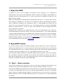
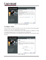
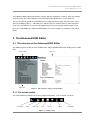
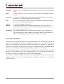
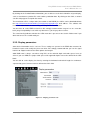
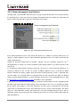
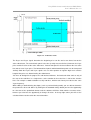
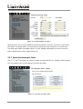
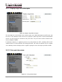
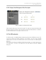
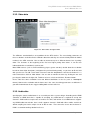
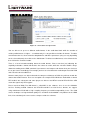
Easy EDID Creator
Advanced EDID Editor
User's Manual
Table of contents
1.
ABOUT THE EDID.......................................................................................................................... 3
2.
EASY EDID CREATOR .................................................................................................................. 3
2.1. STEP 1 – SELECT RESOLUTION ........................................................................................................ 3
2.2. STEP 2 – DVI OR HDMI .................................................................................................................. 5
2.3. STEP 3 – SELECT AUDIO.................................................................................................................. 5
2.4. STEP 4 – FINISH ............................................................................................................................. 6
3.
THE ADVANCED EDID EDITOR ................................................................................................... 7
3.1. THE STRUCTURE OF THE ADVANCED EDID EDITOR .......................................................................... 7
3.1.1. The action toolbar ................................................................................................................. 7
3.1.2. The main menu ..................................................................................................................... 8
3.1.3. The map window ................................................................................................................. 10
3.2. THE FIRST 128 BYTES ................................................................................................................... 10
3.2.1. Vendor/Product information ................................................................................................ 10
3.2.2. Display parameters ............................................................................................................. 11
3.3.3. Power management and features ....................................................................................... 12
3.3.4. Gamma/Color and Established timings .............................................................................. 13
3.3.5. Standard timings ................................................................................................................. 13
3.3.6. Preferred timing mode ........................................................................................................ 14
3.3.7. About the descriptor fields .................................................................................................. 16
3.3.8. Product serial number descriptor ........................................................................................ 17
3.3.9. Alphanumeric string descriptor ........................................................................................... 17
3.3.10. Product name descriptor ................................................................................................... 17
3.3.11. Display range limits descriptor .......................................................................................... 18
3.3.12. Color point descriptor ........................................................................................................ 18
3.3.13. Standard timing identifier definition descriptor .................................................................. 19
3.3.14. CVT 3 Byte Code Descriptor ............................................................................................ 19
3.3.15. Established timings III descriptor ...................................................................................... 20
3.3.16. Display Color Management Data Descriptor .................................................................... 21
3.3 THE CEA EXTENSION ..................................................................................................................... 21
3.3.1. General CEA settings ......................................................................................................... 22
3.3.2. Video data ........................................................................................................................... 23
3.3.3. Audio data ........................................................................................................................... 23
3.3.4. Speaker allocation .............................................................................................................. 25
3.3.5. HDMI ................................................................................................................................... 25
Page 2 / 27
Easy EDID Creator and Advanced EDID Editor
User’s Manual Rev. 1.0
1. About the EDID
The EDID can cause a lot of headaches for beginner system integrators, so it’s important to
understand the main aspects of the EDID data structure. However the Lightware factory EDIDs are
designed to cover the most practical cases, in some circumstances the editing or creation of a new
EDID cannot be avoided.
EDID is the abbreviation of Extended Display Identification Data and it is a 128 byte data structure
which defines the capabilities of a sink device. If the support for a format is not indicated in the display
device’s EDID then according to the standard the source is strictly forbidden to send this type of
signal. This is very convenient for the home users – this behavior guarantees the best interoperability
between the different devices – but it can make a lot of trouble for system integrators with more
sources and sinks at same time.
Unfortunately the standard is very complicated and it’s not easy to understand the cross references
and relations between the different versions even for the experienced users. This chapter will provide
a practical tutorial and explain the most common terms; however there are lots of rarely used options
and notions that will not be mentioned. Please refer to the official standard for more details: the VESA
E-EDID and DMT standards can be ordered from www.vesa.org, while the DVI and HDMI standards
can be downloaded free of charge from www.hdmi.org.
2. Easy EDID Creator
As you will see below, creating a new EDID according to specific requirements is often a complex task
with lots of possible pitfalls. It is a usual assignment in real life when you want to force a specific video
and audio format to your source as quickly as possible but you don’t want to worry about the different
descriptors and timing standards. In this case, Easy EDID Creator can be very useful.
After starting the software component, a wizard-like graphical interface appears. You have to complete
four steps before creating the new EDID. You are able to move between the different steps with the
Back and the Next buttons. Of course after finishing the process you have the opportunity to fine-tune
the details or add other formats by using the EDID editor.
2.1. Step 1 – Select resolution
The preferred resolution can be defined here. There are more ways to define the desired format. You
are able to select one from the drop-down list where the most common resolutions are listed.
If you have the EDID of your display then the most practical way is to import the detailed timings from
it. Click on the import button and select the file with the proper EDID data. After that a new window
appears where the detailed timing descriptors are listed from this file. You have to select one by
double clicking on it and the resolution (with blanking times, sync parameters, etc.) will be imported to
the software.
Page 3/ 27
Figure 1 - Selecting the resolution
The third method is to type in a new format and the software will estimate the best blanking times and
sync parameters. The resolution has to be entered in the following format (no space character is
required):
1920 x 1080 i @ 50
Horizontal resolution
Separator
Vertical resolution
Interlace/Progressive (optional)
Separator
Frame rate
If the typed resolution is not defined either in the VESA DMT, or in the CEA861 standard, the software
will try to find the nearest format and modify the blanking times and pixel clock properly. However, it is
possible that the result will not be adequate: if it is possible, use the import function instead.
Sometimes an additional secondary timing has to be set. In these cases select the checkbox and
specify the second resolution as described above.
Page 4 / 27
Easy EDID Creator and Advanced EDID Editor
User’s Manual Rev. 1.0
2.2. Step 2 – DVI or HDMI
Figure 2 – Selecting HDMI support
You have to decide whether you want to add HDMI support to your EDID or not. Please note that the
use of audio, non-RGB color spaces and deep color requires the HDMI mode. If you leave the HDMI
support unchecked, your source will be forced to send DVI signal. (According to the standard, every
HDMI capable source shall be backwards compatible with DVI displays.)
Please note that most DVI computer displays will not show HDMI signals, however the MX-DVI-HDCP
and MX-HDMI matrices are able to convert these signals to DVI on the outputs if needed.
2.3. Step 3 – Select audio
If you have selected HDMI support in the previous step, you now have to specify the desired audio
format. The most common audio formats are listed here, however, the number of possible formats is
greater. If you don’t find your preferred audio, you are able to add it later by using EDID editor.
The last option is “All audio”. By selecting this option, the support for the most common audio formats
will be included, however it is not possible to include all due to the restrictions of the standard.
Please note that 2-channel 48 kHz LPCM audio is always supported regardless of the selected option.
If you want to use a compressed format instead of LPCM, you must set up your source properly (e.g.
select Bitstream output).
Page 5/ 27
Figure 3 - Select preferred audio support
2.4. Step 4 – Finish
You have to give a name to your new EDID as last step. This name will be fit into the display product
descriptor, so it can be up to 13 alphanumeric characters long.
You also have to select the desired operation: you are able to upload the new EDID to the actually
used Lightware product or/and save it to a file or/and open it in the EDID editor.
By clicking on the Finish button, the new EDID will be generated and the selected operations will be
performed.
Figure 4 - Final step
Page 6 / 27
Easy EDID Creator and Advanced EDID Editor
User’s Manual Rev. 1.0
The Lightware Matrix Router will emulate a display with the capabilities set above, when you switch it
to an input port. The source will not be able to distinguish the Matrix from a usual sink device.
You are also able to upload the new EDID to a user programmable memory slot of the router (these
slots are available at the 51 – 100 addresses) and later you can switch it to one or more input ports.
If you save an EDID to a file, you have the opportunity to create a backup or edit them later. If you
open the saved EDID in the Advanced EDID Editor, much more settings are available as described
below.
3. The Advanced EDID Editor
3.1. The structure of the Advanced EDID Editor
The following picture shows the main window of the Advanced EDID Editor after loading some sample
data.
Action toolbar
Main area
Main menu
Figure 5 - The structure of the program window
3.1.1. The action toolbar
The action toolbar has buttons for the most common operations, such as load or save data.
Show/Hide
Open
Create new
Save
Save as…
Upload
Get display
Figure 6 - Action toolbar
Page 7/ 27
Show/Hide
It shows or hides the EDID Editor window and decreases or increases the EDID router
area.
Open
It loads an EDID from a file. The software supports raw data and Lightware file format
as well.
Create new
It creates a new EDID with the default settings. The default settings are as simple as
possible, so it is very likely that you have to extend them.
Save
It saves the edited data in Lightware format. If the EDID was saved before or loaded
from a file then it will overwrite the old one.
Save as…
It saves the edited data to a new file.
Upload
It uploads the edited data to the Lightware Matrix Router. You have to select the
memory position after clicking. You have the opportunity to upload the data to a user
memory slot or directly to an input.
Get display
If the Lightware Display driver is installed and your graphics card is supported, you
have the opportunity to read the EDID of your computer display. After clicking on the
button the available display devices appear and you have to select one.
3.1.2. The main menu
The layout of the left-side menu follows the structure of the EDID. It has two main parts: the first 128
bytes are the actual EDID data while the second optional 128 bytes are a so called CEA extension.
(CEA is the abbreviation of the Consumer Electronics Association, this extension was defined in the
CEA-861 DTV standard). Usually (but not exclusively) the Digital Televisions and HDMI capable
devices have CEA extension, while DVI computer displays only have the first 128 bytes.
By clicking on the Summary, you will get an extensive report about the settings and details in the main
area (this is also the default screen). It is useful for debugging, e.g. you are able to copy and print it if
needed. This summary has all options that can be set with the EDID editor.
By clicking on the EDID or the CEA in the left-side menu, you will get direct access to the raw 128 byte
long data structures. You are also able to edit these hexadecimal values; this can be useful for
experienced users.
Page 8 / 27
Easy EDID Creator and Advanced EDID Editor
User’s Manual Rev. 1.0
Figure 7 - Editing raw data bytes
The last byte of a 128-byte data structure is the checksum: it has to be calculated properly in order to
get a valid data. If you check the “Calculate checksum automatically” checkbox, the program will
automatically recalculate the checksum byte while you edit the raw data.
If there is no CEA extension present, then you will not be able to edit the second part. In that case the
software will offer adding a new extension.
The submenus of the EDID and CEA show the logical parts of the data structure. The EDID has four
descriptor fields, which contains various data. The first field has to be a detailed timing descriptor (this
is the most important field of an EDID, since it defines the native pixel resolution of the DVI or HDMI
nd
rd
th
signal), while the 2 , 3 and 4 field may have numerous different contents, however there are some
explicit requirements. A range limit descriptor and a monitor name descriptor are mandatory in the 1.3
version and recommended in the 1.4 version of the standard. If the space is not enough in the first 128
bytes, additional detailed timings can also be defined in the CEA extension. The size of other data
(such as video, audio, speaker allocation) limits the number of detailed timings, for example if you
have a lot of audio formats, you can use only 5 or fewer additional timing descriptors.
Don’t be confused about the unknown notions, they will be explained later.
Page 9/ 27
3.1.3. The map window
By clicking on the map button in the top right corner, you can open a map near the main window area.
You can hide this by clicking on the map button again. This map always shows where you are in the
structure. The actually edited data bytes are highlighted by yellow, so you are able to follow the size
and positions of the individual settings. Please note that only 128 bytes appear in the map at the same
time and the content may change if you leave the actual area. Later you will find this function useful.
Figure 8 - Map window
3.2. The first 128 bytes
3.2.1. Vendor/Product information
Figure 9 - Vendor/Product information tab
Page 10 / 27
Easy EDID Creator and Advanced EDID Editor
User’s Manual Rev. 1.0
By clicking on the Vendor/Product information, you are able to set the basic identifiers of your display,
such as manufacturer, product ID, serial number, production date. By clicking on the fields, a context
sensitive help appears to explain the details.
The manufacturer ID is a 3 byte code (also called as ISA PNPID), the full list can be downloaded from
the http://www.microsoft.com/whdc/system/pnppwr/pnp/pnpid.mspx web address. The software will
resolve this abbreviation, in order to help you recognize the manufacturer.
You also have to set the EDID version here. We strongly recommend the usage of 1.3 or 1.4 version,
but if you get compatibility issues with very old sources, you may try other versions.
The extension flag indicates whether the CEA extension is present or not. Set this field to zero if you
don’t want to use the second 128 bytes.
3.2.2. Display parameters
Some basic information can be set here. These settings are present in the EDID data structure for
historical reasons and usually they have no effect. We strongly recommend that you set the signal
interface to “Digital” and leave the other options unchanged.
24bit RGB 4:4:4 is always sent when using DVI, so the color bit depth and color spaces have no
effect. If you use HDMI, the proper color space and supported depths have to be defined in the CEA
block.
You are able to set the display size here by entering the horizontal and vertical lengths in centimeters
separated by space, but most sources will not check this field.
Figure 10 - Display parameters tab
Page 11/ 27
3.3.3. Power management and features
Standby mode, suspend mode and active off are energy saving methods which can be implemented in
the display devices. Active off means the display will automatically turn off when the signal from the
input is removed and turned on, when the video comes back again.
Figure 11 - Power management and features tab
If the sRGB standard has been set to default, the display uses sRGB as its primary color space. If a
display is sRGB compliant, then the color information described in the next section shall match the
sRGB standard values.
st
Setting the preferred timing mode to “Includes” indicates that the resolution specified in the 1
descriptor block (see later) is the native resolution of your display module (e.g. number of pixels in the
LCD panel).
It is important to understand the frequency type field, since there is a lot of confusion about that. Its
meaning is different in the 1.3 and 1.4 versions of EDID standard. In the 1.3 version this option
indicates whether the display supports GTF (Generalized Timing Formula). If GTF is supported, then
all video modes are accepted which are compliant with the GTF and which are within the Display
Range Limit Descriptor boundaries. A GTF calculator spreadsheet can be downloaded for free from
the http://www.vesa.org/Standards/free.htm web address after registration.
If you use the 1.4 revision of the EDID structure, continuous timing frequency means supporting every
possible video mode within the Display Range Limits Descriptor. In this case it is mandatory to define
this descriptor. If this option is set to ,,Non-continuous” then the source is permitted to send only the
signals that are explicitly defined in the base EDID structure or in specific extension blocks. We advise
you to use ,,Non-continuous” mode if you want to force a specific resolution onto your source, and use
continuous mode, if you want to give the freedom to your source to select the video mode within the
defined boundaries.
Page 12 / 27
Easy EDID Creator and Advanced EDID Editor
User’s Manual Rev. 1.0
3.3.4. Gamma/Color and Established timings
Figure 12 - Gamma/color and established timings tab
The display x,y chromacity coordinates are required elements in the EDID 1.4 version. These fields
provide chromacity and white point information and the sources with advanced color profile
management will use them. Please note that most of the displays use the sRGB standard as default,
the sRGB values are shown in the picture above.
The Established timings section can define up to 17 predefined resolutions which have emphasized
importance due to historical reasons. Nonetheless this field is optional, you have to indicate the
640x480@60Hz resolution here if you want to create a VESA Plug’n Play compliant EDID. This is
important for example during booting personal computers while most of the computers that have old
BIOS can only operate with VESA compliant devices.
You will see the selected resolutions in the left column and the available resolutions in the right
column. You are able to select one element from a list and move it by clicking on the appropriate
button between the columns. We strongly advise you to support at least 640x480@60Hz in order to
avoid compatibility issues.
3.3.5. Standard timings
The use of standard timings is optional in all EDID versions. This field provides identification for up to
eight additional timings derived from the horizontal pixel count, the image aspect ratio and field refresh
rate. These items don’t specify the exact timings for the source (e.g. sizes of blanking intervals), so
there are a few rules to determine them. If a resolution is present in the VESA DMT (Computer Display
Monitor Timing) standard then the source has to use the timing parameters described here. If the
resolution is not present in this standard and CVT (Coordinated Video Timing) is not supported either
Page 13/ 27
by the sink or the source, the GTF formula shall be used to calculate the exact parameters. If CVT is
supported, then it must be used instead of GTF.
Figure 13 - Standard timings tab
To add a new item to the list you have to enter the horizontal resolution (it should be between 256 and
2288, in increments of 8 pixels) and the refresh rate (accepted range is 60-123), select the
corresponding aspect ratio and click on the “Add item” button. The vertical resolution will be calculated
automatically. To remove an item from the list, select it and click on the “Remove” button.
We advise you to use detailed timing descriptor (e.g. preferred timing descriptor described in the next
chapter) instead of standard timings if you want to force a specific resolution onto your source.
However, this field can be useful when you don’t have enough space for detailed descriptors to
describe all the resolution you want.
3.3.6. Preferred timing mode
The first descriptor block in the base EDID structure has to contain a Detailed Timing Descriptor. Most
DVI sources will determine their default resolution according to this field, so it is worth to understand it
in more detail.
The most important parameter of every video signal is the pixel clock frequency (often referred to as
fpclk), the horizontal sync (Hsync) frequency and the vertical sync (Vsync) frequency. The ratio of pixel
clock and Hsync frequency will determine the number of pixels per line, the ratio of Vsync and Hsync
frequencies determine the number of lines per frame. The number of lines and pixels are not equal to
the actual active video area due to the presence of blanking intervals. These intervals usually are a
significant part of the full frame but they will be not shown on the display, so the width and height of
the active video area is another very important parameter (we usually mean these values when we
say ‘resolution’).
Page 14 / 27
Easy EDID Creator and Advanced EDID Editor
User’s Manual Rev. 1.0
Figure 14 - A full video frame
The Hsync and Vsync signals determine the beginning of a new line and a new frame, but not the
active video frame. The vertical back porch is the time (usually measured in lines) between the Vsync
pulse and the first line of the active video area. Vertical front porch is the time between the last active
line and the next Vsync pulse. The horizontal back porch and horizontal front porch can be interpreted
similarly. Both the Hsync and Vsync signals can use either positive or negative logic levels and the
length of the pulses are determined by the video format.
You have to distinguish the progressive and interlaced formats. An interlaced video consists only of
the even or the odd lines in a single frame, so the number of the active lines is half of the effective
lines. For example a 1080i resolution has only 540 lines, which means lower pixel clock at the same
Vsync frequency.
While editing a detailed timing descriptor (such as preferred timing mode) you are able to determine
the parameters discussed above. By clicking on the Standard timings button you have the opportunity
to select one of the predefined formats and the software will fill the fields with the accurate values,
however you also have the opportunity to change all values. In the top right corner you will see the
calculated frame rate based on the entered numbers.
Page 15/ 27
Figure 15 - Deatailed timing descriptor
Blanking means the sum of the horizontal and the back porches, while the sync offset is equal to the
back porch. The border and the size of the picture shall be given but usually it has no effect on the
sent video signal. While using digital signals (e.g. DVI, HDMI or DisplayPort) you have to select the
proper “Digital Separate Sync” option from the list.
3.3.7. About the descriptor fields
nd
rd
th
The 2 , 3 and 4 descriptor can contain any other descriptor however it is strongly recommended to
have one product name and one display range limits descriptor.
Figure 16 - An empty descriptor field
Page 16 / 27
Easy EDID Creator and Advanced EDID Editor
User’s Manual Rev. 1.0
By clicking on an empty descriptor in the left-side menu, the software will offer adding a new one.
When selecting an existing descriptor field, a “Delete descriptor” button appears in the top right corner
which enables you to remove the unnecessary elements.
3.3.8. Product serial number descriptor
Figure 17 - Display product serial number descriptor
You are able to specify a serial number in the EDID. The serial number can consist only of the letters
of the alphabet and numbers, the maximum length is 13 characters.
3.3.9. Alphanumeric string descriptor
An arbitrary 13 characters long text can be defined here, such as comments or copyright notes. Only
alphanumeric characters are allowed.
3.3.10. Product name descriptor
This kind of descriptor is a mandatory requirement in the 1.3 version of EDID structure and it is
optional but strongly recommended in the 1.4 version. The name of the sink device can be defined
here, which some source will use to identify the display device. The Lightware EDID router window
and the front panel LCD also shows the value of this field. The product name descriptor can be 13
alphanumeric characters long.
Page 17/ 27
3.3.11. Display range limits descriptor
Figure 18 - Display range limits descriptor
This descriptor has to be defined if the frequency type at the Power Management and Features tab
has been set to continuous mode. You have to specify the valid range for the vertical and horizontal
refresh rate and specify the maximum of the pixel clock. The pixel clock shall be rounded to the
nearest multiple of 10MHz.
If continuous frequency is supported, you have to specify whether the GTF, secondary GTF or CVT
standard shall be used to determine the timing parameters. We advise to indicate the CVT support
since nowadays almost all display devices support it, giving the source the highest possible freedom.
3.3.12. Color point descriptor
Figure 19 - Color point descriptor
Page 18 / 27
Easy EDID Creator and Advanced EDID Editor
User’s Manual Rev. 1.0
Chromacity coordinates (x,y) for up to two additional sets of white points may be stored in the color
point descriptor. In addition, gamma values associated with each white point may also be defined.
This descriptor is almost never used.
3.3.13. Standard timing identifier definition descriptor
Figure 20 - Standard timing identifier definition descriptor
If the eight possible standard timings are not enough for you, you are able to add more standard
timings with this descriptor. One descriptor field can have up to six additional timings, while the
graphical interface is the same as discussed at the standard timings.
3.3.14. CVT 3 Byte Code Descriptor
Figure 21 - CVT 3 Byte Code Descriptor
Page 19/ 27
In the CVT 3 Byte Code Descriptor you can define Coordinated Video Timings (CVT) that are not
defined in the VESA DMT version 1.0 Revision 10 document. This descriptor section may be divided
to support up to 4 timing sub-blocks.
To add a new item you have to specify the number of the lines, the aspect ratio and the preferred
vertical refresh rate. In addition you have to add other refresh rates.
This descriptor is almost never used and it has no significance today.
3.3.15. Established timings III descriptor
Figure 22 - Established timings III descriptor
This descriptor defines those Display Monitor Timings (DMTs) that are defined in the VESA Monitor
Timing Standard but are not included in the Established timings. There are 44 DMT defined standards
here which can be moved between the two lists. This is a table of supported DMTs and cannot define
the video timing priority (in order of importance).
Page 20 / 27
Easy EDID Creator and Advanced EDID Editor
User’s Manual Rev. 1.0
3.3.16. Display Color Management Data Descriptor
Figure 23 - Display Color Management Descriptor
Color management data may be listed in this descriptor. This requires the storage of the Display Color
Management polynomial coefficients. More information on deriving the DCM coefficients is available in
the VESA DCM Standard. This descriptor is almost never used.
3.3 The CEA extension
The CEA extension is an additional optional 128-byte long element for the EDID data structure. This
extension was defined in the CEA-861 standard and – like the EDID – it has more versions. All HDMI
compliant devices must have at least CEA extension version 3, but not all devices are HDMI compliant
that have it.
CEA extension may hold up to 6 additional detailed timing descriptors – the number depends on the
size of other data – so if there is not enough space in the basic EDID, you may place additional
timings here.
Page 21/ 27
3.3.1. General CEA settings
Figure 24 - General CEA information field
The CEA revision number can be selected under the General tab. We strongly advise to use CEA
revision 3, because version 2 and 1 are deprecated and shall not be included in DTV monitors. The
new version is backwards compatible so old sources have to interpret them accordingly (however we
have seen exceptions…).
Digital Televisions usually use underscan by default which means that they crop a small border from
the active video area and rescale the picture. If you indicate the underscan support here then some
VGA cards will try to compensate this and they will also rescale the picture from the original size to a
smaller one. In order to get the highest quality, we advise to disable the underscan both in the CEA
extension and both in the setup menu of your display device. This method ensures the avoiding of
picture rescale and making the performance better.
If your display device supports audio then set the basic audio support to “Yes”. YUV444 and YUV422
support can also be indicated here. These settings have an effect only if you use HDMI signal.
At the top of the screen you can check the free space in the CEA extension. An additional detailed
timing descriptor needs at least 18 bytes.
Page 22 / 27
Easy EDID Creator and Advanced EDID Editor
User’s Manual Rev. 1.0
3.3.2. Video data
Figure 25 - Short video descriptor field
The CEA-861 standard defines 59 resolutions for the DTV devices. The exact timing parameters of
these resolutions are defined in the CEA-861 document and they are referenced only with their ordinal
number in the CEA extension. You are able to enumerate up to 31 different formats here in priority
order. The elements at the beginning of the list have higher priority than others. It can be also
indicated whether a resolution is native or not.
Most HDMI sources (such as DVD and Blu-ray players, game consoles) decide about the resolution
based on short video descriptors (and ignore the preferred timing mode), so you have to fill this field
with special care. To add a new mode select one from the drop-down list and check whether it is a
native format then click on “Add” button. You are able to reorder the items by clicking on one and
pressing the arrows on the right side. To delete an item, select it and click on “Remove” button.
Please note that some resolutions have two different definitions in the list (such as 720x480p60
format). However the resolution and the frame rate is the same, the timing parameters are different. If
you don’t know what to do, we suggest adding both versions to the list.
3.3.3. Audio data
Specifying the correct audio format is an essential part of the system design. According to the HDMI
standard, an HDMI Sink that is capable of accepting any audio format is required to accept two
channel L-PCM audio at sample rates of 32 kHz, 44.1 kHz, and 48 kHz. If an HDMI Source supports
any HDMI audio transmission, then it shall support 2 channel L-PCM with either 32kHz, 44.1kHz or
48kHz sampling rate and a sample size of 16 bits or more. These two rules ensure that 2 channel LPCM is a common working solution in all case.
Page 23/ 27
Figure 26 - Short audio descriptor field
You are able to set up to 13 different audio formats in the audio data block while the number of
existing audio formats is higher – so unfortunately it is not possible to include all formats. To add a
new format to the list, select it from the drop-down list and fill the parameters (they can vary depending
on the selected format), then click on the “Add” button. To delete an audio format, select it from the list
then click on the “Remove” button.
There is a lot of misunderstanding about the audio formats. Please note that just indicating the
capability to decode a format will not force the source to send it, while the 2 channel PCM is always
allowed according to the HDMI standard. If you want to send compressed formats then you also have
to set your source accordingly. For example you have to select bitstream audio output instead of PCM
and select the correct audio track.
However most players are able to decode the compressed formats to PCM, they will not encode the
content into another format. There are exceptions: for example DTS-HD Master Audio holds a normal
DTS audio in one substream and some players are able to send DTS instead of DTS-HD if the CEA
extension signals only DTS support.
Please note that Dolby True-HD format is called MLP in the software, since it uses the Meridian
Lossless Packing method. However the DTS-HD and MLP are also lossless formats, we suggest
using multichannel PCM with a high sampling frequency to avoid interoperability issues. The PCM
carries uncompressed signal without quality loss and while the bandwidth is no problem on the HDMI
links, it has absolutely the same result as compressed lossless formats.
Page 24 / 27
Easy EDID Creator and Advanced EDID Editor
User’s Manual Rev. 1.0
3.3.4. Speaker allocation
If you have specified any multi-channel LPCM digital audio before, you have to set up the speaker
allocation block correctly by selecting the correct checkboxes.
Figure 27 - Speaker allocation field
The abbreviations are:
RLC/RRC
Rear left center / Rear right center
FLC/FRC
Front left center / Front right center
RC
Rear center
RL/RR
Rear left / Rear right
FC
Front center
LFE
Low frequency effect (subwoofer)
FL/FR
Front left / Front right
3.3.5. HDMI
HDMI support and related settings can be done here. If you want to create an HDMI compliant EDID,
you have to set this field correctly – otherwise the color space, audio and speaker settings will have no
effect.
Page 25/ 27
Figure 28 - HDMI options field
CEC address is for the consumer electronics control. While this function is intended for home usage,
professional devices – such as matrices, splitters – usually don’t support it, so it has no significance.
Audio information – often referred to as AI in the standard – holds data about copy protection (not
about HDCP!). We suggest setting this option to “supported” if you are unsure.
HDMI 1.3 has deep color support as a new feature that can be indicated by checking the checkboxes.
Please note that 48 bits/color is not supported by the Lightware matrices, so we strongly advise to skip
this feature. While the Lightware matrices are able to convert between the color depths on the outputs
depending on the display capabilities, selecting 30 and 36 bits/color cannot cause compatibility
problems. Please note that higher color depths need higher bandwidth, so if you get noise on the
input, it is a good idea to disable the 30 and 36 bpp support.
By default, only RGB is allowed in deep color modes, except if you select the YUV444 checkbox here.
There is no way to get YUV422 in deep color mode according to the HDMI standard.
If there is deep color support you have to specify the maximum TMDS clock frequency, in other cases
you are allowed to set this field to zero. Please note that the frequency of the TMDS clock and the
pixel clock are not equal in deep color modes. For example, a 36bits/pixel 1920x1080p60 signal has a
TMDS clock frequency of around 223MHz.
Page 26 / 27
Easy EDID Creator and Advanced EDID Editor
User’s Manual Rev. 1.0
NOTES:
Revision history:
Rev 1.4
Képek javítása
Fejes Tibor
2009.08.27
Page 27/ 27