1
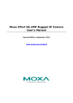
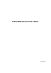
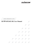
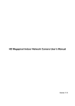
HD Waterproof Network Dome Camera
User’s Manual
Version 1.0.1
2014-08-07
Welcome
Thank you for purchasing our network camera!
This user's manual is designed to be a reference tool for your system.
Please keep this start guide well for future reference.
Please open the accessory bag to check the items one by one in accordance with the list below.
Contact your local retailer ASAP if something is missing or damaged in the bag.
Before
your
operation
please
read
the
following
instructions carefully.
1. Electrical safety
All installation and operation here should conform to your local electrical safety codes.
The power shall conform to the requirement in the SELV (Safety Extra Low Voltage) and the
Limited power sour0e is rated 12V DC in the IEC60950-1. (Refer to general introduction)
Please note: Do not connect two power supplying sources to the device at the same time; it may
result in device damage!
We assume no liability or responsibility for all the fires or electrical shock caused by improper
handling or installation.
We are not liable for any problems caused by unauthorized modification or attempted repair.
2. Transportation security
Heavy stress, violent vibration or water splash are not allowed during transportation, storage and
installation.
3. Installation
Do not apply power to the camera before completing installation.
Please install the proper power cut-off device during the installation connection.
Always follow the instruction guide the manufacturer recommended.
4. Qualified engineers needed
All the examination and repair work should be done by the qualified service engineers.
We are not liable for any problems caused by unauthorized modifications or attempted repair.
5. Environment
This series network camera should be installed in a cool, dry place away from direct sunlight,
inflammable, explosive substances and etc.
Please keep it away from the electromagnetic radiation object and environment.
Please make sure the CCD (CMOS) component is out of the radiation of the laser beam device.
Otherwise it may result in CCD (CMOS) optical component damage.
Please keep the sound ventilation. Do not allow the water and other liquid falling into the camera.
Thunder-proof device is recommended to be adopted to better prevent thunder. The grounding
studs of the product are recommended to be grounded to further enhance the reliability of the
camera.
6. Daily Maintenance
Please shut down the device and then unplug the power cable before you begin daily
maintenance work. Do not touch the CCD (CMOS) optic component. You can use the blower to
clean the dust on the lens surface.
Always use the dry soft cloth to clean the device. If there is too much dust, please use the water
to dilute the mild detergent first and then use it to clean the device. Finally use the dry cloth to
clean the device.
Please put the dustproof cap to protect the CCD (CMOS) component when you do not use the
camera.
Dome enclosure is the optical component, do not touch the enclosure when you are installing the
device or clean the enclosure when you are doing maintenance work.
Please use professional optical clean method to clean the enclosure. Improper enclosure clean
method (such as use cloth) may result in poor IR effect of camera with IR function.
7. Accessories
Be sure to use all the accessories recommended by manufacturer.
Before installation, please open the package and check all the components are included.
Contact your local retailer ASAP if something is broken in your package.
Accessory Name
Amount
Network Camera Unit
1
User’s Manual
1
CD
1
installation package
1
certification
1
Content
Basic Introduction
1
1. Overview
1
2. Feature List
1
Structure
3
1. Multiple-function Combination Cable
3
2. Framework and Dimension
4
3. Bidirectional talk
5
3. Alarm Setup
6
Device Installation
Quick Configuration Tool
8
11
1. Overview
11
2. Operation
11
Web Connect and Setting
14
1. IE Web browser setting
14
2. Login and Logout
14
FAQ
17
Appendix Toxic or Hazardous Materials or Elements
18
Basic Introduction
1.
1.
2.
3.
4.
5.
6.
Overview
This series cameras combine traditional cameras and network video technology. It is a
collection of video data collection and transmission in one does not require any auxiliary
equipment can be connected to the Internet. This series camera uses a standard H.264 video
compression technology to ensure maximum video quality.
This series of infrared night vision camera support functions, in the night of the environment,
through the use of this product is suitable for low-light monitoring infrared light, to ensure
ongoing monitoring under low light conditions.
Waterproof design meets IP66 grade, good waterproof function ensures that the device is
working outdoors.
This product can be used alone or for the network area, when it is used alone, you can
connect it to the Internet, using a network client to configure it and browse.
Since this series many styles, complete functions, this series cameras are widely used in
offices, banks, road monitoring, and many other environments.
Explosion levels IK10.
2. Feature List
User
Management
Storage
Management
Data transfer
Network
Monitoring
Program
Network
Management
Power
Accessibility
Different user permissions are grouped division, to ensure that each user
belongs to a specific set of permissions.
normal user rights will not exceed the highest authority.
Support by configuring alarm clock upload or store.
Support recording function recorded files are stored in the PC specify the
directory location.
support network storage technologies, such as FTP storage.
Data transmission via POE line.
support video data is sent to the network all the way to the terminal and
then decoded. Delay time in less than 200mm (need to match the network
bandwidth to support).
maximum support 10 simultaneous connections and 32Mbps output
bandwidth. Once the threshold is exceeded bandwidth, the system will
reject new connection requests.
Supports multiple video transport protocols: HTTP, TCP, UDP, MULTICAST,
RTP / RTCP, RTSP and etc.
Support web page access means.
Support configuration and management via Ethernet network camera
parameters.
Support webpage sand client management device.
Support a variety of protocols.
Support external 12V DC power adapter.
Optional POE power supply.
support logging.
Support real-time display system resource information and running status.
Support day mode, night mode, active mode and passive mode and other
modes.
Support picture parameter settings such as the electronic shutter and gain
settings.
screen backlight compensation: automatic segmentation of the region to
achieve the BLC area adapt to the current brightness.
Supports digital wide dynamic adjustment.
Support video digital watermarking function, to avoid being maliciously
modified video equipment.
Support dual-stream.
Table 1-1 Feature List
Structure
1. Multiple-function Combination Cable
You can refer to the following figure for multiple-function combination cable information. See
Figure 2-1.
Figure 2-1 Multiple-function combination cable
Please refer to the following sheet for detailed information.
No.
Port Name
Function
VIDEO OUT
Video
output
port
AUDIO IN
Audio
input port
Audio
input
3.5mm
JACK port
Input audio signal from devices such as
pick-up
AUDIO OUT
Audio
output
port
Audio
output
3.5mm
JACK port
Output audio signal to the passive
device such as earphone
4
RS485
Connect to
devices
/
Connect the RS - 485 devices, like a
cloud
platform
decoder
(fully
functional model specific)
5
LAN
Network
port
Ethernet
port
1
2
3
Connection
BNC
Note
Output analog video signal. It can
connect to the TV monitor to view the
video. Standard BNC interface.
Connect to standard Ethernet cable.
Support PoE.
No.
Port Name
Function
Connection
Note
6
ALARM_IN
I/O
(red)
/
Alarm input port . It is to receive the
on-off signal from the external alarm
source.
ALARM_OUT
I/O
port(green
)
/
Alarm output port. It is to output the
alarm signal to the alarm device.
normal open alarm output port.
8
POWER
Power
input port
9
RESET
Reset
button
7
port
Power port. Input DC 12V power.
Power supply please use matching
voltage regulator power supply.
The reset button is to restore device
factory default setup. press the reset
button for 3 seconds to reset or thread.
/
Please refer to the follow sheet for detailed I/O port information.
Port Name
SN
Name
Note
+
ALARM_IN
Alarm input port 1. It is to receive the on-off
signal from the external alarm source.
-
GND
Ground port
+
ALARM_OUT
Alarm output port. It is to output the alarm
signal to the alarm device.
-
GND
Ground port
ALARM_IN
ALARM_OUT
2. Framework and Dimension
Please refer to the following two figures for dimension information. The unit is mm. See Figure 22 and Figure 2-3.
Figure 2-2 Dimension 1
Figure 2-3 Dimension 2
3. Bidirectional talk
Device-end to PC-end
Device Connection
Please connect the speaker or the MIC to the audio input port of the device. Then connect the
earphone to the audio output port of the PC.
Login the Web and then click the Audio button to enable the bidirectional talk function.
You can see the button becomes orange after you enabled the audio talk function.
Click Audio button again to stop the bidirectional talk function.
Listening Operation
At the device end, speak via the speaker or the pickup, and then you can get the audio from the
earphone or sound box at the pc-end.
PC-end to the Device-end
Device Connection
Connect the speaker or the MIC to the audio input port of the PC and then connect the earphone
to the audio output port of the device.
Login the Web and then click the Audio button to enable the bidirectional talk function.
You can see the button becomes orange after you enabled the audio talk function.
Click Audio button again to stop the bidirectional talk function.
Please note the listening operation is null during the bidirectional talk process.
Listening Operation
At the PC-end, speak via the speaker or the pickup, and then you can get the audio from the
earphone or sound box at the device-end.
3. Alarm Setup
The alarm interface is shown as in Figure 2. Please follow the steps listed below for local alarm
input and output connection.
1) Connect the alarm input device to the alarm input port of the I/O cable.
2) Connect the alarm output device to the alarm output port+ and alarm out - The alarm output
port supports NO (normal open) alarm device only.
3) Open the Web, go to the Figure 2-4. Please set the alarm input + port for the first channel of
the I/O cable alarm out port +. The alarm input + is for the I/O cable.
4) Set the WEB alarm output. The alarm output + is for the alarm output port of the device. It is
the alarm out port + pin of the I/O cable.
Figure 2-4 Alarm
Please refer to the following figure for alarm input information. See Figure 2-5.
Alarm input: When the input signal is idle or grounded, the device can collect the different
statuses of the alarm input port. When the input signal is connected to the 5V or is idle, the
device collects the logic “1”. When the input signal is grounded, the device collects the logic “0”.
Figure 2-5 Alarm input
Please refer to the following figure for alarm output information. See Figure 2-6.
Port ALARM_COM and Port ALARM_NO composes an on-off button to provide the alarm output.
If the type is NO, this button is normal open. The button becomes on when there is an alarm
output.
If the type is NC, this button is normal off. The button becomes off when there is an alarm output.
Figure 2-6 Alarm output
Device Installation
Important: Please make sure the installation surface can min support the 3X weight of the camera
and the bracket.
Please follow the steps listed below to install the device. Please refer to Figure 3-1 for reference.
1 The installation drawing paste onto the ceiling or wall.
2 The selection of the mounting holes according to the installation drawing, please.
3 Open the accessories package, choose insert mounting holes expansion bolt.
4 Remove the screws from the accessory kit, the installation holes on the bracket to ensure that
the equipment is completely fixed to the mounting surface will not fall off. The device can be
moved around the sun visor, so please confirm that the device has been fixed after installation
surface will not slip or fall off, choose the appropriate length, locking bolts visor.
5 connect the appropriate cables.
6 Use a cross head screwdriver loosen the adjusting screw
7 Adjust the direction of the equipment, in the display shows images of the corresponding
picture requirements such as location and clarity.
8 Use a cross head screwdriver lock the adjusting screw.
Figure 3-1 Device installation illustration
Manual Zoom Lens Focus Operation
The manual zoom lens focus interface is shown as in Figure 3- 2.
Adjusting screw E
Adjusting screw F
Figure 3- 2 Zoom lens
Step 1
Slightly loosen the adjusting screw E and push the adjust screw E to make it swing. Adjust the
lens focus to the proper position according to the displayed video.
Step 2
Slightly loosen the adjusting screw F and push the adjust screw F to make it swing. Adjust the
lens to get the clear video and then fix the adjusting screw firmly.
Step 3
When you are securing the adjusting screw F, you can see the video may become blur. Please
push the adjusting screw E to adjust the video slightly. Please secure the adjust screw E if you get
a clear video.
Quick Configuration Tool
1. Overview
Quick configuration tool can search current IP address, modify IP address. At the same time, you
can use it to upgrade the device.
Please note the tool only applies to the IP addresses in the same segment.
2. Operation
Double click the “Upgrade Tools 1.3.1.exe” icon, you can see an interface is shown as in Figure 4-1.
In the device list interface, you can view device IP address, Status, Protocol, Software
Version ,MAC address and etc.
Figure 4-1 Search interface
If you would like to modify the camera's IP address, you can double-click on the listed device, the
interface appears as shown
Figure 4-2 Login prompt
Upgrade the following interface; just on the package can upgrade file import
Figure 4-3 Main interface
Web Connect and Setting
This series network camera product supports the Web access and management via PC.
Web includes several modules: monitor channel preview, system configuration and etc.
1. IE Web browser setting
Open the IE browser (IE 8 or later recommended browsers better). First use of the equipment,
please enter the IE tool configuration interface, shown in Figure 5-1.
Figure 5-1 Configuration interface
[Tools] → [Internet Options] → [Security] → [Custom Level security settings, adjust the ActiveX
options shown in Figure 5-2 Figure 5-3.
Figure 5-2 ActiveX controls configuration 1
Figure 5-3 ActiveX controls configuration 2
After the setting ,please follow the steps listed below for network connection.
Make sure the network camera has connected to the network properly and make sure you have
add the network segment 1.
Please set the IP address, subnet mask and gateway of the PC and the network camera
respectively. Network camera default IP address is 192.168.1.108. Subnet mask is 255.255.255.0.
Gateway is 192.168.1.1
Use order ping ***.***.***.***(* network camera address) to check connection is OK or not.
2. Login and Logout
Open IE and input network camera address in the address bar. See Figure 5-4.
Figure 5-4 IP address
Login first need to download AcitveX IE interface controls, download link will appear below the
login box shown in Figure 5-5.
Figure 5-5 Active Control Download
After successful installation control device for the first time are required to complete the run
logon controls, specific steps in the following figure
Figure 5-6 Control Download Options
Figure 5-7 Run ActiveX
Figure 5-8 control run options
Figure 5-9 control installation
Enter the account password in the pop-up login dialog (default account: admin, default password:
admin).
The following screen is displayed after a successful login, you can immediately configure all the
equipment.
Figure 5-10 Device Interface Preview
FAQ
Troubles
Troubleshoot
I cannot boot up the device.
Please click RESET button for at least five
seconds to restore factory default setup.
the system is running very slow,
memory fluctuated non-stop changing
This is due to the graphics driver not well
supported due to graphics performance. Please
upgrade the graphics card driver to the latest
version.
I cannot use the disk as the storage
media.
When disk information is shown as hibernation
or capacity is 0, please format it first (Via Web).
I cannot
network.
via
If you use the web upgrade can’t success, use
the tool please.
I am directly connected computer video
browsing, I found the video often
Freeze, but slowly growing delays.
Check whether the network access standards,
such as replacing a tested qualified network
cable.
Why do I use IE to log in, you can see
the login screen, but that is not to log
into?
Please check IE's Internet Options -> Privacy ->
Settings, make sure the area is set to "Medium"
or lower.
To guarantee setup update
After you modified the important setup, please
reboot the device via the software to make sure
the setup has been updated to the storage
medium.
Power adapter
The general power adapter can work ranging
from 0℃ to 40 ℃.The device may result in
unstable power supply when the temperature
exceeds the working temperature.
upgrade
the
device
Please replace an industry-level power adapter
if you are using in the harsh environments.
Why do I login page, the video window
cannot display video, but the rate is still
the size of a real-time update
Please upgrade your graphics card driver to the
latest version.
I am using Window XP operating
system, when my client tens road
record, the system will become very
slow, and often lose data, which is why
When recording dozens of road, we recommend
using win7 or more operating systems for
recording.
I want to play my video data, but I
cannot search for what
Check the following points: 1 video directory is
added correctly. 2 device time is synchronized
with the PC. 3 is already enabled video.
Appendix Toxic or Hazardous Materials or Elements
Component Name
Toxic or Hazardous Materials or Elements
Pb
Hg
Cd
Cr VI
PBB
PBDE
Circuit Board Component
○
○
○
○
○
○
Device
Construction
Material
Wire and Cable
○
○
○
○
○
○
○
○
○
○
○
○
Packing Components
○
○
○
○
○
○
Accessories
○
○
○
○
○
○
O: Indicates that the concentration of the hazardous substance in all homogeneous materials in
the parts is below the relevant threshold of the SJ/T11363-2006 standard.
X: Indicates that the concentration of the hazardous substance of at least one of all
homogeneous materials in the parts is above the relevant threshold of the SJ/T11363-2006
standard. During the environmental-friendly use period (EFUP) period, the toxic or hazardous
substance or elements contained in products will not leak or mutate so that the use of these
(substances or elements) will not result in any severe environmental pollution, any bodily injury or
damage to any assets. The consumer is not authorized to process such kind of substances or
elements, please return to the corresponding local authorities to process according to your local
government statutes.
Note:
This user's manual is for reference only. Slight difference may be found in user interface.
All the designs and software here are subject to change without prior written notice.
If there is any uncertainty or controversy, please refer to the final explanation of us.
Please visit our website or contact your local service engineer for more information.