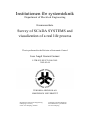
1
Institutionen för systemteknik
Department of Electrical Engineering
Examensarbete
Survey of SCADA SYSTEMS and
visualization of a real life process
Thesis performed in the Division of Automatic Control
Jose Angel Gomez Gomez
LITH-ISY-EX-ET-0246-2002
2002-05-04
TEKNISKA HÖGSKOLAN
LINKÖPINGS UNIVERSITET
Department of Electrical Engineering
Linköping University
S-581 83 Linköping, Sweden
Linköpings tekniska högskola
Institutionen för systemteknik
581 83 Linköping
Survey of SCADA SYSTEMS and
visualization of a real life process
Examensarbete utfört i Reglerteknik
vid Linköpings tekniska högskola
av
Jose Angel Gomez Gomez
LiTH-ISY-EX-ET-0246-2002
Handledare: David Lindgren
Examinator: Inger Klein
Linköping 2002-05-04
Avdelning, Institution
Division, Department
Datum
Date
2002-06-04
Institutionen för Systemteknik
581 83 LINKÖPING
Språk
Language
Svenska/Swedish
X Engelska/English
Rapporttyp
Report category
Licentiatavhandling
X Examensarbete
C-uppsats
D-uppsats
ISBN
ISRN LITH-ISY-EX-ET-02462002
Serietitel och serienummer ISSN
Title of series, numbering
Övrig rapport
____
URL för elektronisk version
http://www.ep.liu.se/exjobb/isy/2002/246/
Titel
Title
Översikt över SCADA-system och visualisering av verklig process
Survey of SCADA systems and visualization of a real life process
Författare Jose Angel Gomez Gomez
Author
Sammanfattning
Abstract
Most of the industrial plants has a control center where is installed a SCADA (Supervisory
Control And Data Acquisition) application. At the moment, it exists a great offer of
acquisition, supervision and control of software and the evolution of this software follows
a triple tendency: intercommunication between applications, standardization of the
communications with the field devices and adoption of the communication surroundings.
The report is divided in two parts. In the first the reader can learn the basic ideas of
SCADA system and find the most important SCADA software available today. InTouch
7.1 and WinCC have been studied in more depth because they are the most successful
software. In the second part is described the visualization of a real life process, it is the
visualization of a toy car factory allocated in Linköping?s University and how
interconnected the visualization process with the PLC (Programmable Logic Controller).
In the report also are described the basic components needed to realize the visualization of
any process involving PLCs.
Nyckelord
Keyword
Control, SCADA, PLC
Detta dokument hålls tillgängligt på Internet – eller dess framtida ersättare
– under en längre tid från publiceringsdatum under förutsättning att inga
extra-ordinära omständigheter uppstår.
Tillgång till dokumentet innebär tillstånd för var och en att läsa, ladda
ner, skriva ut enstaka kopior för enskilt bruk och att använda det oförändrat
för ickekommersiell forskning och för undervisning. Överföring av
upphovsrätten vid en senare tidpunkt kan inte upphäva detta tillstånd. All
annan användning av dokumentet kräver upphovsmannens medgivande.
För att garantera äktheten, säkerheten och tillgängligheten finns det
lösningar av teknisk och administrativ art.
Upphovsmannens ideella rätt innefattar rätt att bli nämnd som
upphovsman i den omfattning som god sed kräver vid användning av
dokumentet på ovan beskrivna sätt samt skydd mot att dokumentet ändras eller
presenteras i sådan form eller i sådant sammanhang som är kränkande för
upphovsmannens litterära eller konstnärliga anseende eller egenart.
För ytterligare information om Linköping University Electronic Press
se förlagets hemsida http://www.ep.liu.se/
The publishers will keep this document online on the Internet - or its possible
replacement - for a considerable time from the date of publication barring
exceptional circumstances.
The online availability of the document implies a permanent permission for
anyone to read, to download, to print out single copies for your own use and to
use it unchanged for any non-commercial research and educational purpose.
Subsequent transfers of copyright cannot revoke this permission. All other uses
of the document are conditional on the consent of the copyright owner. The
publisher has taken technical and administrative measures to assure
authenticity, security and accessibility.
According to intellectual property law the author has the right to be
mentioned when his/her work is accessed as described above and to be
protected against infringement.
For additional information about the Linköping University Electronic Press
and its procedures for publication and for assurance of document integrity,
please refer to its WWW home page: http://www.ep.liu.se/
© Jose Angel Gomez Gomez
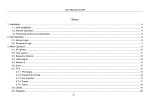
INDEX
Abstract__________________________________________________________________ 6
Acknowledgments _________________________________________________________ 7
I.INTRODUCTION ____________________________________________________ 8
I.1 Background____________________________________________________________ 9
I.2 Overview of SCADA SYSTEMS__________________________________________ 10
I.2.1 Functionality ______________________________________________________________10
I.2.2 Requirements ______________________________________________________________10
I.2.3 SCADA Modules___________________________________________________________11
I.3 Project purpose________________________________________________________ 12
I.3.1 Survey ___________________________________________________________________12
I.3.2 Implementation ____________________________________________________________12
I.4 Reader’s Guide ________________________________________________________ 13
II SURVEY _________________________________________________________ 14
II.1 Description___________________________________________________________ 15
III. IMPLEMENTATION______________________________________________ 16
III.1 Description of application______________________________________________ 17
III.1.1 Hardware________________________________________________________________17
III.1.2 Software ________________________________________________________________19
III.1.2.1 Intouch. _____________________________________________________________19
III.1.2.2 Siemens WinCC ______________________________________________________19
III.1.3 Software used ____________________________________________________________20
III.2 Description Visualization Environment __________________________________ 21
III.2.1 Visualization mode ________________________________________________________21
III.2.2 Simulation mode __________________________________________________________23
III.3 Link the application to Kepware´s Server. ________________________________ 27
III.4 How to run: _________________________________________________________ 29
III.4.1 Software needed and required Files ___________________________________________29
III.4.2 Running the application ____________________________________________________29
III.5 Conclusions _________________________________________________________ 30
Bibliography _____________________________________________________________ 31
APPENDIX I. Main SCADA systems ________________________________________ 32
Factory Link 7 _________________________________________________________________32
Paradym-31 ___________________________________________________________________32
WizFactory ___________________________________________________________________33
Cimplicity Plant Edition _________________________________________________________33
Genesis32_____________________________________________________________________34
Intellution Dynamics ____________________________________________________________34
LabView _____________________________________________________________________35
HMI/SCADA Paragon ___________________________________________________________35
FactoryFloor Software ___________________________________________________________36
RSView32 ____________________________________________________________________36
APPENDIX II. WinCC HMI _______________________________________________ 37
APPENDIX III.InTouch 7.1. Overview. ______________________________________ 42
APPENDIX IV. Introduction to KEPServerEX ________________________________ 47
APPENDIX V. Tagname Dictionary _________________________________________ 52
Abstract
Abstract
Most of the industrial plants has a control center where is installed a
SCADA (Supervisory Control And Data Acquisition) application. At the moment,
it exists a great offer of acquisition, supervision and control of software and the
evolution of this software follows a triple tendency: intercommunication between
applications, standardization of the communications with the field devices and
adoption of the communication surroundings.
The report is divided in two parts:
In the first the reader can learn the basic ideas of SCADA system and
find the most important SCADA software available today. InTouch 7.1 and
WinCC have been studied in more depth because they are the most successful
software.
In the second part is described the visualization of a real life process, it
is the visualization of a toy car factory allocated in Linköping’s University and
how interconnected the visualization process with the PLC (Programmable
Logic Controller).
In the report also are described the basic components needed to realize
the visualization of any process involving PLCs.
6
Acknowledgments
Acknowledgments
Here I would like to thank people who have helped and supported me
during the work of this thesis. First of all thanks to my director David Lindgren
for the guidance through the thesis and for all the help that he brought me.
Thanks to my examiner Inger Klein and to César Ramos, my codirector in
Spain.
Thanks to all the Spanish, German, all Erasmus in general, and Swedish
people here in Linköping for make my stay here better, specially those that have
been close to me in all good and bad moments: Erik, Veroka, Fer, Figu, Marian,
Galochopa, Alfredo, Marcus, Isak …
And I would like to thank the most important people in my life, my family
and Aitana that have been with me from the distance all the time.
Thank you for all
7
I.INTRODUCTION
8
Background
I.1 Background
In the Labotek, an undergraduate course laboratory at the department of
electrical engineering, of Linköping’s University, there is implemented a factory
of toy cars made with LEGO.
This factory simulates the assembly line of cars and is constituted by a
PLC (Programmable Logic Controller) that controls the process, a PC
connected to the PLC, a control panel that is used to act on the factory and the
own factory built entirely with LEGO.
With this project it is sought to study, which is the most appropriate
software tool to carry out the visualization on a computer of this process and to
develop a SCADA system that allows this visualization.
9
SCADA SYSTEMS.Overview
I.2 Overview of SCADA Systems
SCADA comes from the acronyms "Supervisory Control And Data
Acquisition", that is data acquisition and supervision control. It is a software
application specially designed to work on computers in the production control,
providing communication with the devices (independent controllers,
programmable robots, etc.) and controlling the process from the screen of the
computer. In addition, it provides all the information that is generated in the
process to diverse users, as much as the same level as to other supervisors
within the company: quality control, supervision, maintenance, etc.
In this type of systems it usually exists a computer, which carries out
tasks of supervision and management of alarms, as well as data processing
and process control. The communication is made by means of special buses or
LAN networks. All this is executed normally in real time, and is designed to give
to the plant operator the possibility of supervising and controlling these
processes. The necessary programs, and in this case the additional hardware
that is needed, is generally denominated SCADA.
I.2.1 Functionality
A package SCADA must be ready to offer the following functionality:
•
•
•
•
Possibility of creating alarm panels, which demand the presence of
the operator to recognize a shutdown or situation of alarm, with
registry of incidences.
Generation of plant signal history that can be used for other
programs.
Execution of programs, that modify the control law, annul or even to
modify the tasks associated to the robot, under certain conditions.
Possibility of numerical programming, that allows arithmetic
calculations of high resolution on the CPU of the computer.
With them, applications for computers can be developed, with capture of
data, analysis of signals, presentations in screen, shipment of results to disc
and printer, etc.
I.2.2 Requirements
A SCADA must fulfil several objectives so that its perfectly installation is
taken advantage of:
•
•
They must be systems of open architecture, able to grow or to adapt,
according to the changing, the company necessities.
They must communicate with total facility and transparently the user
with the plant equipment and the rest of the company.
10
SCADA SYSTEMS.Overview
•
They must be programs simple to install, without excessive
exigencies of hardware, and easy to use, with user-friendly interfaces.
I.2.3 SCADA Modules
The modules or software blocks that allow the activities of acquisition,
supervision and control are the following ones:
•
•
•
•
•
Configuration: it allows the user to define the work surroundings of
his SCADA being adapted to the particular application that is desired
to develop.
Graphical interface of the operator: it provides to the operator the
functions of control and supervision of the plant. The process
imagines, by means of synoptic graphs, is stored in the computer
process and generated from the publisher, incorporated in the
SCADA or concerned from another application during the
configuration of the package.
Module of process: it executes the pre-programmed actions of
control from the present values of the read variables.
Management and data file: it is in charge of the storage and ordered
processing of the data, so that another application or device can have
access to them.
Communications: it is in charge of the transference of information
between the plant and the hardware architecture that supports the
SCADA, and between this one and the rest of computer elements of
management.
11
Project purpose
I.3 Project Purpose
The project consists of two complementary parts:
I.3.1 Survey
The first part consists of making an investigation to discover the software
tools developed by the main manufacturers of PLC´s available today.
This investigation consists of analysing the software developed by the
main manufacturers of PLC´s (MITSUBISHI, SIEMENS, OMRON, etc), or of
software (WONDERWARE, etc) visualize, indicating the characteristics of each
program.
I.3.2 Implementation
The second part of the project consists of using the study made
previously; select a tool, the one that is considered appropriate to make the
visualization, and to apply it to a real application.
Develop a SCADA that allows supervising and to control the “Lego car
factory” that is in the Labotek of Linköping’s University. For it the following
points must be solved:
•
•
•
Used tool: selection of the tool in which application SCADA will be
developed. Study of this tool, possibilities that offer, limitations and
operations.
Application developing: create an application for the supervision,
monitorization and control of the Lego car Factory.
Connectivity between the PLC and the computer: to select the
software adapted for the data transmission between the PLC and the
computer.
12
Readers guide
I.4 Reader’s Guide
This report is divided in two parts that correspond with the mains of this
project.
In the chapter SURVEY, is explained how the study of the software has
been carried out and some references to the corresponding appendices, in case
of needing more information, are included.
In the chapter IMPLEMENTATION, the following aspects are included:
•
•
•
•
Brief description of the application.
Components selected for the realization of the application as well as
the motivations that have taken to their selection.
Description of the visualization environment.
User's Manual for the use of the application.
13
II SURVEY
14
Description
II.1 Description
In this study I have tried to discover all the existing tools today for the
visualization of industrial processes. For this I have visited all the pages of
manufacturers so much of hardware (PLC) as of software (SCADA systems)
with the purpose of discovering the major part of possible software packages.
I have visited WEB pages of PLC manufacturers such as:
•
•
•
•
•
•
•
Omron
Allen
GE Fanuc
Mitsubishi
Siemens
Hitachi
Etc.
And software as:
•
•
•
•
•
•
•
USDATA
Advantech
Iconics
National Instruments
Rockwell Automation
Wonderware
Etc.
For more information about some package see the APPENDIX I. All the
information collected in this appendix has been taken from the web pages of the
developers.
The packages WinCC (appendix 2) and InTouch (appendix 3) have been
emphasized because they were considered the most important ones.
All the information collected in this section has been founded in the web
using web pages like google, yahoo, etc.
15
III. IMPLEMENTATION
16
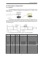
Description of application
III.1 Description of Application
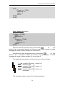
III.1.1 Hardware
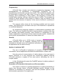
The whole system consists of the factory of cars, the PLC with the control
panel and a PC. All these components are connected as it is shown in the
following figure.
Control panel
Car factory
PLC
PC
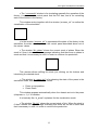
The purpose of the SCADA application that shall be implemented is to
show in which state is the factory of cars using the information picked up of the
sensors that are in the factory. The disposition of these sensors can be seen in
the following figure:
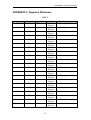
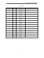
The meaning of each one can be seen it in the following table.
Tagname
Item
G1
G2
G3
G4
G5
G6
G7
G8
G9
G11
G12
F1
F2
F3
F4
F5
F6
X17
X15
X13
X11
X7
X5
X3
X1
X24
X23
X22
X16
X14
X12
X10
X6
X4
Logic
value
L
L
L
L
L
L
L
L
H
H
H
H
H
L
L
L
H
Type
Comment
I/O Discrete
I/O Discrete
I/O Discrete
I/O Discrete
I/O Discrete
I/O Discrete
I/O Discrete
I/O Discrete
I/O Discrete
I/O Discrete
I/O Discrete
I/O Discrete
I/O Discrete
I/O Discrete
I/O Discrete
I/O Discrete
I/O Discrete
Ejector plates back
Ejector plates forward
Stop at bit-stop back
Stop at bit-stop forward
Ejector bits back
Ejector bits forward
Stop at press back
Stop at press forward
Press in top position
Turner receiver
Turner deliver
Stock plates empty
Stock bit empty
Chassis at bit-stop
Chassis at press
Chassis at turner
Signal from B
17
Description of application
Each sensor is activated or not depending where the chassis or the
corresponding object is.
The PLC that controls the toy car factory is a MITSUBISHI FX SERIES
PROGRAMABLE CONTROLER, Model FX-16EX.
See also [6].
18
InTouch Vs WinCC
III.1.2 Software
In this thesis two of the main SCADA systems (InTouch and WinCC)
have been studied in more detail than the others, in order to determine the
advantages and disadvantages each one has.
III.1.2.1 Wonderware Intouch.
Wonderware InTouch is really easy to work with. You can build your
application and most of the functions just “point and click”.
Is possible to learn to work with InTouch is a short period of time and
there in not many major errors that you can do when build an application. It is
easy for the maintenance people to understand how to work with it and alter
pictures and connections.
It is easier to made Scripts for inexperienced programmer using InTouch
than WinCC because of the usage of pointers in the Scripts that can make your
application crash irregularly.
See also [1] and Appendix III.
III.1.2.2 Siemens WinCC
WinCC is well structured; the different functions of the SCADA are
divided into several different programs (picture program, alarm, tag logging,
reports, global scripts...). This is good because in a big project it will get easier
to get an overview application.
WinCC is also very open. This is useful when you must do something out
of the standard. Then you make C-Scripts that calls the different API´s
(Application Program Interface) and make your own functions in a very
standardized way.
The UADMIN (User Administration) is also a good example on the
structure. You can make different permissions that can use on the objects. Then
you make users groups and if you add a user it get a default permissions of the
group but you can easily add/remove permissions on the individual user. In
InTouch you must have some sort off authorizations value and give the user a
certain value.
Some disadvantages of WinCC are:
•
•
•
It takes time to learn.
In a small project it will take time to configure.
The WinCC application demands a very powerful computers and the
server must be a dedicated server.
See also [2] and Appendix II.
19
Software and hardware used
III.1.3 Software Used
The execution and development surroundings are under Microsoft
Windows NT Workstation 4.0.
The following software have been chosen for developing the application:
•
The main software used is InTouch 7.1 (Wonderware), a tool for
creating SCADA Systems. We have chosen InTouch for the next
reasons:
o Wonderware InTouch is really easy to work with and enough
powerful for develop this application. You can build your
application and most of the functions just “point and click”.
o Is possible to learn to work with InTouch is a short period of time
and there in not many major errors that you can do when build an
application. It is easy for the maintenance people to understand
how to work with it and alter pictures and connections.
o It is easier to made Scripts for inexperienced programmer using
InTouch than WinCC because of the usage of pointers in the
Scripts that can make your application crash irregularly. See a
brief comparison between WinCC and InTouch in appendix VI.
•
For the connection and Data acquisition KEPServerEX (kepware)
server have been used, because is a tool easy to configure and use.
In addition KEPServerEX include drivers for use with a big quantity of
PLC manufacturers like: Siemens, Mitsubishi A Series, Allen-Bradley,
GE Fanuc, Omron, etc. See more information about KEPServerEX in
the Appendix IV and [8].
•
Also graphical packages are used for creation and adjustment of
images like Microsoft Paint or Adobe Photoshop.
20
Description visualization environment
III.2 Description Visualization Environment
Since it has been said before to make the visualization InTouch 7.1 has
been used.
The visualization process is compound by several windows and it can run
in two modes: visualization mode and simulation mode. Following is described
the application developed using InTouch 7.1.
• The “Open Windows” is used to select the mode of operation:
visualization mode or simulation mode. Also it is possible to open all those
windows that are hidden in this moment for a determinate mode:
•
•
•
•
Visualization mode.
Simulation mode.
Press (visualization mode) / No plates (simulation mode).
Alarm (visualization mode) / No plates (simulation mode).
If we are working in visualization mode the options NO plates and NO
bits are invisible, in the simulation mode the invisible windows are Press and
Alarm.
visualization mode
simulation mode
III.2.1 Visualization Mode
The visualization mode shows the state of each sensor in the factory and
graphically represents it.
It is made up of the following windows:
• The window “process” is the most important because you can see
throughout which the each element state of the car factory, representing
graphically the sensors value that provides the I/O server.
In the following figure the window “process” is shown.
21
Description visualization environment
To achieve the visualization, the following representation has been used.
In this example you can see how the G2 and G1 sensor information is
represented in order to move the ejector plates ( .
in the figure above).
Is visible if: Ejector
plates forward
Is visible if: Ejector
Plate’s middle
Is visible if: Ejector
plates back
These are the conditions to show the ejector plates state depending on
G1 and G2.
G1 == 1 AND G2 == 0;
G1 AND G2;
G1 == 0 AND G2 ==1;
• The window “w_press” is for showing the state of the press, and it can
have two values:
Press on top position.
Press Down.
This window appears automatically when the
chassis arrives to the press (F4 == 1), if it is hidden
clicking the option in the “open_windows”.
• The window “Alarm” shows a history of the
22
or
Description visualization environment
alarms that have been taken place in the system, by different causes:
•
•
The plates Stock is empty.
The bit Stock is empty.
Also it is possible to see the alarms that have been recognized (clicking
ack button) and those that the operator did not recognize.
III.2.2 Simulation Mode
The simulation mode is for simulating the operation of the factory, but
now the state represented is totally independent of the PLC. The state is
produced by using the “commands” window.
For achieving the simulation some variables and scripts have been
defined in order to move all the components of the application.
For instance for simulating the movement of the plates ejector the
following variables have been defined:
•
•
•
•
plates: used for know where the plates ejector is.
stockplates: current plates stock.
platescha: plates is before the bit injector.
Bit: the chassis is in the stop of the bit injector.
In function of these variables value we represent the ejector plates. Also
a function called move_plates_back and move_plates_forward have been
defined, the squeleton of these functions are shown here.
move_plates_forward function
IF plates == 0 THEN
IF stockplates <= 0 THEN
Show("NO_plates");
start = 0;
ELSE
stockplates = stockplates - 1;
plates = 1;
platescha = 1;
bit = 0;
ENDIF;
23
Description visualization environment
ELSE
IF plates == 1 THEN
platescha = 2;
plates = 2;
bit =0;
ENDIF;
ENDIF;
move_plates_dw function
IF plates == 2 THEN
plates = 1;
platescha = 0;
ELSE
IF plates == 1 THEN
plates =0;
platescha = 0;
ENDIF;
ENDIF;
Each time that the operator click on the button
on
the
plates in the “commands” window, the function move_plates_forward is called
changing the value of plates variable if it is less than 2.
Also each time that the operator click on the button
on the
plates in the “command” window the function move_plates_back is called
changing the value of plates variable if it is more than 0.
The graphical representation of plates is shown in the next figure.
Is visible if: Ejector
plates forward
Is visible if: Ejector
plates medium
Is visible if: Ejector
plates back
plates == 2
plates == 1
plates == 0
The simulation mode is made of the following windows:
24
Description visualization environment
• The “commands” window is for simulating manually the operation of the
factory. It represents the control panel that the PLC has, and is for controlling
each of the motors in the factory.
This window works together with the window “process_rel” to realize the
visualization of the simulation.
• In the window “process_rel” is represented the state of the factory in the
simulation, the state now depend on the control panel described above not of
the sensor values.
• The window “No_plates” shows the current stock of plates. When the
stock is 0 then it shows an error message indicating that there are no plates in
stock and that it is necessary to refill it in order to continue the production.
This window allows refilling the stock just clicking on the buttons and
introducing the desired stock.
• The window “w_press sim” is for showing the state of the press in the
simulation mode, and it could be two values:
•
•
Press on top position.
Press Down.
This window appears automatically when the chassis arrive to the press
(chapress == 1), if it is hidden.
It is basically like “w_press” explained for the visualization mode.
• The window “No_bit” shows the current stock of bits. When the stock is
0 then it shows an error message indicating that there are no bits in stock and
that is necessary to refill it in order to continue the production.
25
Description visualization environment
This window allows refilling the stock just clicking on the buttons and
introducing the desired stock.
26
Link the application to Kepweare´s Server
III.3 Link the application to Kepware´s Server.
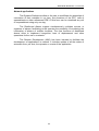
Once the visualization environment is developed. The following step is to
connect this environment with the PLC, to pick up the information of the
different sensors.
How to carry out the connection of the visualization environment with the
PLC using Kepware´s Server it is shown next step by step.
1. We have crated a single Access Name, which will be linked to the first
device in the KEPServer project. To do this select Special/Access
Names … in the WindowsMaker main menu in our application created
with InTouch 7.1.
2. Click add to add a new Access Name
3. Enter a unique Access Name; we enter MLPLC to access to the tags
on the server. The application name will always be “servermain”. The
Topic Name will be always the alias that we created for the first
device in our case “Channel1_device_1”.
4. As we use a DDE connection, this option must be selected and
advised only active item so we have to select this option.
Note: if we were connecting to a remote Pc then we would introduce its
name in Node Name.
Then the configuration panel for our application looks like:
As we only use one Access Name we can finish the configuration clicking
Close button to return to the project.
Now that we have created the link to the server we can add tags to the
Tagname Dictionary to access to the information of the PLC.
1. Select Special/Tagname Dictionary … from the WindowsMaker main
menu.
27
Link the application to Kepweare´s Server
2. Select a Tagname for the tag, for example “G1”, that it said to us if the
plate ejector is in the back position.
3. In the Tagname Dictionary, click on New to add a new tag. As all the
values that we are going to read/write are Boolean we define all
tagnames as an I/O Discrete, selecting this option clicking on the
button Type.
4. Click on Access Name… to select where the data for the tag that we
are defining will be coming from. We chose in all the cases “MLPLC”
because is the unique Access Name that we have defined in our
application, and because all the data will become from this point.
5. Click on Save to accept the new tag definition.
The figure shows the configuration window for the tagmane “G1”.
See the Appendix V where you can found all tags that we define for the
application.
28
How to run
III.4 How to Run:
III.4.1 Software needed and required Files
To be able to execute the application it is indispensable to have the
following software installed in the PC:
•
•
•
Microsoft Windows
Wonderware InTouch.
KEPServerEX
The files required are:
•
•
“Vis_lego”: file that contains the visualization carried out in InTouch.
“lego_server.opf”: file that contains the configuration of the server
OPC, necessary for the connection between the PLC and the
application.
III.4.2 Running the application
In order to execute the application it is necessary to follow the next steps:
1. Execute the KEPServerEX program.
2. Open the file “lego_server.opf” clicking File/Open from the main
menu.
Now that the OPC server is running is possible to execute the InTouch
application correctly and interact with all the windows that have been explained
before.
3. Open InTouch 7.1, installed in your computer.
4. The name of the application is “Vis_Lego”. Then, when InTouch is
opened select “Vis_lego” and click open button.
5. In a couple of seconds the application will be open.
To make the application run just you have to press on button “runtime”,
on the right side at the top of the window.
When the application is executed the first time only the window “process”
and the window “Open_window” are shown, but is easy to change this windows
selecting the window that you want to open just clicking on the “Open_window”
option.
29
Conclusions
III.5 Conclusions
In this project several SCADA Systems have been studied and InTouch
offers enough possibilities being a tool quite easy of using for what has been
considered the most appropriate for the realization of this project.
As for the implementation part when we work with PLC´s the most
difficult part of solving it is the one that refers to the interconnection PLC with
the PC.
During the realization of this project, due to diverse technical problems, it
was the part that more time has taken of solving.
30
Bibliography
Bibliography
[1] Information about InTouch
http://www.wonderware.com
[2] Information about WinCC
http://www.ad.siemens.de/hmi/html_76/products/software/wincc/index.htm
[3] Mitsubishi FX helps; provided together KEPServerEX I/O server.
[4] InTouch 7.1 User manual
[5] http://www.automatas.org/
[6] Styrning av LEGO-bilfabrik. En laboration i sekvensstyrning
[7] KepserverEx Client connectivity guide
http://www.yca.com/technical_information/appnotes/KTSM00012_OSI_PI_ConnectivityGuide.pdf
[8] Kepware Technologies
http://www.kepware.com/index.html
31
APPENDIX I. Main SCADA Systems
APPENDIX I. Main SCADA Systems
Note: The information collected in this appendix has been taken from the web
pages of main software developers.
Factory Link 7
SUPPLIER: USDATA (http://www.usdata.com/)
FactoryLink is a collection of software tools
used to build a variety of SCADA/HMI (Supervisory
Control
and
Data
Acquisition/Human-Machine
Interface) applications in the manufacturing and
process industries. It collects critical information from plant floor devices and
then distributes the data in real-time to decision-makers whether they are on the
plant floor, in the corporate office, or around the globe. FactoryLink provides
advanced data processing functionality such as alarming, trending and data
logging - allowing essential information to be provided to users and higher-level
business systems as needed.
Some features of FactoryLink 7 include:
•
•
•
•
•
Object-based configuration, external data import and standard
technologies result in the lowest total cost of ownership.
Many new tools are offered to create highly functional graphical user
interfaces.
Provides a large amount of pre-configured functionality that allows
you to achieve a working application in record time.
Supports OPC Client and Server for the collection and distribution of
data, giving manufacturers the most open real-time automation
system in the industry.
Microsoft SQL Server 7.0 is shipped with FactoryLink to provide
advanced data storage functionality out-of-the-box.
Paradym-31
SUPPLIER: Advantech (http://www.advantech.com/)
Advantech Paradym-31 is an IEC 1131-3
compliant
MS-Windows
based
graphical
programming environment which allows you to create, debug and manage realtime control programs like traditional Programmable Logic Controller (PLC)
languages. It contains a highly integrated collection of programming tools for
building PC-based control programs which run on Advantech ADAM-5510
control modules.
Combined with an Advantech ADAM-5510 controller, Advantech
Paradym 31 software provides a complete automation control solution for open
32
APPENDIX I. Main SCADA Systems
PC-based users. Your customers can use Advantech's PC-based control
solutions to build different systems based on customer needs.
WizFactory
SUPPLIER: eMation (http://www.emation.com/)
Complete solution for information and
automatization, it combines the discreet and the
continuous control with SCADA and Internet.
Between its components is Wizcon for Windows
and the Internet a powerful HMI/SCADA software package that delivers realtime and historical information from the plant floor to the boardroom and
beyond. It has been designed to expertly handle all the responsibilities of
SCADA with maximum flexibility and superb performance. It goes on to provide
secure, multi-level access to any user through Java-enabled Web browsers.
Another component is WizPLC, it is an open, standards-based, soft logic
solution for Windows NT. It is fully compliant with the IEC 61131-3 standards
and languages. WizPLC can be operated standalone as a PC-based control
system or in combination with Wizcon for a complete control and SCADA
solution. WizPLC has been successfully deployed in a variety of industries. By
offering integrated control development, execution and operator interface in one
package, WizPLC cuts application development time and maintenance costs,
increases performance and provides high data integrity, regardless of the
hardware used.
Cimplicity Plant Edition
SUPPLIER: GE Fanuc (http://www.gefanuc.com/)
CIMPLICITY Plant Edition provides
superior HMI and SCADA functionality and
establishes a solid foundation for Collaborative
Internet Manufacturing. True client/server
architecture and open-system design offer fast, easy integration with the ability
to grow from a single computer node to a plant-wide monitoring and control
system providing real-time information from the factory floor to all levels of the
enterprise.
CIMPLICITY HMI Plant Edition™ consolidates the collection of data from
your facility's sensors and devices, then transforms the data into dynamic text,
alarm and graphic displays. It gives users access to real-time information,
helping them make better decisions and prevent problems before they occur for
improved quality, productivity and profitability.
CIMPLICITY Plant Edition has more features and options than any other
automation software. These features, called Power Tools, are organized within
a Workbench that provides the easiest platform available to develop and
maintain your applications.
33
APPENDIX I. Main SCADA Systems
Genesis32
SUPPLIER: Iconics (http://www.iconics.com/)
GENESIS32TM Enterprise Edition was designed
from the ground up to take maximum advantage of
Microsoft’s DNA architecture, which includes; VBA,
COM, DCOM and WEB enabling ActiveX technology. OPC is at the core of the
ICONICS Award Winning family of 32 bit products and is the only product based
exclusively on OPC.
GENESIS32 offers a totally non-proprietary set of open and scalable
automation tools that provide the ultimate freedom of choice.
GENESIS32 is ideally suited for many applications requiring
Visualization, Supervisory Control, Data Acquisition, Advanced Alarming,
SPC/SQC, Report and Recipe Management and much more.
GENESIS32 seamlessly integrates with Batch, MES, MRP, MS Office
and Information systems. Create enterprise and distributed applications using
the latest OPC enabling technology. Interface to applications such as MS SQL,
Oracle, Access, Excel and E-mail
Intellution Dynamics
SUPPLIER: Intellution (http://www.intellution.com/)
It is a family of software for automatization
that constitutes one of the most powerful
solutions available in the industry. Account with diverse components of software
of high performance that provide solutions with automatization for HMI, SCADA,
virtual processes of Batch, PLC´s and applications of Internet.
IFIX is a SCADA and MMI system that offers complete visualization of
the process, storage and data management of process and control supervision.
IBatch consists of an oriented solution to Batch processes very typical of the
chemical, pharmaceutical industry, of drinks and foods. IWebServer is a
solution that qualifies the remote visualization of the processes by means of
Internet.
34
APPENDIX I. Main SCADA Systems
LabView
SUPPLIER: National Instruments (http://www.ni.com/)
With LabVIEW, you can rapidly create test,
measurement, control, and automation applications
using intuitive graphical development. Quickly create
user interfaces to interactively control your system.
Easily specify system functionality by assembling block diagrams. LabVIEW
combines ease of use, performance, and powerful functionality to deliver better
productivity for your immediate needs, while providing scalability for long-term
requirements.
HMI/SCADA Paragon
SUPPLIER: Nematron (www.nematron.com/)
The innovative Paragon HMI & SCADA
software package regulates control and
management of process information. Unlike
many PC-based SCADA system architectures, Paragon delivers highperformance and reliability in networked applications with a scaleable database
design.
Paragon supports seamless cross-platform communication among
operating systems from Windows NT to Windows 95 and OS/2 on the same
network. Its open modular design and dynamic connectivity features simplify
integration into enterprise-wide networks.
When coupled with Nematron's OpenControl PC-based control software,
Paragon offers a deterministic, fast real-time control system that can operate
the most complex batch, process, or hybrid control applications.
Its peer-to-peer and network architecture client/server design deliver data
integrity and system reliability. Server modules generate and store all critical
real-time and historical data, while high-speed client modules use the server
data to present information to people and other systems. Built-in mechanisms
allow data exchange with third-party applications through OPC, DDE, ActiveX,
communications standards, and programming languages.
35
APPENDIX I. Main SCADA Systems
FactoryFloor Software
SUPPLIER: Opto 22 (http://www.opto22.com/)
Factory Floor is an integrated suite of
industrial control software applications designed
to help you solve control automation problems,
build easy-to-use operator interfaces, and expand your manufacturing systems’
connectivity.
OptoControl, the foundation of the FactoryFloor software suite, is an
intuitive, graphical flowchart-based development environment that blends
analog control, digital logic, and serial and network communications seamlessly
in a single tag name database.
RSView32
SUPPLIER: Rockwell Automation (http://www.software.rockwell.com/)
Monitor and control automated machines and
processes with RSView32 software, an integrated,
scalable, component-based Human-Machine Interface
(HMI) software package. Designed for Microsoft Windows 2000, NT, and
Windows 95/98, RSView32 was the first HMI solution to embed Microsoft Visual
Basic for Applications (VBA) into its core functionality and the first to embed the
power of ActiveX technology into its graphic displays.
With VBA integrated as its built-in programming language, RSView32
can interact with Microsoft Office, BackOffice, other third-party software, and
other Rockwell Software products. The RSView32 Add-On Architecture allows
extending RSView32 with additional functionality and integrating that
functionality directly into its core. RSView32 is both an OPC client and server,
which provides added flexibility for peer-to-peer networking and the ability to
implement a control system that easily and reliably interfaces control products
from multiple vendors.
The RSView32 Active Display System -- compatible with Windows 2000
Terminal Services -- is a client/server solution, based on ActiveX and DCOM
technologies that allows remote interaction with RSView32 graphic displays
from other computers on a network. RSView32 Active Display System extends
the reach of process control systems from the plant floor to the office and
beyond. RSView32 WebServer provides access to graphic displays, tags, and
alarms through any standard Internet browser.
36
APPENDIX II. WinCC
APPENDIX II. WinCC HMI
Note: The information collected in this appendix has been taken from several
web pages about SISMATIC WinCC.
See also [2].
SIMATIC WinCC is a performance-graded HMI and SCADA system for
PCs incorporating Internet technology, open standard interfaces, powerful
configuration tools and seamless integration with SIMATIC STEP 7 unified
development environment. SIMATIC WinCC offers mature and reliable
production management control, efficient configuration and is adaptable to
simple and complex tasks based on Client / Server architecture.
One of the special features of WinCC is its total openness while still
providing an optimised compatibility between the individual Siemens Industrial
Software components, like the SIMATIC STEP 7 engineering suite and the
SIMATIC WinAC PC-based Control system.
It is possible, for example, to centrally define process tags and messages
once with STEP 7 and then make them available to WinCC and all other
components. Engineering costs are significantly reduced.
SIMATIC WinCC can be readily used in combination with other standard
and user specific applications, creating SCADA and HMI solutions, which meet
precisely practical requirements. System houses can develop their own
applications via the open interfaces by using WinCC as a specific basis for their
system expansions. SIMATIC WinCC further builds the foundation for
integrating plant floor information with the MES/ERP level.
WinCC fully supports distributed system architecture and is designed for
a broad range of applications where connectivity into an existing automation
environment, a large volume of communication interfaces, comprehensive
process information and data handling are important.
Features and Benefits
•
Graphics Designer
A comprehensive library with pre-configured objects as well as
supporting animations by wizards. Pre-defined objects also contain trend
windows, bar graphs, input/output fields, alarm message windows or even
ActiveX objects for more sophisticated graphics.
•
Message System
This system usage integrated wizards to easily configure alarm
messages or event messages.
37
APPENDIX II. WinCC
•
Tag Logging
Ensure process data will be stored in WinCC either periodically or event
based.
The Report System prints out shift reports with production data or
configuration documentation. Reports are easily configured with dialog boxes
and wizards, similar to the Graphics designer.
•
Tag Browser
The most powerful part of the Data Manager is the integrated
STEP 7 Tag Browser, which allows direct access to the PLC tags, which
already exist in a STEP 7 project. This significantly saves on engineering time,
particularly in large configurations. Also, in WinCC runtime mode the use of
SCADA tags in the associated STEP 7 program locations can be displayed to
provide a quick direct process diagnostic in case of process failure.
•
Interfaces
Included are a variety of communication channels and open interfaces
such as SIMATIC S7, SIMATIC S5, SIMATIC TI drivers, PROFIBUS DP,
PROFIBUS FMS, Industrial Ethernet, TCP/IP, OPC-Server, OPC-Client, DDEServer, and ActiveX. Optional interfaces are available to connect to Allen
Bradley PLC’s (DF1, DH, DH+, DH485, ControNet, DeviceNet, Ethernet),
Modicon (Modus ASCII, RTU, Modbus+, Modbus Ethernet), GE (SNP, SNPX),
Mitsubishi, Omron, Telemecanique and others.
OPC interfaces have become more and more common in the industries.
WinCC includes an OPC Client and an OPC Server to interface to other
applications. Being the OPC Server, WinCC can serve data to MES / ERP
systems; being the OPC Client, WinCC receives data from MES / ERP system.
However, this can only be used for Windows NT based MES / ERP systems,
since OPC is based on COM / DCOM.
Additional options are available to specifically adapt WinCC to the
application needed.
•
PLC Redundancy
Setup a redundant PLC configuration, using SIMATIC S7 300 or S7 400
PLC’s, connected to WinCC. WinCC includes a wizard to setup this redundant
PLC configuration (software redundancy). In case one PLC fails, WinCC
automatically switches to the backup PLC.
38
APPENDIX II. WinCC
•
Server Redundancy
This redundancy option allows you to install a primary WinCC PC next to
a backup WinCC PC to secure process management and operation. Both PCs
hold the same WinCC application and both collect the same PLC data. Typically
the server Redundancy is combined with a Client / Server architecture, so that
the operator never loses control over the production process. If the Primary
WinCC PC fails, the backup WinCC PC takes over providing data to the WinCC
Client. This guarantees constant data integrity. When the failed primary WinCC
Server starts up again, the system automatically copies all the process values
and messages for the down period – this means that two stations are available
again that have the same data.
•
Multi Client / Multi Server
In WinCC the server redundancy option can be extended to
accommodate large distributed applications across multiple PC’s linked via
TCP/IP. In this distributed architecture certain runtime modules (Alarm logging,
Trending, Tag logging, pictures, etc.) can be assigned to a server or the
application can be geographically split (maker, wrapper, packer, boxer, etc.).
The WinCC clients on top of the servers can simultaneously access all data and
pictures residing on the individual servers.
•
Web Navigator
In WinCC the Internet technology is fully implemented to connect remote
PC’s to a web server via Intranet or Internet. In this configuration the thin clients
only run a standard browser (Internet Explorer, Netscape) next to a few ActiveX
controls that need to be installed. On the thin client operators, service and
maintenance personnel can read / write process information. The Web
Navigator is a web server running on Microsoft Internet Information Server (IIS).
•
Messenger
This is an annotated e-mail system built into WinCC’s runtime system.
Directly out of the runtime system, operators are able to take screen shots,
annotate them with voice and additional drawing and send them to other
areas/people such as the service or maintenance engineer to notify about a
critical process status.
•
Guardian
This is another ActiveX control to embed a Video Management System
into WinCC’s runtime system. A video camera captures production areas that
cannot be accessed by operators or detects critical process situations, for
example with changing equipment, by showing the necessary steps in a video.
39
APPENDIX II. WinCC
•
Open Development Kit
The Open Development Kit (ODK) gives you access to the system API.
This means that all open WinCC programming interfaces are available in the
form of C function libraries. The facility is therefore provided for accessing the
data and the functions of the WinCC system modules in a user program.
•
MES / ERP Integration
Today as well as in the future, automation architectures require SCADA
systems to also interface tightly with MES / ERP systems. Information
availability across all automation levels is critical to maintain a high level of
productivity and to better manage the overall production. Depending on the
specific integration requirements. WinCC provides several different ways to
integrate with MES / ERP systems:
•
Database Interface
Typically MES / ERP systems use central databases to manage process
information. Typical examples are: Oracle, Informix, Ingres, Microsoft SQL
Server, etc.) The majority of all databases are ODBC (Open Data Base
Connectivity) / SQL (Structured Query Language) compliant. These standard
interfaces allow access to the database table and are used to run queries to
analyze process information. WinCC also stores all process information
(Runtime data) and the application itself (Configuration data) in an open
database, providing these interfaces. Data exchange between WinCC and
MES/ERP can be done bi-directionally, based on a Client Server structure.
•
Browser interface
Todays communication interfaces are heavily impacted by Internet
technology. Application and data don’t have to reside on a local hardware
platform anymore. A Web Server provides data to a Web Client. WinCC
includes an Internet ActiveX control that can be integrated into WinCC Runtime
pictures to browse data on the Web (URL access) or on local and remote hard
drives.
•
TCP/IP Interface to UNIX and Windows NT
PM OPEN (process management) TCP/IP is another option available for
WinCC. PM OPEN TCP/IP provides bi-directional exchange of data between
WinCC and other Windows NT or UNIX platforms, using the TCP/IP protocol
(UDP). This interface is primarily used to send process information that is either
event driven or cyclic as well as sending and receiving alarm information. The
PM OPEN TCP/IP configuration is done, using an integrated editor in the
WinCC Explorer.
40
APPENDIX II. WinCC
•
SAP/R3 Interface
SAP, the world’s largest inter-enterprise software company, provides
companies with business solutions that deliver a better return on information.
SAP products and services integrate an organization from financials and human
resources to manufacturing and sales and distribution. SAP offers a number of
different modules. PM OPEN HOST/S is WinCC’s interface software to SAP/R3
PM (plant maintenance module) and SAP/R3 Base module.
•
HYBREX (Hybrid Expert System)
With the HYBREX flow sheet simulator, we can provide you with a tool
that captures, models, and analyses how your slab or strip changes while
passing through the mill under different boundary conditions and how the mill
itself behaves. You learn the impact of each parameter on cost and quality. Not
only is this the basis for sound investment decisions, it is a prerequisite for the
optimization of the your product range, product quality, equipment availability,
and the mill itself.
•
Web Control Center
The Web Control Center of Siemens offers new possibilities for business
wide (Intranet) and even worldwide (Internet) control of production and
processes for customers und operators.
With WebCC, information once available in the control system only at the
local level, including messages, reports, protocols, statistics, image and video
data can now be used, exchanged and presented in multimedia form from any
location.
What is more, all widely available databases can be accessed, and the
transmission over fax or mobile phone can be established over an alarm server.
For controlling and monitoring of automation or control applications java
enabled Web browsers, such as Netscape Communicator or Internet Explorer
are used. Worldwide controlling with browser and mouse click, information
exchange across systems, dynamic parameterization, and a full-graphic user
interface -- WebCC gets you on the right track for the future.
WebCC is a platform independent application. Therefore WebCC will run
on nearly any operating system e.g. Windows 95/98/NT, Mac, Unix, Solaris,
Linux oder HP-UX. Thus all information retrieved by WebCC is available to
authorized users on different hardware and software platforms.
WebCC comprises a core system that can be individually parameterised
and configured. This web core is then accessed by flexible adaptation modules
41
APPENDIX II. WinCC
for different data servers. Using modules, the system can be expanded and is
so flexible that it can be readily adapted to any data server.
Using modules, the system can be expanded and is so flexible that it can
be readily adapted to any control system. Images, which were created using
WinCC or Data Views, can be converted to WebCC images. After image
conversion and short revision the image can be used with WebCC.
•
SIMATIC WinAC
PC-Based Control translates into the SIMATIC® WinAC® (Windows
Automation Center) Product Line. SIMATIC® WinAC® is an integrated solution
for Control, HMI®, Networking and Data Processing, all running on the same
platform. Based on functionality, WinAC® can be broken down into several
components:
The Controlling part allows you to use your personal computer like a
programmable logic controller (PLC) for running your process. WinAC® provides
either a software PLC that runs as a real-time Windows task on your computer
or a slot PLC (a PC board installed in your Computer) with full hardware PLC
functionality.
WinAC® is configured, programmed and maintained with SIMATIC®
STEP 7, the standard engineering environment for Siemens hardware PLC´s. A
simple change over from a SIMATIC® S7-PLC to WinAC® or vice versa is
possible at any time.
The Computing/Visualization functionality provides all the necessary
open interfaces to view the process and to modify process data via standard
applications (such as Microsoft® Excel, Visual Basic or any standard industrial
HMI® packages for operator control and monitoring).
To further expand the integration capabilities for other technologies the
SIMATIC® WinAC® ODK (Open Developer Kit) enables the integration of
Motion, Vision and user-defined C/C++ code to support any kind of user
developed extensions, special purpose libraries and add-ins.
APPENDIX III. Overview InTouch 7.1
Note: The information collected in this appendix has been taken from several
web pages of InTouch 7.1.
See also [1]
Wonderware® InTouch® 7.1 for FactorySuite™ 2000 is the latest release
of the world’s leading, easiest to use, graphical human-machine interface (HMI)
for industrial automation, process control and supervisory monitoring. InTouch
7.1 provides the visualization for a plant-centric, operator-centric manufacturing
information system—where information is shared within and between plants—
42
APPENDIX III.InTouch 7.1. Overview
fully integrated with all types of information needed to empower the operator. It
is the seventh generation of the industry’s leading HMI from Wonderware, the
company that pioneered the use of Windows® in industrial automation.
Wonderware® offers us by means of InTouch® the possibility of
generating SCADA applications at the highest level, using the tools of objectoriented programming, for noncomputer science users.
Thousands of applications created with InTouch® are in total use and
producing the best results at the moment. Their users inform into a very
significant improvement in their quality and amount of production and in a
reduction of project costs and maintenance. The QI Analyst modules,
prescriptions or SQL, satisfy the information necessities and control of the
industries.
Object-oriented graphics
The applications easy to publish and to
form, represent a smaller time of development.
With InTouch® the user can move, change the
size and animate to objects or groups to
quickly and so simply and as static images. It
has all type of design tools: simple drawings,
alignment, work in multiple layers, spaced,
rotation,
investment,
duplication,
copy,
elimination, etc. All these benefits are in an
only and formable tool chest or in its menus.
Animation of objects
The properties of animation of the
objects of InTouch® can be combined to
offer complex changes of size, color,
movement or position. It allows a limitless
number of objects animated in each
screen. It includes vertical and horizontal
sliding bars; discreet bellboys or with
associate actions; control of color on
texts, fillings and lines according to
discreet, analogical values or of alarms;
control of width, height, vertical or horizontal position; fillings of objects by
percentage; visibility; visualization of discreet, analogical data or texts with
special properties; rotation; etc.
Active X
InTouch® is at the present time
an ActiveX container. It allows to user
to work in the same way directly with
ActiveX controls that work with
43
APPENDIX III.InTouch 7.1. Overview
Wizards. These ActiveX can come from Wonderware®, Microsoft® or any other
supplier. Even you can process of a fast and simple way your applications
ActiveX using VisualBasic.
OPC
SuiteLink® is a communication protocol processed by Wonderware of
very high benefits for connection of applications FS2000 under TCP/IP, using
the characteristics of security of Windows NT, which no need of configuration
and high performance, specially for great volumes of data.
Historical graphics
The incorporation of historical is
simple through the built-in objects.
Each graph can present/display up to
16 pens with references to variables
and independent historical files. Each
one of the graphs arranges, in
selection, run time of variables,
visualization of the value in the
position of the cursor, extension,
displacement or trim. Limit as far as
the number of graphs does not exist to
visualize by screen or in all the
application.
Alarms
InTouch® allows to form and to
establish priorities of alarms quickly.
Up to 999 different priorities, changes
of color in agreement with the state of
the alarm and up to 8 levels of
hierarchy between groups of alarm
with possibility of up to 16 sub-groups
for each one of them. There is no limit
in the number of alarms. They are
possible to visualize all or an abstract
of them of historical form or in real
time and to be recorded in disc or to be printed in different customized formats.
The new functions of distributed alarms include global or selective recognition,
displacement by the list and visualization of alarms coming from different
servers in an only panel.
Of course, the distributed management of alarms in network is also
possible, allowing the same access and centralization from any node of the
network.
44
APPENDIX III.InTouch 7.1. Overview
Programming
InTouch® has a simple and extensive programming language to the
accomplishment of calculations in background, simulations, etc. Its
programming is structured in groups and events. The conditional programs can
be associated to results (true, false, while it is true or false) or buttons (when
pressing, when maintaining or when loosen). The programs of screens are
invoked when opening, closing or while the screen is visible. The programs by
change of values activate to the change of values of tags, by actions of the
operator (like the selection of objects), or like result of events or conditions of
alarms.
The program editor shows all the functions available and has search
utilities and replacement, conversion and up to 256 characters in expressions
to conditional programs.
Its programming language supports to mathematical expressions and
logics. The users can visualize decimal of simple precision numbers while they
are calculate with double precision. New functions of manipulation of text
chains, mathematics, input/output of files, resources of the system, hexadecimal
and scientific representations of values have been added, etc.
Secutity
InTouch® offers up to 10,000 levels of access to
which password can be assigned, assuring that the
entrances to allowed areas and conditional operations of
an application are not made correctly.
Update of optimised W/R
The use in InTouch® of techniques of exception in W/R of variables
connected to second applications facilitates the data transfer of faster form.
Only the points of communication of visible objects or the used ones in
alarms, historical or in user programs are continuously updated; because
InTouch® maintains a registry of the used points, eliminating the use of
complex tables.
In fact, Wonderware® created the FastDDE protocol to obtain updates of
variables to high speeds.
Generation of Customized information and Documentation
The creation of reports in industrial applications is made automatically of
simple form through events. InTouch® facilitates specific Wizards as the
shipment of information by electronic mail and has powerful options to the
documentation generation of an application.
45
APPENDIX III.InTouch 7.1. Overview
Network applications
The Dynamic References allow to the user to modificate the properties of
connection of their variables in run time, like directions of the PLC, cells of
spreadsheets or other references DDE. Of this form can be visualized any cell
of a spreadsheet using only one tag.
The Distributed Alarms support simultaneously multiples servers or
suppliers of alarms, facilitating to the operator the possibility of monitoring the
information of alarms of multiple locations. The new functions of distributed
alarms allow to implement recognition, bars of displacement and other
operations for the use in a network.
The Remote Development (NAD) has been included to facilitate the
development of applications in network. It includes update of all the nodes of
automatic form, per time, the operator or events of the application.
46
APPENDIX IV.Introduction to KEPServerEX
APPENDIX IV. Introduction to KEPServerEX
Note: Some of the information collected in this appendix has been taken from
“KepserverEx Client connectivity guide”.
See also [7]
KEPServerEX is a 32-bit windows application that provides a means of
bringing data and information from a wide range of industrial devices and
systems into client applications on your windows PC.
With the advent of 32 bit Operating Systems, and the use of Ethernet to
provide communications between devices, there was a need for quicker and
cleaner data transfer between software applications. This is where OPC saw its
birth into the industry.
OPC (OLE for Process and Control) servers provide a standardized
method of allowing multiple industrial applications to share data in a quick and
robust manner. The OPC server provided in this package has been designed to
meet the demanding requirements found in he industrial environment.
This OPC server has been designed as a two-part program. The primary
component provides all of the OPC and DDE connectivity as well as the user
interface functions. The second part is comprised of plug-in communications
drivers. This two-part design allows you to add multiple communications options
to your SCADA application while utilizing a single OPC server product thus
reducing your learning curve as your project grows.
OPC technology reflects the move from closed proprietary solutions to
open architectures that provide more cost-effective solutions based on
established standards.
A Window based client application must be used to view data from the
KEPServerEX application. In this section we will cover the basis of connecting
InTouch 7.1 client to the KEPServerEX, although is possible to use this server
for connecting a number of common OPC clients like: RSView32, WinCC,
Genesis32, etc.
WONDERWARE’s InTouch as a FastDDE or SuiteLink Client.
Connect to KEPServerEX with FastDDE or SuiteLink.
The Mitsubishi FX Device Driver was designed specifically for use with
32 bit OPC Server products and the Windows NT/95/98 operating systems
running on Intel microprocessor based computers. It is intended for use with
Mitsubishi FX series devices.
Wonderware provides several ways to connect to third party servers like
KEPServerEX. FastDDE and SuiteLink allow Wonderware applications such
InTouch to receive data from servers like KEPServerEx.
47
APPENDIX IV.Introduction to KEPServerEX
It is important to make certain that the server properly detected that you
have Wonderware installed and it enabled FastDDE and SuiteLink support. You
can do this by selecting Tools/Options… from the server main menu.
If wonderware was properly initialised on your Pc and the server detects
it, you should see the FastDDE/SuiteLink tab in the Options dialog box. If the
tab exists then click on it.
Designing a Project
The server must be configured to determine the content of what the
server will provide while it is operating. For a server project, we need to define
channels, devices, optional tag groups, and tags.
Add a new channel.
The first step is to determine which communication driver(s) your
application requires. A communication driver in the server is referred to as a
channel.
To add a new device to a channel you need to follow these steps:
1. To add a new channel to your project you can use either the Edit|New
Channel, or the Toolbar Add Channel, or the context menu as it is
shown here:
2. The channel wizard allows you name the channel and select a
communications driver for example "Channel1”. Simply click the next
button to proceed to the next configuration wizard.
3. The next dialog allows you to select the communications driver that
will be applied to this channel. In our case we select MITSHUBISHI
FX driver, because we work with this kind of PLC´ s.
48
APPENDIX IV.Introduction to KEPServerEX
4. For the MITSHUBISHI FX driver this scream, display a channel
summary page. Then click the "Finish" button.
With the new channel now added to the server, the server will appear as
follows:
The red "x" denotes that the channel does not contain a valid
configuration. The channel is not valid because a device has not been added to
the channel. The next step is to add a new device to the channel.
Add a new device
In most cases a device refers to the identification of a physical node or
station on a communications link. A device can also be viewed solely as a
means of framing the definition of a connection to a specific point of interest in
your application.
To add a new device to a channel you need to follow these steps:
1. Select the channel to which you wish to add the device. Once the
desired channel is selected you can use the Edit|Add Device, the
Toolbar Add Device, or the context menu.
2. The device wizard allows you to name the device. For instance
"Device1".
3. The next dialog allows you to select the model that best describes the
device that you are defining, we have chosen FX device model from
the drop list.
4. In this step of the communication you can enter the parameters you
wish to use while communicating with the device, connect timeout
refers to the time to wait for a successful initial connection (3s) and
49
APPENDIX IV.Introduction to KEPServerEX
request timeout refers to the time to wait for a request to be serviced
(1000ms).
5. For the Mitsubishi FX driver the "Next" button will simply display a
device summary page. As is shown in the following figure.
With a device now added to the channel, the server will appear as
follows:
With a channel and device added to your project the server is ready to
start providing data to OPC clients.
Now we have to define a set of tags to get data from a device to your
client application using the server, and then use the name you assigned to each
tag as the item of each OPC/DDE link between the client and the server.
Add a new tag
To add a new tag to a device you need to follow these steps:
1. You must select a device name from your Channel/Device tree view
within the server. Once the desired device is selected you can use
the Edit|Add Tag, the Toolbar Add Tag, or the context menu.
2. After clicking the new tag button you will be presented with the tag
properties dialog. As shown below, the tag properties dialog allows
you name the tag, specify a device specific address, select a data
type, and set the access method of the tag. In the figure below you
can see the definition of one tag used in the application.
50
APPENDIX IV.Introduction to KEPServerEX
As shown in the tag dialog above the tag name is "X0", the address is
"X000", which correspond to the address of the PLC, the description which is
optional is "Stop", which describes the purpose of this tag, the data type is
"Word", client access is "Read Only" and DDE scan rate is "100" milliseconds
which isn't used for OPC tags.
The steps previously shown, for add new tags, have been repeated for
each variable in the next table for complete the application.
51
APPENDIX V. Tagname Dictionary
APPENDIX V. Tagname Dictionary
INPUT
Tagname
G1
Item
X17
Logic value
L
G2
X15
L
G3
X13
L
G4
X11
L
G5
X7
L
G6
X5
L
G7
X3
L
G8
X1
L
G9
X24
H
G11
X23
H
G12
X22
H
F1
X16
H
F2
X14
H
F3
X12
L
F4
X10
L
F5
X6
L
F6
X4
H
START
X2
H
STOP
X0
L
NÖDSTOP
X21
L
TACHO
X20
H
52
Type
I/O
Discrete
I/O
Discrete
I/O
Discrete
I/O
Discrete
I/O
Discrete
I/O
Discrete
I/O
Discrete
I/O
Discrete
I/O
Discrete
I/O
Discrete
I/O
Discrete
I/O
Discrete
I/O
Discrete
I/O
Discrete
I/O
Discrete
I/O
Discrete
I/O
Discrete
I/O
Discrete
I/O
Discrete
I/O
Discrete
I/O
Discrete
Comment
Ejector plates back
Ejector plates forward
Stop at bit-stop back
Stop at bit-stop forward
Ejector bits back
Ejector bits forward
Stop at press back
Stop at press forward
Press in top position
Turner receiver
Turner deliver
Stock plates empty
Stock bit empty
Chassis at bit-stop
Chassis at press
Chassis at turner
Signal from B
Start
Stop
NODSTOP, emergency
TACHO
APPENDIX V. Tagname Dictionary
OUTPUT
Tagname
E1F
Output
Y0
E1B
Y1
E2F
Y2
E2B
Y3
E3F
Y4
E3B
Y5
E4F
Y6
E4B
Y7
E5F
Y10
E5B
Y11
E6F
Y12
E6B
Y13
LAMPA
Y14
E8
Y16
E9
Y17
Type
I/O
Discrete
I/O
Discrete
I/O
Discrete
I/O
Discrete
I/O
Discrete
I/O
Discrete
I/O
Discrete
I/O
Discrete
I/O
Discrete
I/O
Discrete
I/O
Discrete
I/O
Discrete
I/O
Discrete
I/O
Discrete
I/O
Discrete
53
Description
Ejector Plates back
Ejector Plates forward
Stop at bit forward
Stop at bit back
Ejector bits forward
Ejector bits back
Stop at press forward
Stop at press back
Press down
Press up
Turn over B up
Turn over B down
Lamp on operator panel
Transporter
Signal to B