1
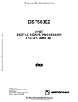
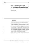
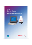
Implementation of a Serial Communication
Interface for a Signal Processor
by
Jens Eriksson
and
Kristian Nilsson
Reg nr: LiTH-ISY-EX-ET-0272-2003
2003-10-29
Implementation of a Serial Communication
Interface for a Signal Processor
Master Thesis
Division of Electronics Systems
Department of Electrical Engineering
Linköping Institute of Technology
Linköping University, Sweden
By
Jens Eriksson
and
Kristian Nilsson
Reg nr: LiTH-ISY-EX-ET-0272-2003
Supervisor:
Thomas Johansson
Ulrik Lindblad
Patrik Thalin
Examiner:
Kent Palmkvist
2003-10-29
Avdelning, Institution
Division, Department
Datum
Date
2003-10-29
Institutionen för systemteknik
581 83 LINKÖPING
Språk
Language
Svenska/Swedish
X Engelska/English
Rapporttyp
Report category
Licentiatavhandling
X Examensarbete
C-uppsats
D-uppsats
ISBN
ISRN LITH-ISY-EX-ET-0272-2003
Serietitel och serienummer
Title of series, numbering
ISSN
Övrig rapport
____
URL för elektronisk version
http://www.ep.liu.se/exjobb/isy/2003/272/
Titel
Title
Implementation of a Serial Communication Interface for a Signal Processor
Författare
Author
Jens Eriksson, Kristian Nilsson
Sammanfattning
Abstract
The purpose of this thesis was to implement a serial communication port model for a digital
signal processor. It is a behavioral model, developed using VHDL, that is instruction
comparisable to the Motorola digital signal processor DSP 56002. It supports five different data
transfer modes and provides a programmable baud rate generator.
This report starts out by giving a description of the external port, port C, the pin control logic and
general purpose functionality. Then a more detailed description of the three pin dedicated serial
communication interface is presented, the different operating modes and the baud rate generator
are described.
Nyckelord
Keyword
Serial communication, VHDL
Table of contents
1 INTRODUCTION................................................................................... 1
1.1 BACKGROUND...................................................................................... 1
1.2 TASK ................................................................................................... 2
1.3 CHAPTER DESCRIPTION......................................................................... 2
1.4 SEQUENCE OF WORK ............................................................................ 3
2 PORT C ................................................................................................... 5
3 SCI ........................................................................................................... 9
3.1 THE REGISTERS.................................................................................... 9
3.1.1 Transfer registers ......................................................................... 9
3.1.2 SCI control and status registers...................................................11
3.1.3 The SCI control register (SCR)....................................................13
3.1.4 The SCI status register (SSR).......................................................15
3.1.5 The SCI clock control register (SCCR) ........................................16
3.2 SCI STRUCTURAL DESCRIPTION ...........................................................17
3.3 BAUD RATE GENERATOR .....................................................................21
3.3.1 Behavior ......................................................................................22
3.3.2 Operation ....................................................................................22
3.4 DATA TRANSFER .................................................................................24
3.4.1 Wakeup modes.............................................................................24
3.4.2 The word modes ..........................................................................25
4 SIMULATION ...................................................................................... 31
5 DIFFERENCES BETWEEN MODEL AND ACTUAL DSP............. 35
6 PROBLEMS.......................................................................................... 37
7 USING FPGA ADVANTAGE.............................................................. 39
7.1 DESIGN ...............................................................................................39
7.2 SIMULATING .......................................................................................39
8 RESULT AND CONCEIVABLE FUTURE IMPROVEMENTS ...... 41
BIBLIOGRAPHY .................................................................................... 43
APPENDIX A, GLOSSARY...................................................................... 45
1 Introduction
1 Introduction
1.1 Background
Electronics Systems (ES), a division at the University of Linköping, is running a
project with the purpose of creating a synthesizable instruction comparisable
version of the Motorola digital signal processor DSP 56002 (figure 1). This project
can be divided into several blocks.
One of these blocks is the somewhat detached Port C, which constitutes a serial
communication interface to the surrounding world.
Figure 1 The Motorola DSP 56002
-1-
1 Introduction
1.2 Task
The purpose of this work was to implement the Port C serial communication
interface, the SCI, using VHDL. We made the restriction of creating a behavioral
model. There were given requirements on pins and names.
In addition to constructing the SCI, the task demanded the basic Port C external
interface to be implemented. This meant implementing pin control logic and
general purpose I/O functionality.
The behavior and timing of the signals was to be implemented in accordance with
the descriptions given in the user’s manual. Each mode was to be specified, coded
and validated through testing.
This report, along with all other documentation, was required to be written in
English as the material should be available to visiting scientists.
1.3 Chapter description
Chapter 2 gives a general description of port C, describing the basic external
interface and the pin control.
The majority of this report is constituted by chapter 3, which describes the
structure and behavior of the SCI. Pertinent simulation results are presented in
chapter 4.
Inevitably a behavioral model like this will diverge from the actual DSP. Known
differences are accounted for in chapter 5. Other plausible problems are accounted
for in chapter 6.
-2-
1 Introduction
In chapter 7 we mention some of our experiences using FPGA during the process
of designing and simulating.
Finally, chapter 8 presents the result of this work and future work that we see
might be done to improve the instruction comparisable model.
1.4 Sequence of work
As the purpose of this work was to implement, or redesign, an existing interface,
the first two weeks were spent studying the manual and getting acquainted with the
structure of it. This process was somewhat cumbersome as the manual does not
really convey the structural composition of the interface. Also the behavior of
certain signals is a bit unclear. This particularly applies to signals or actions that
are not limited to Port C, such as interrupts.
During this period of time we also sought guidance from similar open core projects
online, without any real success. It seems the generic language for such projects is
Verilog.
The third week was pretty much wasted in a coding attempt based on the
assumption that the best way to implement the interface was by using the HDL
Designer tools built in state machine designer. This idea was finally abandoned
because of limited flexibility.
After that a couple of weeks of intertwined coding and testing followed. We started
with designing the external Port C interface, the pin selection and the GPIO.
The next step meant implementing the serial communication interface, the SCI.
This was done using a bottom up approach. The different modes were initially
-3-
1 Introduction
coded and tested one by one. Most of the problems throughout this project came
from trying to get them to work together, simultaneously.
Finally we wrote this report, describing this work and what it has lead to.
-4-
2 Port C
2 Port C
PC0
PC1
PC2
PC3
PC4
PC5
PC6
PC7
PC8
Port C
I/O
(9)
RXD
TXD
SCLK
SC0
SC1
SC2
SCK
SRD
STD
Figure 2 Port C
Port C (figure 2) is a nine pin input/output (I/O) port. Each pin can be configured
either as a general purpose I/O (GPIO) or as a serial communication pin. Pins 0 to
2 are either GPIO or Serial communication interface (SCI). Pins 3 to 8 are either
GPIO or serial synchronous interface (SSI).
GPIO is used to implement functions that are not implemented with the dedicated
controllers in the SCI or SSI, and require simple input or output software
controlled signals.
The Port C external interface is controlled by three memory mapped registers,
mapped to the processors X-memory. These registers are:
• The Port C control register, the PCC, which determines whether a given pin
is a GPIO- or a serial communication pin.
• The Port C data direction register, the PCDDR, which determines whether a
pin is an input or an output.
• The Port C data register, the PCD, which holds the data being received or
transmitted.
-5-
2 Port C
The PCDDR and the PCD are only used for GPIO. Each bit in the PCC
corresponds to a single pin, if the bit is cleared the pin is configured as GPIO,
otherwise it is a serial communication pin. Similarly, clearing a bit in the PCDDR
means configuring the corresponding pin as an input, setting the bit to one turns the
pin into an output. GPIO means that when the pin is an input the value of the pin is
latched to the PCD. When it is an output the pin sees the value of the PCD. Upon
startup or reset all pins are configured as GPIO inputs.
PIN
PORT REGISTERS
PORT C DATA (PCD)
REGISTER BIT
(GPIO
POSITION)
DATA DIRECTION
REGISTER (PCDDR)
PORT C CONTROL
(PCC) REGISTER BIT
(INPUT
POSITION)
PERIPHERAL LOGIC
PORT INPUT DATA BIT
OUTPUT DATA BIT
DATA DIRECTION BIT
INPUT DATA BIT
Figure 3 Port C I/O Pin Control Logic
The pin control logic is depicted in figure 3. When configured as an input the
processor will get the logic level on the pin upon read. Writing to the PCD is not
possible since the buffer is in high impedance. When configured as an output the
processor will see the PCD upon read, meaning it will not see the logic level on the
pin.
-6-
2 Port C
When configured as an SCI, Port C is meant to work as a connection to other
standardized units, such as other DSPs, processors, modems and other peripherals.
-7-
2 Port C
-8-
3 SCI
3 SCI
The SCI is constituted by three pins: Receive data (RXD), transmit data (TXD)
and the SCI serial clock (SCLK). It provides a versatile connection to other units.
Communication between the SCI and the DSP core is performed with memory
mapped control and data registers. A programmable baud rate generator divides the
internal transmit and receive clocks from either the DSP clock or a clock applied
externally on the SCLK pin. During data transfer the SCI can operate in five
different word modes and two different wakeup modes.
3.1 The Registers
The registers available for controlling and communicating with the SCI are all
memory mapped. There are two control registers, the SCI control register (SCR)
and the SCI clock control register (SCCR). These are both 16-bit registers. There
is also one 8-bit status register (SSR). The purpose of each individual bit in these
registers will be described later on in this chapter (3.1.2-3.1.5). There are also two
different types of data transfer registers.
3.1.1 Transfer registers
SXhigh, SXmid and SXlow constitute one register (SX) and STXA is an address
data register. Along with these there are two non memory mapped shift registers.
The SCI receive data shift register (SRDSH) is used to shift in serial data sampled
from the RXD pin. Data is serially shifted in to SRDSH, and is then transferred in
parallel to one of the data transfer registers. During transmission data is sent from
the data transfer registers in parallel to the SCI transmit data shift register
(STDSH), from which it is then serially shifted out to the TXD pin. The
composition of these registers can be seen in figure 4.
-9-
3 SCI
(a) Receive Data Register
(b) Transmit Data Register
Figure 4 SCI Transfer Register Model
The SCI data transfer register (SX) is a 24 bit register divided into three 8 bit
registers mapped to three adjacent memory positions. The reason for mapping
them this way is so that three bytes can be “OR”ed into a 24 bit word, 24 bits is the
size of the memory bus. The actual mapping of the memory lies outside the frames
of this thesis.
- 10 -
3 SCI
3.1.2 SCI control and status registers
As mentioned before there are two control registers and a status register
comprising the core of the SCI. Each bit in these registers represents some sort of
flag or control signal, as can be seen in figure 5.
Table 1 shows the content of the registers after reset. There are two possible reset
scenarios, hardware reset (HW) and individual reset (IR). Individual reset occurs
when none of the dedicated pins are configured as SCI. Reset is active high.
Register
Bit
SCR
15 - 0
7-2
1-0
15 - 0
SSR
NOTES:
SSR[1] = TDRE
SSR[0] = TRNE
SCCR
Reset Type
HW
IR
0
0
0
1
1
0
-
HW = Hardware reset is caused by asserting the external RESET pin
IR = Individual reset is caused by clearing PCC[2-0] (configured for general-purpose I/O)
Table 1 Registers after Reset
- 11 -
3 SCI
Figure 5 SCI Control and Status Registers
- 12 -
3 SCI
3.1.3 The SCI control register (SCR)
The purpose of the SCR is to tell the SCI how to operate, it does this through
means of 16 control signals.
The word select bits (WDS)
These three bits determine in which of the five word modes to operate. (See table 2,
3.4.2)
The SCI shift direction bit (SSFTD)
Determines how data is shifted in or out, LSB or MSB first. When SSFTD is
cleared, data is shifted LSB first, when it is set, data is shifted MSB first.
Send break (SBK)
If an unusual event occurs, giving the DSP core reason to believe that data has
been distorted, a break can be sent by setting this bit.
WAKE
When the receiver is sleeping this bit determines what is required to wake it up. If
WAKE is cleared, idle line wakeup mode is chosen, if it is set, address bit wakeup
mode is chosen.
Receiver wake up enable (RWU)
Setting this bit puts the receiver to sleep. It is cleared upon wake up. This way it is
possible to use the RWU to force the receiver to sleep or wake up.
Wired-OR mode select (WOMS)
When set, the WOMS bit is supposed to protect the TXD driver while it is wired
together with other transmitters.
- 13 -
3 SCI
Receiver and Transmitter enable (RE, TE)
These bits are used to enable/disable the receiver/transmitter. TE is also used as a
preamble trigger, toggling TE will cause the transmitter to send a preamble.
Idle line interrupt enable (ILIE)
If ILIE is set, an interrupt will be requested when a start bit occurs. All interrupts
are handled by the interrupt controller, which lies outside the SCI and is yet to be
implemented.
Receive and transmit interrupt enable (RIE, TIE)
A receive data interrupt is requested when both RDRF and RIE are set. Transmit
data interrupt will be requested when both TDRE and TIE are set.
Timer interrupt enable (TMIE)
When this bit is set, the baud rate generator will request periodic interrupts at a
rate specified by the SCCR.
SCI timer interrupt rate bit (STIR)
This bit controls a divide by 32 for the interrupt rate. Setting the bit bypasses the
divide by 32.
SCI clock polarity bit (SCKP)
When SCKP is set, the polarity of the clock is shifted.
- 14 -
3 SCI
3.1.4 The SCI status register (SSR)
The SSR conveys the status of the SCI to the DSP core. The error flags in the SSR
are cleared when the DSP core reads the register.
Transmitter empty (TRNE)
This bit is set when both STDSH and the data register are empty. TRNE being set
indicates that no message is currently beeing transmitted.
Transmit data register empty (TDRE)
TDRE equals zero indicates that there is data to be sent in the data register.
Receive data register full (RDRF)
When this bit is set no data may be transferred from the SRDSH. RDRF is cleared
when the DSP reads the SX.
IDLE
The IDLE bit shows the status of the line at all times. If IDLE is cleared the
receiver is busy.
Overrun error flag (ORF)
If there is data ready to be transferred from SRDSH to SX while RDRF is set this
flag is set.
Parity error flag (PE)
In the modes using parity this flag is set when the parity bit does not match the
parity chosen.
- 15 -
3 SCI
Framing error flag (FE)
If a character is missing a stop bit (the last bit is not set) this flag goes high.
Received bit 8 address bit (R8)
If the received character is an address (the tenth bit in the word is set), while using
the multidrop mode, R8 is set.
3.1.5 The SCI clock control register (SCCR)
What bit rate and which clock to use is determined by the 16 bit SCCR.
Clock divider bits (CD11-0)
These bits constitute a number between 0 and 4096, which is the clock divider
number.
Clock out divider bit (COD)
The COD bit only affects the asynchronous modes, and only if SCLK is an output.
If COD is cleared the internal clock is divided by 16 to form the SCLK. If COD is
set the SCLK will run at the same rate as the internal clock (polarity might differ
though).
SCI clock prescaler bit (SCP)
Aside from the clock divider bits, the DSP clock is additionally divided by the
prescaler. SCP equals zero means divide by 1 and SCP equals one results in a
divide by 8.
Receive/transmit clock source mode bits (RCM/TCM)
These bits determine if the receive/transmit clocks are internal (divided from the
DSP clock) or external (from SCLK). Zero selects internal clock and one selects
external clock.
- 16 -
3 SCI
3.2 SCI structural description
The top block (figure 6):
If either of the pins is configured as SCI, the SCI_data vector is updated on every
clock edge, bringing the data to the SCI block. The Port C I/O block handles the
pin selection and GPIO functionality. If either of the pins are configured as SCI,
the SCI is released from reset.
The first SCI sublevel (figure 7):
This level includes three blocks: The Namedef block, in which the register vectors
are divided into separate internal signals. The baudrate generator, which
determines timing and polarization of clocks. The SCI_states block, which
contains another sublevel.
Since the registers for controlling and comunicating with the SCI are memory
mapped, and the SCI can not occupy the memory bus at all time, it was necessary
to create internal signals so that data is not lost. This is done in the Namedef block.
The first sublevel of the SCI, including the Namedef block, is depicted in figure 6.
The name Namedef comes from the fact that the individual register bits are each
given a separate internal signal, conveniently named as its corresponding bit. This
also simplifies handling the signals in the code as it means not having to access
them by indexing vectors. The downside of this procedure is that it introduces a
delay of up to one DSP clock.
The SCI_states (figure 8) sublevel:
The SCI can operate in five different word modes. Each block in this sublevel
handles one of those modes.
- 17 -
3 SCI
Figure 6 The Top block structure
- 18 -
3 SCI
Figure 7 The SCI sublevel block structure
- 19 -
3 SCI
Figure 8 The SCI states block structure
- 20 -
3 SCI
3.3 Baud rate generator
The baud rate generator block (see figure 9) handles the timing and generation of
the clocks. It is controlled by the 16 bit SCCR (figure 5).
fOSC
DIVIDE
BY 2
12-BIT COUNTER
CD11 – CD0
PRESCALER:
DIVIDE BY
1 OR 8
DIVIDE
BY 2
SCP
INTERNAL CLOCK
DIVIDE
BY 16
SCI CORE LOGIC :
USES DIVIDE BY 16 FOR
ASYNCHRONOUS
USES DIVIDE BY 2 FOR
SYNCHRONOUS
STIR
TIMER INTERRUPT
(STMINT)
COD
f OSC
8 * (7( SCP) + 1) * CD + 1
f OSC
BPSASYNC =
64 * (7( SCP ) + 1) * CD + 1
IF ASYNCHRONOUS
DIVIDE BY 1 OR 16
IF SYNCHRONOUS
DIVIDE BY 2
BPSSYNC =
SCKP = 0
SCKP
where: SCP = 0 or 1
CD = 0 to $FFF
SCKP = 0
→+
→ -
TO SCLK
Figure 9 SCI Baud Rate Generator
The internal clock, which is generated in this block, determines the baud rate, i.e.
the data transmission speed. The baud rate is decided by the processor oscillator
frequency (DSP clock) and the configuration of the time base. The time base is
determined by the control bits in the SCCR.
In addition to producing the clocks, the baud rate block can also be used to create a
periodic interrupt.
- 21 -
3 SCI
3.3.1 Behavior
Figure 9 shows the behavior of the baud rate generator. The SCI internal clock is
divided from the DSP clock in accordance with the configuration of the SCCR.
The DSP clock is scaled by 2 before it is divided by the clock divider number
(CD11-CD0). It is then further divided by 1 or 8 (SCP equals zero or one). This
output is further divided by 2 to form the internal clock. It can also be used as the
interrupt rate for periodic interrupts. When STIR is set this output is divided by 32
before forming the interrupt rate. The internal clock is divided by 1 or 16, if the
mode is asynchronous, or by 2, if the mode is synchronous, to form the SLCK
output. If SCKP is set the polarity of SCLK is inverted.
In total 3 clocks are generated by the baud rate generator:
• The internal clock
• The SCLK
• The interrupt clock.
The SCI core uses the internal clock divided by 16 for the asynchronous modes,
and divided by 2 for the synchronous mode. Hence if an external clock is to be
used a 16-times clock must be applied to the SCLK pin.
The SCI receiver and transmitter use separate receive- and transmit clocks that are
not necessarily the same (depending on RCM and TCM). The assignments of these
clocks are done internally in the SCI states block. The only clocks transmitted from
the baud rate block are SCI clock and the internal clock.
3.3.2 Operation
The three different clocks are divided with the help of three denominator variables.
These denominators (integer values) are calculated by successively stepping
through the bits in the SCCR as well as pertinent bits in the SCR. Each
- 22 -
3 SCI
denominator initially gets the value of the clock divider bits multiplied by 2. If then
e.g. SCP is set, that value is simply multiplied by 8. The value of the clock divider
bits is not directly accessible, it has to be transformed into an integer value. This is
done by the LogicVector2int function.
The denominators are then used to control three different counters, clocked by the
DSP clock. When the counter reaches the value of the denominator the clock shifts.
The interrupt clock however is not an actual clock, rather a periodic timer
(interrupts are to be requested at the rate set by the timer). At the rate set by the
interrupt denominator a flag, STMINT, is set. When STMINT and TMIE are both
set a timer interrupt will be requested. This flag then has to be cleared by the
interrupt controller to avoid that the request is sent again.
The bit rate for the synchronous mode is given by the following equation:
BPS SYNC =
DSPclk
8 * (7 * SCP + 1) * CD + 1
The bit rate for the asynchronous mode is given by the following equation:
BPS ASYNC =
DSPclk
64 * (7 * SCP + 1) * CD + 1
- 23 -
3 SCI
3.4 Data transfer
In both the synchronous and the asynchronous modes, messages are transferred
byte by byte. This is the only possibility since the shift registers are only one byte
wide.
In the synchronous mode there is no idle line in between messages, nor any start or
stop bits separating characters. Data is simply shifted whenever a clock is applied.
The purpose of the synchronous mode is for the SCI to function as a fast serial to
parallel- or parallel to serial converter.
3.4.1 Wakeup modes
All asynchronous modes can operate in either idle line wake up mode or address
bit wake up mode.
3.4.1.1 Idle line wakeup
In the idle line wake up mode messages are separated by a preamble or a break,
and bytes are separated by start and stop bits. The receiver wakes up when it
detects an idle line (full word frame of ones detected). As long as no transmission
is in progress the line is idle (all ones).
A preamble turns the line idle and must be sent before transmitting a message in
idle line wake up mode. A break can be used by the DSP in order to force a
framing error, thus signaling an unusual event.
The RXD pin is constantly sampled at 16 times the data rate (see baud rate section)
to find the start bit (the transition from idle to zero). Then the byte is clocked in to
the SRDSH. Messages are to be separated either by a preamble (full word frame of
ones) or a break (full word frame of zeros).
- 24 -
3 SCI
To send data in idle line wake up mode, TE must be toggled to turn the line idle
(preamble the line), then the message can be sent.
3.4.1.2 Address bit wake up
In the address bit wakeup mode there is no need for an idle line in between
messages. Instead the receiver wakes up if the eighth or ninth bit (depending on the
word mode) is set, marking it as an address. This eliminates the dead time in
between messages.
When operating in the address bit wake up mode, the receiver is constantly shifting
data in to SRDSH, but only wakes up if it detects an address byte. When that has
happened the same procedure as for the idle line mode is carried out.
3.4.2 The word modes
SCI reception and transmission can be performed in five different word modes.
There is one synchronous and four asynchronous modes (Table 2).
WDS2 WDS1 WDS0
0
0
0
0
0
1
0
1
0
0
1
1
1
0
0
1
0
1
1
1
0
1
1
1
Word Formats
8-bits Synchronous Data (shift register mode)
Reserved
10-bit Asynchronous (1 start, 8 data, 1 stop)
Reserved
11-bit Asynchronous (1 start, 8 data, 1 even parity, 1 stop)
11-bit Asynchronous (1 start, 8 data, 1 odd parity, 1 stop)
11-bit Multidrop (1 start, 8 data, 1 data type, 1 stop)
Reserved
Table 2 Word Formats
- 25 -
3 SCI
3.4.2.1 8-bit synchronous data
In this mode the SCI functions as a high speed shift register used for parallel to
serial or serial to parallel conversion.
There are no error flags present in this mode, nor any start or stop bits. This
implicates that loss of data or invalid data can not be detected.
3.4.2.2 10-bit asynchronous data
Data is transferred using 1 start bit, 8 data bits and 1 stop bit. The start bit is zero
and the stop bit should be one. Data is clocked on the rising edge of the receive
clock (see the baud rate generator section for clocks). Depending on SSFTD, data
is shifted in either LSB or MSB first.
Reception
Firstly for the receiver to initiate it is necessary for the line to go idle. When 10
consecutive ones have been detected the IDLE flag is set. Detection of an idle line
clears the RWU and wakes up the receiver. The IDLE flag is cleared as soon as a
start bit is detected, indicating that the receiver is busy.
Upon detection of a start bit (the transition from idle line to zero) the receiver
clocks 8 data bits into SRDSH. It then shifts them to the data register and sets the
RDRF flag. Depending on the position of the bytecntr pointer (an internal signal)
data is latched to either SXhigh, SXmid or SXlow. If the stop bit is zero, a framing
error has occurred and the FE flag is set.
When the DSP core reads the data register it also clears the RDRF, clearing the
way for another byte to be received. If the receiver tries to write to the data register
while RDRF is set, an overrun error has occurred and the ORF flag is set.
- 26 -
3 SCI
Transmission
The transmitter is activated when a rising edge on TE is detected. This sets the
transmitteractive help variable and also clears the preambled variable. Clearing
preambled serves two purposes. Firstly it insures that the first thing to happen upon
activation is a preambling of the line. Also it will cause a TE-toggle to execute a
preamble.
Data is transmitted on the falling edge of the transmit clock and what happens is
determined by a priority list:
1. If preambled equals zero the line is preambled, meaning it will send 10
consecutive ones (a full word frame).
2. If SBK is set a break will be sent, meaning 10 consecutive zeros will be
transmitted.
3. The character (byte) will be transmitted.
When a character is to be transmitted, TDRE is polled to see if there is valid data
in the data register. If so the data will be latched into the STDSH from the data
register pointed out by bytecntr. TDRE goes high while the second bit of the
character is being shifted out to the TXD pin.
When the whole byte has been shifted out, the transmitter sends an additional one
(stop bit). While sending the stop bit TE is polled, and if it is zero the
transmitteractive variable is cleared and the transmitter is deactivated. This way the
transmission of the current byte will be completed whenever TE is cleared. If TE is
set, and no preamble or break is pending, the next byte will be sent.
- 27 -
3 SCI
3.4.2.3 11-bit asynchronous even/odd parity data
Data is transferred using 1 start bit, 8 data bits, 1 parity bit and 1 stop bit. The two
modes are the same except for the difference in parity. SSFTD does not affect the
position of the parity bit, it is always the tenth bit.
Reception
Aside from the parity check and the frame size being 11 bits, these modes work
very much like the 10 bit mode. The parity check is made by simply introducing a
variable that counts the number of ones. If the parity bit does not match then the
PE flag is set.
Transmission
Again very much like the ten bit mode. The exception being that prior to sending
the tenth bit (the parity bit) a loop counts the number of ones in STDSH. It then
sets the bit according to the parity chosen.
3.4.2.4 Multidrop
Data is transferred using 1 start bit, 8 data bits, 1 data type bit and 1 stop bit. The
data type bit tells whether the character is a data byte (the bit is cleared) or if it is
an address byte (the bit is set).
The purpose of the multidrop mode is to allow for multiple receivers and
transmitters to be connected together on a single line network.
Reception
When operating in idle line wake up mode the first byte to be received after wake
up should be an address byte, if it is, the R8 bit will be set and the DSP determines
whether or not the message is meant for it. If so, the remainder of the message will
- 28 -
3 SCI
be retrieved. If not, the receiver will simply go to sleep waiting for a reason,
determined by the WAKE bit, to wake up.
When operating in the address bit wake up mode the receiver is constantly shifting
data into the SRDSH, but only wakes up if the ninth bit is set, indicating that it is
an address byte. When that has happened the same procedure as that of the idle line
mode follows.
Transmission
Transmission always begins by sending an address. The DSP stores the address
byte in the STXA. This automatically sets the data type bit to one, indicating that it
is an address. Bytes stored in either of the SX registers are in a similar fashion
automatically turned into data bytes.
- 29 -
3 SCI
- 30 -
4 Simulation
4 Simulation
In order to validate that the different blocks behaved as they were intended to,
various test scenarios were simulated using the program ModelSim.
During data transfer certain flags have to be controlled by the DSP, such as RDRF
and TRNE. In simulation these signals are set in the test files as they should be by
the DSP in actuality. Pertinent simulation results are presented below.
Figure 10 Simulation results of the Asynchronous clock
Figure 10 illustrates a simulation performed on the baud rate generator block. The
clock polarity is shifted, the internal SCLK is the actual SCLK pin inverted. The
mode is asynchronous and the divider is set to 3.
Figure 11 Simulation results of the Synchronous clock
Figure 11 illustrates another simulation performed on the baud rate generator
block, this time in the Synchronous mode with the divider set to 3. Clock polarity
- 31 -
4 Simulation
is unshifted. These tests show that the synchronous mode runs at a faster pace than
the asynchronous (eight times faster, for a given time base).
Figure 12 Simulation results of the 11-bit Asynchronous odd parity
Figure 12 conveys a simulation performed from the SCI block, configured to
operate in the 11 bit asynchronous odd parity mode. Receiving three bytes and then
sending three bytes, LSB first, in idle line wake up mode. After the line has gone
idle and the start bit is detected, the RWU is cleared and reception commences.
The first character received has an intentional parity error to validate the operation
of the parity error flag. The second character received has an intentionally corrupt
stop bit to validate the operation of the framing error flag.
The high impedance state (Z) of the R8 bit in the SSR is due to the fact that R8 is
not used in this mode. As can be seen, the initial signal levels of the shift and data
registers are high impedance.
- 32 -
4 Simulation
Figure 13 Simulation results of the Port C, 11-bit Asynchronous odd parity
In figure 13 the same simulation is run from the external Port C block. The only
difference is that this time the TXD pin (pc1) is used as a GPIO input when it is
not used by the SCI. The datadirection vector determines how the SCI uses the pins
(pc2, pc1, pc0), and has nothing to do with GPIO direction.
Figure 14 Delay caused by the Namedef block
Figure 14 illustrates the delay introduced by the Namedef block. The internal RXD
signal is not updated with the current value of SCI_indata(0) until the next DSP
clock edge.
- 33 -
4 Simulation
- 34 -
5 Differences between model and actual DSP
5 Differences between model and actual DSP
In some aspects, or events, this model deviates from the behavior of the actual
DSP.
Due to the restriction of a behavioral model, the functionality of the WOMS bit is
yet to be implemented, thus rendering it as a don’t care. The reason for this is that
it simply is not a feasible functionality to implement in a behavioral model. This
means that it might be unwise to connect this version to a line with multiple
transmitters, as no precautions have been taken to protect the transmitter.
The data transfer register comprised of SXhigh, SXmid and SXlow also differs
from the description in the manual. For some reason the manual divides this
register into a receive (SRX) and a transmit (STX) register. However they are
mapped to the same memory address, hence they are the same. Therefore the
register is simply called SX in the clone.
The manual claims that the maximum bit rate is the DSP clock divided by 2.
However, following the description of the baud rate generator renders a maximum
bit rate of DSP clock divided by 4, which is the case for this model.
Separating the registers into internal signals in the NameDef block introduces a
delay of up to one DSP clock. This should not be a problem though since the
signals are only delayed until the next DSP clock edge, and nothing happens
outside of clock edges during data transfer. Also all of the signals are assigned
simultaneously, this is of course possible, but the individual registers can not be
read simultaneously as they occupy different memory positions in the actual DSP.
This means that the registers will have to be buffered between the memory bus and
the NameDef block.
- 35 -
5 Differences between model and actual DSP
One possible problem spawns from the fact that a write command (wr equals one)
causes all internal signals to be updated, which might not always be desirable.
The SSI would have made this work too extensive, hence it has not been
implemented.
- 36 -
6 Problems
6 Problems
Working as a part of a larger project caused some confusion about the extent of the
SCI. The SCI is a somewhat detached part of the DSP. However not all of the
events described in the manual section about the SCI are actually handled by the
SCI. For example all interrupts requested. They are supposed to call a specific
routine, but that is handled by the interrupt controller. The decision whether to
accept a message in the multidrop mode is made outside the SCI. The conditions
reported by the status register are attended to by the DSP core. These are all things
that took some time to conclude.
Another problem was getting the different blocks to work in coherence, when
simulated from the outside. The blocks that are not in use were interfering with the
signals. This caused the signal levels to go undefined. The undefined signals were
caused by multiple drivers for the same signals. The solution was to force these
signals to high impedance, tri-state, by setting them to ‘Z’, when they should not
drive the signals. This sounds simple enough, but it turned out to be quite
cumbersome. Cumbersome because care had to be taken not only to which mode is
active, but also to the setting of the read and write signals, as well as RE and TE.
The SCI core uses the internal clock or the SCLK divided by 2 for asynchronous
and divided by 16 for synchronous modes. This is fine as long as the internal clock
is being used and the SCLK is an output, because then the SCI core clock runs at
the same pace as the SCLK. However when the SCI core clock is divided from the
SCLK pin, they run at different frequencies, which would seem undesirable. This
causes data to be shifted either every 2 (synchronous) or every 16 (asynchronous)
SCLK clock cycles. Whatever type of unit is applying the SCLK would probably
expect data to be updated on every clock cycle.
- 37 -
6 Problems
- 38 -
7 Using FPGA advantage
7 Using FPGA Advantage
All the design and simulation in this project was performed using FPGA
Advantage.
7.1 Design
A designer tool that uses a graphical user interface facilitates structuring a project
into different blocks. It does so because the wiring to and from the blocks does not
need to be coded by hand.
At times though, the GUI can be quite vexing. This particularly applies while
attempting to rearrange signals, whether it be wiring or type, where the GUI seems
to be reluctant to change the signal order.
7.2 Simulating
The blocks can be simulated individually using ModelSim. This was essential for
this task, as when trying to get everything to work together alterations were made
constantly. This meant that actions had to be taken to ensure the modes were still
working individually.
Assigning, or forcing, the signal values in ModelSim can be done either by typing
force – signal name – value, on the command line, or by selecting the signal from
the signals window and then choosing force. This is quite confusing as the default
force method differs. While using the command line the default force method is
deposit. While forcing from the signals window the default method is freeze.
Forcing a freeze means that the signal is frozen to the assigned value and cannot be
altered by the simulation. This is something that in this case was undesirable and
thus caused some perplexity.
- 39 -
7 Using FPGA advantage
One very positive thing with the simulator is that all commands, whether typed in
or entered using GUI, are saved in the command window. This enables collecting
all commands in an executable macro, a .DO file, which makes repeated testing
very convenient.
One problem with the simulator occurs while using break points to step through the
code in order to determine what is wrong. It seems that sometimes the mere
presence of break points affect the simulation result, thus ruining any chance of
detecting the problem this way.
- 40 -
8 Result and conceivable future improvements
8 Result and conceivable future improvements
The result of this work is an instruction comparisable model that behaves as
intended in simulation. The layout feels well structured and easy to comprehend.
Although in some points the model diverges from the Motorola DSP56002 and in
some points, such as with the clocks, things are a bit unclear.
In order to make any actual use of this model it has to be connected to the rest of
the processor. Doing so requires some additional work with mapping the registers
to the memory. For the Port C to be complete implementing the SSI would also be
required.
Another plausible improvement would be to transform this behavioral model into a
more hardware oriented one.
- 41 -
8 Result and conceivable future improvements
- 42 -
Bibliography
Bibliography
Skahill, Kevin (1996) VHDL for programmable logic, Menlo Park : AddisonWesley Publishing Company, Inc. ISBN 0-201-89573-0
DSP56002 24 bit digital signal processor User’s manual, West Austin : Motorola,
Inc.
OPENCORES.ORG. (12 May 2002).
Retrieved May 26, 2003 from the World Wide Web:
http://www.opencores.org/cvsweb.shtml/MiniUART/
- 43 -
Bibliography
- 44 -
Appendix A, glossary
Appendix A, glossary
Designations
Break
Full word frame of zeros
DSP
Digital signal processor
ES
Electronics systems
Idle line The line is ready, waiting for a start bit (transition from one to
zero)
Preamble Full word frame of ones
SCI
Serial communication interface
SSI
Serial synchronous interface
GPIO
General purpose input/output
VHDL
Very high definition language
LSB
Least significant bit
MSB
Most significant bit
BPS
Bits per second
GUI
Graphical user interface
FPGA
Field programmable gate array
PINS
RXD
TXD
SCLK
Receive pin
Transmit pin
SCI clock pin
Transfer registers
SX
SCI data transfer register
SRDSH SCI receive data shift register
STDSH SCI transmit data shift register
STXA
SCI address register
SCR
SCKP
STIR
TMIE
TIE
RIE
ILIE
SCI control register
SCI clock polarity
Timer interrupt rate
Timer interrupt enable
Transmit interrupt enable
Receive interrupt enable
Idle line interrupt enable
- 45 -
Appendix A, glossary
TE
RE
WOMS
RWU
WAKE
SBK
SSFTD
WDS
Transmitter enable
Receiver enable
Wired-Or mode select
Receiver wake up enable
Wake up mode select
Send break
SCI shift direction
Word select bits
SSR
R8
FE
PE
OR
IDLE
RDRF
TDRE
TRNE
SCI status register
Received bit 8
Framing error flag
Parity error flag
Overrun error flag
Idle line flag
Receive data register full
Transmit data register empty
Transmitter empty
SCCR
TCM
RCM
SCP
COD
CD
SCI clock control register
Transmit clock source bit
Receive clock source bit
SCI clock prescaler
Clock out divider
Clock divider bits
- 46 -
På svenska
Detta dokument hålls tillgängligt på Internet – eller dess framtida
ersättare – under en längre tid från publiceringsdatum under förutsättning
att inga extra-ordinära omständigheter uppstår.
Tillgång till dokumentet innebär tillstånd för var och en att läsa, ladda
ner, skriva ut enstaka kopior för enskilt bruk och att använda det
oförändrat för ickekommersiell forskning och för undervisning.
Överföring av upphovsrätten vid en senare tidpunkt kan inte upphäva
detta tillstånd. All annan användning av dokumentet kräver
upphovsmannens medgivande. För att garantera äktheten, säkerheten och
tillgängligheten finns det lösningar av teknisk och administrativ art.
Upphovsmannens ideella rätt innefattar rätt att bli nämnd som
upphovsman i den omfattning som god sed kräver vid användning av
dokumentet på ovan beskrivna sätt samt skydd mot att dokumentet ändras
eller presenteras i sådan form eller i sådant sammanhang som är
kränkande för upphovsmannens litterära eller konstnärliga anseende eller
egenart.
För ytterligare information om Linköping University Electronic Press se
förlagets hemsida: http://www.ep.liu.se/
In English
The publishers will keep this document online on the Internet - or its
possible replacement - for a considerable time from the date of
publication barring exceptional circumstances.
The online availability of the document implies a permanent
permission for anyone to read, to download, to print out single copies for
your own use and to use it unchanged for any non-commercial research
and educational purpose. Subsequent transfers of copyright cannot revoke
this permission. All other uses of the document are conditional on the
consent of the copyright owner. The publisher has taken technical and
administrative measures to assure authenticity, security and accessibility.
According to intellectual property law the author has the right to be
mentioned when his/her work is accessed as described above and to be
protected against infringement.
For additional information about the Linköping University Electronic
Press and its procedures for publication and for assurance of document
integrity, please refer to its WWW home page: http://www.ep.liu.se
© [Jens Eriksson, Kristian Nilsson]