1
Wizcon for Windows and
Internet
User’s Guide
Version 7.5
Warranty/Trademarks
This document is for information only and is subject to change without
prior notice. It does not represent a commitment on the part of PC Soft
International Ltd. No part of this document may be reproduced or
transmitted in any form or by any means, electronic or mechanical,
including photocopying or recording, for any purpose, without written
permission from PC Soft International Ltd.
If you find any problems in the documentation, please report them in
writing. PC Soft does not warrant that this documentation is error-free.
© Copyright 1997, 1998, 1999 by PC Soft International Ltd.
Wizcon is a trademark of PC Soft International Ltd. Windows 95,
Windows NT are registered trademarks of Microsoft Corporation.
All other products and brand names are trademarks of their respective
companies.
WIZF\WIZUGE\7.5\0499
Table of Contents
Chapter 1 Using this Guide ........................................................... 1-1
About this Manual................................................................................................... 1-2
What You Should Know ......................................................................................... 1-6
Typographical Convention .................................................................................... 1-6
Registering Your Product ...................................................................................... 1-7
Receiving Technical Support ................................................................................ 1-7
Chapter 2 Introducing Wizcon....................................................... 2-1
What is Wizcon for Windows and Internet? ......................................................... 2-2
Typical Wizcon SCADA Configuration.................................................................. 2-3
Wizcon for Windows and Internet Main Features ............................................... 2-4
Alarm Processing.................................................................................................. 2-4
Automatic Network Optimization........................................................................... 2-4
Background Processing ........................................................................................ 2-5
Built-in Report Generator ...................................................................................... 2-6
Charts and Reports............................................................................................... 2-6
Database Connectivity .......................................................................................... 2-6
Easy Maintenance ................................................................................................ 2-7
Events Summary................................................................................................... 2-7
Events Summary Profiles ..................................................................................... 2-8
Events Summary Viewer....................................................................................... 2-8
Hot Backup Support.............................................................................................. 2-8
Innovative Graphics Presentation......................................................................... 2-8
Millisecond Time Stamping ................................................................................... 2-9
Networking .......................................................................................................... 2-10
Online Design ..................................................................................................... 2-10
Open Architecture ............................................................................................... 2-10
Picture Viewer..................................................................................................... 2-11
PLCs Sampler..................................................................................................... 2-11
Recipes ............................................................................................................... 2-12
Table of Contents i
Security on the Web ........................................................................................... 2-12
Tags .................................................................................................................... 2-12
Trend Profiles ..................................................................................................... 2-13
Trend Viewer....................................................................................................... 2-13
Wizcon Language ............................................................................................... 2-14
Year 2000 Compatibility...................................................................................... 2-14
Chapter 3 Installing Wizcon for Windows and Internet ............... 3-1
System Requirements ............................................................................................ 3-2
Installation ............................................................................................................... 3-4
Uninstalling Wizcon for Windows and Internet ..................................................... 3-9
Starting Wizcon for Windows and Internet ........................................................ 3-10
Chapter 4 Getting Started .............................................................. 4-1
Accessing Wizcon .................................................................................................. 4-2
Opening Wizcon ................................................................................................... 4-2
Quick Access Bar ................................................................................................. 4-3
Designing an Application....................................................................................... 4-5
Before Designing Your Application ....................................................................... 4-5
Typical Application Requirements......................................................................... 4-6
Wizcon Workflow .................................................................................................... 4-9
Step 1: Defining Communication Drivers and Blocks ......................................... 4-10
Step 2: Defining User Groups............................................................................. 4-11
Step 3: Defining Tags and Alarms ...................................................................... 4-11
Step 4: Building the Application Image ............................................................... 4-12
Step 5: Defining Wizcon Language .................................................................... 4-13
Step 6: Testing the Application ........................................................................... 4-14
Step 7: Defining Charts, Reports and Recipes ................................................... 4-14
Step 8: Fine-Tuning the Application.................................................................... 4-16
Shutting Down ...................................................................................................... 4-17
Logout ................................................................................................................. 4-17
Exiting Wizcon .................................................................................................... 4-17
ii Wizcon for Windows and Internet User’s Guide
Chapter 5 Getting to Know the Application Studio ..................... 5-1
Overview .................................................................................................................. 5-3
All Containers Section........................................................................................... 5-7
The Control Panel ............................................................................................... 5-11
Menu Options ........................................................................................................ 5-12
Optimizing Application Performance.................................................................. 5-15
Setting General Station Parameters ................................................................... 5-16
Selecting a Default User ..................................................................................... 5-17
Setting the Date Format...................................................................................... 5-18
Setting a Format for History Files ....................................................................... 5-20
Application Setup ................................................................................................. 5-22
Defining System Options ..................................................................................... 5-26
WizPro Options ................................................................................................... 5-26
Changing Default File Paths ............................................................................... 5-29
Specifying Active Printers ................................................................................... 5-30
Operator Access Authorization........................................................................... 5-32
Operator Registration.......................................................................................... 5-34
Assigning Group Names ..................................................................................... 5-37
Menu Access Authorization ................................................................................ 5-38
MultiLanguage Support........................................................................................ 5-41
Defining MultiLanguage Support......................................................................... 5-42
Selecting a Language ......................................................................................... 5-45
Loading Wizcon Files Created in Another Wizcon Application ........................... 5-46
Layouts .................................................................................................................. 5-47
Capturing and Saving Layouts............................................................................ 5-47
Assigning Layouts to Users ................................................................................ 5-48
Loading a Layout................................................................................................. 5-49
Closing all Open Windows .................................................................................. 5-49
Saving Layouts (by Default)................................................................................ 5-50
Using the New Wizcon Application Wizard ........................................................ 5-51
Table of Contents iii
Chapter 6 Communication Drivers................................................ 6-1
Overview .................................................................................................................. 6-2
Defining Communication Drivers.......................................................................... 6-3
Communication Driver Properties ........................................................................ 6-5
Defining General Driver Properties....................................................................... 6-6
Defining Serial Port Parameters ........................................................................... 6-7
Defining Communication Blocks ........................................................................... 6-8
Viewing Driver Information.................................................................................. 6-12
Defining OPC (Wizcon Client) ............................................................................. 6-13
OPC Driver Properties.......................................................................................... 6-13
Chapter 7 Tags................................................................................ 7-1
Overview .................................................................................................................. 7-2
Basic Principles..................................................................................................... 7-2
Tag Icons .............................................................................................................. 7-3
Defining Tags .......................................................................................................... 7-4
Adding a Tag......................................................................................................... 7-5
Recording Tag Value Changes........................................................................... 7-16
Communicating Online with Other Applications.................................................. 7-17
Deleting and Modifying Tags .............................................................................. 7-20
Single Tag Input .................................................................................................... 7-21
MultiAdd Tags ....................................................................................................... 7-23
Exporting Tags...................................................................................................... 7-26
GLS File Format ................................................................................................. 7-27
Importing Tags ...................................................................................................... 7-29
Defining Tag Properties ....................................................................................... 7-31
Chapter 8 Alarms............................................................................ 8-1
Overview .................................................................................................................. 8-2
Basic Principles ...................................................................................................... 8-3
iv Wizcon for Windows and Internet User’s Guide
Defining Alarms ...................................................................................................... 8-4
General Alarm Definitions ..................................................................................... 8-5
Defining Action on Alarm .................................................................................... 8-11
Assigning Names to Alarm Classes.................................................................... 8-13
Alarm Properties ................................................................................................... 8-14
Specifying a Login/Logout Message................................................................... 8-15
Determining a Time Format ................................................................................ 8-16
Alarm Print Modes .............................................................................................. 8-17
Exporting Alarms .................................................................................................. 8-18
ALS File Format .................................................................................................. 8-21
Importing Alarms .................................................................................................. 8-23
Alarm Help Files.................................................................................................... 8-25
Chapter 9 Events Summaries ........................................................ 9-1
Overview .................................................................................................................. 9-2
Defining and Modifying Events Summaries......................................................... 9-3
Exiting the Events Summary................................................................................. 9-4
Alarm Display........................................................................................................ 9-4
Display Options....................................................................................................... 9-7
Alarm Filter............................................................................................................ 9-8
Alarm Sorting ...................................................................................................... 9-10
Alarm Display Setup ........................................................................................... 9-11
Alarm Colors ....................................................................................................... 9-13
History/Online Mode ........................................................................................... 9-15
Events Summary Operations............................................................................... 9-20
Assist .................................................................................................................. 9-21
Alarm Acknowledge ............................................................................................ 9-22
Total Acknowledge.............................................................................................. 9-22
End Alarm ........................................................................................................... 9-23
Operator-Initiated Messages .............................................................................. 9-23
Popup Events Summary ...................................................................................... 9-25
Designing Popup Events Summaries ................................................................. 9-27
Events Summary Properties................................................................................ 9-32
Events Summary Tuning Parameters................................................................. 9-32
Defining Events Summary Window Attributes .................................................... 9-34
Table of Contents v
Chapter 10 Creating Events Summary Profiles ......................... 10-1
Overview ................................................................................................................ 10-2
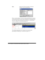
Events Summary Profile ..................................................................................... 10-2
Events Summary Viewer..................................................................................... 10-2
Interacting with the Events Summary Viewer ..................................................... 10-2
Defining and Modifying Events Summary Profiles ........................................... 10-5
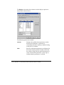
Filtering Alarms ................................................................................................... 10-6
Defining Alarm Display........................................................................................ 10-7
Enabling/Disabling Features............................................................................. 10-10
Assigning Alarm Text and Background Colors ................................................. 10-11
Creating Events Summary Viewers .................................................................. 10-13
Changing the Default Location of Events Summary Profile Files ................. 10-16
Chapter 11 Creating Images and Picture Viewers ..................... 11-1
Overview ................................................................................................................ 11-2
Picture Viewers ................................................................................................... 11-2
The Image Window ............................................................................................... 11-3
The Image Toolbar and Toolboxes..................................................................... 11-5
Window Modes ................................................................................................... 11-6
Layers .................................................................................................................... 11-9
Layer Definition ................................................................................................. 11-10
Active Layer ...................................................................................................... 11-13
Forced Layer Display........................................................................................ 11-14
Forced Layer Hide ............................................................................................ 11-15
Elaborate On Mode........................................................................................... 11-16
Moving Objects to Active Layer ........................................................................ 11-16
Viewing ................................................................................................................ 11-17
Scrolling and Panning....................................................................................... 11-17
Zooming ............................................................................................................ 11-17
Navigating ......................................................................................................... 11-20
Defining Zones.................................................................................................. 11-21
Jumping to Zones ............................................................................................. 11-23
Jumping to Positions......................................................................................... 11-24
Creating Picture Viewers ................................................................................... 11-25
vi Wizcon for Windows and Internet User’s Guide
Image Technical Specifications ........................................................................ 11-28
Standard Graphics Files (JPG and BMP) Support ........................................... 11-29
Image Properties................................................................................................. 11-30
Determining the Location of the Picture Files Folder........................................ 11-31
Repainting the Image........................................................................................ 11-32
Setting the Amount of Memory Available for Image Objects ............................ 11-36
Defining Parameters for Trigger Objects .......................................................... 11-38
Determining the Image Update Performance and the Size of the Internal Message
Buffer ................................................................................................................ 11-40
Determining the Period of Time for Slow Zones ............................................... 11-41
Determining the Blinking Rate Values for Dynamic Objects............................. 11-43
Chapter 12 Image Editor .............................................................. 12-1
Overview ................................................................................................................ 12-3
Basic Principles .................................................................................................... 12-4
Objects................................................................................................................ 12-4
Drawing Space.................................................................................................... 12-5
Image Window .................................................................................................... 12-5
Zoom Level ......................................................................................................... 12-5
Layers ................................................................................................................. 12-5
Zones .................................................................................................................. 12-6
Editor Operations ................................................................................................ 12-6
Image Toolbar and Toolboxes............................................................................. 12-7
Toolbar................................................................................................................ 12-7
Color Toolbox...................................................................................................... 12-8
Patterns Toolbox................................................................................................. 12-8
Drawing Toolbox ................................................................................................. 12-9
Align Toolbox .................................................................................................... 12-10
Operations Toolbox .......................................................................................... 12-10
Objects Toolbox ................................................................................................ 12-11
Font Bar ............................................................................................................ 12-11
Wizcon Color Features ....................................................................................... 12-12
Full Color Support ............................................................................................. 12-12
Selecting Colors................................................................................................ 12-12
Setting the Image Background Color................................................................ 12-13
Get and Save Color Options............................................................................. 12-13
Pick Color Tool ................................................................................................. 12-14
Table of Contents vii
Image Design ...................................................................................................... 12-15
Active Layer ...................................................................................................... 12-15
Mouse Buttons .................................................................................................. 12-15
Cursor ............................................................................................................... 12-15
Filling................................................................................................................. 12-16
Orientation ........................................................................................................ 12-16
Attributes........................................................................................................... 12-16
Continuous Design............................................................................................ 12-16
Multiple Windows .............................................................................................. 12-16
Design Procedure ............................................................................................. 12-17
Drawing in the Image.......................................................................................... 12-18
Object Selection/Deselecting............................................................................ 12-18
Aligning Objects ................................................................................................ 12-19
Moving/Scaling.................................................................................................. 12-20
Object Sensitive Menus .................................................................................... 12-20
Image Edit Menu ................................................................................................. 12-21
Drawing Shapes .................................................................................................. 12-22
Drawing Lines and Segmented Shapes ........................................................... 12-22
Drawing Rectangles and Ellipses ..................................................................... 12-24
Drawing Arcs..................................................................................................... 12-25
Drawing Pipes................................................................................................... 12-27
Text ................................................................................................................... 12-28
Font Style Selection ........................................................................................... 12-29
Modifying Text................................................................................................... 12-31
Image Editing ...................................................................................................... 12-32
Selection ........................................................................................................... 12-33
Deselecting ....................................................................................................... 12-34
Copying Objects................................................................................................ 12-34
Moving and Scaling Objects ............................................................................. 12-35
Undo/Redo........................................................................................................ 12-36
Find\Find Next in Image.................................................................................... 12-38
Notification Message ........................................................................................ 12-41
Modification....................................................................................................... 12-41
Bring to Front .................................................................................................... 12-42
Send to Back .................................................................................................... 12-42
Aligning Objects ................................................................................................ 12-43
Transformation.................................................................................................. 12-45
viii Wizcon for Windows and Internet User’s Guide
Clipboard Operations ......................................................................................... 12-49
Grouped Objects............................................................................................... 12-51
Grouping and Ungrouping Objects ................................................................... 12-52
Cluster Library .................................................................................................... 12-53
Why and When to Use Clusters ....................................................................... 12-54
Defining Clusters............................................................................................... 12-55
Special Tokens ................................................................................................. 12-58
Placing Existing Clusters .................................................................................. 12-62
Deleting a Cluster from the Library ................................................................... 12-65
Copying Clusters from One Library to Another................................................. 12-65
Clusters Inheritance - Rebuilding Cluster Instances......................................... 12-66
Working with the Wizcon Basket ...................................................................... 12-68
Instance Operations.......................................................................................... 12-71
Grids..................................................................................................................... 12-72
Grid Configuration............................................................................................. 12-73
Grid Display ...................................................................................................... 12-74
Grid Snapping ................................................................................................... 12-75
Image File Menu .................................................................................................. 12-76
Image File Management ..................................................................................... 12-77
File Type and File Extension............................................................................. 12-77
Image Files .......................................................................................................... 12-78
New Image Files ............................................................................................... 12-78
Open Files......................................................................................................... 12-78
Saving Files ...................................................................................................... 12-79
Deleting Files .................................................................................................... 12-80
Printing Images ................................................................................................. 12-80
ASCII Files ........................................................................................................ 12-81
File Insert .......................................................................................................... 12-82
File Attachment ................................................................................................. 12-82
File Import ......................................................................................................... 12-83
Chapter 13 Image Animation ....................................................... 13-1
Overview ................................................................................................................ 13-2
Dynamic Objects................................................................................................... 13-3
Dynamic Object Definition................................................................................... 13-4
Optimizing Dynamic Object Performance........................................................... 13-8
Table of Contents ix
Motion ................................................................................................................. 13-8
Dynamic Text .................................................................................................... 13-21
Alarm Objects...................................................................................................... 13-30
Trigger Objects ................................................................................................... 13-35
Trigger Object Definition ................................................................................... 13-36
Input Method Preparations ................................................................................ 13-39
Action Buttons................................................................................................... 13-39
Action ................................................................................................................ 13-42
Smooth Variation Range................................................................................... 13-43
Momentary Trigger ........................................................................................... 13-44
Input Method Testing ........................................................................................ 13-46
Trigger Macros .................................................................................................... 13-54
Marking Trigger Objects ................................................................................... 13-55
Tag Value Sliders................................................................................................ 13-57
Media Player ........................................................................................................ 13-60
Tag Value Simulation ......................................................................................... 13-62
Chapter 14 Creating Trend Viewers ............................................ 14-1
Overview ................................................................................................................ 14-2
Trend Profile ....................................................................................................... 14-2
Trend Viewer....................................................................................................... 14-2
Interacting with Trend Viewers............................................................................ 14-6
Creating/Modifying Trend Profiles ...................................................................... 14-7
Adding a Tag to the Trend Profile....................................................................... 14-8
Specifying the Date and Time........................................................................... 14-12
Specifying the X Axis Time Format................................................................... 14-17
Specifying Trend Profile Display....................................................................... 14-19
Modifying Trend Profiles ................................................................................... 14-21
Creating Trend Viewers...................................................................................... 14-22
Importing Trend Profiles .................................................................................... 14-25
Changing the Default Location of Trend Profile Files..................................... 14-26
Trend Profiles Properties - History ................................................................... 14-27
x Wizcon for Windows and Internet User’s Guide
Chapter 15 Generating HTML Pages........................................... 15-1
Overview ................................................................................................................ 15-2
Planning Ahead................................................................................................... 15-3
Generating HTML Pages with the Wizcon HTML Assistant ............................. 15-5
Generating a Single HTML Page With Two or More Objects ............................. 15-5
Building HTML Pages Manually .......................................................................... 15-8
Editing HTML Pages ......................................................................................... 15-10
Importing HTML Files ....................................................................................... 15-10
Deleting HTML Files ......................................................................................... 15-11
Changing the Default Location of HTML Files .................................................. 15-11
Publishing an Application.................................................................................. 15-12
Using Netscape FastTrack ............................................................................... 15-13
Using Microsoft Internet Information Server 4.0 ............................................... 15-14
Web Application Properties ............................................................................... 15-15
Changing the Location of Web Application Files .............................................. 15-16
Changing the Location of Events Summary Profile Files.................................. 15-17
Changing the Location of Picture Files ............................................................. 15-18
Changing the Location of Trend Profile Files.................................................... 15-19
Specifying Historical Cache Settings ................................................................ 15-20
Chapter 16 Wizcon Language ..................................................... 16-1
Overview ................................................................................................................ 16-2
Basic Principles .................................................................................................... 16-3
Language Activation ........................................................................................... 16-4
Language Setup .................................................................................................... 16-5
Language Definitions ........................................................................................... 16-7
Statement Definition............................................................................................ 16-9
If/Then............................................................................................................... 16-10
Loading a File from the Statement List ............................................................. 16-11
Loading a Statement File to a Printer or a File ................................................. 16-12
Finding Text ...................................................................................................... 16-13
Wizcon Language Format .................................................................................. 16-14
Variables ........................................................................................................... 16-14
Expression Operators ....................................................................................... 16-17
Table of Contents xi
Expressions ...................................................................................................... 16-20
Commands ....................................................................................................... 16-22
Statements........................................................................................................ 16-40
Points to Remember........................................................................................... 16-44
Alarms............................................................................................................... 16-44
Bit Testing ......................................................................................................... 16-44
Initialization ....................................................................................................... 16-45
External Programs ............................................................................................ 16-45
Tags .................................................................................................................. 16-45
Chapter 17 Recipes ...................................................................... 17-1
Overview ................................................................................................................ 17-2
Recipe Files ........................................................................................................ 17-2
Models ................................................................................................................ 17-2
Write Blocks ........................................................................................................ 17-2
Recipe Model Creation and Modification ........................................................... 17-3
Recipe Creation and Modification....................................................................... 17-6
Recipe Creation .................................................................................................. 17-6
Loading Recipes ................................................................................................. 17-10
Applying Recipes................................................................................................ 17-11
Recipe Properties ............................................................................................... 17-12
Additional Information ....................................................................................... 17-13
Files .................................................................................................................. 17-13
Model Files........................................................................................................ 17-13
Recipe Files ...................................................................................................... 17-14
Write/Save Blocks ............................................................................................ 17-15
RECIPEPERTAG Mode for Recipe Blocks....................................................... 17-16
Communications ............................................................................................... 17-17
Chapter 18 Charts......................................................................... 18-1
Overview ................................................................................................................ 18-3
Basic Concepts ..................................................................................................... 18-5
Graphs ................................................................................................................ 18-5
Online/History ..................................................................................................... 18-5
xii Wizcon for Windows and Internet User’s Guide
Data Box ............................................................................................................. 18-5
Viewing Conventions .......................................................................................... 18-5
Menu Options ........................................................................................................ 18-6
File Menu ............................................................................................................ 18-6
Setup Menu......................................................................................................... 18-7
Modes Menu ....................................................................................................... 18-7
Operations Menu ................................................................................................ 18-8
Options Menu...................................................................................................... 18-9
Chart Definition ................................................................................................... 18-10
Opening a Chart Window.................................................................................. 18-10
Time Definition .................................................................................................... 18-11
Graph Definition.................................................................................................. 18-13
Tag Value Display............................................................................................. 18-13
Control Limits .................................................................................................... 18-18
Logarithmic Display........................................................................................... 18-18
Fill Reference.................................................................................................... 18-19
Tag Scales ........................................................................................................ 18-20
Setting Control Limits........................................................................................ 18-22
Specifying a Description for the Chart .............................................................. 18-23
Setting Reference Graph Parameters .............................................................. 18-24
X Axis Definition ................................................................................................. 18-31
Modes .................................................................................................................. 18-34
History Mode..................................................................................................... 18-34
Online Mode...................................................................................................... 18-36
Scrolling and Zooming ....................................................................................... 18-38
Scrolling ............................................................................................................ 18-38
Zooming ............................................................................................................ 18-38
Data Box .............................................................................................................. 18-42
Data Box Setup................................................................................................. 18-43
Grids..................................................................................................................... 18-45
Grid Setup......................................................................................................... 18-46
Grid Activation................................................................................................... 18-47
Chart Properties.................................................................................................. 18-48
Defining Chart Window Attributes..................................................................... 18-49
Table of Contents xiii
Additional Features ............................................................................................ 18-51
Background Color ............................................................................................. 18-51
Smoothing Graphs............................................................................................ 18-52
Crosshair .......................................................................................................... 18-53
Communication Errors ...................................................................................... 18-54
Authorization ..................................................................................................... 18-55
Chart Files ........................................................................................................... 18-56
Saving Charts as Trends.................................................................................... 18-59
Keyboard/Mouse Action Summary ................................................................... 18-60
Functional Ranges.............................................................................................. 18-62
Chapter 19 History Viewers ......................................................... 19-1
History Viewer List Definition.............................................................................. 19-2
Generating a History Viewer List ........................................................................ 19-2
Filter Definition .................................................................................................... 19-4
Historical Data Directory ..................................................................................... 19-7
Loading an Existing History Viewer .................................................................... 19-8
Defining History Viewer Window Attributes....................................................... 19-9
Chapter 20 Reports ...................................................................... 20-1
Overview ................................................................................................................ 20-2
Report Definition and Modification ..................................................................... 20-3
Invoking the Report Definition Dialog.................................................................. 20-3
Creating a Frame ................................................................................................ 20-5
Entering Field Codes .......................................................................................... 20-7
Inserting Field Definitions.................................................................................... 20-9
Importing HTML Templates .............................................................................. 20-11
Field Definition Types ........................................................................................ 20-13
Tag Field Type .................................................................................................. 20-14
Compound Field Type....................................................................................... 20-22
Multiple Field Types.......................................................................................... 20-24
Time Field Type ................................................................................................ 20-27
Date Field Type................................................................................................. 20-28
String Tag Field Type........................................................................................ 20-28
xiv Wizcon for Windows and Internet User’s Guide
Field Summary .................................................................................................... 20-31
Saving Reports ................................................................................................... 20-33
Generating a List of Report Fields .................................................................... 20-34
Using a List ....................................................................................................... 20-35
List File Editing Recommendations .................................................................. 20-35
Generating Reports ............................................................................................ 20-37
Command Line Report Generation................................................................... 20-37
Wizcon Language Report Generation .............................................................. 20-38
Chapter 21 Macros ....................................................................... 21-1
Overview ................................................................................................................ 21-2
Basic Concepts ..................................................................................................... 21-4
Macro File ........................................................................................................... 21-4
Macro Definition.................................................................................................... 21-5
Defining Action Macros ....................................................................................... 21-7
Defining Command Macros .............................................................................. 21-13
Defining Program Macros ................................................................................. 21-14
Defining the DDE Command Macro ................................................................. 21-16
Modifying Macros ............................................................................................... 21-18
Chapter 22 Wizcon DDE Support ................................................ 22-1
Overview ................................................................................................................ 22-2
DDE Address ......................................................................................................... 22-3
DDE Transactions............................................................................................... 22-4
Wizcon DDE Overview ....................................................................................... 22-5
Using Wizcon as a DDE Client............................................................................. 22-6
WizDDE Client Definition ..................................................................................... 22-7
Specifying a DDE Address for Tags ................................................................... 22-8
WizDDE Client Block .......................................................................................... 22-10
DDE Client Blocks Definition and Modification ................................................. 22-10
Connecting Tags to One Item in a DDE Block.................................................. 22-13
DDE Command.................................................................................................... 22-14
Table of Contents xv
Activating the WizDDE Client (WIZDDEC) ........................................................ 22-15
Important WizDDE Client Notes ....................................................................... 22-15
WizDDE Server (WIZDDES)................................................................................ 22-16
Using Wizcon as a DDE Server........................................................................ 22-16
Defining Wizcon to run as a DDE Server.......................................................... 22-17
Specifying a DDE Address................................................................................ 22-18
Activating the WizDDE Server (WIZDDES) ...................................................... 22-19
Excel to Wizcon Data Transfer .......................................................................... 22-20
Wizcon Macro From Client ................................................................................ 22-21
Chapter 23 Wizcon Network ........................................................ 23-1
Overview ................................................................................................................ 23-2
Basic Concepts ..................................................................................................... 23-3
Wizcon Station .................................................................................................... 23-3
Wizcon SCADA Station ...................................................................................... 23-3
Wizcon Hot Backup Station ................................................................................ 23-3
Wizcon Network SCADA Station ........................................................................ 23-4
Wizcon Server Station ........................................................................................ 23-5
Management View Station.................................................................................. 23-6
Configuring Wizcon for Networking ................................................................... 23-7
Time Setting Considerations............................................................................... 23-7
Configuring Wizcon Network Stations ............................................................... 23-9
Configuring a Wizcon Server Station................................................................ 23-10
Configuring SCADA and Network SCADA Stations ......................................... 23-10
Status of a Station and Wizcon Language........................................................ 23-12
Querying the Status of a Station with Wizcon Language.................................. 23-12
Configuring a Hot Backup Station..................................................................... 23-13
Updating an exiting Hot Backup application ..................................................... 23-15
Configuring a Management View Station.......................................................... 23-16
Querying the Status of a Station with Wizcon Language.................................. 23-17
Recording Remote Data ..................................................................................... 23-18
Network Properties............................................................................................. 23-22
Accessing Wizcon Stations on the Network ..................................................... 23-23
Selecting a Network Protocol............................................................................ 23-24
xvi Wizcon for Windows and Internet User’s Guide
Optimizing Network Use ................................................................................... 23-25
Configuring the Hot Backup Switching Mode.................................................... 23-26
Wizcon TCP/IP Support ...................................................................................... 23-28
TCP/IP Software ............................................................................................... 23-28
Wizcon Configuration........................................................................................ 23-29
Wizcon Backup — Principles of Operation ...................................................... 23-31
Tags .................................................................................................................. 23-31
Alarms............................................................................................................... 23-31
Failure Detection and Reaction ......................................................................... 23-33
Chapter 24 WizSQL — Wizcon SQL Support ............................. 24-1
Overview ................................................................................................................ 24-3
Wizcon SQL Connection Module ........................................................................ 24-4
ODBC SQL Support .............................................................................................. 24-5
Installation........................................................................................................... 24-5
ODBC Configuration ........................................................................................... 24-6
Activating WizSQL ................................................................................................ 24-8
Activating WizSQL from the Command Prompt ................................................. 24-9
Activating WizSQL from the Application Setup Menu Item................................. 24-9
The WizSQL File.................................................................................................. 24-10
Sample WizSQL Program ................................................................................ 24-10
WizSQLCommands - Overview ......................................................................... 24-13
WizSQL Condition ............................................................................................ 24-15
SQL Command ................................................................................................. 24-16
Connect/Disconnect.......................................................................................... 24-17
If Command ...................................................................................................... 24-18
Adding, Updating and Deleting Data ................................................................ 24-20
Retrieving Data ................................................................................................... 24-23
String Expression ............................................................................................... 24-24
Wizcon Command............................................................................................... 24-25
Tag Assignment ................................................................................................ 24-25
Save/Load Recipe............................................................................................. 24-28
Table of Contents xvii
Block Command ............................................................................................... 24-29
Program Header ............................................................................................... 24-29
Program Initialization ......................................................................................... 24-30
Program Termination ......................................................................................... 24-31
Communication Failure Processing ................................................................. 24-32
WizSQL Messages .............................................................................................. 24-34
Wizcon Messages............................................................................................. 24-34
Chapter 25 Multiple Tags ............................................................. 25-1
Overview ................................................................................................................ 25-2
Invoking Multiple Tags ......................................................................................... 25-3
The Tags Exerciser Program Window ................................................................ 25-5
Find Tag.............................................................................................................. 25-8
Zoom Tag ........................................................................................................... 25-8
Saving the Tag List ........................................................................................... 25-10
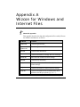
Appendix A Wizcon for Windows and Internet Files ...................A-1
Appendix B Converting Wizcon 5 Applications...........................B-1
Working with Wizcon 5 and Wizcon 7 ................................................................. B-2
Copying an Application to other Locations or PCs............................................ B-3
Wizcon 5 Compatibility ......................................................................................... B-4
Differences Between Wizcon 7 for Windows and Wizcon 5.1 for OS/2 ............ B-6
APIs ......................................................................................................................B-6
Communication Drivers ........................................................................................B-6
Image ....................................................................................................................B-6
Overcoming Image Font Differences ....................................................................B-7
Overcoming Image Size and Resolution Differences ...........................................B-9
Special Characters Consideration ..................................................................... B-10
Running Your Application the First time........................................................... B-11
xviii Wizcon for Windows and Internet User’s Guide
Appendix C Tuning Parameters ....................................................C-1
Overview ................................................................................................................. C-2
Tuning Parameters ................................................................................................ C-3
WIZTUNE.DAT ...................................................................................................... C-24
Appendix D VFI5FST (VFI Fast) .....................................................D-1
Advanced User Information .................................................................................. D-2
VFI5FST Tuning Parameters................................................................................. D-3
LGRBUFSIZE and LGRFLUSHTIME .................................................................. D-3
VFI_DAYS_PER_FILE......................................................................................... D-3
VFI5FST_IDX_SEC, VFI5FSTT_IDX_SEC ......................................................... D-4
VFI5FST_WRITE_BACK, VFI5FSTT_WRITE_BACK ........................................ D-4
VFI5FST_NO_COMM_ERR, VFI5FSTT_NO_COMM_ERR ............................... D-5
VFI5FST_MODE_TIMESTAMP, VFI5FSTT_MODE_TIMESTAMP .................... D-5
Appendix E Wizcon DOS to Wizcon 7 Conversion Utility ........... E-1
Wizcon DOS to Wizcon 7 Conversion Utility .......................................................E-2
Converting Wizcon for DOS Applications ............................................................E-2
Preparing the Wizcon for DOS Application...........................................................E-3
Initial Configuration ...............................................................................................E-4
Gate Conversion ...................................................................................................E-5
Template Conversion............................................................................................E-9
Miscellaneous .....................................................................................................E-15
Alarm Conversion ...............................................................................................E-16
Report Conversion ..............................................................................................E-17
Final Adjustments ...............................................................................................E-18
Troubleshooting ..................................................................................................E-25
Appendix F Networking with OPC Using DCOM.......................... F-1
Making OPC Connections ......................................................................................F-2
When You Can’t Make OPC Connections.............................................................F-2
Security for Windows NT and DCOM....................................................................F-3
Configuring DCOM................................................................................................F-4
Table of Contents xix
Different or Same Domains ..................................................................................F-6
Default Security Page ...........................................................................................F-7
Short-Term Security Problem Resolutions ........................................................F-11
Same User Logon...............................................................................................F-11
Disable DCOM Security......................................................................................F-11
Long-Term Security Problem Resolutions.........................................................F-12
Other Hints:.........................................................................................................F-14
Appendix G Wizcon ASCII (ILS) File Format ............................... G-1
Introduction ............................................................................................................ G-2
Document Conventions ........................................................................................ G-3
Appendix H Glossary .....................................................................H-1
Index ................................................................................................. I-1
xx Wizcon for Windows and Internet User’s Guide
Chapter 1
Using this Guide
About this chapter:
This chapter describes how to use this guide, as follows:
About this Manual, the following page, describes the chapters in this
user’s guide.
What You Should Know , page 1-6, describes things you should know
and the typographical convention used in this guide.
Registering Your Product, page 1-7, describes how to register your
product and how to receive technical support.
Using this Guide 1-1
About this Manual
Wizcon for Windows and Internet User’s Guide, designed for Wizcon
for Windows and Internet running under Windows NT and Windows 95
or 98 provides developers and system integrators with the necessary
information to build process and control applications with Wizcon.
If you are using Wizcon for Windows and Internet for the first time, you
may proceed in one of the following ways:
■
Read this guide from cover to cover, exactly as it is presented.
■
Read Chapters 1 through 5. These chapters provide you with basic
information on the Wizcon installation procedure, guidelines for
designing an application, and a description of the Wizcon
Application Studio. Then, read the chapters you need, depending on
the tasks you want to perform.
If you are an experienced Wizcon user, read Chapter 2, Introducing
Wizcon, to learn about the available features, and then use the Table of
Contents and the Index to find the information you need.
This guide contains the following sections:
Chapter 1, Using this Guide, covers basic information about this
manual.
Chapter 2, Introducing Wizcon , introduces Wizcon and its features.
Chapter 3, Installing Wizcon for Windows and Internet , describes the
system requirements and installation procedure.
Chapter 4, Getting Started, provides guidelines for building
applications with Wizcon.
Chapter 5, Getting to Know the Application Studio , describes the
operational framework of Wizcon.
Chapter 6, Communication Drivers, describes how to define
communication drivers and blocks.
1-2 Wizcon for Windows and Internet User’s Guide
Chapter 7, Tags, describes how to define and use tags, which are
contact points through which Wizcon receives data from the controller
and/or outputs data to it.
Chapter 8, Alarms, describes how to define and use alarms, which are
internal system messages that provide the operator with information
concerning events generated by the system.
Chapter 9, Events Summaries, describes different options for alarm
display: in a regular Events Summary window or in a Popup Event
Summary.
Chapter 10, Creating Events Summary Profiles, describes how to
define the way alarms are displayed in a browser.
Chapter 11, Creating Images and Picture Viewers, describes how to
work with Wizcon Images and how to create a Picture Viewer so that the
Image can be viewed in a browser.
Chapter 12, Image Editor, describes how to create and view images.
Chapter 13, Image Animation, describes the process of image
animation.
Chapter 14, Creating Trend Viewers, describes how to create and
modify a Trend Profile, to compare device functionality and correlate
actions and responses, and how to create a Trend Viewer that displays
these past and current events in a browser.
Chapter 15, Generating HTML Pages , describes how to generate and
edit HTML pages.
Chapter 16, Wizcon Language, describes how to create programs that
enhance system capabilities.
Chapter 17, Recipes, describes how to create, define and apply recipes
and model recipes. A recipe is a list of tag values that can be saved and
applied in specific control processes as a group, to cause the process to
enter a desired state. Each recipe belongs to a model, which is used to
group recipes and provide the list of tags from which the recipes are
derived.
Using this Guide 1-3
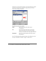
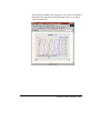
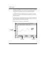
Chapter 18, Charts, describes how to define, edit and view charts to
provide graphical views of past and current activities recorded by the
Wizcon system.
Chapter 19, History Viewers, describes how to generate and use
History Viewer lists to provide you with simple and straightforward data
concerning tags and tag values over specific periods of time.
Chapter 20, Reports, describes how to define customized reports which
contain free text and calculated field data.
Chapter 21, Macros, describes how to define macros, special programs
that execute pre-defined actions, commands, or programs.
Chapter 22, Wizcon DDE Support, describes how to define Wizcon as
a DDE client or server.
Chapter 23, Wizcon Network , describes how to design and operate a
Wizcon Network.
Chapter 24, WizSQL -Wizcon SQL Support , describes how to use
WizSQL both as a client and server.
Chapter 25, Multiple Tags , describes how to define multiple tags.
These tags enables you to adjust system parameters and establish a
proper Wizcon application working environment.
Appendix A, Wizcon for Windows and Internet Files, describes data
and configuration files used by Wizcon.
Appendix B, Converting Wizcon 5 Applications, describes how to
convert Wizcon 5 applications to Wizcon for Windows.
Appendix C, Tuning Parameters, describes how to use tuning
parameters to optimize performance and enhance functionality.
Appendix D, VFI5FST (VFI Fast), describes the VFI5FST tuning
parameter.
Appendix E, Wizcon DOS to Wizcon 7 Conversion Utility, provides
instructions on how to convert Wizcon DOS applications to Wizcon 7
for Windows.
1-4 Wizcon for Windows and Internet User’s Guide
Appendix F, Networking with OPC Using DCOM , provides
instructions for accessing data from remote OPC servers using DCOM,
and explains how to troubleshoot DCOM problems with OPC servers.
Appendix G, Wizcon ASCII (ILS) File Format, describes the structure
and format of the Wizcon for Windows and Internet ASCII (ILS) file.
Appendix H, Glossary, provides a description of the terms and
definitions used in this manual.
Using this Guide 1-5
What You Should Know
Before you start using Wizcon and work through this user’s guide, you
should be familiar with the Windows NT and Windows 95 operating
systems. You should also know how to do the following:
■
Operate an IBM-PC or compatible.
■
Use a mouse.
■
Use a dialog.
Typographical Convention
This guide uses the following typographical conventions:
Ø This symbol indicates a menu or menu path, and the item within the
menu that you need to select to perform the task as it is described in
the section that follows. For example, Menu Ø Operator
Web-disabled
This symbol indicates that a feature is not supported or applicable
on the Web.
1-6 Wizcon for Windows and Internet User’s Guide
Registering Your Product
You are important to us, and it’s important for us to know who our
customers are. Registering your Wizcon product enables us to provide
you with better services and important notifications about the product.
Please take a minute to complete the Licensing Agreement included with
your product and send it to PC Soft.
Receiving Technical Support
You can receive technical support from your local distributor. To
receive prompt support, make sure that you complete the Registration
form and send it to PC Soft.
Using this Guide 1-7
1-8 Wizcon for Windows and Internet User’s Guide
Chapter 2
Introducing Wizcon
About this chapter:
This chapter describes Wizcon for Windows and Internet and its
features, as follows:
What is Wizcon for Windows and Internet? , the following page,
describes Wizcon.
Wizcon for Windows and Internet Main Features , page 2-4, describes
Wizcon Main Features.
Introducing Wizcon 2-1
What is Wizcon for Windows and Internet?
Wizcon is an advanced Supervisory Control and Data Acquisition
(SCADA) system used as an applications development tool that enables
system integrators to create sophisticated Supervisory and Control
applications for a variety of industries.
Wizcon is an application generator. This means that all the control and
monitoring facilities are already built into the system, and only the
project definitions need to be provided by the application engineer.
Minimal computer or programming skills are required.
Wizcon takes advantage of the powerful, preemptive, multi-tasking
capabilities of the Windows 95 or 98 and NT operating systems, and a
built-in event-driven mechanism to achieve the utmost performance and
data integrity. It also uses its interface mechanisms to implement clear
and efficient visualization of its components.
Wizcon for Windows and Internet enables you to integrate your
application with your Internet/Intranet network, promoting real-time
Supervisory and Control using real-time graphics and event-driven
information updates from any computing platform. It combines the
benefits of SCADA, Java, HTML and Internet.
Wizcon for Internet applications can be accessed and used without
requiring platform-specific software, client software installation, or
plug-ins. The production floor can be safely monitored and controlled
through a standard Web browser. You can also view both factory data
and corporate information through a common interface, from any
desktop or mobile computer.
A Wizcon application communicates with control equipment in the field,
such as Programmable Logic Controllers (PLCs), measuring
instruments, and other devices. As the equipment is monitored and data
is recorded, Wizcon responds according to system logic requirements or
operator requests.
2-2 Wizcon for Windows and Internet User’s Guide
Typical Wizcon SCADA Configuration
Introducing Wizcon 2-3
Wizcon for Windows and Internet Main Features
This section describes Wizcon main features and concepts. A glossary
appears at the back of this book in which you can find descriptions of
Wizcon terms and concepts.
Alarm Processing
When exceptional events occur, Wizcon selectively sends alarms to
special files, pop-up windows, a web client, Images and printers. If you
want to handle numerous alarms simultaneously, you can filter, sort and
divide the alarms according to zones, names and priorities. Operators
can acknowledge the reception of alarms and automatically receive
instructions for handling them.
Automatic Network Optimization
In cases where there are very fast tag changes on the Wizcon station, and
server is too loaded to send all the tag changes to web clients fast
enough, only the newest tag values will be sent to the web client.
■
In case the web client can not keep up with tag changes from the
Wizcon for Internet station, it will process the latest tag value.
■
This insures that the web client always displays the most updated
information possible, even if the server or the web client are loaded
and can not keep with the fast tag updates.
2-4 Wizcon for Windows and Internet User’s Guide
Background Processing
Wizcon enables you to process heavy jobs without temporarily disabling
the use of the Wizcon system.
The background processing feature operates when:
■
Loading an image file that is larger than 30K.
■
Printing an image.
■
Generating Events Summary and History Viewer reports.
■
When using MultiAdd, List, and Use functions in the Tag
Definition dialog. These functions are described in more detail in
Chapter 7, Tags.
While the background processing is in progress, you can perform other
operations.
The following is an example of a background Processing dialog:
The string above the Stop button in the dialog describes the task that is
currently being executed. The Stop button can be activated to end the
process. However, in some cases, the Stop button will not appear and no
termination will be possible. During the process, the percentage covered
will continuously be displayed in the dialog until the entire process is
completed.
Introducing Wizcon 2-5
Built-in Report Generator
Designed specifically for supervisory and control systems, this report
generator can produce customized daily shift reports, periodical reports,
and event-driven reports. For more sophisticated reports you can use
WizReport available on the Value Pack CD.
Charts and Reports
Wizcon charts provide graphical views of process behavior and
operational trends over a period of time. A single chart can display
historical and real-time trends in distinctive colors and styles.
You can configure an X-Y chart with up to 16 related process
parameters and scroll along the X and Y axis while zooming in and out
to view the desired details.
The Wizcon built-in report generator keeps you continuously informed
and up to date on all plant activities. Designed specifically for
supervisory and control systems, this report generator can automatically
produce customized daily shift reports, periodical reports, and eventdriven reports.
Database Connectivity
WizSQL module allows application designers to build event-driven SQL
queries to read and write Wizcon data from and to database tables. This
simplifies the exchange of information with other applications.
2-6 Wizcon for Windows and Internet User’s Guide
#«#coHo#o6H
Wizcon for Internet:
■
Reduces operating costs by enabling users to build a single
application instead of a networked solution of multiple applications.
■
Eases the administrative burden tremendously, since it is Java based
and Java is already an integral part of the web browser installed on
most desktops.
■
Need not be installed locally on each machine. Updates can be
distributed centrally through web servers.
■
Does not introduce new configuration, resource, or compatibility
issues; nor does it require extra administrative or maintenance effort
for each machine. In addition, Wizcon for Internet relies on Java’s
portability and eliminates the need to support different versions of
applications on different platforms.
Can be viewed online with just a browser.
Events Summary
Events Summaries display alarms according to the user’s specifications.
The user can apply a filter to display only those alarms from a certain
zone or of a certain priority. The alarms can also be sorted in the Events
Summary by the same criteria. A user can also decide what alarm
information is to be displayed, such as alarm start time, end time,
acknowledge time, and in what order those fields will appear.
Furthermore, you can rely on Wizcon’s foolproof, event-driven alarm
notification to detect all alarms in real time, ensuring that you never lose
data or miss alarms.
Introducing Wizcon 2-7
Events Summary Profiles
Events Summary Profiles determine how active alarms are displayed in a
browser according to the definitions defined by the system integrator.
Events Summary Viewer
An Events Summary Viewer features real-time monitoring of alarms
according to the definitions specified in the Events Summary Profile.
This enables the operator to:
■
Monitor and acknowledge alarms in real time.
■
Adjust alarm display, resize columns and change alert sorting.
■
Change the alarm filter and view only a specific type of alarm. For
example, from a certain zone or of a certain priority.
■
View HTML alarm assist files.
■
View alarm background and text colors set by alert severity and
zone.
Hot Backup Support
A Wizcon for SCADA station can serve as a backup to other stations. If
the main SCADA system fails, the backup station immediately takes
over and continues to function. ‘
Innovative Graphics Presentation
Wizcon employs the most advanced techniques for presenting graphics.
They include:
2-8 Wizcon for Windows and Internet User’s Guide
■
Drawing a single large image that represents the entire plant and
then zooming in on a selected area to obtain detailed views of small
and even hidden elements. In addition, your image can consist of
more than 64 layers, with each layer representing specific
information. Operators can then choose and mix layers, accessing
only the information they need and are authorized to see.
■
Defining dynamics so that as parameters in the field change, so do
graphical drawings and textual displays. For instance, if a tank is
filling, the respective tank drawing will be filled accordingly and the
display of the liquid level will be updated numerically.
■
Defining any object in the image as a trigger, so that whenever that
object is selected, one of several operations, such as macro
activation, will be automatically performed.
■
Designing an image using the Wizcon simple, yet powerful, graphic
editor that includes a variety of drawing tools designed specifically
for Wizcon for Internet requirements. A unique editing feature
enables you to easily modify any object and simultaneously apply
the changes to all the applications’ diagrams.
In addition to drawing images within the Wizcon framework,
graphic files that were generated using other software programs can
be imported to the Wizcon image editor.
■
Using the Wizcon clusters library with a variety of prebuilt objects,
including valves, pumps, and other industry-standard components.
You can define or change the parameters of each object and save the
changes in the Wizcon for Internet configuration database.
Millisecond Time Stamping
Wizcon samples PLCs at up to 50 milliseconds resolution and can
receive data with a time stamp of up to 1 millisecond resolution. This
data is registered in Wizcon history files according to the time stamp. It
allows operators to trace the sequence of plant events exactly as they
occurred.
Introducing Wizcon 2-9
Networking
The Wizcon solution provides a smooth growth path from a standalone
workstation, through the plant floor configuration, to plant-wide network
architecture that connects the plant floor with existing file servers and
other management systems.
The Wizcon network uses client-server architecture, allowing users to
transparently define network data objects without defining network tags
or alarms in the local configuration database.
Wizcon can be connected to other Wizcon stations or Wizcon stations
using NetBIOS or TCP/IP protocol. Thus, tags and alarms defined on
any Wizcon station can be used on the same network as Wizcon for
Internet.
Online Design
You can make changes during runtime and view the results immediately.
Open Architecture
Wizcon integrates seamlessly with your existing databases, spreadsheet
and other customized applications, allowing you to focus on productivity
rather than compatibility.
■
Wizcon Virtual File Interfaces (VFIs) enable the designer to select
different file formats to be used by WizPro for historical data
logging and report generation. The system engineer can use a
combination of different file systems and databases with the
application, for data manipulation convenience and optimum
performance.
■
A comprehensive set of Application Programming Interfaces (APIs)
is included with every Wizcon for Windows and Internet package to
enable smooth integration with customized programs and
application modules.
2-10 Wizcon for Windows and Internet User’s Guide
■
Wizcon supports two-way Dynamic Data Exchange (DDE) links for
exchanging data with other DDE-compatible applications.
■
Wizcon SQL Interface enables application designers to build eventdriven SQL queries to read and write Wizcon for Internet data from
and to database tables, simplifying the exchange of information with
other applications.
■
Wizcon is managed by a real-time, event-driven kernel called
WizPro. This module includes a set of APIs which can be used to
write supplemental Wizcon programs in C and Visual Basic
language, to meet the specific requirements of any project. For
further information, refer to the Read Me file located in the Wizcon
Toolkit.
■
Wizcon is compatible with a wide variety of PLCs and other control
system components. Custom adaptation is supported through a fully
documented toolkit.
■
Wizcon’s OPC capabilities enable system integrators to create a
common interface for exchanging data with hardware field devices
or other software that can be reused by this client program, and other
HMI, SCADA and custom applications.
c6¦HcH©H
This feature displays an online dynamic graphical drawing representing
the factory floor. It serves as the operator's main tool for viewing,
interacting with and controlling the factory floor, through dynamic
graphic representation.
PLCs Sampler
Wizcon samples PLCs at up to 50 milliseconds' resolution and can
receive data with a time stamp of up to 1 millisecond resolution. Wizcon
can sample up to 16 networks of PLCs and other field devices.
Introducing Wizcon 2-11
Recipes
Wizcon provides recipes - lists of tag values that are applied to specific
control processes as groups.
Operators can edit, load and save recipes for convenient handling of
production processes and setting of control programs. Recipe
management and downloading of production recipes from management
systems is simple and straightforward.
H6¦c«ro`HH,
Wizcon applications take full advantage of the security features
provided by the Web server, enabling user access control according to
selected Web pages. A Firewall can be used to limit access according to
IP addresses. Wizcon also offers the system integrator the power to limit
the operations that the user is able to perform.
Tags
A Wizcon tag is used as an internal variable for:
■
Calculations and display.
■
Communication with PLCs in order to represent data from PLC
memory, or to send commands to PLCs.
Tag values can be scanned and recorded to historical files according to
several parameters specified by the user. Tags can also be assigned a
DDE link definition and can therefore receive or send data to/from other
applications.
2-12 Wizcon for Windows and Internet User’s Guide
Trend Profiles
The Trend feature provides real time and historical graphical view of
tags’ values over time.
Wizcon architecture provides additional benefits for remote control
applications and applications where frequent causal access is required.
For those applications historical display of data is critical. In such
applications an operator may wish to log in to his application at the end
of the day and check what happened during the day.
The Trend features include:
■
Historical cache mechanism: Offers improved performance with
minimum load on the server.
■
Asynchronous historical data download: As a result the Trend is
always responsive to the user.
■
Performance: On a local area network, performance is similar to
Wizcon for Windows. It is possible to use trends over dial-up
connection.
■
Display of multiple tags over time.
■
Historical and on-line data support.
■
X and Y axis labeling.
■
Offers different line colors and line types.
■
The Trend component takes less than 400K to download.
Trend Viewer
A Trend Viewer displays online past and current activities recorded by
the Wizcon for Internet system according to definitions specified in the
Trend Profile.
Introducing Wizcon 2-13
Wizcon Language
Wizcon includes a built-in control language called Wizcon Language,
which can be used to automate plant tasks, augment control capabilities,
and enhance system flexibility.
This language enables application engineers with little programming
expertise to write useful command programs. Each system function,
such as access to control devices, can be expressed in symbolic form in
Wizcon Language, so that any application engineer can customize the
application to meet specific plant design requirements.
Year 2000 Compatibility
Wizcon is compatible with the year 2000. Note that the support is up
to 2036.
2-14 Wizcon for Windows and Internet User’s Guide
Chapter 3
Installing Wizcon for
Windows and Internet
About this chapter:
This chapter describes Wizcon for Windows and Internet, Version 7.5,
system requirements and the installation procedure.
System Requirements, on the following page, describes the required
Wizcon for Windows and Internet system requirements.
Installation, page 3-4, describes how to install (and uninstall), Wizcon
for Windows for Internet.
Starting Wizcon for Windows and Internet , page 3-10, describes how
to start Wizcon for Windows and Internet
Installing Wizcon for Windows Internet 3-1
System Requirements
Before you install Wizcon, verify that you have the following:
Hardware
Computer: 200MHz Pentium, or higher.
Memory: 64MB minimum.
Hard Disk: 120 MB minimum free.
Display: VGA, SVGA, or any graphic adaptor that supports the
operating system desktop. The display should be set at 256 colors or
higher and the screen resolution should be set at 640 x 480 or higher.
Mouse: Any PC compatible mouse.
Parallel Port: Required for the Wizcon security plug.
Software
Operating System: Microsoft’s Windows NT version 4.0 (or higher), or
Microsoft’s Windows 95, 98 can be used for application development.
■
Properly configured TCP/IP: A fixed IP address is required for a
web server. Or Windows 95,98 NetBEUI Protocol.
■
Web server: A web server is required for publishing the
application, (not for development).
■
Browser: A Java 1.1-enabled browser is required. Netscape
Communicator 4.0 or higher, or Microsoft Internet Explorer 4.1.
■
HTML Editor: Any HTML editor may be used.
3-2 Wizcon for Windows and Internet User’s Guide
The following is required to publish a Wizcon application on the Web.
■
Windows NT 4.0.
■
Java 1.1-enabled browser
■
A web server. For example the Netscape FastTrack Server 2.1
that can be downloaded from the Netscape web site at
http://www.netscape.com), or the Microsoft Internet Information
Server that can be downloaded from the Microsoft web site.
Installing Wizcon for Windows Internet 3-3
Installation
It is strongly recommended that you close and exit all Windows
programs before running the installation procedure.
➤
To install Wizcon:
1. Insert the CD-ROM into the CD-ROM drive. The WizFactory Setup
menu is automatically displayed:
The Master Setup program contains the following options:
■
Wizcon for Windows and Internet: Loads the Setup
program for the Wizcon for Windows and Internet
installation program.
■
WizPLC: Loads the Setup program for WizPLC installation
program.
3-4 Wizcon for Windows and Internet User’s Guide
■
WizDCS: Load the Setup program for WizDCS.
■
Wizcon Demo Applications: Enables you to install Wizcon
demo applications, such as Chemicals and Building and Water.
Different demo applications run on Windows 95/98 and
Windows NT. The resolution of your screen should be set to
either:
Resolution 1024 x 768 or
Resolution 800 x 600
■
Explore the CD: Opens Windows Explorer, enabling you to
view the CD contents.
■
Exit: Exits the Master Setup program.
If the menu is not automatically displayed. Click on the Start
button, select Run and enter: D:\setup.exe into the Open field,
where “D” is your CD-ROM drive. Click OK.
2. Select Wizcon for Windows and Internet The Welcome dialog is
displayed:
Installing Wizcon for Windows Internet 3-5
3. Click the Next button to continue the installation. The Choose
Destination Location dialog is displayed:
4. If you have a previous version of Wizcon installed, you are
prompted to overwrite the previous version or to Exit the
installation, in the following note:
It is recommended to click Yes to overwrite the previous
installation.
5. Click the Next button to install Wizcon in the default folder:
(C:\WizFactory\Wizcon). Click the Browse button if you want to
change the default directory.
3-6 Wizcon for Windows and Internet User’s Guide
6. Press the Next button and the Select Components dialog is
displayed:
In this dialog, you can select the following components for
installation:
System Files: Select this option to install the Wizcon for
Windows and Internet application files in the directory
specified in the Destination Directory field in this dialog. The
default directory is C:\WizFactory\Wizcon.
Communication Drivers (Optional) : Select this option if you
are using an external driver or controller. You can then select
the drivers you want to install from a list of existing Wizcon
device drivers. Press the Change button to open another dialog
where you select the drivers you wish to install.
The dialog specifies the default directory in which Wizcon will
be installed.
Installing Wizcon for Windows Internet 3-7
Getting Started - Web: Select this option to install the Wizcon for
Internet Getting Started tutorials (Exercise and final applications).
Getting Started - Windows: Select this option to install the Wizcon
for Windows Getting Started tutorials (Exercise and final
applications).
It is recommended to select the Wizcon System files option. Click
the Next button. The Select a Language dialog is displayed:
Please note that you will not receive the Select Language dialog if
you did not Check (ä) the System files.
7. Choose one of the languages that you want to install. Wizcon is
localized for English, French, German, Chinese, Japanese, and
Polish.
8. Press the Next button. A progress bar is displayed and the
installation begins. When installation is complete the Finish Reboot
dialog is displayed. Click Yes to restart your PC or click No to
update later. It is recommended to restart your PC immediately after
installation.
3-8 Wizcon for Windows and Internet User’s Guide
9. Click Finish. Installation is complete.
Uninstalling Wizcon for Windows and Internet
Wizcon includes an Uninstall utility which you can use to remove
Wizcon for Windows and Internet from your computer. The utility will
only remove the directories, files, folders, icons and registration
originally created by the Wizcon for Windows and Internet Installation
program.
To achieve the best results, exit Wizcon and make sure that WizPro is
not running in the background before using the Uninstall program. If
WizPro is working, some files and icons may not be removed.
Installing Wizcon for Windows Internet 3-9
➤
To launch the Wizcon for Windows and Internet Uninstall Program:
1. Click on the Start button on your desktop, point to Settings and
then click on Control Panel. The Control Panel folder is displayed.
2. Double-click on the Add/Remove Programs icon. The Add/Remove
Program Properties dialog is displayed.
3. Select Wizcon for Windows and Internet from the list of available
programs and click the Add/Remove button.
4. When the program has been removed, click the OK button to close
the dialog.
Starting Wizcon for Windows and Internet
To start Wizcon, click on the Start button on your desktop, point to
Programs, to WizFactory and then to Wizcon. Click on Wizcon to
open the Studio.
Or,
Double-click on the shortcut to Wizcon icon
➤
on your desktop.
To create a shortcut to your Wizcon application (without going
through the Project Wizard):
1. Right-click on your desktop, and select New from the popup menu.
2. Select Shortcut from the popup menu. The Create Shortcut dialog
is displayed.
3. Type the location and name of your application (*.wz7) or search
for the application by clicking on the Browse button.
4. Press Next and select a name for the shortcut.
5. Press Finish to complete the operation.
3-10 Wizcon for Windows and Internet User’s Guide
Chapter 4
Getting Started
About this chapter:
This chapter describes how to open Wizcon, and suggests a workflow
for building an Wizcon application, as follows:
Accessing Wizcon, on the following page, describes how to open
Wizcon and the Wizcon Application Studio. A description of the Quick
Access bar is also provided.
Designing an Application, page 4-5, describes what to do before you
begin designing an application, as well as typical application
requirements.
Wizcon Workflow , page 4-9, describes a typical workflow for
application design.
Shutting Down , page 4-18, describes how to logout of the system and
how to exit Wizcon.
Getting Started 4-1
Accessing Wizcon
You can access Wizcon and all its working components in two steps:
■
Step 1: Opening Wizcon, as described below.
■
Step 2: Opening the Wizcon Application Studio, which contains all
the components you need to design an application, as described
below.
Opening Wizcon
When you open Wizcon, a The Getting Started Wizard dialog is
displayed, which enables you to open applications from the Wizcon
Application Studio. The Getting Started Wizard is described in more
detail in the Using the New Wizcon Application Wizard section of
Chapter 5, Getting to Know the Application Studio.
➤
To access Wizcon:
1. Click the Start button on your desktop and point to Programs.
Point to WizFactory, point to Wizcon and select Wizcon from the
popup menu. The Wizcon Getting Started Wizard is displayed. Once
you have created the type of application you want, The Quick
Access bar is displayed:
The Quick Access bar is described in more detail on the following
page.
button in the Quick
2. Click on the Wizcon Application Studio
Access bar to access the Wizcon Application Studio. The Wizcon
Application Studio is described in more detail in Chapter 5, Getting
to Know the Application Studio.
4-2 Wizcon for Windows and Internet User’s Guide
You can now define yourself as a default user, so that next time you
access Wizcon you can login to the system with a name and password.
Defining users is described in more detail in Chapter 5, Getting to Know
the Application Studio.
Quick Access Bar
The Quick Access bar enables you to:
■
Login and out of the system.
■
Open the Wizcon Application Studio for application design.
■
Load an image, an Events Summary, a Chart and a History Viewer.
■
Load and Save Recipes
■
Open multiple tags.
■
Open a single tag input
■
Initiate Wizcon shutdown.
The main function of the Quick Access bar is to enable a user to initiate
the following actions during runtime. These actions can be customized
so that only authorized users can initiate them, as described in the
Operator Access Authorization section of Chapter 5, Getting to Know
the Application Studio.
Select
To do
Open the Wizcon Application Studio, as described in
Chapter 5, Getting to Know the Application Studio.
Load a layout file (*.lay).
Capture the layout of your open windows, and save them.
Load an image file (*.vim). Images are described in more
detail in Chapter 12, Image Editor.
Getting Started 4-3
Select
To do
Load an Events Summary file (.ann). Events Summaries
are described in more detail in Chapter 9, Events
Summaries.
Load a chart file (.chr). Charts are described in more
detail in Chapter 18, Charts.
Load a History Viewer file (.anl). History Viewer files are
described in more detail in Chapter 19, History Viewers.
Load a recipe file, as described in Chapter 17, Recipes.
Save a recipe, as described in Chapter 17, Recipes.
Open the multiple tags utility, as described in Chapter 25,
Multiple Tags.
Opens a Single Tag input, as described in Chapter 7,
Tags.
Users Setup, as described in Chapter 5, Getting to Know
the Application Studio.
Login to Wizcon.
Logout of Wizcon.
Exit Wizcon, as described on page 4-18.
4-4 Wizcon for Windows and Internet User’s Guide
Designing an Application
A carefully designed application enables a user to easily and efficiently
supervise an on-going process. This section describes the following:
■
The basic information you need before designing an application, as
described below.
■
Typical application requirements, as described on the following
page.
Before Designing Your Application
Before you start designing your application, you need to know some
basic, but necessary details about the process for which you are creating
the application:
■
Obtain a list of variables that Wizcon will read and write from and
to a PLC (I/O list or Tag list).
■
Look at the control drawings to study the design and use of certain
equipment.
■
Look at the plant drawings to examine the layout of the plant for
which you are designing the system.
■
Find out what kind of reports users and managers want to receive, in
what format and inclusive of what fields.
■
Find out what kind of network you have, if it uses the NetBIOS or
TCP/IP protocol, and the name of your network station.
■
Determine any authorization definitions.
■
Determine PLC definitions, such as blocks and addresses.
Once you have this background information, you can build an
application that fully uses the resources of the plant’s equipment.
Remember that if you are not aware of the limitations of the equipment,
you may cause damage.
Getting Started 4-5
If you are creating an application for a networking environment, refer to
Chapter 23, Wizcon Network before you start designing the application.
Designing Multiple Applications
If you are designing multiple applications, you need to decide where
to store your history files: on the local disk or on the server.
Using Wizcon network tags, the same application can run on many
stations. The application can be designed on one station and copied to
another station. The only difference will be the station name definition
(and number).
Note: The tag, alarm and communication driver definitions should not
be copied.
Tip: It is recommended to define the station name and number before
you begin to build your application (images, charts and so on).
Typical Application Requirements
A successful Wizcon application takes into account the following:
Consistent Display Design
Process visualization accurately represents an on-going plant process,
enabling a user to clearly understand the process status at any given
time.
It is recommended that displays in the visualization remain consistent
throughout the application. For example, if a tanks fill status is
represented in percentage form, then all fill status should be represented
in percentages.
4-6 Wizcon for Windows and Internet User’s Guide
Alarm Design
Alarms represent one of the most significant occurrences in a process. It
is important to design alarms with different severity levels, zones and
characteristics. This way, a user will recognize each alarm and react
quickly and properly. It is important to mark all alarms that are not
targeted to an Events Summary with an Auto Ack attribute so that they
will not have to be acknowledged by the operator. For more details
about alarms, refer to Chapter 8, Alarms.
Chart Design
Charts visually represent the process progression. When designing
charts, you should take into account user requirements. For example, if a
user needs to compare two tags to perform a certain task, it is
recommended to include both tags on the same chart. Up to 16 tags may
be represented on a single chart. For more details about Charts, refer to
Chapter 18, Charts.
Tag Naming Conventions
Make sure that the name you assign to each tag clearly indicates what
the tag represents. For example, all the tags that represent Flow
Transmitters may be called FTxxx. This naming method is also
convenient when adding a list of tags that are of the same type.
It is also recommended to name the stations in a predetermined manner.
For example, according to plant area.
Logic
You can use Wizcon Language to create an application that can enhance
the capabilities of control equipment working with Wizcon such as
PLCs, and establish the connectivity interface between Wizcon and
external computer applications. For more details about Wizcon
language, refer to Chapter 16, Wizcon Language.
Getting Started 4-7
Wizcon enables you to define compound tags. A compound tag is a
linear calculation based on values of other tags. Compound tags are
described in more detail, in Chapter 7, Tags.
The Wizcon scripting language can also be used to implement logic. In
addition to providing connectivity to SQL databases, WizSQL has
powerful language functions and its event driven architecture provides
excellent performance.
4-8 Wizcon for Windows and Internet User’s Guide
Wizcon Workflow
This section describes a workflow with which to build an application.
The following sections describe each step in the workflow in more
detail.
Step 1:
Defining Communication
Drivers and Blocks
Step 2:
Defining User
Groups
Step 3:
Defining Tags
and Alarms
Step 4:
Building the
Application
Image
Step 5:
Defining
logic
Step 6:
Testing the
Application
Step 7:
Defining
Charts, Reports
and Recipes
Step 8:
Fine-tuning the
Application
You can reverse the order of
these steps if you use the
Wizcon cluster technology.
Getting Started 4-9
You can merge steps 3 and 4 into one, and complete the step in four
stages:
■
Define some of the tags.
■
Build part of the image.
■
Complete the image.
■
Define the remaining tags.
Tip: If you are building a network application, you should define a
network name and number before you begin the workflow. Remember to
restart Wizcon.
Step 1: Defining Communication Drivers and Blocks
Blocks are to be defined logically to maximize the efficiency of Wizcon.
This is done by defining blocks according to common sampling rates
and consecutive addresses in the PLC.
After defining communication drivers and blocks, you need to restart
Wizcon for changes to take effect.
When defining blocks, avoid:
■
Leaving gaps of more than 20 addresses within the block.
■
Defining blocks with a sampling rate that is different from the
individual tag sampling rate.
■
Defining the same tags in more than one block.
■
Defining large blocks.
For more details about defining communication drivers and blocks, refer
to Chapter 6, Communication Drivers.
4-10 Wizcon for Windows and Internet User’s Guide
Step 2: Defining User Groups
Defining user groups is important at this stage because each subsequent
design level may call for user authorization. Once you define the user
groups, you can add individual users at any time to any group.
Defining user groups later on in the design process is possible, but not
recommended. For example, in a car production plant, engineers,
managers and floor workers have different levels of authorization. If you
assign authorization rights early in the design process, you will save
valuable time in later stages of the design.
For more details about defining User Groups, refer to the Operator
Access Authorization section in Chapter 5, Getting to Know the
Application Studio.
Step 3: Defining Tags and Alarms
Defining Tags
Tags are I/O points that are mapped from the PLCs to Wizcon as well as
to internal (dummy) and calculated (compound) variables. You can use
tags in images, charts, alarms and all Wizcon functions.
When defining tags, make sure that tag and block sample rates do not
conflict with each other.
For more details about defining tags, refer to Chapter 7, Tags.
Defining Alarms
Once you define the tags, continue by defining the alarms. Alarms notify
a user of an event in the process. They can:
■
Indicate the beginning of a process.
■
Warn of a failure in part of the process.
Getting Started 4-11
When defining alarms it is possible to:
■
Set different severity levels to control the grouping and displaying
of the alarms.
■
Target serious alarms to a pop-up window, ensuring that users will
not perform any Wizcon function before clearing the alarm. This is
recommended.
■
Group alarms in families.
■
Assign an alarm to an object in an image. This object will then
change its graphical attributes whenever the alarm conditions are
met.
■
Assign a Help file to each alarm so the user will know what to do
when an alarm begins.
For more information about defining alarms, refer to Chapter 8, Alarms.
For more information about displaying alarms, refer to Chapter 9,
Events Summaries.
Step 4: Building the Application Image
The image is a graphical representation of the application process and
represents the feedback that the user receives from the plant. The image
is the main part of the application that a user views. Therefore, it should
be informative, yet easy to understand.
When designing images, take advantage of the following features:
■
The Wizcon Image Editor that features many different toolboxes to
enable you to build your application.
■
Zones, different areas of the image that can be viewed in close up.
Each zone can represent a different part of a plant process.
■
Layers, that can be compared to transparent sheets with the same
coordinates, which lay on top of each other. You can enable group
access to certain layers and thereby control sensitive information.
4-12 Wizcon for Windows and Internet User’s Guide
■
Cluster libraries, that use object-oriented technology to simplify and
speed up application design and maintenance. A cluster is an object
with pre-defined behavior patterns which can be linked to existing
tags and alarms, or can be used to automatically create new tags and
alarms.
■
The Wizcon Image Editor that features many different toolboxes to
enable you to build your application.
For more details about defining images, refer to Chapter11, Creating
Images and Picture Viewers, Chapter 12, Image Editor and Chapter 13,
Image Animation.
Step 5: Defining Wizcon Language
Wizcon Language commands are used to make logic calculations that
the PLC cannot perform. Wizcon Language is written and implemented
according to If, Then conditions. For example:
IF: @FLAG =1
THEN: REPORT “Shift”
Some examples of Wizcon Language commands include:
■
Starting and stopping a process.
■
Loading a recipe.
■
Writing to a tag value based on another tag value.
■
Writing to a file or printer.
For more details about defining Wizcon Language commands, refer to
Chapter 16, Wizcon Language.
Getting Started 4-13
Step 6: Testing the Application
At this stage of the design process, it is recommended that you test your
application to check your image, alarm, tag and block definitions.
After completing the test and implementing the necessary changes, you
can continue to define your reports, charts, recipes and fine tune the
application.
Step 7: Defining Charts, Reports and Recipes
Defining Charts
Charts provide graphical views of past and current tag values. You can
use charts to follow a trend or compare values. You can define up to 16
tags on a single chart.
When defining a chart, it is possible to:
■
Define a unique color to each chart that is also used by the scales of
the chart.
■
Determine that charts show online or historical activities.
For more details about defining charts, refer to Chapter 18, Charts.
Defining Reports
You can define reports for different users such as: operators, engineers,
and managers. Make sure that each report includes the required
information for the designated user.
Reports can be:
■
Triggered in Wizcon Language.
■
Written to a file.
■
Sent directly to the printer.
4-14 Wizcon for Windows and Internet User’s Guide
When designing reports, it is possible to:
■
Place fields in different positions and include any text, such as a
header or short explanation at the end of the report. The fields can
represent runtime values and a number of calculations performed on
the historical tag values, such as averages, integrals, sums and more.
■
Choose the range calculation, such as start day, start time, end day
and end time.
■
Define compound fields that are based on two other fields according
to a specific formula. Multiple fields allow you to receive a value
based on a group of other fields.
For more details on defining reports, refer to Chapter 20, Reports.
Defining Recipes
Recipes are specified sets of tag values that you can store for future use.
When defining recipes, remember that:
■
Each recipe must belong to a model which includes tags for certain
processes or production modes. The recipe uses the tags in the
model to which it belongs, but can also include tags that are not
defined in the model.
■
Each model and recipe has a unique name.
■
The same tag can belong to more than one recipe.
■
You can save the current values of any tags at any time as a recipe.
This means that at the end of a process, you can save its values as a
recipe and reload the recipe when the process is resumed.
For more details about defining recipes, refer to Chapter 17, Recipes.
Getting Started 4-15
Step 8: Fine-Tuning the Application
Once you have completed these steps, it is recommended to check all
your definitions. Use the Single Tag Value which is described in
Chapter 7, Tags, to:
■
Invoke Wizcon Language commands.
■
Initiate dynamic behavior in an image.
■
Invoke reports.
■
Check alarms.
Once you are satisfied with the results, fine-tune your entire
application, by:
■
Adding users to the user groups, as described in the Operator Access
Authorization section in Chapter 5, Getting to Know the Application
Studio.
■
Saving layouts that can be loaded upon login.
■
Setting the menus that will be displayed for the different user
groups, as described in the Operator Access Authorization section in
Chapter 5, Getting to Know the Application Studio.
4-16 Wizcon for Windows and Internet User’s Guide
Shutting Down
This section describes how to logout of Wizcon and how to exit the
system.
Logout
After initiating logout, you will not have access to the system until you
login again.
➤
To logout:
Click the Logout
button in the Quick Access bar.
Exiting Wizcon
You can exit Wizcon from the Quick Access bar or from the Wizcon
Application Studio.
➤
To exit Wizcon:
Click the Exit
button in the Quick Access bar.
or,
From File menu in the Wizcon Application Studio, select Exit Wizcon.
Getting Started 4-17
4-18 Wizcon for Windows and Internet User’s Guide
Chapter 5
Getting to Know the
Application Studio
About this chapter:
This chapter describes the Wizcon Application Studio which is the
operational framework of Wizcon for Windows and Internet, as follows:
Overview , page 5-3, describes how to open and exit the Wizcon
Application Studio, its structure, and tool bar.
Menu Options , page 5-12, describes the available menu options.
This chapter also describes the following:
Optimizing Application Performance, page 5-15, describes how to use
the Station properties to optimize Wizcon performance and enhance
functionality.
Application Setup, page 5-22, describes how to set up additional add-
ons and programs to run automatically while starting Wizcon.
Defining System Options, page 5-26, describes how to define system
options such as, setting WizPro options, changing default file paths and
specifying active printers.
Operator Access Authorization, page 5-32, describes how to control
local access to the Wizcon system such as registering system operators
and assigning names and authorization groups.
MultiLanguage Support , page 5-41, describes how the tag description,
alarm text and the text field of an image, developed in one langauge can
be translated to another.
Getting to Know the Application Studio 5-1
Layouts, page 5-47, describes how to save default window layouts.
Using the New Wizcon Application Wizard, page 5-51, describes using
the New Wizcon Application Wizard to open applications from the
Wizcon Application Studio.
5-2 Wizcon for Windows and Internet User’s Guide
Overview
The Wizcon Application Studio is opened from the Quick Access bar,
which is displayed when Wizcon is opened. It has an Explorer-like
interface which offers full control and access to all parts of the system
during application development.
There is no need for the Wizcon Application Studio to be displayed
during runtime and a developer can minimize it to obtain an
unobstructed view of the plant process. An operator can use the Quick
Access Bar for various actions during runtime.
➤
To open the Wizcon Application Studio:
1. Click the Wizcon Application Studio
button in the Quick
Access bar. The Wizcon Application Studio is displayed together
with the Tip of the Day window.
Getting to Know the Application Studio 5-3
2. You can deselect Show Tips on Startup if you do not want to
display the Tip of the Day window when you next open Wizcon for
Windows and Internet, or click Next Tip to display another tip.
3. Click Close to close the window. The Wizcon Application Studio is
displayed as follows:
It is divided into two frames:
■
All Containers, on the left, as described on page 5-7.
■
Control panel, on the right, as described on page 5-11.
5-4 Wizcon for Windows and Internet User’s Guide
The Wizcon Application Studio window also contains:
■
A menu bar through which you can access Wizcon for Windows
and Internet operational menus, which is described in more
detail on page 5-12.
■
A toolbar that enables quick access to the Wizcon Application
Studio most frequently used functions, as described below:
Click
To do
Open an image, as described in Chapter 12, Image
Editor.
Save the current application.
Define a tag, as described in Chapter 7, Tags.
Add alarm definition, as described in Chapter 8,
Alarms.
Generate a new HTML file, as described in
Chapter 15, Generating HTML Pages.
Create an Events Summary Profile, as described in
Chapter 10, Creating Events Summary Profiles.
Create a Trend Viewer, as described in Chapter 14,
Creating Trend Viewers.
Create an image, as described in Chapter 12, Image
Editor.
Create a new Events Summary, as described in
Chapter 10, Creating Events Summary Profiles.
Create a chart, as described in Chapter 18, Charts.
Create a History Viewer, as described in Chapter 19,
History Viewers.
Getting to Know the Application Studio 5-5
Click
To do
Create a new recipe model, as described in
Chapter 17, Recipes.
Define a layout, as described on page 5-47.
Create a report, as described in Chapter 20, Reports.
Display Wizcon version information.
5-6 Wizcon for Windows and Internet User’s Guide
All Containers Section
The All Containers panel displays a hierarchical structure, or tree, of the
containers from which you build a Wizcon application. Containers can
be thought of as the building blocks of a Wizcon application. The tree is
made up of three main folders of containers with the current application
as its root.
■
Web Application, contains the elements that are used to publish an
application, such as HTML pages for the Image and the Events
Summary Profile, and the Trend Profiles.
■
Files, contains the Wizcon elements that are stored as files, such as:
Images, Events Summaries, Charts, History Viewer, Model Recipes,
Layouts and Reports.
■
Objects, contains the elements that are stored as objects, such as:
Tags and Alarms.
Clicking the right-mouse button on any of the containers opens a popup
menu that displays related options. For example, right-clicking on
Alarms displays a popup menu with the following options: Add Alarm,
Import Alarms, Export Alarms and Properties.
Getting to Know the Application Studio 5-7
When a container is selected in the All Containers section on the left, a
list of its contents is displayed in the List Zone on the right. For example
when Alarms is selected in the All Containers list, a list of all the
alarms in the application is displayed in the List of Alarms, as shown
below.
All lists, for example the List of Alarms shown above, share the
following common features:
■
Right-clicking anywhere in the list displays a popup menu with
context sensitive options.
■
Clicking on a column header sorts the list in that column. The
information for each list is displayed under columns that are relevant
to the list. For example, the List of Alarms displays the following
columns: Tag Name, Condition, Text, Family, Zone and Severity.
5-8 Wizcon for Windows and Internet User’s Guide
■
A list can be duplicated in a separate window for ease of use by
right-clicking in the list window, pointing to View and selecting
Duplicate from the popup menu. A list can be duplicated only once.
For example, the List of Alarms as shown below:
■
A list can be customized by right-clicking in the list window,
pointing to View and selecting Settings from the popup menu. A
dialog is displayed in which you can set the order and the type of
fields to be displayed in the List Zone.
Getting to Know the Application Studio 5-9
For example, the List of Alarms dialog, as shown below:
To specify the columns to be displayed in the List of Alarms, click
the checkbox next to a column name to select it. The following
columns are available:
Tag Name
Condition
Text
Family
Zone
Severity
You can determine the order in which the columns appear in the
Wizcon Application Studio by selecting a column and activating the
Move Up or Move Down buttons.
You can select all the columns by activating the Select All button,
and deselect them by activating the Deselect All button. Clicking the
Default button selects all the columns.
5-10 Wizcon for Windows and Internet User’s Guide
The Control Panel
The Control panel, on the right of the Wizcon Application Studio, is
displayed when the root of the tree (the current application) is selected.
For example, on page 5-4, the application called wizapplication (the
default name Wizcon for Windows and Internet gives to new
applications) is selected and the Control panel is displayed. The Control
panel displays icons that represent the following elements of Wizcon for
Windows and Internet.
Click
To do
Define communication drivers, as described in Chapter 6,
Communication Drivers.
Define users, as described on page 5-34.
Define group names, as described on page 5-37.
Define printer settings, as described on page 5-30.
Define multiple tags, as described in Chapter 25, Multiple
Tags.
Define a single tag, as described in Chapter 7, Tags.
Define DDE blocks, as described in Chapter 22, Wizcon
DDE Support.
Define application setup, as described on page 5-22.
Define macros, as described in Chapter 21, Macros.
Set a network environment, as described in Chapter 23,
Wizcon Network.
Define Wizcon Language, as described in Chapter 16,
Wizcon Language.
Getting to Know the Application Studio 5-11
Menu Options
Menu bar
The following menu options are available in the Wizcon Application Studio.
Menu
Select
To do
File
New
Open a new HTML file, Events Summary
Profile, Trend Profile, Layout Capture, Image,
Events Summary, Chart, History Viewer,
Recipe Model and Report.
Opens an existing Image.
Display the New Application wizard in which
you can open a application, as described on
page 5-51.
Open an existing application, as described on
page 5-54.
Save the current project.
Save the current project with a specific name
and location.
Exit Wizcon for Windows and Internet.
Display (or hide) the toolbar.
Display (or hide) the status bar.
Disable non-Web features in the Image.
Open
New Application
Open Application
Save
Save As…
View
Exit Wizcon
Tool bar
Status bar
Disable non-Web
Features
Window System
Menu
Display (or hide) the icon in the top left corner
of the image window. This overwrites the
System menu property of the image window
attribute, as described in Chapter 12, Image
Editor.
5-12 Wizcon for Windows and Internet User’s Guide
Menu
Select
To do
Design
Add Object
Add a new tag, as described in Chapter 7,
Tags, or add a new alarm, as described in
Chapter 8, Alarms.
View the drivers defined for the application,
add a new driver, remove a driver, and define
driver properties, as described in Chapter 6,
Communication Drivers.
Define macros, as described in Chapter 21,
Macros.
View the DDE blocks defined for the
application, add a new block, delete a block
and define block properties, as described in
Chapter 22, Wizcon DDE Support.
Set up additional add-ons and programs to run
while starting Wizcon, as described on
page 5-25.
Communication
Drivers…
Macros
DDE Blocks…
Application
Setup…
PopUp Settings
Class Names…
Wizcon Language
Options…
Authorization
Design a Popup Events Summary which
appears on the screen to inform the operator of
severe alarms, as described in Chapter 9,
Events Summaries. Popup Events Summaries
are allocated to an alarm during alarm
definition, as described in Chapter 8, Alarms.
Assign class names to alarms, as described in
Chapter 8, Alarms.
Define Wizcon language procedures, as
described in Chapter 16, Wizcon Language.
Configure application options such as WizPro,
Paths and Printers, as described on page 5-24.
Configure operator access authorization, as
described on page 5-34.
Getting to Know the Application Studio 5-13
Menu
Select
To do
Network
Local Station
Configuration…
Configure your computer as a SCADA or
SCADA View station, a Hot Backup Station, or
a Management View Station, as described in
Chapter 23, Wizcon Network.
Record Remote
Data…
Record remote tags and alarms, and simulate
the connection between a remote station that is
not running, as described in Chapter 23,
Wizcon Network.
Set your network environment and establish a
proper Wizcon application performance, as
described in Chapter 23, Wizcon Network.
Assign an immediate value to a tag. This is
useful for testing tag performance, as described
in Chapter 7, Tags.
Define multiple tags to optimize performance,
as described in Chapter 25, Multiple Tags.
Import a list of tags, as described in Chapter 7,
Tags, or a list of alarms, as described in
Chapter 8, Alarms.
Export a list of tags, as described in Chapter 7,
Tags, or a list of alarms, as described in
Chapter 8, Alarms.
Network
Properties…
Tools
Single Tag…
Multiple Tags…
Import
Export
Help
MultiLanguage
Support
Help Topics
Tip of the Day…
About studio…
Define Language Support, as described on page
5-41.
Display Help topics
Display the Tip of the Day dialog.
Display information about the Wizcon
Application Studio.
5-14 Wizcon for Windows and Internet User’s Guide
Optimizing Application Performance
Wizcon Station properties enable you to optimize application
performance and enhance functionality. You can adjust system
parameters and establish a suitable working environment for your
Wizcon Application.
➤
To define station properties:
Right-click Wiz Application in the root of the container list in the All
Containers section (if you have saved your application, the application
name will appear in the root), and select Station Properties. The
Station properties dialog is displayed, as shown on the following page,
in which you can:
■
Customize the application workplace, in the General tab, as
described on the following page.
■
Select a default user that will be logged in when you start Wizcon,
in the Default User tab, described on page 5-17.
■
Set the date format, in the Date Format tab, as described on
page 5-18.
■
Set the format for history files by selecting Virtual File Interface
DLLs, in the VFI tab, as described on page 5-20.
Getting to Know the Application Studio 5-15
Setting General Station Parameters
The application workplace can be customized in the General tab of the
Station Properties dialog.
The following options are available:
Show Quick Access Bar
Determines whether or not the Quick
Access bar appears when Wizcon is
loaded.
Show done bar
Displays a background processing dialog
when large tasks such as loading a large
image are being executed. Changes are
implemented online.
Auto Restart after an
illegal shutdown
Specifies if Wizcon automatically
recovers its last state. For example, after a
power failure. Changes are implemented
online.
5-16 Wizcon for Windows and Internet User’s Guide
Selecting a Default User
Web-disabled
You can specify the name of the user you want automatically logged in
whenever you start Wizcon in the Default User tab of the Station
Properties dialog. This is enabled after defining a user name and
password, as described in more detail on page 5-32.
Note that you only log on to the system when using Wizcon locally.
The following options are available:
User
Specifies the User’s name. Enter an asterisk (*) to
specify the last user that logged out. Changes are
implemented online.
Password
Specifies a password. Restart Wizcon for changes to
take effect.
Getting to Know the Application Studio 5-17
Setting the Date Format
You can set the date style and date separator in the Date Format tab of
the Station Properties dialog.
The following options are available:
➤
Date style
Specifies a date style from a list of predefined date
styles. Listed below are the Date styles:
DDMMYY
MMDDYY
YYMMDD
DDMMYYYY
MMDDYYYY
YYYYMMDD
Date separator
Specifies a date separator from a predefined list of
date separator styles. The Date separator files are:
/ (slash)
. (dot)
(dash)
To Set Date Format
5-18 Wizcon for Windows and Internet User’s Guide
1. In the Stations Properties dialog select the Date Format tab. The
Date Format Dialog opens.
2. From the Date Style list select a predefined date style.
3. From the Date Separator list select the way you want the date to be
separated.
4. Press OK key to enter your selection.
When loading for the first time, Wizcon for Window and Internet sets
default values for these parameters using country code, defined in
Control Panel ØRegional Settings.
The table below lists the default values in Wizcon for different
countries.
Country
Date Style
Date Separator
USA
MMDDYY
/ (slash)
Japan
YYMMDD
/ (slash)
Netherlands
DDMMYY
/ (dash)
Denmark
DDMMYY
/ (dash)
Germany
DDMMYY
. (dot)
Austria
DDMMYY
. (dot)
Russia
DDMMYY
. (dot)
All others
DDMMYY
/ (slash)
Getting to Know the Application Studio 5-19
Setting a Format for History Files
The format for history files is set in the VFI tab of the Station
Properties dialog.
VFI enables the designer to select different file formats to be used by
WizPro for historical data logging and report generation. The system
engineer can use a combination of different file systems and databases
with the application for data manipulation convenience and optimum
performance.
VFI uses a unique driver for each database, thereby taking advantage of
the database’s structure and characteristics. PC Soft supplies drivers to
support specific databases.
The following options are available:
■
VFI5CB, that enables writing/reading tag and alarm historical files
in FoxPro format. This format is readable by most database
programs. This is the default option and can be used for both tag and
alarm history files.
Note: Restart Wizcon for changes to take affect.
5-20 Wizcon for Windows and Internet User’s Guide
VFI FAST Mode (VFI5FST)
VFI Fast mode addresses the following issues:
■
Record of values with ’old’ time stamps. This enables the Backup to
complete data to the Master. All values can be read, and displayed in
a Chart. In order to enable this option, you should set the following
environment parameter.
VFI5FST_MODE_TIMESTAMP=YES
This parameter should be set in the Master only. It can also be set in
the Backup, but from performance point of view it is better to set it
only in the Master.
Note: Using this option effects the performance of the Fast VFI,
which will be less than optimum, the more scattered recording that
is done (more values written not in order of time).
■
Concurrent writing of history from more than one clients.
Note that a gap in logging data exists between the time Master is up,
and the Backup starts updating it, until the Master logger starts
working. This gap is between 20 sec to 2 min depending on the
overall load of the system.
Updating from the Backup to the Master may take a few minutes (if
it logged a few Mb while it was active). This updating is done while
the Master is already active and sampling or logging the current
process.
Getting to Know the Application Studio 5-21
Application Setup
Menu Ø Design / Application Setup
The Application Setup dialog enables you to set up or modify the
additional add-ons and programs you wish to run when starting Wizcon.
This section describes the following:
➤
■
Opening the application setup dialog, as described below.
■
Setting up the program you wish to run while starting Wizcon, as
described on page 5-24.
■
Selecting a setting environment for a Wizcon application, as
described on page 5-25.
To open the Application Setup dialog:
In the Control panel of the Wizcon Application Studio, double-click the
Application Setup icon.
Or,
From the Design menu, select Application Setup. The Application
Setup dialog is displayed.
5-22 Wizcon for Windows and Internet User’s Guide
The following options are available:
Add
Sets up the additional program you wish to run
while starting Wizcon. For more details, refer to the
following page.
Properties
Displays the properties of the selected program.
Remove
Removes the selected program from the list of
programs.
Move Up
Moves a program up one line in the list of programs.
Move Down
Moves a program down one line in the list of
programs.
Advanced
Determines a setting environment for a Wizcon
application. For more details refer to page 5-25.
Note: When adding a list of programs, write the list in the order that you
want them to run. Do not place a program that should run before the
Wizcon interface, following a program that should run after the Wizcon
interface.
Getting to Know the Application Studio 5-23
➤
To setup a program you wish to run while starting:
Activate the Add button in the Application Setup dialog, as shown on
page 5-22. The Programs Specification dialog is displayed:
The following options are available:
Program to Run
Specifies the full path of the program. Click the
Browse button to access the DDE server and client
settings (Bin/WizDDEs/c.exe).
Parameters
Specifies the program parameters, if there are any.
Open a Window
Opens the program in a window. The following
window styles are available:
Default: Opens the window in a default size.
Minimize: Opens the window minimized.
Maximize: Opens the window maximized.
5-24 Wizcon for Windows and Internet User’s Guide
Start the Program before User Login
Specifies whether to run the user program before or after user login.
Wait for the program to end before running the next program
Specifies whether to wait until the current program will end before
running the next program.
➤
To select the setting environment for a Wizcon application:
Activate the Advanced button in the Application Setup dialog, as shown
on page 5-22. The Advanced Settings dialog is displayed:
The following options are available:
Run Wizcon Language
Specifies that the default Wizcon
Language is run.
Getting to Know the Application Studio 5-25
Defining System Options
Menu Ø Design / Options
This section describes how to:
■
Define WizPro options, as described below.
■
Change the default Wizcon file paths, as described on page 5-29.
■
Specify active printers, as described on page 5-30.
Note: Changes to WizPro Paths and Printers options are implemented
online.
WizPro Options
Menu Ø Design / Options / WizPro
WizPro is the Wizcon programming interface kernel. It provides
mechanisms through which PLC and external device communication can
be implemented, maintains an on-line database, and services all interprocess requests and messages.
➤
To set WizPro options:
From the Design menu, point to Options and select WizPro from the
popup menu. The Set WizPro options dialog is displayed:
5-26 Wizcon for Windows and Internet User’s Guide
The following options are available:
Tag Sampling
Enables the WizPro tag sampling mechanism.
Tags are sampled according to the rate
defined for the tag in the Analog Tag
Definition dialog or the Digital Tag Definition
dialog, as described in the Defining Tags
section in Chapter 7, Tags. Tag sampling will
not occur if this option is deselected.
Write to HIS File
Enables the recording mechanism to record
sampled tags in historical files. Historical
sampling will not occur if this option is
deselected.
Alarm Module
Enables WizPro to check if alarm conditions
are true whenever tag values change.
Collapse Alarms
Enables WizPro to collapse alarms in the
Events Summary. This means that repeated
identical alarms will be displayed on a single
line in the Events Summary. If this option is
not selected, each alarm will be displayed on a
separate line until the condition defined for
the alarm ceases to exist.
Compress definitions
Physically removes all deleted tags and alarms
from the Wizcon database and renumbers
their ID numbers. When tags or alarms are
removed from Wizcon, they are not physically
deleted, but only marked as deleted so as not
to affect the internal ID numbers of the
remaining tags and alarms. Enable this option
in applications where it is necessary for tags
and alarms to have sequential ID numbers.
Getting to Know the Application Studio 5-27
Things to remember:
■
If the ID number of tags or alarms is changed, the data in the history
files may not be processed. Therefore, it is strongly recommended
that you keep a backup of the tag definition files (WIZGATES.DBF,
WIZGATES.CDX) before deleting any tags from the database.
■
If the ID number of tags is changed, you need to save the Wizcon
Language commands again in the Wizcon Language Definition
dialog, as described in Chapter 16, Wizcon Language. This is
necessary so that the commands will correspond to the new, internal
tag IDs.
■
Deleted tags count as defined tags when Wizcon checks if the
number of defined tags is less than the amount allowed by the
security key.
5-28 Wizcon for Windows and Internet User’s Guide
Changing Default File Paths
Menu Ø Design / Options / Paths
Default paths can be defined for each file type to enable the system to
keep track of files and their locations.
➤
To define file paths:
From the Design menu, point to Options and select Paths from the
popup menu. The Set Default Paths dialog is displayed:
The dialog displays the following Wizcon file types with their current
path specifications:
Application
C:\Wizfactory\Wizcon\Project\
Alarm History
C:\Wizfactory\Wizcon\Project\
Getting to Know the Application Studio 5-29
Alarm Help
C:\Wizfactory\Wizcon\Project\
Tag History
C:\Wizfactory\Wizcon\Project\
Images
C:\Wizfactory\Wizcon\Project\
Text Tables
C:\Wizfactory\Wizcon\Project\
Cluster lib
C:\Wizfactory\Wizcon\Project\Image\
Recipe
C:\Wizfactory\Wizcon\Project\
Recipe Model
C:\Wizfactory\Wizcon\Project\
Window definitions
C:\Wizfactory\Wizcon\Project\
Users
C:\Wizfactory\Wizcon\Project\
Macros
C:\Wizfactory\Wizcon\Project\
Classes
C:\Wizfactory\Wizcon\Project\
■
To change the path of a specific file type:
Click in the line that you want to change and specify the new path.
A path must be specified with a terminating backslash (\).
Note: Restart Wizcon for changes to take effect.
Specifying Active Printers
Menu Ø Design / Options / Printers
The different types of files generated by Wizcon for alarms, reports,
screen contents and so on, may be sent to different types of printers. To
use several printers, the operator must first specify which printers are
active.
5-30 Wizcon for Windows and Internet User’s Guide
➤
To specify active printers:
In the Control panel of the Wizcon Application Studio, double-click the
Printer icon.
Or,
From the Design menu, point to Options and select Printers from the
popup menu. The Set Printers dialog is displayed:
The following options are available:
Graphic
Specifies the printer from which the system will print
Images.
Alarm
Specifies the printer from which the system will print
alarms.
Report
Specifies the printer from which the system will print
reports.
Specify the name of the printer in each field. The same printer can be
used for one, two or all of the output types.
The printer name can be the name of the printer itself (such as
\\server\hplaserjet) or its physical port name (such as LPT1). If you wish
to use LPT1 (or any other port), make sure that you set the port capture
correctly. If no printer is to be used, enter NUL into the appropriate
field.
Remember that the graphics printer should have the proper graphic
capabilities.
Getting to Know the Application Studio 5-31
Operator Access Authorization
Web-disabled
In Wizcon, operator access to tags can be limited to professional level
and skill. This powerful feature enables the system engineer to control
access to the Wizcon system.
The components to which access can be limited include:
■
Menus and menu items
■
Tag value writing
■
Macro activation
■
Graphic element layers in images
System authorization is assigned by Groups. Up to 32 groups can be
defined in the system, each with its own unique name. Each operator can
be assigned to one or more groups. For example, once a group is
assigned to a tag, any operator that belongs to that group can perform tag
value operations on that tag. Operators not assigned to a group that
matches any of the tag groups, will not be able to set new tag values.
System authorization is for local use only. Group names and passwords
are not used when interacting with the application through a browser.
5-32 Wizcon for Windows and Internet User’s Guide
➤
To define operator authorization settings:
Select the Design menu and point to Authorization. A popup menu
displays the following options:
Select
To do
User Setup
Setup users using passwords and group
assignments, as described on page 5-37.
Group Names
Assign names to authorization groups, as
described on page 5-37.
Assign an authorization group to each menu
item in Wizcon, as described on page 5-38.
Menu Items
This section describes how to:
■
Define users with passwords and group assignments, as described
below.
■
Assign group names to authorization groups, on page 5-37.
Getting to Know the Application Studio 5-33
Operator Registration
Web-disabled
The User Setup option defines users with passwords and group
assignments. The name of the currently logged-in operator is displayed
in the title bar of the Quick Access bar.
➤
To register system operators:
In the Control panel of the Wizcon Application Studio, double-click the
Users icon. The User Setup dialog is displayed:
5-34 Wizcon for Windows and Internet User’s Guide
The following options are available:
Name
Password
Default Layout
■
Specifies the operator name.
Specifies the operator password. The password is
displayed as asterisks (∗∗∗∗) when a user types a
password and when a User entry is selected from the
list. Therefore, there is no need to retype password
each time when changing user definition as Groups
or default layout.
Specifies the default window layout that appears
whenever an operator logs in. If you do not want a
specific layout to be loaded upon operator login,
leave this field empty.
To add a new operator to the list:
Fill in the Name, Password and (if required) the Default Layout
field, and activate the Add button.
■
To modify existing operator definitions:
Select an operator from the list, make the required changes to the
Name, Password and Default Layout fields, and activate the
Change button.
■
To delete an operator from the Operator List:
Select an operator and activate the Delete button.
Getting to Know the Application Studio 5-35
■
To assign groups to an operator (or to modify the group assignment
of an existing operator):
Activate the Group button. The Set Group Access dialog is
displayed in which you can select a group to assign to the operator.
Activating the Set All button assigns all the groups to the operator.
Activating the Reset All button resets all the groups assigned to the
operator to their original settings.
5-36 Wizcon for Windows and Internet User’s Guide
Assigning Group Names
Web-disabled
The Group Names option is used to assign names to authorization
groups. The default set of names appears as Groupnn, where nn stands
for a group number from 1 to 32.
➤
To assign names to authorization groups:
In the Control Panel of the Wizcon Application Studio, double-click the
Group Names icon. The Group Names dialog is displayed:
Any group name can be edited. The names will be used later for
authorization purposes.
Getting to Know the Application Studio 5-37
Menu Access Authorization
Web-disabled
Menu Ø Design / Authorization / Menu Items
Each menu item in the Wizcon system can be assigned authorization
groups, whereby only operators belonging to those groups will have
access to the items.
For example, if an operator belongs to the groups called MANAGER,
SYSTEM, and USERS, and a menu item is assigned the groups TECH,
SYSTEM, and ENGIN, that item will be accessible to the operator
(since both have a common group).
➤
To assign menu item authorization:
From the Design menu, point to Authorization and select Menu Items
from the popup menu. The Menu Authorization dialog is displayed:
5-38 Wizcon for Windows and Internet User’s Guide
This dialog contains a list of the Wizcon windows such as: Image,
Chart, Events Summary, History Viewer, and the Quick Access bar.
The menus of these items are displayed in a tree arrangement. Menu
branches are expanded and contracted by double-clicking on them. An
item that includes sub-items is indicated by an arrow (>). When you
double-click on such an item, the sub-item list appears. For example,
double-clicking on Events Summary displays the following sub-item
list:
Double-click on Events Summary to close the sub-item list.
■
To assign all the authorization groups to an item:
Activate the Set All button.
■
To reset all the groups assigned to an item to their original settings:
Activate the Reset All button.
■
To assign specific groups to an item:
Getting to Know the Application Studio 5-39
Select the item and activate the Group button. The Set Group
Access dialog is displayed, as shown on page 5-36, in which you can
select groups to be assigned to the menu item. Only operators
assigned to these groups will have access to the menu item.
Activating the Set All button assigns all the groups to the item.
Activating the Reset All button resets all the groups assigned to the
item to their original settings.
If you assign groups to menus that include sub-menus and sub-items, all
the sub-menus and sub-items are affected. However, if you assign
groups to a sub-menu or sub-item, the parent menu is not affected.
When you select a sub-menu or sub-item that belongs to that menu, you
can only reset and set the groups that were defined for the parent menu,
unless you return to the parent menu and change the settings.
5-40 Wizcon for Windows and Internet User’s Guide
MultiLanguage Support
Web-disabled
Menu Ø WizTools / MultiLanguage Support
Using MultiLanguage support, the tag description, alarm text and the
text field in an image can be developed in one language and translated to
another. During runtime, a user can then choose the required language.
Support for different languages is dependent on the operating system
and its support for that language. Far Eastern languages, such as
Japanese, are supported in Wizcon only in their native operating system.
Latin languages are supported in any operating system.
All texts for specific languages are kept in files. The size of this file is
proportional to the size of the application. For small applications, this
can take as much as 10 kbyte. A larger application can take as much as
several mbytes.
Strings
If you have a multilanguage application with strings in two or more
languages, it is possible that not all the strings will be present in all
languages after importing. If a string is absent in a selected language, the
missing string will appear on the screen in the following format:
<??string ID?>
Where the string ID is a number, such as <??0000000005?>.
Getting to Know the Application Studio 5-41
Defining MultiLanguage Support
This section describes how to define multilanguage support in an
application. The following steps need to be repeated for each language
used.
■
Exporting the language strings into a file.
■
Selecting the language in which the application was written and
importing the file into the application.
■
Opening the file with a text editor, translating the language strings
into the required language and saving the file with a new name.
■
Selecting the required language and importing the translated file into
the application.
After you have defined multilanguage support for a language, you can
then select it to determine that the application texts will appear in that
language, as described on page 5-45.
➤
To define/modify multilanguage support:
■
To export a file:
1. From the WizTools menu, point to MultiLanguage Support
and select Export Language from the popup menu. The Export
Language dialog is displayed:
2. In the Export to file field, enter the name of the text file you
wish to create for the language strings.
5-42 Wizcon for Windows and Internet User’s Guide
3. Click OK to save your definitions and close the dialog. It is
recommended to save the file in the same directory as your
application.
Note: If multilanguage support has already been defined in your
application, the last language you imported will appear in the Export
language field.
■
To import the text file:
1. From the WizTools menu, point to MultiLanguage Support
and select Import Language from the popup menu. The Import
Language dialog is displayed:
2. Click in the Import Language field to display a list of available
languages. Select the language in which the application was
written.
3. In the Import from file field, enter the name of the text file that
contains the language string (this is the file you created in the
Export to file field in the Export Language dialog, on the
previous page), or click Browse to locate the file.
4. Click OK to import the file. The following message appears:
5. Click Yes to establish a link between the language and its file.
Getting to Know the Application Studio 5-43
■
To translate the file:
1. Open the language file using any text editor.
2. Translate the language strings into the required language and
save the file as a new file.
3. Access the Explorer and remove the extension (.txt) from the
file.
4. Follow step 1 on the previous page to open the Import Language
dialog and enter the required language in the Import language
field.
5. In the Import from file field, enter the name of the file that
contains the translated language strings, or click Browse and
locate the file.
6. Click OK to import the file. The following message is
displayed:
7. Click Yes. The language is now supported.
5-44 Wizcon for Windows and Internet User’s Guide
Selecting a Language
After you have defined multilanguage support, you can select the
language in which you want Wizcon to display the application texts.
➤
To set a language:
1. From the WizTools menu, point to MultiLanguage Support and
select Select Language from the popup menu. The Select Language
dialog is displayed:
2. Click in the Select the language for the application field, and
select the required language from the list of supported languages.
3. Click OK to save your definitions and close the dialog. The
language strings are now displayed in the selected language.
Note: The language strings are displayed in another language only after
refreshing the required container in the All Containers section. For
example, to display the alarms language strings in the selected
language, click the + sign to the left of Objects. The objects list
collapses and the + changes to a -. Click the - sign to expand the objects
list and then click Alarms to display the List of Alarms. The alarm text is
displayed in the Text column of the List of Alarms in the selected
language.
Getting to Know the Application Studio 5-45
Loading Wizcon Files Created in Another Wizcon
Application
If you try to load (import) an image, or the wizgates.dat and alerts.dat
file created in another application, the multilanguage support module
may detect that the file was not created in the current application. The
following may occur:
■
If a language has not been defined for the application, the
application will work with the default language. The multilanguage
support module will attach the loaded file to the current application.
■
If the current application is a multilanguage application with two or
more defined application languages, the Language database
selection dialog is displayed:
Click Browse, to specify the path of the language database to be
used with this file.
If the selected database does not match the loaded file, the Language
Database Selection dialog will reappear. You can either click Ignore to
attach the loaded file to the current language database, or click Cancel
to prevent file loading.
5-46 Wizcon for Windows and Internet User’s Guide
Layouts
Web-disabled
A layout is the position of open windows in an application. This section
describes how to capture and save layouts and how to assign them to
users.
You can assign a layout to a user, so that when the user logs on, the
windows included in the layout will automatically be displayed in the
position in which they were saved.
You can also close all the open windows in your application, as
described below.
Capturing layouts, assigning them to users and user log on is for local
use only. Layouts are not used when interacting with the application
through a browser.
Capturing and Saving Layouts
You can open Image, Events Summaries, History Viewers and Chart
windows, position them on your screen and save their position.
➤
To save a layout:
In the All Containers section of the Wizcon Application Section, right
click Layouts and select Capture Layout from the popup menu. A
standard Save As dialog is displayed in which you can save the layout.
The layout is displayed in the List of Layouts.
■
To add additional window positions to an existing layout:
Specifying the existing layout file name in the Save As dialog.
Getting to Know the Application Studio 5-47
■
To load a layout:
In the List of Layouts in the Wizcon Application Studio, right-click
the required layout and select Load Layout from the popup menu.
■
To delete a layout:
In the List of Layouts in the Wizcon Application Studio, right-click
the layout you want to delete and select Delete Layout from the
popup menu.
Assigning Layouts to Users
When you have captured and saved a layout, you can assign it to a user,
so that when the user logs in, the layout is automatically displayed on
the screen.
➤
To assign a layout to a user:
1. In the Control Panel of the Wizcon Application Studio, double-click
the Users icon.
Or,
From the Design menu of the Wizcon Application Studio, point to
Authorization and select Users from the popup menu. The User
Setup dialog is displayed:
2. In the Name field, specify a user name.
5-48 Wizcon for Windows and Internet User’s Guide
3. In the Password field, specify a password.
4. In the Default Layout field, specify the previously defined layout
you want to assign to the user.
5. Click Add to add the user and the layout to the list.
6. Click Save to save your definitions and close the dialog.
You can logout and login using the defined user name and password,
and see how the layout is automatically loaded.
Loading a Layout
You can load any layout you choose.
➤
To load a layout:
In the List of Layouts in the Wizcon Application Studio, right-click the
required layout and select Load Layout from the popup menu.
Closing all Open Windows
You can use the Close All windows feature to close all the windows
open in your application.
➤
To close all windows:
In the All Containers section of the Wizcon Application Section, right
click Layouts and select Close All windows from the popup menu.
Getting to Know the Application Studio 5-49
Saving Layouts (by Default)
You can configure the layout property so that you are prompted to save
the layout of any open windows before you exit Wizcon.
➤
To save a layout by default:
1. Right-click Layouts and select Properties from the popup menu.
The Layouts Properties dialog is displayed:
2. Select Prompt to save layout. When you exit Wizcon you are
prompted to save the current layout. This change can be
implemented online.
5-50 Wizcon for Windows and Internet User’s Guide
Using the New Wizcon Application Wizard
Wizcon for Windows and Internet provides the New Wizcon
Application wizard to enable you to open applications from the Wizcon
Application Studio. You can:
➤
■
Open a blank application. Wizcon will base the application on the
default Wizcon settings.
■
Create a template application. Wizcon will open a new application
based on the settings of an existing application.
■
Open an existing application.
To open a blank template:
1. From the File menu, choose New Application. The New Wizcon
Application dialog is displayed:
Getting to Know the Application Studio 5-51
2. Select Blank Application and click OK. The Set Application dialog
is displayed:
3. Enter a name for the application in the Application Name field.
4. Specify a folder for the application in the Folder Name field and
click Create. The folder structure appears in the Folders list.
5. Click OK to close your settings and close the dialog.
➤
To create a template application:
1. From the File menu, choose New Application. The New
Application dialog is displayed:
5-52 Wizcon for Windows and Internet User’s Guide
2. Select Template Application and click OK. The Choose template
application dialog is displayed:
3. Select the *. Wz7 file of the application upon which you want to
base the new application, and click Open. The dialog closes and the
Set Application dialog is displayed:
4. Specify a new name for the application, in the Application Name
field.
5. Specify a new folder for the application in the Folder Name field
and click Create. The folder structure appears in the Folders list.
6. Click OK to save your settings and close the dialog. Wizcon closes
and then reopens with the default settings of the selected
application.
Getting to Know the Application Studio 5-53
➤
To open an existing application:
1. From the File menu, choose Open Application. The Open
Application dialog is displayed:
2. Select the *.wz7 file of the application you want to open and click
Open. Wizcon closes and then re-opens displaying the specified
application.
5-54 Wizcon for Windows and Internet User’s Guide
Chapter 6
Communication Drivers
About this chapter:
This chapter describes how to define communication drivers in Wizcon,
as follows:
Overview , on the following page, describes an overview of
communication drivers and communication blocks.
Defining Communication Drivers , page 6-3, describes how to add and
remove communication drivers to and from your application.
Communication Driver Properties, page 6-5, describes how to define
general driver properties, serial port parameters and communication
blocks. It also describes how to view general driver information.
Defining OPC (Wizcon Client), page 6-13, provides an overview of
OPC (OLE for Process Control).
OPC Driver Properties, page 6-13, describes defining OPC driver
properties.
Communication Drivers 6-1
Overview
Communication drivers handle communications with external devices,
such as PLCs, industrial instruments, remote computers and fieldbuses.
These drivers are separate program files, which you install when
installing Wizcon. Communication driver file names have the format
VPIWN??.DLL, in which ?? is the two- or three-letter code of the
driver. Since each communication driver is different, the PC Soft driver
information documentation should be consulted for specific
communication driver details.
You can define communication blocks to improve driver performance
when working with large quantities of tags. These blocks enable you to
transfer large blocks of information instead of individual data items. For
more details on communication blocks, refer to page 6-8.
The first step in designing a Wizcon application is to define the
communication drivers and blocks. You then define the tags, which are
control values monitored by the system. They are used as internal
variables for :
■
Calculations and display.
■
Communication with PLC’s in order to represent data from PLC
memory or to send commands to PLC’s.
Tags are described in more detail in Chapter 7, Tags.
Caution: In fast Pentium PCs with a 16550 UART (serial interface
chip), Windows 95 default settings may cause communication errors on
serial communication drivers. To overcome this problem, lower the
buffer sizes on the UART in the following menu: Start Ø Settings Ø
Control Panel Ø System Ø Device Manager Ø Ports Ø
Communication Port 1.4 Ø Port Settings Ø Advanced.
Use a trial and error method to reach the optimum setting.
6-2 Wizcon for Windows and Internet User’s Guide
Defining Communication Drivers
Menu Ø Design / Communication Drivers
Communication drivers are defined in the Communication Drivers
dialog, in which you can add and remove drivers as described on the
following page, and define driver properties, as described on page 6-6.
➤
To add/remove a communication driver:
In the Control Panel of the Wizcon Application Studio, double-click the
Communication Drivers icon.
Or,
In the Design menu of the Wizcon Application Studio, select
Communication Drivers. The Communication Drivers dialog is
displayed:
Communication Drivers 6-3
The following driver information is displayed in the dialog:
Logical Name
Specifies the name given to the driver for
application identification purposes.
Device
Specifies the name of the physical device. The
standard name is COMn, where n is a number
that refers to the serial port of the computer.
Drivers that use standard TCP/IP, or
proprietary network, do not require this
parameter.
Name
Specifies the name of the communication
driver DDL file. For example, VPIWNxxx.
Parameters
Specifies the Device access rights.
■
To add a driver:
Activate the Add button. The Wizcon Communication Driver Setup
dialog is displayed in which you can select a driver from those you
installed when you installed Wizcon.
■
To remove a driver:
Select the driver you want to remove and activate the Remove
button. The driver is deleted from the list of drivers.
Note: After defining communication drivers, you will need to restart
Wizcon, so that the definitions you defined are recognized.
6-4 Wizcon for Windows and Internet User’s Guide
Communication Driver Properties
Communication driver properties are defined in the Communication
Driver dialog, as shown on page 6-3.
➤
To define communication driver properties:
In the Design menu of the Wizcon Application Studio, select
Communication Drivers. The Communication Drivers dialog is
displayed, as shown on page 6-3. Select a driver and then click the
Properties button to display a dialog in which you can define
communication driver properties.
In this dialog you can define the following:
■
General driver properties, in the General tab, as described on
page 6-6.
■
Serial port parameters, in the Serial tab, as described on page 6-7.
■
Communication blocks, in the Blocks tab, as described on page 6-8.
You can also view information about the driver in the Information tab,
as described on page 6-12.
Communication Drivers 6-5
Defining General Driver Properties
You can define general driver properties in the General tab of the
Communication Driver dialog, as described below. (Refer to the
previous page to see how to access the dialog).
The following options are available:
Logical Name
Specifies a name for personal identification
purposes.
Timeout
Defines the period of time (in one hundredth of a
second) during which the system waits for response
from a device before indicating a communication
failure.
Attributes
Read: Check to enable read only operations with the
device.
Write: Check to enable write only operation with
the device.
Sample tags outside of blocks: Check to enable the
sampling of tags not included in the communication
blocks. If you do not select this option,
communications will be limited to tags within the
blocks.
6-6 Wizcon for Windows and Internet User’s Guide
Defining Serial Port Parameters
You can define serial port parameters in the Serial tab, of the
Communication Driver dialog, as described below. (Refer to page 6-3 to
see how to access the dialog).
The following options are available:
Serial port
Enter the appropriate device name. The standard
name is COMn , where n is a number that refers to
the serial port of the computer. For example, COM1
for port 1.
The Baud Rate, Data Bits, Parity and Stop Bits fields are set to the
default setting determined by the PLC or manufacturer. (If they have
been defined they will automatically be displayed).
Communication Drivers 6-7
Defining Communication Blocks
You can define communication blocks in the Blocks tab, of the
Communication Driver dialog, as described below. (Refer to page 6-3 to
see how to access the dialog).
You can define communication blocks to improve driver performance
when working with large quantities of tags. These blocks enable you to
transfer large blocks of information instead of individual data items.
The rationale for assigning communication blocks is the reduction in
transmission overhead. In serial communications (RS-232C), the serial
bit rate is relatively slow and 10 to 20 bytes are required just to address
the items to be transferred. Thus, while approximately 20 extra bytes are
required to transfer one single item, large blocks containing several
items can be assigned instead, using the same addressing overhead.
It should be noted, however, that not all devices support block transfers,
and the ones that do may impose restrictions on block size or item types.
For more details, see the PC Soft driver information documentation.
6-8 Wizcon for Windows and Internet User’s Guide
Wizcon enables you to define contiguous blocks in the address space of
the external device. These blocks can then be transferred in single
communication transactions.
➤
To define a communication block:
Click the Add button in the Communication Driver dialog, as shown on
the previous page. The following dialog is displayed.
The following options are available:
Block Address
The starting address of the block in the device. For
address format specifications, see the relevant
communication driver section in the PC Soft driver
information documentation.
Length
Number of items in the block.
Sample Rate
Sampling rate of the block in seconds and
milliseconds.
Note:
■
The maximum number of blocks that can be defined for each driver
is 256.
■
In special cases, blocks may be defined differently. For more
information, refer to the PC Soft driver information documentation.
Communication Drivers 6-9
Remember:
■
Though blocks are efficient in terms of transfer rate, defining large
blocks that cover unnecessary items may degrade system
performance.
■
It is better to define small blocks with fast sampling rates for items
that are monitored frequently, and leave the remaining data in larger
blocks with slower sampling rates.
■
Although blocks may overlap each other, this situation is
undesirable since identical tags that belong to two overlapping
blocks will be sampled randomly. There is no guarantee which block
will be sampled first.
■
The relationship between the block and tag sampling rates (specified
in the Block Definition and Analog/Digital Tag Definition dialogs,
(respectively) is such that the slower of the two rates will always
override the other.
For example, If you define a communication block for five tags with
a block sample rate of 30 seconds. Three of the tags will be assigned
a tag sample rate of 20 seconds, and the remaining two tags assigned
a tag sample rate of 10 seconds. The following illustration will
clarify the example:
G1 G2 G3
20 sec
G4 G5
10 sec
¨¬¬¬¬¬¬¬¬¬¬¬¬¬Á
|
30 sec
The tags will be sampled only after 30 seconds have elapsed since
the last time the block was sampled.
6-10 Wizcon for Windows and Internet User’s Guide
However, if you define a sampling rate for a tag group slower than
the block sampling rate, as in the following illustration,
G1 G2 G3
40 sec
G4 G5
10 sec
¨¬¬¬¬¬¬¬¬¬¬¬¬¬Á
|
30 sec
the tags in that group (the 40-second group in the example above)
will be sampled whenever the amount of time specified by the
slower rate has elapsed.
It is therefore recommended to group tags into blocks according to
their sample rate.
Communication Drivers 6-11
Viewing Driver Information
You can view driver information in the Information tab, of the
Communication Driver dialog, as described below. (Refer to page 6-3 to
see how to access the dialog).
The following information is available:
File name
The driver file name.
Type
This field can contain one of two parameters:
Serial which defines parameter for serial
communication (RS-232C protocol).
NUL which is not serial and can use an external
library, or device drivers, supplied by an external
provider.
Supports
Describes the function which the driver supports.
Description
The name of the driver.
6-12 Wizcon for Windows and Internet User’s Guide
Defining OPC (Wizcon Client)
OPC (OLE for Process Control) is an industry software standard
designed to provide business applications with easy access to industrial
plant floor data.
Using OPC technology, a system integrator can create a common
interface for exchanging data with hardware field devices or other
software that can be reused by this client program, and other HMI,
SCADA and custom applications.
This client program uses OPC technology to exchange data with HMI
and SCADA software and OPC servers.
For further information see Appendix F, Networking with OPC Using
DCOM.
OPC Driver Properties
Communication drivers are defined in the Communication Drivers
dialog, in which you can add and remove drivers as described on the
following page, and define driver properties, as described on page 6-6.
➤
To add/remove a communication driver:
In the Control Panel of the Wizcon Application Studio, double-click the
Communication Drivers icon.
Or,
In the Design menu of the Wizcon Application Studio, select
Communication Drivers. The Communication Drivers dialog is
displayed on page 6-3.
OPC communication drivers are defined in the Communication Driver
dialog, as shown on page 6-3.
Communication Drivers 6-13
➤
To define communication driver properties:
In the Design menu of the Wizcon Application Studio, select
Communication Drivers. The Communication Drivers dialog is
displayed, as shown on page 6-3. Select a driver and then click the
Properties button to display The Communication Driver - OPC Client
dialog in which you can define communication driver properties.
In this dialog you can define the following:
Logical Name
Specifies the name given to the driver for
application identification purposes.
6-14 Wizcon for Windows and Internet User’s Guide
OPC Server Name
Name of a specific interface.
OPC Servers are provided by different
vendors. The code written by the vendor
determines the devices and data to which each
server has access, the way in which data items
are named and the details about how the server
physically accesses that data.
For this reason, we expect that the OPC Server
will generally be a local or remote program
which includes code that is responsible for data
collection from a physical device.
Node Name
Specifies the name of your computer.
If your OPC is running from a remote site you
must make sure that DCOM™ is configured
correctly to provide networking. Refer to
Appendix F, Networking with OPC Using
DCOM.
Communication Drivers 6-15
6-16 Wizcon for Windows and Internet User’s Guide
Chapter 7
Tags
About this chapter:
This chapter describes how to define and use tags in Wizcon, as follows:
Overview , on the following page, describes an overview of Wizcon
tags.
Defining Tags, page 7-4, describes how to add a tag, record tag value
changes and communicate online with other applications through the
DDE interface.
Single Tag Input, page 7-24, describes how to assign an immediate
value to a specific tag.
The following options can be very useful in large projects:
MultiAdd Tags, page 7-26, describes how to add a large number of tags
to an existing tag list.
Exporting Tags, page 7-29, describes how to generate a list of tag
definitions into ASCII format.
Importing Tags , page 7-32, describes how to import a list of tag
definitions to append or to replace the current list of tag definitions.
Defining Tag Properties, page 7-34, describes how to define some tag
properties.
Tags 7-1
Overview
The term tags in Wizcon refers to control values monitored by the
system. These values are similar to variables in a programming language
such as BASIC, PASCAL, and C. Like their programming counterparts,
each value is identified by a unique name and can be one of several data
types, such as integer, real, or Boolean.
PLC tags are distinguished from other variables in that they can be
associated with external device components, such as registers or I/O
points in PLCs, memory locations in remote devices. A tag value
represents the value of an external component or device, so that
referencing the tag is equivalent to referencing the component or device
itself. Updating a tag causes the external component or device to be
updated as well. Thus, a Wizcon PLC tag is actually a link to external
devices.
Once tags are defined in the Wizcon tag definition module, they can be
used in other modules for displaying, calculating and control functions.
Basic Principles
In Wizcon, a tag can be associated with one of the following sources:
PLC, Dummy or Compound, as described below:
■
PLC Tags: These tags are associated with external devices and
mapped to the external device variables (for example, PLC
registers). Wizcon samples these tags periodically through the
communication driver so that changes of value in the field device
variable is automatically transferred to the associated tag. The
change of PLC tag value in Wizcon is recognized in the external
device.
7-2 Wizcon for Windows and Internet User’s Guide
■
Dummy Tags: These tags represent internal variables and are used
for a variety of calculations, control and other application-related
needs. Dummy tags are updated by user input or changed by other
application modules. These tags are set to 0 upon system
initialization.
■
Compound Tags: Tags that are linear calculations based on values
of other tags.
According to their data types, tags can be one of the following:
■
Digital: Discrete logic tags that have Boolean values of TRUE (1)
or FALSE (0).
■
Analog: Tags that have numeric values represented in various
formats (signed or unsigned integer, floating point, BCD).
■
String: Tags that are defined to receive alpha-numeric strings.
Tag Icons
Wizcon marks tag-type with icons. Below are the analog and digital
icons used to mark tags in the Studio Tag List.
Analog Tag
Digital Tag
The tag sources and types are defined in the Tag Definition procedure
described in the following pages.
Tags 7-3
Defining Tags
Before defining tags, it is recommended that you first define user
groups. Once you define the user groups, you may freely add individual
users at any time to any group. To define user groups, refer to
Chapter 5, Getting to Know the Application Studio.
This section describes how to define a tag, as described below and how
to modify and delete tags as described on page 7-22.
Note: You may want to refer to the Getting Started guide to see how to
define a tag in more detail.
➤
To define a tag:
Click the Tag
icon in the Wizcon Application toolbar.
or,
From the All Containers section of the Wizcon Application Studio,
right-click Tags and select Add Tag from the displayed pop-up menu.
The Tag Definition: NEW Tag dialog appears (as shown on the
following page), in which you can do the following:
■
Add a tag, in the General tab, as described on page 7-5.
■
Determine whether tag value changes will be recorded, in the
Record tab, as described on page 7-16.
■
Define an external application with which Wizcon can
communicate, in the DDE Link tab, as described on page 7-18.
7-4 Wizcon for Windows and Internet User’s Guide
Adding a Tag
You can add a tag to your application in the General tab of the Tag
Definition: NEW Tag dialog, as described below. (Refer to the previous
page to see how to access the dialog).
The following options are available:
Tag Name
Enter a unique tag name with no more than 32
characters.
Description
Enter a brief description of the tag.
Groups
Click to display the Set Group Access dialog in
which you can define security groups so that only
authorized operators can set the tag value. For more
details about defining security groups, refer to the
section on Authorization Groups on page 7-14.
Tags 7-5
Tag Source
This field is divided into two sections: a tag source
option and below it, the tag source parameters.
Click to display a drop-down list in which you can
choose the source to work with: Your choice will
determine the available tag source parameters.
Dummy: select for internal application-related
processing and needs. The Dummy tag has no tag
source parameters.
PLC: select to associate with a PLC driver. The tag
source parameters are described on page 7-7.
Compound: select for automatic calculations. The
tag source parameters are described on page 7-10.
Tag Type
This field is divided into two sections: a tag type
option and below it, tag type parameters. Click to
display a drop-down list in which you can choose
the tag type to work with. Your choice will
determine the available tag type parameters.
Analog, (the default tag type) as described on
page 7-11,
Digital, as described on page 7-13,
String, as described on page 7-13.
The default tag type is Analog.
7-6 Wizcon for Windows and Internet User’s Guide
PLC Tag Source Parameters
You can associate the tag you want to define with a PLC driver, by
clicking in the Tag Source field of the Tag Definition: NEW Tag dialog,
as shown on page 7-5, and selecting the driver from the drop-down list.
The Tag Source parameters will appear as follows:
The following options are available:
Driver
Specify the driver name which is responsible for
communication with the relevant external device.
The available communication drivers should be
previously defined in the communication driver
definition module. For a list of currently defined
communication drivers, click on the arrow to the
right of the field.
Address
The address string specifies the location of the tag
data source in the PLC or other field device.
Generally, the address represents combination of a
PLC unit and PLC register number and type. The
exact address format is specific for each PLC and
depends on the driver used for the communication.
For more details, refer to the driver on-line
reference.
Tags 7-7
Sample
External devices are sampled periodically to update
the values of their associated tags. Thus, a tag value
always reflects the state of its associated device.
Each tag is assigned its own sampling rate.
However, if the device component, with which the
tag is associated, is included in a communications
block, that block will ultimately determine the
sampling rate. The following options are available:
Never: The external device is never sampled to
update its respective tag.
In Monitor: The device is sampled to update its
respective tag only when the tag’s value is requested
by one of Wizcon modules (for example, displayed
in an Image). This option is useful for minimizing
communications traffic, thereby improving system
performance. Select this option for tags that are
used for monitoring field activities and do not
record into history files. Do not select this option
for tags that are used for alarm definition.
Always: The device is always sampled to update its
respective tag. If you select this option, specify the
sample rate in seconds and/or milliseconds.
Note that if the tag is included in a communication block, the block will
ultimately determine the sampling rate.
The fastest rate at which Wizcon will sample a tag is 50 milliseconds.
7-8 Wizcon for Windows and Internet User’s Guide
➤
To Define OPC Source Parameters
You can associate the tag you want to define with an OPC driver, by
clicking in the Tag Source field of the Tag Definition: NEW Tag dialog,
as shown on page 7-5, and selecting the driver from the drop-down list.
The Tag Source parameters will appear.
1. From the Driver drop-down list select the OPC driver.
2. In the Address field click on the Browse button
dialog opens.
. The Add Item
Note that this dialog displays only if your OPC Server supports
Browsing. If not you must enter the address manually.
3. From the Browsed Items list, select the name of the item that you
want to be linked to and press OK to complete the operation.
Tags 7-9
Compound Tag Source Parameters
A compound tag is an analog or digital tag, the value of which is a
combination of two other tags.
➤
To define compound tags:
Click in the Tag Source field of the Tag Definitions: NEW Tag dialog,
as shown on page 7-5, and select Compound from the drop-down list.
The Tag Source parameters will appear as follows:
The compound tag formula is as follows:
Constant1 * Tag1 oper Constant2 * Tag2
Where oper is one of the following operators: +, -, / (division), or *
(multiplication).
Note that in the tag and operator fields, you can click on the arrow to the
right of the fields, to obtain a list of available tags and operators.
Define the compound tag in the Calculate field as either In Monitor or
Always. Select Always if you want the compound tag to be calculated
always (also when the tag is not In Monitor ).
After you define the formula, whenever the individual tags are sampled,
the compound tag will be assigned a value according to the evaluated
formula.
7-10 Wizcon for Windows and Internet User’s Guide
Analog Tag Type
Analog tags have numeric values represented in various formats (signed
or unsigned integer, floating point, BDC).
➤
To define an analog tag type:
Click in the Tag Type field of the Tag Definitions: NEW Tag dialog, as
shown on page 7-5, and select Analog from the drop-down list. The Tag
Type parameters will appear as follows:
The following options are available:
Format
This field is used to specify the data format of the
external device. The options include:
Unsigned 16: Unsigned 16-bit integer.
Signed 16: Signed 16-bit integer.
BCD: 4-digit BCD format.
Float: 4-byte IEEE single-precision, floating point
format.
Signed 32: Signed 32-bit integer.
Unsigned 32: Unsigned 32-bit integer.
Tolerance
Specifies the minimum amount of change that must
occur to a tag value, since the last change, for an
event to be recognized. Using this parameter is a
convenient way of smoothing sensor fluctuations.
Tolerance applies to analog PLC tags only. The
value is in the external device measurement units
(raw PLC units) and not engineering units (ref
Conversion).
Tags 7-11
Low/High Limit
These fields specify the upper and lower limits of
the tag’s value. If the low limit you specify is greater
than the high limit, then no limits are set.
Conversion
External devices normally generate values
according to their internal format and in order to
obtain the maximum accuracy. For instance, a
temperature measured in the field, which is in the
range between 0 and 600 degrees, may be presented
as a numerical range of between 0 to 65535. To
convert the field measured value in engineering
units, Wizcon uses the linear conversion.
Value 1 Measured: Measured raw value sample.
Value 1 Engineering: Corresponding engineering
value sample.
Value 2 Measured: Another measured raw value
sample.
Value 2 Engineering: Another corresponding
engineering value sample.
For example, if you specify the following:
Value 1 Measured = 0.
Value 1 Engineering = 0.
Value 2 Measured = 1.
Value 2 Engineering = 2.
The converted value would be the raw PLC value
multiplied by two.
7-12 Wizcon for Windows and Internet User’s Guide
Digital Tag Type
A digital tag type is a discrete logic tag with Boolean values of TRUE
(1) or FALSE (0).
➤
To define a digital tag type:
Click in the Tag Type field of the Tag Definitions: NEW Tag dialog, as
shown on page 7-5, and select Digital from the drop-down list. The Tag
Type parameters will appear as follows:
The following option is available:
Filter
Used for debouncing, which is filtering out oscillations.
String Tag Type
A string tag can receive an alphanumeric string as a tag value.
➤
To define a string tag type:
Click in the Tag Type field of the Tag Definitions: NEW Tag dialog, as
shown on page 7-5, and select String from the drop-down list. The Tag
Type parameters will appear as follows:
In the Width field, specify the maximum number of characters that you
want the string to include. The maximum length of a string tag is 80
characters.
Tags 7-13
Authorization Groups
Wizcon allows you to define security groups for changing tags value by
an operator, so that only authorized operators can set the tag value. This
is implemented by assigning authorization groups to each tag. Operators
who do not belong to any of the assigned groups will not be authorized
to change tag values.
Note: All operators can read tag values, but only authorized operators
can change them.
Operator authorization is discussed in more detail in Chapter 5, Getting
to Know the Application Studio.
Once a group is assigned to a tag, any operator who belongs to that
group can perform tag value operations on that tag.
7-14 Wizcon for Windows and Internet User’s Guide
➤
To assign groups to a tag:
Activate the Groups button in the Tag Definitions: NEW Tag dialog, as
shown on page 7-5. The Set Group Access dialog is displayed:
In order to set values, a group must be assigned to a tag.
Click a group to select it. Clicking a selected group will deselect the
group.
Activating the Reset All button will deselect all the groups. Activating
the Set All button will select all the groups.
Tags 7-15
Recording Tag Value Changes
You can determine whether tag value changes will be recorded to file
using the Record tab of the Tag Definition: NEW Tag dialog, as
described below. (Refer to page 7-4 to see how to access the dialog).
The following options are available:
Never
Specifies that the tag value will never be recorded.
Changes
Specifies that the tag value will be recorded
whenever it is sampled and is found to have
changed by more than the tolerance since the
previous sample.
Update
Specifies that the tag value will be recorded
whenever a driver is set to update the values (even
if no changes were detected.)
Every
Specifies that the tag value will be recorded each
specified time interval.
Note: The fastest rate at which Wizcon samples a tag for recording is
50 milliseconds.
7-16 Wizcon for Windows and Internet User’s Guide
Communicating Online with Other Applications
Wizcon can communicate online with other applications (such as Excel)
through the DDE (Dynamic Data Exchange) interface, as shown in the
DDE Link tab of the Tag Definition: NEW Tag dialog, as described
below. (Refer to page 7-4 to see how to access the dialog).
The DDE is a common protocol that allows applications to exchange
data freely, using either one-time data transfers, or ongoing transfers in
which applications send updates to each other whenever new data is
available.
The DDE Link tab contains options that enable you to specify that the
tag will be linked to another application through the DDE. This will
cause the tag value to be updated immediately, whenever a change
occurs in the object to which the tag is linked.
Tags 7-17
You can choose between three options:
DDE Type:
Click in the field to display a drop-down list with
the following options. Selecting an option will
display its parameters.
None: Specifies that no DDE link is associated with
the tag. This is the default option.
Single, as described below.
Block, as described on the following page.
DDE Type - Single
Select Single from the Tag Definition: NEW Tag dialog for tags that will
not be part of a DDE Client Block.
The following fields define the DDE connection:
Application
The application to which you want to link the tag.
Topic
The topic in the application that contains the object
to which the tag will be linked.
Item Name
The name of the item to which you want to link the
tag. The name is taken from the application and
topic to which the tag is linked. For example, an
Excel cell number.
Link
Enables you to define the DDE Link as: Always
linked to the DDE server or In Monitor. When
selecting Always, every change will be passed by
WIZDDEC to WizPro, even if the tag is not In
Monitor.
7-18 Wizcon for Windows and Internet User’s Guide
WIZDDEC enables your Wizcon application to run
as a DDE client and receive information from server
applications. Refer to Chapter 22, Wizcon DDE
Support for more details about WIZDDEC.
DDE Type - Block
Select Block from the Tag Definition: NEW Tag dialog to connect a tag
to one item from a DDE block.
The following options are available:
Block Name
The block to which the tag will belong.
Row
The row number of the item in the block relative to
the start position.
Column
The column number of the item in the block relative
to the start position.
Link
Enables you to define the DDE Link as: Always
linked to the DDE server or In Monitor. When
selecting Always, every change will be passed by
WIZDDEC to WizPro, even if the tag is not In
Monitor.
The WizDDEC block mechanism enables Wizcon to receive many tag
values from the server in one update message. This improves the
communication between Wizcon and the DDE server.
Tags 7-19
A common use for DDE client blocks is a setup in which a DDE server
updates at once a block of items that make up a recipe. Define DDE
client blocks only if data items in the server change simultaneously
(within milliseconds). For more details, refer to Chapter 22, Wizcon
DDE Support.
PLC tags linked to DDE items will actually cause the DDE application
to update the PLC, and the updated value sampled from the PLC will be
automatically transferred to the DDE application. However, if any
Wizcon module reads or writes tag values, it will first access the PLC
tags and then update the DDE link.
Deleting and Modifying Tags
After defining a tag you can modify it, as described below.
➤
To modify a tag:
1. In the All Containers section of the Wizcon Application Studio,
click on Tags to display the List of Tags.
2. In the List of Tags section, right-click the tag you want to modify
and select Modify Tag from the popup menu.
or,
Double-click on the tag in the List of Tags section. The Tag Definition
dialog is displayed in which you can modify the tag.
You can delete a tag, as described below.
➤
To delete a tag:
1. In the All Containers section of the Wizcon Application Studio,
click on Tags to display the List of Tags.
2. In the List of Tags, right-click the tag you want to delete and select
Delete Tag from the popup menu. A dialog is displayed in which
you can confirm your request or cancel it.
7-20 Wizcon for Windows and Internet User’s Guide
Single Tag Input
This section describes how to assign an immediate value to a specific
tag.
➤
To define single tag input:
In the Control Panel of the Wizcon Application Studio, double-click
the Single Tag icon.
Or,
From the WizTools menu of the Wizcon Application Studio, select
Single Tag. The Single Tag Input dialog is displayed:
The following options are available:
Station Name
The Wizcon network station to which the tag
belongs.
Tag Name
The tag for which the value is to be modified. Click
on the arrow on the right side of the field to display
a drop-down list of tags. When a tag is selected, its
description is displayed underneath the Tag Name
field and its value is displayed in the Current
Value field.
Current Value
Specifies the current value of the selected tag.
Tags 7-21
New Value
Enter the new tag value, or click on the arrows in
the Suggest field slider, to determine a new tag
value.
Set
Specifies a new current value which is written
immediately.
Suggest
Specifies a new current value which is displayed in
the New Value field and written by clicking Apply.
7-22 Wizcon for Windows and Internet User’s Guide
MultiAdd Tags
The MultiAdd operation is used to automatically generate a group of
tags according to a user-defined pattern format.
➤
To define tag pattern format:
1. In the All Containers section of the Wizcon Application Studio,
click on Tags to display the List of Tags.
2. In the List of Tags section, right-click the tag you want to add to a
group and select MultiAdd from the popup menu. The MultiAdd
Tag Definition dialog is displayed:
This dialog is used to generate a pattern for tags to be added to the
existing tag list. Once a pattern is defined for the Name format and
Address format fields, you can activate the Generate button to add
tags to the list according to the pattern you defined.
Tags 7-23
The following options are available:
Name format
The contents for this field can be any of the
following characters:
*: This character will remain as is in the next tag.
A: This character will be incremented
alphabetically.
D: This character will be incremented in decimal
numeric order.
H: This character will be incremented in
hexadecimal numeric order.
O: This character will be incremented in octal
numeric order.
#: This character will cause whatever character
appears in that position to be incremented according
to its specific character type. If the character is
alphabetical, it will be incremented alphabetically;
if the character is numerical, it will be incremented
numerically. Any other character will remain as is.
Note: The MultiAdd operation increments only the
tag name and address.
For example, if the current tag name is
WATER39X and the next name format was defined
as *****DHA, the MultiAdd operation will cause
the tag name WATER39Y to be generated.
Note that if the format length is less than the current
name/address length, the format will affect the right
part of the name/address. For example, if the name
format was defined as **HHH, and the current
name is WATER001, the next name will be
WATER002.
7-24 Wizcon for Windows and Internet User’s Guide
Address format
The contents used for the Name format field can
also be used for the Address format field.
Pattern and Step
Specifies incremental amounts. You can enter any
numerical value from 1 to 7. The Name and Address
of the next tag will be incremented according to the
amount specified in these fields. For example, in the
Name format field, if you entered AA for the
Pattern and 2 for the Step, the next tag will be
called AC.
Amount to add
Specify the number of tags that will be added to the
list when the Generate button is activated.
After you set the MultiAdd definition, activate the Generate button to
generate the specified tag pattern.
Tags 7-25
Exporting Tags
The Export Tags option enables you to generate a tag list file, which is
a list of tag definitions in ASCII format. You can edit the file to add,
modify or delete tags. You can then import the file back into the system.
The list file is saved as an ASCII file with a GLS extension, as described
in more detail on the following page.
➤
To generate a list of tag definitions:
In the All Containers section of the Wizcon Application Studio,
right-click Tags and select Export Tags from the popup menu. The Tag
List dialog is displayed:
The following options are available:
Name
Specifies the tag you want to filter.
Address
Specifies the address you want to filter.
Comm. Driver
Specifies the name of the communication driver.
List Target
Specifies the target destination of the list to be
generated: Printer or File (.GLS). You can select
Printer to send the list to the printer, or File (.GLS)
to save the list in a file with the extension .GLS. For
7-26 Wizcon for Windows and Internet User’s Guide
File (.GLS), specify the name of the file without the
extension. The file will be located in the application
directory specified in the Set Default Paths dialog,
which is described in the Specifying Active Printers
section in Chapter 5, Getting to Know the
Application Studio. An example of a GLS file is
shown below.
You can set filter conditions so that only specific tags will appear in the
generated tag list.
The Filter and Address fields in this dialog are in From/To format and
are used to set the tag list filter. In addition, you can specify the tag list
target.
If File is selected as the target, the filename, without the path or
extension, must be specified. The filename you specify will be given the
extension GLS, and the file will be placed in your Wizcon application
directory.
GLS File Format
Tag list files (.GLS) are ASCII files that you edit, or create and add to or
replace the existing Wizcon tag list.
Note: Long tag names, address strings and additional parameters in tag
definitions make length of a line in a GLS file over 256 bytes. In order to
work with GLS files, use any Standard Windows Editor and set the Wrap
option to OFF.
The title line of the tag list file has the following format:
;No., Name, Description, Groups, Rcd, Rcd-Rate, DDE-Params,
Source, Source-Params, Type, Type-Params
Note: Any line that begins with a semicolon (;) will be ignored.
Tags 7-27
Tag descriptions appear inside the characters < >. Addresses have the
format driver address or empty spaces for dummy tags.
For DDE-Params, the parameters are Link (Y/N), and
<Application:Topic:Item>.
For Source-Params, the parameters are:
PLC
Driver address Smp Smp-Rate
Dummy
No parameters
Compound
Const1 Tag1 Oper Const2 Tag2
For Type-Params, the parameters are:
Analog
Format Tol Conversion Min./Max.
Digital
Filter
String
Length
The lines following the title line contain the tags and their
corresponding tag information.
The following is an example of a tag list:
VERSION 5.11
; No. Name <Description> Groups Rcd Rcd DDE-Params
<Application:Topic:Item> Source Source-Params Type TypeParams
1 SILO1KK < >
ffffffff N B I <BLOCK1:1:1> DUMMY
2 PLC1 <Plc tag rec on change> ffffffff C N PLC 0 0000001
I 1000 A U 0 0 1 0 1 1/ 0
7-28 Wizcon for Windows and Internet User’s Guide
Importing Tags
The Import Tags option enables you to import a tag list file into the
system. The imported file can replace the current list of tag definitions.
It can also be appended to the current list of tag definitions.
➤
To import tag definitions:
In the All Containers section of the Wizcon Application Studio, rightclick on Tags and select Import Tags from the popup menu. The List to
Tags dialog is displayed:
This dialog lists existing tag list files (.GLS).
■
To replace the current tag list:
Select a file and activate the Replace button. You are prompted to
confirm the replacement.
■
To append the tag list to the current tag list:
Select a file and activate the Append button. The tags in the file are
appended to the end of the current list.
Tags 7-29
If a tag list file contains an error, a message appears showing you the
line in the file containing the error, and a prompt asking you whether
you want to correct the error (for each type of error, a different message
appears). If you activate the Yes button, the following dialog appears to
enable you to correct the error:
In this dialog, enter the correction to the error. For example, if the error
is a non-existing tag in a compound tag definition, delete the tag and
type an existing tag name.
7-30 Wizcon for Windows and Internet User’s Guide
Defining Tag Properties
You can define properties for the tag buffer size and the flush rate.
➤
To define tag properties:
In the All Containers section of the Wizcon Application Studio,
right-click Tags and select Properties from the popup menu. The Tag
Properties dialog is displayed:
The following options are available:
Buffer size
Determines the WizPro logger buffer size for
history files, in lines (records). The maximum is
2048 records. Increase the value of this option if
you anticipate that a large number of changes will
occur at any time during the Wizcon session.
Flush rate:
Determines a value that will represent the WizPro
logger flush to disk rate in seconds (for history
files). The maximum is 3600 seconds.
Note: Restart Wizcon for changes to take place.
Tags 7-31
7-32 Wizcon for Windows and Internet User’s Guide
Chapter 8
Alarms
About this chapter:
This chapter describes how to define and use alarms in the Wizcon
system, as follows:
Overview , on the following page, describes an overview of Wizcon
alarms.
Basic Principles, on page 8-3, describes the basic principles of alarm
definition.
Defining Alarms, page 8-4, describes how to define alarms, how to
define a single action for an alarm and how to assign a name to alarm
classes.
Alarm Properties, page 8-15, describes how to define a login and logout
message, the time format that appears in the Events Summary and the
alarm printout, and how to overwrite default print sequences.
Exporting Alarms, page 8-19, describes how to generate a list of alarms
in ASCII format, and describes the ALS file format.
Importing Alarms, page 8-24, describes how to import alarm definitions
from an ASCII file.
Alarm Help Files, page 8-26, describes how to create alarm help files.
Alarms 8-1
Overview
Wizcon alarms are application messages used to notify operators of
exceptional conditions in the plant. In addition, Wizcon generates
system messages that provide operators with information concerning
internal system events, such as communication driver failure, network
communication errors and others.
Note: Alarms must be configured. System messages are automatically
provided by Wizcon.
Wizcon alarms can be displayed in the special Events Summary or in a
popup window. In each of these display options, operators can examine
and handle numerous alarms by filtering and sorting them.
8-2 Wizcon for Windows and Internet User’s Guide
Basic Principles
Only users with the appropriate authorization can define alarm
conditions. Wizcon alarms are generated whenever predefined
conditions exist. These condition types are explained later in this
chapter.
Up to 65,000 alarms can be defined in Wizcon. Each alarm can be
assigned different characteristics and properties during the alarm
definition procedure.
Alarms in Events Summaries
Alarms are displayed in separate windows: in Events Summaries or in
Popup Events Summaries, which are described in Chapter 9, Events
Summaries.
To provide the operator with online help (such as operational
instructions) when an alarm occurs, alarm messages may be linked to
Help files. These files are explained later in this chapter.
Alarm Objects in Images
A special feature in Wizcon enables you to visualize alarm conditions in
a graphical way by associating image objects with alarms. Alarm objects
in images react to the conditions of the alarms in the alarm family with
which they are associated. For example, if the alarm condition is true,
the object may begin to blink or change colors. This feature is described
in more detail in Chapter 13, Image Animation.
Alarms 8-3
Defining Alarms
Alarms are defined in the Wizcon Application Studio. After defining an
alarm, you can assign a name to alarm classes, as described on
page 8-13.
Note: You may want to refer to the Getting Started guide to see how to
define an alarm in more detail.
➤
To define an alarm:
Click the Alarms
icon in the Wizcon Application Studio toolbar
or,
In the All Containers section of the Wizcon Application Studio,
right-click Alarms and select Add Alarm from the popup menu. The
Alarm Definition dialog appears in which you can define:
■
General alarm definitions, in the General tab, as described on the
following page.
■
A single action for an alarm, as described in the Action on Alarm
tab, as described on page 8-12.
8-4 Wizcon for Windows and Internet User’s Guide
General Alarm Definitions
Alarm definitions are specified in the General tab of the Alarm
Definition dialog, as shown below. (Refer to the previous page to see
how to access the dialog).
The following fields must have entries:
Alarm Condition
The following fields are available:
Tag Name: Specifies the tag for which the alarm is
to be issued.
Operator: Specifies a logical operator or bit value
that represents the condition in the alarm statement.
(For more details about the alarm statement, refer to
the section on Alarm Condition Statements, as
described on page 8-8).
Alarms 8-5
Value: Specifies the value used to test the alarm
condition.
Alarm Text
Displays the alarm message. Define the message
that will be displayed to the operator when the
alarm is issued. The alarm message can include
tokens, which are described in more detail on
page 8-10.
The following fields are optional:
Zone
Specifies the area of the plant in which the alarm
occurred. You can enter a zone area from 0 to
50,000. This value is used to classify and filter
alarms in the Events Summary and Wizcon popup
windows. Zone areas are described in more detail in
Chapter 12, Image Editor.
Family
Specifies the name of the group to which the alarm
belongs. The name can consist of up to 16
characters and is the link to alarm objects. It is also
used for classification and filtering.
Severity
Specifies the priority order of each alarm. For
example, a low priority could be 0 and a high
priority, 50,000). It is also used for classification
and filtering.
Help File
Specifies the name of the help file that contains
information for the operator. For more details about
creating alarm help files, refer to the section on
Alarm Help Files, as described on page 8-26.
Targets
Specifies the alarm destination. The following
options are available:
Printer: the alarm message is sent to print.
Events Summary: the alarm is displayed in an
Events Summary.
8-6 Wizcon for Windows and Internet User’s Guide
Popup: the alarm is displayed in a Popup Events
Summary.
Popup buzz: the alarm is displayed in a Popup
Events Summary which will buzz when the alarm is
displayed. If you do not select this option, the Popup
Events Summary will not buzz when the alarm is
displayed even if it was defined to do so in the
PopUp Buzz dialog, which is described in
Chapter 9, Events Summaries.
User class: Enables you to identify an alarm and to
classify it in online and historical Events
Summaries. Select this option and click on the
arrow on the right of the field to select an alarm user
class from a drop-down list of predefined classes.
Each alarm can be assigned only one class.
Note: Each class that appears in the list is defined
by the operator in the User Class Definition section
described in Chapter 5, Getting to Know the
Application Studio.
Attributes
The alarm operational attributes include the
following:
System Wide: Alarms can be limited to a single
station or distributed among several Wizcon
stations. Alarms are distributed to several stations
using Wizcon network support facilities. For more
details about network support, refer to Chapter 23,
Wizcon Network and to the WizPro online reference.
If this option is selected, the alarm will be
distributed to other stations in the network. It can be
acknowledged from any station across the network.
By default, alarms appear only on the station used
by the operator.
Auto Acknowledge: Acknowledges alarms as if
already acknowledged by the operator.
Alarms 8-7
‘
Auto END: Ends alarms as if the condition that
caused the alarm to be generated was already
terminated.
Class at Acknowledge: Enables you to re-assign a
User Class property to the alarm when the alarm is
acknowledged. This means that you can change the
routing of an alarm upon its acknowledgment.
Record to file: Records the alarm in the alarm
history file.
Discard: Discards active alarms when the
application is terminated.
Remember, if an alarm is defined with both the Auto Acknowledged
and Auto End options, it will be considered inactive and will not be
displayed in an Events Summary.
Alarm Condition Statements
This section describes how to enter the alarm condition statement in the
Alarm Definition dialog, as shown on page 8-5.
The alarm condition statements, the Tag Name, Operator, and Value
fields, can be entered in one of two formats:
■
Logical Format: Tag operation Value, as described on the
following page.
■
Flag Format: Tag bit Value, as described on the following page.
8-8 Wizcon for Windows and Internet User’s Guide
Logical Format: Tag operation Value
Where Tag can be any tag name, Value can be any numerical value, and
Operator can be one of the following relational operators: =, >, >=, <,
<=, or <>.
All these operators have their standard mathematical meanings.
Examples:
TEMP
>
100
This means that if the value of a tag called
TEMP is greater than 100, the alarm will be
issued.
LEVEL
<=
20
This means that if the value of a tag called
LEVEL is less than or equal to 20, the
alarm will be issued.
COUNT
=
1000
This means that if the value of a tag called
COUNT equals 1000, the alarm will be
issued.
Flag Format: Tag bit Value
Where Tag stands for a tag name, Value stands for 0 or 1, and bit stands
for the bit number in the tag value. Bits are numbered from 0 for the
least significant bit, to 31 for the most significant bit.
Examples:
LRMREG 3
1
This means that if bit 3 of the value of a tag
called LRMREG is 1, the alarm will be
issued.
STATUS 15
0
This means that if bit 15 of the value of a
tag called STATUS is 0, the alarm will be
issued.
Alarms 8-9
Alarm Text
This section describes how to enter the alarm text in the Alarm
Definition dialog, as shown on page 8-5.
The alarm text can include the following tokens:
@tagname
Replaces @tagname with the current tag value when
the alarm is started.
@!tagname
Replaces @!tagname with the value of the tag that is
force read from the PLC when the alarm is started.
@#tagname
Replaces @#tagname with the value retrieved from
the block to which the tag belongs, if the block is
fresh. If the tag does not belong to a block, the @#
control will function the same as @!.
Note: The above 3 tagname tokens must be typed in lower case letters.
Otherwise the system will not recognize them.
$TIME
The current time in Hours.Minutes.Seconds format.
The value range is from 00.00.00 to 23.59.59.
$DATE
The current date in Day.Month.Year format. The
value range is from 01.01.00 to 31.12.99.
$HOUR
The current hour. The value range is from 0 to 23.
$MINUTE
The current minute. The value range is from 0 to 59.
$SECOND
The current second. The value range is from 0 to 59.
$DAY
The current day. The value range is from 1 to 31.
8-10 Wizcon for Windows and Internet User’s Guide
$MONTH
The current month. The value range is from 1 to 12.
$YEAR
The current year. The value range is from 00 to 99.
$WEEKDAY
The current day of the week. The value range is
from 1 to 7, where 1 is Sunday and 7 is Saturday.
$OPERATOR
The current operator name. The value is a string that
represents the operator name.
$GROUP
The groups associated with the current operator.
$INTIME
The number of minutes that passed since midnight.
The value is used for tag comparison and definition.
The value range is from 1 to 1439.
$INDATE
The number of days that passed since January 1,
1980. The value is used for tag comparison and
definition. The value range is from 0 and on.
Defining Action on Alarm
You can define a single action for an alarm when it reaches one of three
states: when it starts, when it is acknowledged and when it ends. When
the alarm reaches the selected state, it will trigger a macro.
Alarms 8-11
➤
To define an action on alarm:
In the Alarm Definition dialog, as appears on page 8-5, select the Action
on Alarm tab to display the following dialog:
The following options are available:
Started
Enables you to define an action when the alarm
starts. Click on the arrow on the right side of the
field and select a macro, or click on the Create
Macro button to display a dialog in which you can
create a macro. Refer to Chapter 21, Macros, for
more details about creating macros.
Acknowledged
Enables you to define an action when the alarm is
acknowledged. Click on the arrow on the right side
of the field and select a macro, or click on the
Create Macro button to display a dialog in which
you can create a macro.
8-12 Wizcon for Windows and Internet User’s Guide
Ended
Enables you to define an action when the alarm
ends. Click on the arrow on the right side of the
field and select a macro, or click on the Create
Macro button to display the Macro Definitions
dialog in which you can create a macro.
Click the Apply button to apply your definitions.
Assigning Names to Alarm Classes
Menu Ø Design / Class Names
This option is used to assign user-defined names to alarm classes. Alarm
classes can be used to categorize alarms to identify them more easily,
and to filter them in the system Events Summary.
➤
To assign class names:
From the Design menu, select Class Names. The Alarm User Class
Names dialog is displayed:
The dialog displays 16 default class names. Double-click on the default
name to select it, and enter the new name.
Alarms 8-13
Alarm Properties
This section describes how to define alarm properties.
➤
To define alarm properties:
In the All Containers section of the Wizcon Application Studio,
right-click Alarms and select Properties from the popup menu. The
Alarms Properties dialog is displayed, in which you can:
■
Specify the message which will appear when a user logs in and out,
in the General tab, as described on the following page.
■
Determine the time format that appears in the Events Summary and
the alarm printout, in the Time Format tab, as described on
page 8-17.
■
Define how the alarm is printed, and overrides the default printer
options with an escape sequence, in the Printer tab, as described on
page 8-18.
8-14 Wizcon for Windows and Internet User’s Guide
Specifying a Login/Logout Message
You can specify a message that will appear when a user logs on and logs
out in the General tab of the Alarms Properties dialog. (Refer to the
previous page to see how to open the dialog).
The following options are available:
Avoid generating new alarms
Specifies that logins and logouts are
not logged. Restart Wizcon for change
to take effect.
Login Alarm Text
Specifies the text you want to appear
when a user logs in. This change can
be implemented online.
Logout Alarm Text
Specifies the text you want to appear
when a user logs out. This change can
be implemented online.
Alarms 8-15
Determining a Time Format
You can choose between four different alarm time formats to determine
the time format that will appear in the Events Summary and the Alarm
printout, in the Time Format tab of the Alarm Properties dialog. (Refer
to page 8-4 to see how to open the dialog).
The following options are available:
Day + Time
Displays a time format of month, time.
Day + Time + MilliSeconds Displays a time format of month, time
plus milliseconds.
Date + Time
Displays the full date and time.
Date + Time + MilliSeconds Displays the full date and time plus
milliseconds.
Note: Restart Wizcon for changes to take effect.
8-16 Wizcon for Windows and Internet User’s Guide
Alarm Print Modes
You can define how the alarm is printed and override the default printer
options with an escape sequence, in the Printer tab of the Alarms
Properties dialog. (Refer to page 8-15 to see how to open the dialog).
The following options are available:
Print alarm over two lines
Enables you to print alarms in two
lines of text. The first line will
contain the WizPro title. Restart
Wizcon for changes to take effect.
Alarm printer escape sequence Enables you to override the default
mode in which alarms are printed.
For example, if you want alarm to
appear in bold, enter the relevant
printer escape sequence. (Refer to
your printer user’s guide for more
details about escape sequences).
Restart Wizcon for changes to take
effect.
Alarms 8-17
Exporting Alarms
The Export Alarms option enables you to generate a list of alarms in
ASCII format and send the list to the printer or a file. The generated list
can also be filtered to include only specific alarms. The list is saved in
ALS file format which is described in more detail on page 8-22.
Alarm lists can be generated and then edited using a text editor. Once
generated, the list can be printed for project documentation. This is
useful in large projects, where thousands of alarms must be defined. In
this case, working with a text editor is faster than defining each alarm
separately.
➤
To generate a list of alarms:
In the All Containers section of the Wizcon Application Studio,
right-click Alarms and select Export Alarms from the popup menu.
The Alarm List dialog appears:
8-18 Wizcon for Windows and Internet User’s Guide
The dialog contains filter options that you can select to determine which
alarms will appear in the list that you want to generate. Each filter field
is optional (except for the filename in the List Target field, which must
be specified if you select the File option).
The following options are available:
No.
Specifies the range of numbers of the alarms that
you want to appear in the generated list.
Tag Name
Specifies the name, or name prefix range of the tags
associated with the alarms that you want to appear
in the generated list.
Family
Specifies the name or prefix of the family to which
the alarm belongs that you want to appear in the
generated list.
Severity
The severity range of the alarms that you want to
appear in the generated list.
Zone
The zone range of the alarms that you want to
appear in the generated list.
Targets
The target specifications of the alarms that you want
to appear in the generated list (any, none, or all can
be selected).
Alarms 8-19
User Class
Activate this button to select classes to filter the
alarms that will appear in the generated list. After
you activate this button, the Set User Class dialog
appears:
You can select one or more classes, so that only the
alarms that belong to those classes will appear in the
generated list. Activate the Set All button to select
all the classes. Activate the Reset All button to
deselect all the classes.
Attributes
The attribute specifications of the alarms that you
want to appear in the generated list. You may select
any attribute, all of the attributes, or none at all.
These attributes are described on page 8-7.
List Target Specifies the target destination of the list to be generated:
Printer or File (.ALS). You can select Printer to send the list to the
printer, or File (.ALS) to save the list in a file with the extension .ALS.
For File (.ALS), specify the name of the file without the extension. The
file will be located in the application directory specified in the Set
Default Paths dialog, which is described in Printers section in
Chapter 5, Getting to Know the Application Studio.
8-20 Wizcon for Windows and Internet User’s Guide
An example of an ALS file is shown below.
After you complete the dialog and activate the OK button, an alarm list
will be generated according to the filter you specified.
ALS File Format
This section describes the field definitions of an ALS file. An ALS file
can be opened with any text editor.
The following is an example of an .ALS file:
;No. Tag Cond Value Text
Prt Ann Pop Buz Fil Sys AAc AEn Dis ClA Sev Zone Name Help UserClass AOS AOA
0 T2 >
200 <Shutdown> N N N N N N N N N N 0 0 <> <> 0
1 T3 =
150 <Open 3> N Y Y N N Y N N N N 0 0 <MSG> <> Admin
Y Exit
The format of the file is as follows:
The first line contains the alarm attribute fields. This line begins with a
semicolon.
Alarms 8-21
Each remaining line contains one alarm definition. The fields in the
alarm definition lines are as follows:
No.
Specifies the alarm original number.
Tag
Specifies the name of the tag associated with the
alarm.
Cond
Specifies the conditional operator of the alarm
condition. (For possible values, see the section
called Alarm Condition Statements earlier in this
chapter.)
Value
Any numerical value for the alarm condition.
Text
The text that will appear when the alarm condition
is true. The text appears in brackets < >.
Prt,Ann,Pop,
Buz,Fil
These fields represent the target specification of the
alarm. The value can be Y for Yes or N for No.
Sys,AAc,AEn,
Dis,ClA
These fields represent the alarm attributes. The
value can be Y for Yes or N for No.
Sev
Specifies the alarm severity from 0 (lowest level) to
50,000 (highest level).
Zone
Specifies the alarm zone number from 0 to 50,000.
Name
Specifies the alarm name (assigned in the alarm
definition). The name appears in brackets <>.
Help
Specifies the name of the help file associated with
the alarm (specified in the alarm definition). The
name of the help file appears in brackets <>.
UserClass
Specifies the user class associated with the alarm.
The value 0 represents no user class specification.
Action on Alarm
Specifies the name of the action macro which can be
attached to each state of the alarm.
8-22 Wizcon for Windows and Internet User’s Guide
Importing Alarms
The Import Alarms option enables you to import alarm definitions
from an ASCII file. You can use the imported ASCII file to replace the
current list with the generated one, or append it to the current list of
alarms.
➤
To import alarm definitions:
In the All Containers section of the Wizcon Application Studio, rightclick Alarms and select Import Alarms from the popup menu. The List
to alarms dialog appears:
This dialog lists existing alarm list files (.ALS).
■
To replace the current alarm list:
Select a file and activate the Replace button. You are prompted to
confirm the replacement.
■
To append the alarm list to the current alarm list:
Select a file and activate the Append button. The alarms in the file
are appended to the end of the current list (in numerical order).
Alarms 8-23
If an error exists in the .ALS file (incorrect syntax), when the file is
being loaded to replace the current file, or appended to the current file,
you will be prompted to optionally correct the error. If you want to
correct the error, a dialog appears, as in the following example.
8-24 Wizcon for Windows and Internet User’s Guide
Alarm Help Files
Alarm Help files are user-created ASCII files that contain help
messages. These messages appear on the screen when specific alarms
are issued. Each file contains a description for its associated alarm.
Help files can be created using any text editor. Simply start a new file
and type the desired message. Help files can have any name, but must
have the extension .AHP. All help files should be placed in one
directory.
You can specify the file name of the help file while defining an alarm, in
the General tab of the Alarm Definition dialog, as described on
page 8-5.
You can specify the file name of the help file for an existing alarm, by
double-clicking on the alarm in the List of Alarms in the Wizcon
Application Studio. The Alarm Definition dialog will open, in which you
can define the path name of its help file.
Alarms 8-25
8-26 Wizcon for Windows and Internet User’s Guide
Chapter 9
Events Summaries
Web-disabled
For the Web refer to Chapter 10, Creating Events
Summary Profiles.
About this chapter:
This chapter describes Wizcon’s Events Summary, as follows:
Overview , on the following page, describes an overview of the Wizcon
Events Summary features.
Defining and Modifying Events Summaries , page 9-3, describes how
to define an Events Summary, how to close an Events Summary
window, and how alarms are displayed in the Events Summary.
Display Options, page 9-7, describes which alarms will be displayed in
the Events Summary, their order, how to assign alarms text and
background colors, and how to view a list of alarms in historical and
online mode.
Events Summary Operations, page 9-20, describes how to obtain
information about specific alarms, acknowledge a single alarm or all
alarms, terminate an alarm and record alarm messages.
Popup Events Summary, page 9-26, describes Popup Events
Summaries, how to design them and to define their parameters, and how
to make a Popup Events Summary buzz to indicate a severe warning.
Events Summary Properties, page 9-33, describes how to define
Events Summary tuning parameters and Events Summary window
attributes.
Events Summaries 9-1
Overview
The Wizcon 7 Events Summary is a Wizcon 7 window in which alarms
are displayed. Several Events Summaries may be created each with
different types of alarm grouping, so that the operator will be able to
identify the type of alarm according to the Events Summary. Alarms in
the Events Summary can be classified according to several groups, and
insignificant events and information can be masked for operator
convenience.
Events Summaries can operate in one of two modes: Online or History.
■
In the Online mode, only active alarms are listed.
■
In the History mode, a historical list of alarms is shown in the
Events Summary (according to the specified alarm filter) and can be
directed to the screen, a file, or a printer.
The Events Summary can display alarms generated on any Wizcon
station on the network. This way, an operator can see alarms of the same
logical functional group from different parts of the controlled area.
9-2 Wizcon for Windows and Internet User’s Guide
Defining and Modifying Events Summaries
This section describes how to define an Events Summary, as described
below, and how to modify an existing Events Summary, as described on
the following page.
Note: You may want to refer to the Getting Started guide to see how to
define an Events Summary in more detail.
➤
To define an Events Summary:
Click the Events Summary
toolbar.
icon in the Wizcon Application Studio
or,
In the All Containers section of the Wizcon Application Studio,
right-click Events Summaries and select New Events Summary from
the popup menu. The Events Summary window appears as follows:
The window contains a menu bar with the following options:
File
For filing operations.
Operations
To invoke alarm operations.
Events Summaries 9-3
Report
To create and view alarm reports (in the History
mode).
Options
To specify display parameters, such as sorting order
and item colors.
The Start Time, Zone and Text are predetermined categories that
display information determined when the alarm was defined. For more
details, refer to the section on General Alarm Definitions in Chapter 8,
Alarms.
➤
To modify an Events Summary:
Double-click on the Events Summary in the List of Events Summaries.
The Events Summary dialog is displayed, as shown on the previous
page, in which you can modify the Events Summary.
Exiting the Events Summary
Menu Ø File / Exit
➤
To exit the Events Summary:
Select Exit from the File menu, or double-click on the icon in the upper
left corner of the Events Summary window.
Alarm Display
The Events Summary displays alarms according to a severity range,
zone range, class, and name prefix. These are specified by the operator.
For example, the Events Summary can be instructed to display alarms
with a severity level from 20 to 29, in zone 1-5 (floors 1 through 5 in a
building), of classes 7 and 15 (doors and windows) with the name
ROBBERY.
9-4 Wizcon for Windows and Internet User’s Guide
Alarms are displayed in the Events Summary based on the following
parameters. These parameters are selected during alarm definition.
Select
To display
Start Time
The date and time the alarm was generated.
Ack Time
The time the alarm was acknowledged by the
operator.
End Time
The time the alarm was terminated.
Severity
The severity of the alarm.
Text
The alarm message.
Zone
The area of the plant in which the alarm
occurred.
Family
The name assigned to a specified group of
alarms.
User
The identity of the operator who
acknowledged the alarm (not in use).
Station Name
The station in which the alarm is displayed.
Remember, if an alarm is defined with both the Auto Acknowledged
and Auto End options, it will be considered inactive and will not be
displayed in an Events Summary.
Alarms are displayed in default colors, specified during Application
Setup. Different colors for background and foreground (text) can be
defined for each Severity range and Zone, but event time (Start Time,
Ack Time and End Time) colors are assigned by the system and cannot
be changed.
Events Summaries 9-5
The event time colors are:
■
Start Time
Red
■
Ack Time
White
■
End Time
Green
If the Ack Time or End Time option is not being used, the event time
colors are applied to the Start Time option, if used.
9-6 Wizcon for Windows and Internet User’s Guide
Display Options
Menu Ø Options
Alarms can belong to several classifications. The Options menu in the
Events Summary window is used to determine which alarms will be
displayed in the Events Summary and in what order, alarms text and
background colors. It is also used to view a list of alarms in historical
and online mode. The following display options are available:
Select
To do
Filter
Assign values to alarm classifications so that the
Events Summary will display only the alarms that
meet these specifications, as described on the
following page.
Sort
Specify the categories and their order according
to which the alarms will be sorted in the Events
Summary, as described on page 9-10.
Display
Specify which alarm fields will be displayed in
the Events Summary, as described on page 9-11.
Colors
Assign alarm text and background colors
according to their severity level or zone, as
described on page 9-13.
Online
Choose between Online mode for a list of alarms
as they occur in the system, or History mode, for
a list of historical alarms, as described on
page 9-15.
Events Summaries 9-7
Alarm Filter
Menu Ø Options / Filter
The Filter option is used to assign values to each of the alarm
classifications so that the Events Summary will display only the alarms
that meet these specifications.
➤
To set the alarm filter:
Select Filter from the Options menu. The Filter dialog is displayed:
The following options are available:
Stations
Specifies a list of the active Wizcon stations. Select
the stations from which you want to receive alarms
in this Events Summary.
Minimal Severity
Minimal severity level for which alarms should be
displayed.
Maximal Severity Maximal severity level for which alarms should be
displayed.
Family Prefix
Displays only those alarms with the specified family
prefix. If you leave this field empty, alarms with any
family prefix will be displayed.
9-8 Wizcon for Windows and Internet User’s Guide
First Zone
Specifies the first zone value for which alarms
should be displayed.
Last Zone
Specifies the last zone value for which alarms
should be displayed.
Note: All zones with a value between the first and
last zone are included.
Class
Specifies the alarm classes for which alarms should
be displayed. When this button is activated, the Set
Class Filter dialog is displayed:
In this dialog you can select alarm classes. Only the
alarms that belong to at least one of the classes that
you select will appear in the Events Summary.
Events Summaries 9-9
Alarm Sorting
Menu Ø Options / Sort
The Sort option is used to specify the categories and their order
according to which the alarms will be sorted in the Events Summary.
➤
To specify sort categories:
Select the Sort item from the Options menu. The Sort dialog is
displayed:
The following options are available:
Item List
Displays a list of sort categories which can be
selected and moved to the Sort Order list for
display in the Events Summary.
Sort Order
Specifies the sort categories in the order in which
they are displayed in the Events Summary.
■
To display a sort category in the Events Summary:
Select the category in the Item List box and activate the Move
button. The item is moved to the Sort Order box.
9-10 Wizcon for Windows and Internet User’s Guide
■
To remove a sort category from the Events Summary:
Select the category in the Sort Order box and activate the Move
button. The category is moved to the Item List box.
Double-clicking an item causes that item to move to the other list.
Alarms are sorted in ascending order (1, 2, and so on), except for the
severity level group, which is sorted in descending order (90, 89, and so
on) so that the most severe alarms will be displayed at the beginning of
the Events Summary list.
Note: Since you can only view a limited number of alarms in the Events
Summary window, it is recommended to sort the alarms according to
their severity.
■
To change the display order of the categories:
Move all the sort categories to the Item List box and place them
back in the Sort Order box in the order in which you want them to
appear in the Events Summary.
Alarm Display Setup
Menu Ø Options / Display
The Display option is used to specify which alarm components will be
displayed in the Events Summary.
Events Summaries 9-11
➤
To specify which alarm components to display:
Select the Display item from the Options menu. The Display dialog
appears:
The following options are available:
Item List
Displays a list of display categories which can be
selected and moved to the Sort Order list for
display in the Events Summary.
Display Order
Specifies the display categories in the order in
which they are displayed in the Events Summary.
■
To show a display category in the Events Summary:
Select the category in the Item List box and activate the Move
button. The item is moved to the Display Order box.
■
To remove a display category from the Events Summary:
Select the category in the Display Order box and activate the Move
button. The category is moved to the Item List box.
9-12 Wizcon for Windows and Internet User’s Guide
■
To change the display order of the categories:
Move all the display categories to the Item List box and place them
back in the Display Order box in the order in which you want them
to appear in the Events Summary.
Double-clicking an item causes that item to move to the other list.
Alarm Colors
Menu Ø Options / Colors
The Colors option is used to assign alarm text and background colors
according to their severity level or zone.
➤
To assign colors:
Select the Colors item from the Options menu. The following dialog
appears:
Events Summaries 9-13
The fields in this box are:
Text Arrow Button
Toggle button used to specify if the text
color will be determined according to
severity or zone values.
Background Arrow Button
Toggle button used to specify if the
background color will be determined
according to severity or zone values.
Text Value Column
Used to specify value ranges for text
colors.
Background Value Column
Used to specify value ranges for
background colors.
Colors
A color selection field appears beside
each value field. To select a color for a
specific value, click on the small arrow to
the right of the color field and select the
color you want for that value.
Click on the toggle arrow in a column to select Severity or Zone as the
column title. Then specify the values in each column and select the
desired color for each value.
For example, suppose you specified the following values:
■
The left arrow button is toggled to Severity.
■
The right arrow button is toggled to Zone.
■
The value in the first value line for both columns is 50.
■
The value in the second value line for both columns is 100.
■
All the other lines are empty.
■
The colors for the first line are white for text, and black for
Background.
■
The colors for the second line are green for text, and blue for
Background.
9-14 Wizcon for Windows and Internet User’s Guide
The alarms will be displayed as follows:
■
The text for alarms with a Severity level between 1 and 50 will
appear in white. The text for alarms with a Severity level between
51 and 100, will appear in green.
■
The background color for all alarms with a Zone between 1 and 50
will appear in black. The background color for all alarms with a
Zone between 51 and 100 will appear in blue.
History/Online Mode
Menu Ø Options / Online
This option is used to select the Online mode for a list of alarms as they
occur in the system, or the History mode, for a list of historical alarms.
To toggle the Events Summary mode, select Online from the Options
menu. When the Online mode is not active (no check appears beside the
item), the History mode is active.
Selecting the History mode enables the Report menu from which you
can:
■
Configure alarm reports with special filters, as described on the
following page.
■
Specify the directory from which Wizcon 7 will extract the
historical alarm data, as described on page 9-19.
Note: Alarms must be defined as Record to File to be used in the History
mode.
Events Summaries 9-15
Configuring Alarm Reports
You can configure alarm reports with special filters, as described below:
➤
To configure alarm reports:
Select Design from the Report menu. The Alarm Report Definition
dialog is displayed:
The following options are available:
Note: Where two sets of columns appear in a field, the first set is used
for From values and the second for To values.
Start time
Specifies the range of date and time for the alarm
start time that will appear in the report:
9-16 Wizcon for Windows and Internet User’s Guide
Indicator: Indicates whether the date and time is
absolute or relative. Click inside the field to display
the following options:
Absolute: The exact time you specify. For example,
if you specify the date 08-05-96, and the time
15:00:00, alarms will be listed from 3 PM on
August 5, 1997.
Relative: The time and date that you specify will be
relative to the current time and date. For example,
for time 10:00:00 and date 3, alarms will be listed
from 3 days and 10 hours ago.
Relative Date: Only the date that you specify will
be relative to the current date (the time will remain
absolute). For example, for time 10:00:00 and date
3, alarms will be listed from 3 days ago, at 10 AM.
End Time
Specifies the range of date and time for the alarm
end time. Only alarms that ended in this date and
time range will appear in the report. The options
you can select for Indicator are the same as those
for the Start Time field described above.
Ack Time
Specifies the range of date and time for the alarm
acknowledge-time. Only alarms that were
acknowledged in this date and time range will
appear in the report. The options you can select for
Indicator are the same as those for the Start Time
field described above.
Severity Range
Specifies the range of severity levels of the alarms
that you want to appear in the report.
Zone Range
Specifies the range of zones of the alarms that you
want to appear in the report.
Family Range
Specifies the range of family prefixes of the alarms
that you want to appear in the report.
Events Summaries 9-17
Class
Activate this button to select alarm classes so that
only the alarms that belong to one of those classes
will appear in the report. The Set Class Filter dialog
is displayed:
Select the alarm classes you want, and click OK. To
select all the classes in the box, activate the Set All
button. To de-select all the classes in the box,
activate the Reset All button.
Target
In this field, specify the target of the alarm report to
be generated. If you select File, specify the name of
the file that you want the report to be written to.
9-18 Wizcon for Windows and Internet User’s Guide
Specifying a Directory for the Historical Alarm Data
You can specify the directory from which Wizcon 7 will extract
historical alarm data.
➤
To specify a directory:
Select Alarms history directory from the Report menu. The History
Directory dialog is displayed, in which you can either specify the path
of the directory in which the historical data file is located, or select the
Use default history directory option.
The default directory is that specified in the Set Default Paths dialog for
the Alarm History field. For more details about setting default paths,
refer to the Defining System Options section Chapter 5, Getting to Know
the Application Studio.
Events Summaries 9-19
Events Summary Operations
Menu Ø Operations
When alarms are displayed in an Events Summary, you can obtain
information about a specific alarm, acknowledge a single alarm or all
alarms, terminate an alarm and enter alarm messages.
The following options are available in the Options menu of the Events
Summary window.
Select
To do
Assist
Obtain information about specific alarms, as
described on the following page.
Ack Selected
Acknowledge the selected alarms, as described
on page 9-22.
Ack All
Acknowledge all the displayed alarms, as
described on page 9-22.
Force End
Terminate selected alarms, as described on
page 9-23.
Message
Record alarm messages, as described on
page 9-23.
To perform any operation on alarms in an Events Summary (except for
Ack All), the alarm must first be selected. When an alarm is selected, it
appears in a light gray color. Selecting an alarm again will cancel the
initial selection.
Alarms that were changed, added, or deleted, will be sorted immediately
into their proper locations.
Note: Events Summary operations can be performed only by operators
authorized for the Events Summary menu items. Authorization is defined
during Application Setup.
9-20 Wizcon for Windows and Internet User’s Guide
Assist
Menu Ø Operations / Assist
This operation enables the operator to obtain information about specific
alarms.
➤
To obtain alarm information:
Select an alarm in the Events Summary, and then select Assist in the
Operations menu. The Assist dialog is displayed, in which assistance
such as operator instructions for the handling of the alarm, is displayed.
Assist information is taken from alarm Help files. For more details about
creating Help files, refer to Chapter 8, Alarms.
Note that alarm assistance can also be obtained by double-clicking on
any alarm (for which a Help file exists) in the Events Summary.
To print the alarm Help text, activate the Print button.
Events Summaries 9-21
Alarm Acknowledge
Menu Ø Operations / Ack Selected
When alarms in the Events Summary are selected, specifying the Ack
Selected item from the Operations menu will acknowledge the alarms.
If the Acknowledge Time (Ack) appears, the current time will be
displayed in white. If the Ack column is sorted, the order of the alarms
will change accordingly.
If the ACK value was specified for the ANN_DOUBLE_CLICK
parameter in the WIZTUNE.DAT file, an alarm can also be
acknowledged by double-clicking the alarm For more details about
Tuning parameters, refer to Appendix C, Tuning Parameters.
Remember, alarms that are Acknowledged and Ended will not appear in
the Events Summary.
Total Acknowledge
Menu Ø Operations / Ack All
You can acknowledge all the alarms in the Events Summary.
➤
To acknowledge all the alarms in the Events Summary:
Select Ack All from the Operations menu. Alarms defined with the
Class-at-Ack option are displayed one by one, showing the Set User
Class dialog in which you can assign a class to each alarm.
Note: Formerly, it was not possible to assign a New User Class to
alarms after the Ack All option was selected.
If Acknowledge Time (Ack) appears in the Events Summary, the
current time will be displayed in white.
9-22 Wizcon for Windows and Internet User’s Guide
If more than 500 alarms appear in the Events Summary, only the first
500 will be acknowledged.
You can display the name of the station from which the alarm was
generated. The station name can also be used as a sort parameter.
End Alarm
Menu Ø Operations / Force End
This operation is used to force alarms to end. This is useful to remove
alarms that cannot be ended due to communication or equipment
modifications, or other causes. An alarm that was force ended will be
removed from the Events Summary.
➤
To force alarms to end:
Select the alarms you want to force to end from the list in the Events
Summary and select Force End from the Operations menu. The
selected alarms will be terminated.
If End appears in the Events Summary, the current time will be
displayed in green.
Operator-Initiated Messages
Menu Ø Operations / Message
This operation is used by the operator to spontaneously record alarm
messages in the system. This enables the operator to immediately record
special activities or outstanding events.
The operator can also overwrite an existing operator message (entered
manually or automatically), and also view the edited message, as
described on the following page. This option can be used, for example,
to record only part of an on-going process for display, or to modify a
message to meet a particular requirement.
Events Summaries 9-23
All messages, whether entered manually or automatically, are recorded
and can be retrieved.
➤
To record a new alarm message:
Select Message from the Operations menu. The Message dialog is
displayed in which you can enter a message.
Alarms that are entered manually are assigned the default severity level
0, and the name MSGn, where n stands for the number of the alarm in
the order of manually-entered alarms (MSG1, MSG2, etc.). Manuallyentered alarms are always acknowledged. You can also edit a message
and view the edited text, as described on the following page.
➤
To edit an existing message:
Select a message from the list in the Events Summary, then select
Message from the Operations menu and change the text.
➤
To view the changes made to the message:
Select the message in the Events Summary and then select Assist from
the Operations menu.
Note: Using the above options, you cannot change the text of system
alarms (alarms defined by selecting Alarms from the Design menu in the
Wizcon Studio Application, or by right-clicking Alarms in the All
Containers section of the Wizcon Application Studio).
Remember: An assistance file (.AHP) is generated for each operator
message. This file contains all the operator message text except for the
latest message entry.
9-24 Wizcon for Windows and Internet User’s Guide
Popup Events Summary
The Popup Events Summary is an Events Summary that appears on the
screen whenever a severe alarm occurs. As you define each alarm you
can specify whether the alarm will appear in a Popup Events Summary
or in an Events Summary. In addition, the operator can filter the alarms
that will appear in the Popup Events Summary.
This section describes how to use a Popup Events Summary. Designing
Popup Events Summaries, is described on page 9-28. The following is
an example of a Popup Events Summary:
The following alarm information is displayed:
Alarms
The number of alarms that appear in the Popup.
Date
The Popup activation date.
Time
The Popup activation time.
Alarm List
A list of the active alarms in the Popup.
Events Summaries 9-25
The following options are available:
Clear
Clears the selected alarm from the Popup.
Clear All
Clears all the alarms from the Popup. When this
button is activated, the Popup Events Summary will
automatically disappear from the screen.
Relax
Clears the Popup Events Summary from the screen
for a pre-defined period of time.
Quiet
Disables the Popup buzz feature for a predefined
period of time.
Note the following:
■
When the Clear button is activated and the alarm is removed from
the Popup, the alarm’s End or Ack status will not be affected.
■
When a Popup is activated (whenever an alarm becomes active) and
appears on the screen, you will not be able to perform any system
function until the Popup disappears. This is meant to draw the
operator’s attention to serious alarms. The Popup will disappear only
when all the alarms in the list are cleared (either one at a time or all
together). However, the operator can cause the Popup to disappear
temporarily by activating the Relax button.
■
The amount of time the Popup will be relaxed and silenced is
specified during the Popup design procedure, on the next page.
■
In the Popup example above, an eight-star marker appears to the left
of the alarm line. This marker indicates the alarm that is causing the
current buzz.
9-26 Wizcon for Windows and Internet User’s Guide
Designing Popup Events Summaries
Menu Ø Design / PopUp Settings
Popup Events Summaries are designed in the Wizcon Application
Studio.
➤
To design a Popup Events Summary:
Select PopUp Settings from the Design menu in the Wizcon
Application Studio. A Popup menu appears with the following options:
Filter, Sort, Display, Color, Buzz and Options. These items share the
same functions as the Events Summary (described in the section on
Display Options, on page 9-7), except for:
■
Options, in which you can set several Popup Events Summary
parameters, as described below.
■
Buzz, in which you can determine that the Popup Events Summary
will buzz to attract the operator’s attention, as described on
page 9-30.
Setting Popup Events Summary Parameters
Menu Ø PopUp Settings/ Options
The Options item is used to set several Popup Events Summary
parameters, such as the relax time, the Popup title, and the amount of
lines the Popup will include.
Events Summaries 9-27
➤
To set the Popup parameters
From the Design menu, point to PopUp Settings and select Options
from the Popup menu. The Filter dialog is displayed:
The following options are available:
List Length
Specifies the number of lines in the list.
Relax Time
Specifies in how many seconds the Popup will
disappear from the screen when the Relax button is
activated, and the amount of time the Popup buzz
will be silenced when the Quiet button is activated.
Pos
Specifies the X and Y position coordinates of the
Popup on the screen.
Size
Specifies the X (width) and Y (length) Popup size
values.
Title Bar
Displays the Popup title bar in the Popup.
Show Old Alarms Displays old alarms together with new, active
alarms.
Title Text
Specifies the title that will appear in the Popup title
bar.
9-28 Wizcon for Windows and Internet User’s Guide
Test
Test the Popup specifications you selected
(position, title bar, and so on.). After you activate
this button, a Popup will immediately appear with
an alarm called Popup testing. You can activate
any of the buttons in the test Popup, just as when it
appears on the screen in an application. The Clear,
Clear All, Relax, and Quiet buttons retain their
normal functions.
Popup Events Summary Buzz
Menu Ø PopUp Settings/ Buzz
The Popup Events Summary can be defined to buzz. This feature can be
used to call the operator’s attention to the screen and indicate a severe
warning.
The buzz will be determined according to the alarm’s severity, and
different buzzes can be defined for different severity ranges. The Popup
will buzz according to the parameters of the alarm with the highest
severity.
Note: Only alarms that belong to a new class called Popup Buzz will be
able to cause the Popup to buzz.
Events Summaries 9-29
➤
To define the buzz parameters:
From the Design menu, point to PopUp Settings and select Buzz from
the Popup menu. The Pop Up Buzz dialog is displayed:
The following options are available:
Buzz Parameters
The following parameters are available:
Severity: Specifies the severity range for which
the other parameters in this line will be relevant.
The severity range will include all the severity
levels greater than the one defined in the
previous line, up to and including this severity.
Tone: Specifies the buzz tone for a severity
range. The value is in Hertz, and can be from 37
to 32,767 (system limitation).
9-30 Wizcon for Windows and Internet User’s Guide
On Time: Specifies the amount of time in 1/10
seconds that the Popup will buzz for a specific
severity range.
If you specify 0, no buzzing will occur for that
severity range. This may be useful if you want to
de-activate the buzzing for all alarms within a
specific severity range.
Note: It is recommended to specify short OnTime, up to 20 seconds, because this action uses
large computer resources and slows the system.
Off Time: Specifies the amount of time in 1/10
seconds that the Popup will be silent between
buzzes.
Status Parameters:
The following options are available:
Buzz Acked Alarms: Select this option if you
want the buzz to operate on alarms that were
defined to buzz, even if they were acknowledged.
Buzz Ended Alarms Enables the buzz to operate
on alarms that were defined to buzz, even if they
were ended.
Test Severity Buzz
The following options are available:
Severity: Specifies a severity number to test how
the Popup will buzz for that severity.
Start Test: Starts the buzz test. A buzz will
sound according to the parameters you defined in
the dialog. When the buzz is operating, the Start
Test button will change to the Stop Test button.
You can activate this button to terminate the test.
Note: In the Popup, the alarms causing the current buzzing will be
marked by a small eight-star marker in the left margin of the line that
contains the alarm.
Events Summaries 9-31
Events Summary Properties
This section describes how to define Events Summary tuning
parameters, as described below, and Events Summary window
attributes, as described on page 9-35.
Events Summary Tuning Parameters
You can define Events Summary tuning parameters for alarm Help text
and for the alarm list.
➤
To define Events Summary properties:
From the All Containers section of the Wizcon Application Studio,
right-click on Events Summaries and select Properties from the Popup
menu. The Events Summaries Properties dialog is displayed:
9-32 Wizcon for Windows and Internet User’s Guide
The following options are available:
Alarm help text status
The following options are available:
Assist: Enables the user to obtain alarm help
text from alarm Help files.
Ack: Acknowledges alarms.
Assist and Ack: Enables both the Assist and
Ack options. This change can be
implemented online.
Scroll alarm list
Enables the Events Summary to scroll and
display alarms in the top of the list. If this
option is checked, this parameter determines
that when a new alarm arrives the Events
Summary automatically scrolls to show the
top alarms in the list. This ensures that if the
new alarm is important, it will not be missed
because the operator scrolled the list too far.
Restart Wizcon 7 for changes to take effect.
Show Force End User
Implements the Force End field which helps
the user to know whether the name that
appears in the User field is the name of the
person who ended or acknowledged the
Alarm.
Advanced
Defines Events Summary window attributes,
as described on the following page.
Events Summaries 9-33
Defining Events Summary Window Attributes
Activate the Advanced button in the Events Summaries Properties
dialog, as shown on the previous page, to define default Events
Summary window attributes.
The following options are available:
Title Bar
Specifies that a title bar appears at the top of the
window.
Name in Title
Specifies that the name of the window will appear
in the title bar.
System Menu
Specifies that a menu appears when you click on the
icon in the top left corner of the window. This menu
contains items that can be used to manipulate
windows, such as move, size, close and so on.
9-34 Wizcon for Windows and Internet User’s Guide
Min/Max Button
Specifies that a Minimize and Maximize button
appear in the top right corner of the window. These
buttons can be used to minimize or maximize the
window to predetermined sizes.
Size Border
Enables window borders that can be dragged to
change the window size.
Menu Bar
Specifies that a menu bar appears in the window.
Always on Top
Select to display the Events Summary window on
top of other open applications.
Pos
Specifies the window X and Y position coordinates
in pixels.
Size
Specifies the window size in pixels.
Title Bar Text
Specifies the text that will appear in the Title bar.
Events Summaries 9-35
9-36 Wizcon for Windows and Internet User’s Guide
Chapter 10
Creating Events
Summary Profiles
About this chapter:
This chapter describes the Events Summary Profile, that contains the
definitions that determine the way alarms are displayed in a browser. It
also describes how to create an Events Summary Viewer, an HTML
page that features real-time monitoring of alarms, as follows:
Overview , on the following page, describes an overview of the Wizcon
Events Summary Profile and Events Summary Viewer features.
Defining and Modifying Events Summary Profiles, page 10-5,
describes how to define which alarms will be displayed in the Events
Summary, their order, how to assign alarms text and background colors.
Creating Events Summary Viewers, page 10-13, describes how to
create an Events Summary Viewer by generating an HTML page from
the Events Summary.
Changing the Default Location of Events Summary Profile Files ,
page 10-16, describes how to change the location of Events Summary
Profile files.
Creating Events Summary Profiles 10-1
Overview
The Wizcon for Internet system enables real-time monitoring of alarms.
Events Summary Profile
First, you create an Events Summary Profile that contains the definitions
that determine the way alarms are displayed in a browser. For example
you can set filter conditions so that only those alarms that meet certain
conditions are displayed.
Events Summary Viewer
An Events Summary Viewer features real-time monitoring of alarms
according to the definitions specified in the Events Summary Profile.
The picture below is an example of an Events Summary Viewer,
Interacting with the Events Summary Viewer
Alarms are displayed according to parameters specified in the Events
Summary Profile. In the example above, alarm information is displayed
in the following columns: Start time, Ack time, End time, Severity, Text
and Family. An operator can click a column heading to sort the
information displayed in the column according to ascending or
descending order.
10-2 Wizcon for Windows and Internet User’s Guide
The Events Summary contains the following options that the operator
can select:
Ack Selected
Acknowledges selected alarms, and removes them
from the alarm display.
Force End
Force ends displayed alarms. The time the alarm
is ended is then displayed in the End time column.
Assist
Columns
Displays the following window in which an
operator can select which columns are displayed
in the Events Summary.
The columns that appear in the Display list on the
right are those that are displayed in the Events
Summary. To move a column from the Items list,
on the left to the Display list and vice versa, select
the column and click the Move button.
Creating Events Summary Profiles 10-3
Filter
Displays the following window in which an
operator can specify alarm filters.
When a column heading is clicked, a downward pointing arrow appears
in the heading, which sorts the column information in descending order.
Click the column again to display the information in ascending order.
The arrow changes to an upward pointing arrow.
The width and the height of the columns are determined when
generating the HTML page, as described on page 10-15.
10-4 Wizcon for Windows and Internet User’s Guide
Defining and Modifying Events Summary Profiles
This section describes how to define an Events Summary Profile, as
described below, and how to modify an existing Events Summary
Profile, as described on the following page.
Note: You may want to refer to the Getting Started guide to see how to
define an Events Summary Profile in more detail.
➤
To define an Events Summary Profile:
Click the New Events Summary
Studio toolbar.
icon in the Wizcon Application
or,
In the All Containers section of the Wizcon Application Studio,
right-click Events Summary Profiles and select New Profile from the
popup menu. The Events Summary Profile dialog is displayed in which
you can:
■
Filter alarms in the Alarm Filter tab, as described on the following
page.
■
Define how alarms will be displayed in the Define tab, as described
on page 10-7.
■
Set the features you want to be enabled or disabled for the operator
in the Features tab, as described on page 10-10.
■
Assign text and background colors according to the alarm’s severity
level or zone in the Color tab, as described on page 10-11.
Creating Events Summary Profiles 10-5
➤
To modify an Events Summary:
1. In the All Containers section, click Events Summary Profiles. The
existing Events Summary Profiles are displayed in the List of Events
Summary Profiles.
2. Double-click the Events Summary Profile you want to modify. The
Events Summary Profile dialog is displayed, as shown on the
following page, in which you can modify the current definitions.
➤
To insert an Events Summary Profile:
In the All Containers section, right-click Events Summary Profile and
select Insert Profile from the popup menu. The Import File dialog is
displayed in which you can select a predefined Events Summary Profile
and add it to the current application.
Filtering Alarms
The Alarm filter tab enables you to set filter conditions for alarms. Only
the alarms that meet these conditions are displayed in the Events
Summary Profile.
10-6 Wizcon for Windows and Internet User’s Guide
The following options are available:
Stations
Specifies a list of Wizcon stations from which
alarms will be displayed in the Events Summary.
Minimum Severity
Specifies the minimal alarm severity to be
included in the Events Summary.
Maximum Severity
Specifies the maximum alarm severity to be
included in the Events Summary.
Family Prefix
Specifies the first letters of the alarm families to
be included in the Events Summary.
First Zone
Specifies the lower limit of the zone range to be
included in the Events Summary.
Last Zone
Specifies the upper limit of the zone range to be
included in the Events Summary.
Defining Alarm Display
The Display tab enables you to determine which of the parameters
selected during alarm definition is actually displayed in the Events
Summary Profile. You can also determine the width of each column.
The operator can then adjust the default display, resize columns and
change alarm sorting at run time.
Note: If an alarm is defined with both the Auto Acknowledged and Auto
End options, it will be considered inactive and will not be displayed in
an Events Summary Profile.
Creating Events Summary Profiles 10-7
The Display tab contains four columns in which display options are
determined, as shown below:
The following options are available:
Column
Displays the available alarm parameters such as
Start time and End time. A parameter is
selected/deselected for display by double-clicking
inside the View column.
View
Specifies which alarm parameters are displayed in
the Events Summary Profile. Double-click inside
the column, along side the required parameters to
select or deselect the parameters. A plus sign (+)
indicates that the parameters is selected.
10-8 Wizcon for Windows and Internet User’s Guide
Order
Specifies the order of the alarms in ascending or
descending order. Double-clicking in the column
along side the required parameters toggles it
between ascending and descending.
Weight
Specifies the amount of space designated to a
column in relation to the entire Events Summary.
Double-clicking in the column along side the
required parameters, displays the Update Weight
Value dialog. You can then enter a new value in the
Value field, or click the up or down arrow to the
right of the field until the required value is
displayed.
Move Up / Down
Specifies the position of the parameters in the
Events Summary. To move a parameter, click on a
parameter to select it and click the Move Up or
Move Down button. The selected parameter will
move up or down one place in the list.
Sorted By
Specifies the default sort order of the alarms. Click
in the field and select a sort order from the dropdown list. For example, End Time.
Time Format
Specifies the alarm time format. Click in the field
and select a time format option from the drop-down
list.
An example of an Events Summary with the Start time, Ack time, End
time, Severity, Text and Family parameters selected is shown on
page 10-2.
Creating Events Summary Profiles 10-9
Enabling/Disabling Features
The Features tab enables you to determine operator options, such as
whether or not an operator can resize a column.
The following options are available:
Allow Alarm Acknowledge
Allow Force End Alarm
Allow to Modify Sorting
Allow to Change Filter Definition
Allow Field Sizing
Allow Column Selection
Allow Alarm Assistance
Click the check box to left of an option to deselect an option. The check
mark is removed. Click the check box again to enable the option.
Click the Reset ALL button to disable all options.
10-10 Wizcon for Windows and Internet User’s Guide
Assigning Alarm Text and Background Colors
Separate colors can be assigned for alarm text and background in the
Colors tab. Specifying different colors for different types of alarms
enable each alarm to be distinguished and categorized more easily.
Different colors for background and foreground (text) can be defined for
each Severity range and Zone.
Note: Event time (Start Time, Ack Time and End Time) colors are
assigned by the system and cannot be changed.
The dialog displays two columns: one for text color on the left and the
other for background color on the right. Each column enables you to
determine color according to the alarm Severity or Zone.
Creating Events Summary Profiles 10-11
■
To assign text/background color to an alarm according to its severity
or zone:
1. In the text/background column select the Severity or Zone
option from the By field.
2. Enter the maximal value for the severity or zone in the
numerical entry field.
3. Click the color box to the right of the entry field to display a
color box in which you can select a color for this maximal
value.
4. Press OK to activate and to close the dialog.
Alarms with severity or zone (according to the selection) below or equal
to the entered maximum value will be displayed using the selected color.
If the Ack Time or End Time option is not being used, the event time
colors are applied to the Start Time option, if used.
10-12 Wizcon for Windows and Internet User’s Guide
Creating Events Summary Viewers
An Events Summary Viewer displays alarms generated in the Wizcon
system according to definitions specified in an Events Summary Profile.
Events Summary Viewers are created by generating an HTML page
from the Events Summary Profile, in the Wizcon system, and publishing
the resulting page on the Web.
This section describes how to generate a single HTML page that
contains the Trend Viewer. For details on generating a single HTML
page that contains two or more objects, refer to Chapter 15, Generating
HTML Pages.
For more details about publishing, refer to Chapter 15, Generating
HTML Pages.
Creating Events Summary Profiles 10-13
➤
To create an Events Summary Viewer:
1. Click the New HTML File
icon in the toolbar.
or,
From the All Containers section of the Wizcon Application Studio,
right-click HTML and select New HTML File from the pop-up
menu. The Generate new HTML file dialog is displayed:
The dialog contains three sections: Picture, Events Summary
Profile and Trend Viewer.
2. Click the Include Events Summary Viewer box to enable the
fields in this section.
3. Click the Profile box and select an Events Summary Profile file
from the list of available Profiles.
10-14 Wizcon for Windows and Internet User’s Guide
4. (Optional). You can change the default width and height of the
viewer in the Width and Height fields. It is recommended to
generate the page first and view it in your browser, before changing
the default options.
5. Click Generate. The New File dialog is displayed.
6. Navigate to the AnnPrf folder, enter a name for the HTML page and
click Open. The page is generated. It is saved in the List of HTML
files in the Application Studio.
7. Click on the page in the List of HTML files to display it in your
browser.
Creating Events Summary Profiles 10-15
Changing the Default Location of Events Summary
Profile Files
The Events Summary Profiles Properties dialog enables you to
determine the location of the Events Summary Profile files folder,
relative to the web application root directory. This folder (AnnPrf) is
located by default in the Docs directory of the application.
➤
To change the default location:
1. In the All Containers section, right-click Events Summary Profiles
and select Properties from the popup menu. The Events Summary
Profiles Properties dialog is displayed:
The default folder name AnnPrf is displayed.
2. Enter a folder name and click Apply. If the folder does not exist, a
message is displayed asking if you want Wizcon to create it.
3. Click OK to save your changes and to close the dialog.
You can also determine the location of the Events Summary Profile
folder by right-clicking Web Application in the All Containers section,
selecting Properties from the popup menu and selecting the Events
Summary Profiles tab from the displayed dialog.
10-16 Wizcon for Windows and Internet User’s Guide
Chapter 11
Creating Images and
Picture Viewers
About this chapter:
This chapter describes how to work with Wizcon Images. It also
describes how to create a Picture Viewer so that the Image can be
viewed in a browser, as follows:
Overview , on the following page, describes an overview of Wizcon
Images and a description of the Picture Viewer.
The Image Window , page 11-3, describes how to open an Image
window, its toolbar and toolboxes, modes.
Layers, page 11-9, describes how to work with layers in Images.
Viewing, page 11-17, describes viewing Images in their windows,
scrolling and panning and zooming.
Creating Picture Viewers, page 11-25, describes how to create a
Picture Viewer by generating an HTML page from an Image.
Image Technical Specifications, page 11-28, provides technical
specifications of Images.
Image Properties, page 11-30, describes how to enhance the Image and
update its properties.
Images 11-1
Overview
Wizcon Images are dynamic graphic representations of industrial
processes. Each tag in an industrial process can be represented by an
Image object, and each object can represent specific process values,
thereby displaying a dynamic picture of the process.
This chapter provides basic information about Images and how they are
created. It also describes Image navigation activities (how Images are
viewed and manipulated).
Picture Viewers
A completed Image is converted into an HTML page, and then
published so that an operator can interact with the process through a
browser. An example of a Picture Viewer is shown below:
Refer to the Getting Started Guide for a full description on interacting
with a Picture Viewer.
11-2 Wizcon for Windows and Internet User’s Guide
The Image Window
Images are created, edited and viewed in windows that can be moved,
sized and closed. The Image window can be operated using standard
window techniques, according to the windows specific configuration
defined during application setup.
➤
To open an Image window:
Click the New Image
icon in the toolbar.
or,
In the All Containers section of the Wizcon Application Studio, rightclick Images and select New Image from the pop-up menu. A full
Image window appears as follows:
Title Bar
Image Menu
Toolbar
Action Buttons
Vertical
Scroll Bar
Zoom Bar
Image Region
Status Bar
Horizontal
Scroll Bar
Images 11-3
In addition to the standard fields, the Image window contains the
following elements:
Title Bar
Displays the title of the Image.
Image Region
The work area in which you draw the Image.
Scroll Bars
The bottom and right edge sliders used for scrolling
horizontally and vertically. The slider position and
size relative to the scroll bar, represents the position
and size of the window relative to the workspace.
Status Bar
Specifies information of x y coordinates, scale and
layers.
Zoom Bar
The left edge slider used for zooming. Moving up,
zooms out (see a more detailed view); moving
down, zooms in.
Action Buttons
Buttons located above and below the Zoom Bar,
used for viewing operations. These operations
include automatic positioning of the Image (a),
window selection (w), and Image redraw (r).
Toolbar
Contains buttons to activate the most common
functions, as described on page 11-5.
Note that none of these elements appear in the Monitor mode, which is
described on page 11-7.
The Image menu bar contains the following main menus:
Select
To do
File
Image window file operations.
Edit
Image editing operations.
View
Access Image toolbars.
Layers
Layer operations.
11-4 Wizcon for Windows and Internet User’s Guide
Select
To do
Clusters
Object library operations.
Options
Various options for different Image
window operations
Modes
Set the operating mode of the window.
Help
Access the online help.
In addition to the Image window, a Tools window is invoked in Edit
mode. This window contains drawing tools.
Several Image windows can appear on the screen simultaneously. This
enables the operator to view and edit separate parts of the same Image,
or different Images, on the same screen. Current coordinates of an active
Image window are displayed in the title bar of the Image window.
The Image Toolbar and Toolboxes
The toolbar contains tools that you can activate to perform Image
graphic and layout design operations. Images can be designed, modified,
and monitored by selecting the appropriate tools in this window.
The toolbar is displayed when an existing Image or a new Image
window is opened.
The function of each tool is described in Chapter 12, Image Editor.
When an editing operation is selected, the icon associated with that
operation will be attached to the cursor.
In addition, when the cursor is moved to a tool area, a brief description
of that tool will appear in the title bar of the window.
Images 11-5
Toolbox Activation
Menu Ø Modes Ø Edit
Toolboxes are invoked by activating the Image Edit mode.
➤
To display the toolboxes:
Select Edit from the Modes menu in the Image window.
You can also show or hide the different toolboxes and menus by
selecting the View menu and clicking on the appropriate toolbox.
Toolboxes are described in more detail in Chapter 12, Image Editor.
Window Modes
The Image window operates in the following modes:
■
Monitor : for viewing and monitoring the Image. This means that the
Image is not in Edit mode, as described on the following page.
■
Navigate: for moving through an Image work space without editing
the Image, as described on the following page.
■
Edit: for designing and editing an Image, as described on page 11-8.
In addition, the Trigger On mode can be activated with any of the
modes mentioned above to enable the use of Trigger objects.
The default operational mode is the Monitor mode.
Note: Since modes are activated and changed through the Modes menu
in the Image window, the operator must have the proper authorization
to use that menu.
Each of the Image modes is described in the following sections.
11-6 Wizcon for Windows and Internet User’s Guide
Monitor Mode
In this mode (the default), the window consists only of a frame and an
Image. No other element (such as scroll and zoom bars, action buttons,
menus, and so on.) is present.
In this mode, the displayed Image can only be viewed (not navigated or
edited). However, tag input can be performed if the operator is
authorized to do so and the Trigger On mode has been activated.
Navigate Mode
Menu Ø Modes ØNavigate
In this mode, the Navigation functions of the window are present. These
functions include scroll and zoom bars, action buttons and Image
coordinates.
The Navigate mode is used to move through an Image without editing it.
This mode is entered by selecting Navigate from the Modes menu. A
check beside the item indicates that it is active. Selecting the item again
causes the system to revert to the Monitor mode.
In this mode, the displayed Image can only be viewed (not navigated or
edited), though tag input can be performed if the operator is authorized
to do so and the Trigger On mode has been activated.
Images 11-7
Edit Mode
Menu Ø Modes Ø Edit
In this mode, all the Image window functions are present, including the
Tools window, which contains the drawing and editing tools used to
create and modify Images.
In the Edit mode, an Image can be designed, edited and navigated.
➤
To activate the Edit mode:
Select Edit from the Modes menu. A check beside the item indicates
that it is active. Selecting the item again causes the system to revert to
the Monitor mode.
The Tools window initially appears outside the Image window, but can
be moved to any new location, as explained below. In this mode, the
displayed Image can only be viewed (not navigated or edited), though
tag input can be performed if the operator is authorized to do so and the
Trigger On mode has been activated.
Trigger On Mode
Menu Ø ModesØTrigger On
When the Trigger on mode is selected, objects defined as Trigger
objects can be used for tag input.
When this mode is not selected, no object, even one defined as a Trigger
object, can be used for tag input. When this mode is active, you can
move from one trigger object to another by pressing the <Tab> key. To
move in the reverse order, press the <Shift> and <Tab> keys together.
Note: You move from one object to another according to the order in
which the objects were designed. To change the order, use the Z order
tool, which is described in The Tool Window section.
11-8 Wizcon for Windows and Internet User’s Guide
Layers
Image objects are drawn in layers. Each Image can consist of several
layers or of only one, the Base layer. Layers can be added, changed and
deleted.
In an Image, each individual layer constitutes one part of the overall
Image. A complete Image consists of all the layers that belong to that
Image.
Each layer is assigned a zoom range. Once created, layers can be viewed
in one of two scaling modes: Elaborating Zoom On or Elaborating
Zoom Off.
When the Elaborate On mode is selected, each layer will be viewed
according to the scale range specified in the Layer Definition operation
described on page 11-10. When the mode is deselected, layers will
always appear (even if scaling ranges were not specified for them).
In addition, each individual Image layer can be assigned its own
authorization level, to enable only specific operators to view the layer.
Each layer can be made visible or hidden, using the visibility mode
toggle explained later in this chapter.
Layer Example
The following is an illustration of an Image divided into two layers, for
which the zoom feature can be implemented.
Images 11-9
The first layer is an overview of the entire plant structure. The second
layer includes the detailed view of one part of the plant.
Layer Definition
Menu Ø Layers / Definition
Note: It is recommended to refer to Step 5 of the Getting Started Guide
to see how to define layers in more detail.
You can define a new layer or modify an existing one.
11-10 Wizcon for Windows and Internet User’s Guide
➤
To define/modify a layer:
Select Definition from the Layers menu. The Layer Definition dialog is
displayed:
The following options are available:
Name
Specifies the name of the layer to be defined or
revised (up to 15 characters).
From Scale
Specifies the zoom range lower limit at which the
layer will be visible in the Elaborating Zoom mode
(from 1 to 2048).
To Scale
Specifies the zoom range upper limit at which the
layer will be visible in the Elaborating Zoom mode
(from 1 to 2048).
Group
Specifies the layer authorization assignment.
List
Specifies the list of existing layers and their
respective zoom ranges.
Images 11-11
■
To add newly-defined layer names and attributes to an Image:
Activate the Add button.
■
To save the changes made to an existing layer:
Activate the Change button.
■
To delete a layer:
Select the layer and activate the Delete button. Deleting a layer will
cause all the objects in that layer to be deleted. In addition, note that
the active layer cannot be deleted. To do so, you must first change
the active layer. Then delete the first layer when it is not active.
■
To assign groups to a layer:
Activate the Group button. The Set Group Access dialog appears:
Each group checked will be assigned to the layer for viewing. Only
authorized operators, assigned to a group that corresponds to any of the
layer groups, can access the layer for viewing and editing.
Note: This option is supported for Windows only.
11-12 Wizcon for Windows and Internet User’s Guide
Active Layer
Operations toolbox Ø
Image Menu Ø Layers Ø Active Layer
Image objects are drawn in layers. Objects are always drawn in the
current active layer. To draw objects in other layers (not active), you
must first make the layer active.
➤
To make a layer active for drawing and editing:
Select Active Layer from the Layers menu.
or,
Activate the Active layer tool from the Operations toolbox. The Select
Active Layer dialog is displayed:
Any layer selected from the list will become the active layer. The name
of the active layer will then appear in the window title.
Note: Layers can be modified only in the Edit mode, as described in
more detail in Chapter 12, Image Editor.
Images 11-13
Forced Layer Display
Menu Ø Layers Ø Override Show
You can override the current visibility mode and make a layer visible.
➤
To make a layer visible:
Select Override Show from the Layers menu. The Layer Override
Show dialog is displayed:
The following options are available:
Show
Specifies that the selected layer will always be visible.
Clear
Specifies that all layers revert to default visibility.
A layer set to be visible (Show) is marked with a special arrowhead
character.
11-14 Wizcon for Windows and Internet User’s Guide
Forced Layer Hide
Menu Ø Layers Ø Override Hide
You can override the current visibility mode and hide a layer.
➤
To hide a layer:
Select Override Hide from the Layers menu. The Layer Override Hide
dialog is displayed:
The following options are available:
Hide
Specifies that the selected layer will always be hidden.
Clear
Specifies that all layers revert to default visibility.
Any layer set to be hidden (Hide) is marked with a special arrowhead
character.
Note: If both the Hide and Show attributes are assigned to a layer, that
layer will be hidden.
Images 11-15
Elaborate On Mode
Menu Ø Layers Ø Elaborate On
Layers can be viewed in one of two scaling modes: Elaborating Zoom
On or Elaborating Zoom Off.
When the Elaborating Zoom mode is On, each layer will be viewed
according to the scale range specified in the Layer Definition operation
described earlier in this chapter. When the mode is Off, layers will
always appear (even if the current scale does not fall within the layer’s
scale range).
To toggle the Elaborating Zoom mode on and off, select the Elaborate
On item from the Layers menu. A checkmark (ä) beside the item
indicates that the mode is active.
Note: Even if the Force Override Show or Elaborate Off option is used
for a layer, unauthorized operators will still not be able to view that
layer.
Moving Objects to Active Layer
Menu Ø Layers Ø Move Objects to Active Layer
To move selected objects to the active layer, first select the objects that
you want to move, and then select Move Objects to Active Layer from
the Layers menu.
Note that the Move Objects to Active Layer option is not enabled
unless you selected one or more objects.
11-16 Wizcon for Windows and Internet User’s Guide
Viewing
Part of an Image is always visible in the Image window. Several
Viewing operations can be used to move through an Image and zoom in
or out.
Each of the Viewing operations is described in the following sections.
Scrolling and Panning
An Image can be scrolled (vertically) or panned (horizontally) using the
Scroll Bars at the bottom and right edges of the window.
The size of the sliders varies according to the size of the window. When
the window is enlarged, the slider size and position will reflect the new
window size and position. When the window is reduced, the slider will
reflect the new reduced size and position accordingly.
Zooming
The Zoom level determines how close the Image will be viewed. The
smaller the zoom level, the closer the Image will be (objects will be
larger), and less of the total Image will be visible. Note that though
objects may seem larger, their size in terms of Drawing Units does not
change.
Any Zoom level can be assigned from 1 to 2048. At a zoom level of 64,
each Drawing Unit is 0.01 mm on a standard monitor.
The Zoom level of an Image is indicated by the Scale parameter in the
title bar of the window.
Note: It is not recommended to work in an extremely low or high scale,
since text and other objects may not appear correctly when redrawn.
Images 11-17
The following Zoom operations can be performed:
Factor Zoom
Performed using the Zoom Scroll Bar at the left
edge of the window.
Window Zoom
Performed to mark a window to be used later as a
window.
Auto Zoom
Automatic matching of an Image region that
contains objects.
In addition to these Zoom operation methods, zooming can be performed
by selecting GotoZone from the Options menu, as explained below.
The selected zoom method is displayed in the window title together with
the Image and active layer names.
Each of the Zoom operations is described in the following paragraphs.
Factor Zoom
Zooming by factor is performed by moving the slider of the Zoom Bar.
Move the slider up to Zoom out and down to Zoom in.
Window Zoom
Button Ø W
Menu Ø Options / Window
A window zoom is performed by marking a window in the Image to be
used later as the window. This zoom enables the operator to define what
is to be included in the window.
11-18 Wizcon for Windows and Internet User’s Guide
➤
To draw a window:
1. Click the W button in the top left corner of the window, or select
Window from the Options menu. The cursor shape changes to
.
2. Click the left button on a corner of the window to be zoomed.
3. Move the cursor until the desired window is traced, and click the
left button again.
4. The window is now marked. Note that the window size and shape
is in proportion to the window.
5. Click the left button inside the marked window. The Image is
zoomed in to match the marked window.
The marked window can be moved by clicking the left button on its
edges. When the cursor takes the shape of crossed arrows, click the left
button on the new location.
Note: After a window is marked, it can be unmarked by clicking the
right button. An additional click with the right button will cancel the
operation and the cursor will revert to its regular arrow shape.
Auto Zoom
Button Ø A
Menu Ø Options / AutoWindow
When the Auto Zoom operation is activated, only the filled part of an
Image (not empty space) will appear in the window. This operation
automatically positions the window and adjusts the Zoom Factor so that
all the Image objects can be viewed.
Images 11-19
➤
To position the window:
Click the A button in the top left corner of the window, or select
AutoWindow from the Options menu. The window is automatically
adjusted.
After this operation is performed, a window in the window will be
marked to represent the previous position of the window. If the previous
window is larger than the current window, the current window will be
marked on the window border.
When the left button is clicked outside the marked window, the current
window will be active. Clicking inside the window causes the previous
window to return. This is useful to toggle between a detailed drawing
and a drawing overview.
After the Auto Zoom is invoked and a window is marked, all the
operations valid for a Window Zoom, such as re-shaping and moving the
marked window, are valid for this operation as well.
Navigating
To move the cursor in Wizcon Images, you can use the keys and key
combinations listed below.
Note that by default, one unit of movement along the X or Y axis equals
four pixels.
Arrow Keys
Move the cursor in the respective direction, one unit
at a time.
CTRL + Arrow
Moves the cursor in the respective direction, five
units at a time.
x (for X axis)
Deletes one pixel from the movement unit.
y (for Y axis)
Deletes one pixel from the movement unit.
Shift + x (X axis)
Adds one pixel to the movement unit.
11-20 Wizcon for Windows and Internet User’s Guide
Shift + y (Y axis)
Adds one pixel to the movement unit.
Home
Resets the movement unit back to the default (four
pixels).
Spacebar
Simulates the left mouse button.
Shift + Spacebar
Simulates the right mouse button.
Tab
Moves from one Trigger object to the next (only if
the Trigger On mode is active). To move to the
previous Trigger object, use the <Shift> and <Tab>
keys.
Shift + Tab
Moves from one Trigger object to the previous
Trigger object (only if the Trigger On mode is
active).
In addition to using special cursor movement keys, you can use Zones or
Positions to navigate through Images. Zones can be defined in order to
mark specific areas in an Image for navigational purposes. Positions can
be specified in order to jump to different locations in an Image.
The following paragraphs explain these operations.
Defining Zones
Menu Ø Options / Zones Definition
A Zone is a specific area in a Wizcon Image marked for navigational
purposes. Once defined, zones can be used in go-to and macro
operations, to cause specific Image sections to fill the Image area of the
window immediately.
In Wizcon for Internet, each time a zone is defined, the zone area is
saved in a single picture file. When generating HTML pages, these
pictures are used to determine the opening view of the Image in the
page, as described on page 11-26.
Images 11-21
To see how to define a zone in more detail, it is recommended to refer to
Step 6 in the Getting Started Guide.
➤
To define a zone:
Select Zones Definition from the Options menu. The Zones Definition
dialog is displayed:
Enter a new zone name, the scaling units, and the central point
coordinates.
The Add button is used to add the new zone to the list of existing zones,
and the Change button is used to change the specifications of a selected
zone.
Note: You can define up to 500 zones per Image.
11-22 Wizcon for Windows and Internet User’s Guide
Jumping to Zones
Menu Ø Options / Goto Zone
➤
To jump to a specified zone in an Image:
Select Goto Zone from the Options menu. The Goto Zone dialog is
displayed:
Select the zone that you want to jump to.
A predefined zone called previous zone is included in the zone list. This
zone appears as the characters <<<. You can go to this zone the same
way as to any other zone. However, if there is no zone to return to, the
previous zone item will be disabled.
The previous zone item operates as follows: For example, from a zone
called MAIN you go to a zone called ENGINE1, and from there you go
to a zone called MOTOR3. If you select the previous zone item, you will
return to ENGINE1. If you select the previous zone item again, you will
return to the zone called MAIN.
The previous zone item will appear in all the Zone fields of relevant
dialogs (triggers, macros, etc.).
Images 11-23
Jumping to Positions
Menu Ø Options / Goto
You can jump to a specific position in an Image (whether or not that
position is defined as a zone).
➤
To jump to a specific position in an Image:
Select Goto from the Options menu. The Goto dialog appears:
Define the value of one scale unit, or use the default that appears in the
Scale 1: field. Then enter the X and Y coordinates of the position.
When all the information has been entered and confirmed, the window
will jump to the specified Image position.
11-24 Wizcon for Windows and Internet User’s Guide
Creating Picture Viewers
A Picture Viewer displays a graphical representation of a process in a
browser.
The Wizcon for Internet HTML assistant enables you to choose what
graphical representation is displayed by the Picture Viewer when the
HTML page is first opened, by selecting one of the project Picture files.
Picture files are automatically generated and saved with a .wnp
extension when zones are created in an Image. A single Picture file is
created for every zone defined in an Image. Zones and Picture files are
described in more detail on page 11-21.
This section describes how to generate a single HTML page that
contains the Picture Viewer. For details on generating a single HTML
page that contains two or more objects, refer to Chapter 15, Generating
HTML Pages.
Images 11-25
➤
To create a Picture Viewer:
1. Click the New HTML File
icon in the toolbar.
or,
From the All Containers section of the Wizcon Application
Studio, right-click HTML and select New HTML File from the
pop-up menu. The Generate new HTML file dialog is displayed:
The dialog contains three sections: Picture, Events Summary
Profile and Trend Viewer.
2. Click the Include Picture Viewer box to enable the fields in this
section.
3. Click the Picture box and select a Picture file from the list of
available files.
11-26 Wizcon for Windows and Internet User’s Guide
4. (Optional). Select the Disable control operations check box if
you want to disable control operation for the user.
5. Click Generate. The New File dialog is displayed.
6. Enter a name for the HTML page and click Save. The page is
generated. It is saved in the List of HTML files in the Application
Studio. You can click on the page in the List of HTML files to
display it in your browser.
Images 11-27
Image Technical Specifications
The following table lists the technical specifications of the Wizcon
Image:
Image Specifications
Coordinate space
2,000,000 x 2,000,000 pixels
Number of static elements
100,000
Number of dynamic elements
10,000
Number of zoom scales
2,048
Number of zones
500
Number of layers
64
11-28 Wizcon for Windows and Internet User’s Guide
Standard Graphics Files (JPG and BMP) Support
JPG files and BMP files can be inserted into an Image and also
displayed by the Picture Viewer on the browser. JPG and BMP files can
be used as a background for other dynamic objects and can also be
animated using the dynamic definition. For more details about dynamic
objects and animating, refer to Chapter 13, Image Animation.
It is recommended that JPG and BMP files are located in the same
directory as the Image file so that when the application is copied to other
computers those files will be transferred also. You will be prompted to
copy the file to the Image directory if you insert a graphic file in a
directory which is not under the application directory.
In Wizcon for Internet, when a BMP file is inserted into an Image, it is
converted to a JPG file when the Image is saved.
BMP pictures inserted into an Image through the clipboard are not
supported by the Picture Viewer in the web browser.
Images 11-29
Image Properties
Wizcon parameters can be fine-tuned to enhance the Image and update
performance. These environmental properties control Image size,
resolution, minimum and maximum amount of time Wizcon will wait
before updating Image objects when their values change, and more.
Image Properties are used to define the properties of the Image and
update performance.
➤
To access the Property dialog box:
From the All Containers section of the Wizcon Application, right-click
Images and select Properties from the popup menu. The Image
Properties dialog is displayed in which you can:
■
Determine the location of the pictures files folder in the Pictures
tab, as described on the following page.
■
Repaint the Image after editing operations in the View tab, as
described on page 11-32.
■
Set the amount of memory available for Image objects in the
Loading tab, as described on page 11-36.
■
Determine parameters for trigger objects in the Trigger tab, as
described on page 11-38.
■
Determine the Image update performance in milliseconds as well as
determine the size of the internal message buffer that Images use to
collapse the tag/alarm notification message received by WizPro, in
the Rates tab, as described on page 11-40.
■
Determine the period of time (in ms) for "slow" zones in the
FastZone tab, as described on page 11-41.
■
Determine the blinking rate values for dynamic objects in the
Dynamic tab, as described on page 11-43.
11-30 Wizcon for Windows and Internet User’s Guide
Determining the Location of the Picture Files
Folder
The location of the Picture files folder is determined in the Pictures tab.
The Pictures folder is located by default in the Docs directory, which is
the default web root directory.
Its location is relative to the web application root directory.
Enter the required location and press the Apply button.
You can also determine the location of the Picture files folder by
right-clicking Web Application in the All Containers section, selecting
Properties from the popup menu and selecting the Pictures tab from
the displayed dialog.
Images 11-31
Repainting the Image
You can specify that an Image is automatically repainted after such
actions as moving and copying, and overcome any display differences,
in the View tab of the Image Properties dialog.
The following options are available:
Repaint Images after
editing operations
Resolution Factor
Enables an Image to be repainted automatically
after actions such as, moving, copying and so
on, that may leave the Image, drawn
incorrectly. It is useful for small and medium
sized zones (an Image not having too many
objects). This change can be implemented
online.
Sets a global stretching or shrinking factor that
applies to all Images. This overcomes display
differences caused by replacing an operating
system, a monitor or other hardware devices.
The display of Images is resolution-dependent.
Refer to the next page to see how to obtain the
correct value for your application. This
11-32 Wizcon for Windows and Internet User’s Guide
parameter is also used for moving between
resolution. It is not recommended to develop
an application using a factor other than 1.
While the window itself, in pixels remains the
same size, one centimeter in one Image will
not be one centimeter in the other. A value of 1
leave the Image as is. Values greater than 1
expand the Image. Obtaining values for your
application is described in more detail below.
Number of Gradient
Gradient Color Steps
This parameter determines the number of steps
used in drawing objects with a gradient fill.
Default is 16. Note that performance may
suffer when drawing large gradient surfaces
with many steps. Develop using low number of
steps and then increase for run-time.
Advanced
Displays the Set Image Window Attributes
dialog in which you can set window attributes,
as described on page 11-34.
Obtaining Values for Your Application
When changing the Resolution Factor, as described on the previous
page, the window itself, in pixels remains the same size, but one
centimeter in one Image will not be one centimeter in the other. A value
of 1 leaves the Image as is. Values greater than 1 expand the Image.
Images 11-33
➤
To obtain the correct value for your application:
1. Load the Image in one PC and measure an object’s length in the
Image (a line will do).
2. Load the same Image in another PC and measure the same
object’s length.
3. Divide the first length by the second length and the result is the
xx.xx value.
4. Enter the IMG_RESFACTOR with the value you found and
reload Wizcon.
The range is 0.1<=IMG_RESFACTOR<=10.
The default value: 1
Restart Wizcon for changes to take effect.
The range of the factor is 0.1<+IMG_RESOLUTION _FACTOR<=10
Setting Image Window Attributes
Note: Setting Image Windows Attributes is not applicable on the Web.
You can set Image window attributes by activating the Advanced button
in the Image Properties dialog. The Set Image Window Attributes dialog
is displayed:
11-34 Wizcon for Windows and Internet User’s Guide
Each listed attribute can be set on or off. When confirmed, the selected
attributes will apply to all future windows of the type specified.
The following options are available:
Title Bar
Specifies the line in the window that contains the
title. The window can be moved to a new location
on the screen by clicking the mouse on the title bar
and dragging the window to the new location.
Name in Title
Specifies the window name that appears in the title.
This component is relevant only if the Title Bar
appears.
System Menu
Specifies the menu that appears when you click on
the small box in the upper left corner of a window.
This menu contains items that can be used to
manipulate windows (move, size, close, etc.).
Note: The System menu is Title bar dependent. Its
corresponding check box is unchecked and
disabled.
Min/Max/Close
Specifies the buttons that appear in the upper right
corner of a window. These buttons can be activated
to reduce the window to an icon or enlarge the
window to predetermined sizes, or close the
window.
Note: The Min/Max button is System menu
dependent. Its corresponding check box is
unchecked and disabled upon unchecking the
System menu.
Size Border
Specifies window borders that when clicked on, can
be dragged to change the window size.
Menu Bar
Specifies the line in which the window menus
appear.
Images 11-35
Note If the Menu bar is not selected but the System
menu is, the menus and items included in the Menu
bar will appear in the System menu.
Always on Top
Select to display the Image on top of other open
applications.
Pos
Specifies the window X and Y position coordinates
in pixels.
Size
Specifies the window size in pixels.
Title Bar Text
Specifies the text to appear in the title bar if the title
bar option was selected.
Window attributes allow you to limit access to the operating system and
other applications by creating fixed size windows located in fixed
positions that can not be moved.
Setting the Amount of Memory Available for
Image Objects
Note: Setting the amount of memory available for Image objects is not
applicable on the Web.
You can set the amount of memory available for Image objects, in the
Loading tab of the Image Properties dialog, as shown on the following
page. The value for the parameter can be set from 60 to 200.
11-36 Wizcon for Windows and Internet User’s Guide
You can also determine the amount of memory available for Image
objects, as well as enable or disable tag name parsing upon loading in
Images.
The following options are available:
Images memory pool size Enables large Images with many objects to
be created, but allows only about 10 Image
windows to be open at one time. The lower
the value, the more Image windows that
can be open simultaneously, but they must
be smaller in size.
The value for the parameter can be set
from 60 to 200.
After determining the Pool size restart
Wizcon for changes to take effect.
Images 11-37
Parse each Image
when loading
Enables or disables tag name parsing upon
loading in Images. Disable this option to
shorten Image load time for Images that
contain network tags.
Caution: When this option is disabled, the
validity of network tags is not checked. It
is suggested to use this option after all tag
definitions on network station is
completed.
After checking this option, make sure to
restart Wizcon for changes to take effect.
Defining Parameters for Trigger Objects
You can define parameters for trigger objects in the Trigger tab of the
Image Properties dialog, as shown below:
11-38 Wizcon for Windows and Internet User’s Guide
The following options are available:
State
State parameter is not applicable on the Web.
Determines which trigger object is activated when
you click on overlapping trigger objects: The top or
the bottom one. You can specify:
Top: for top (default)
Bottom: for bottom.
Highlight
The following options are available:
Trigger object: Determines whether or not trigger
objects are highlighted when you hold the mouse
button down on the object. If this option is checked,
trigger objects will be outlined (with dashed lines)
when they are selected. The default option is not
selected.
Mouse Pointer on triggers: Determines whether or
not the mouse pointer will be highlighted when it is
moved on top of a trigger object in an Image. The
default option is not selected.
Trigger small
input box
When checking this parameter, the dialog appearing
when defining Data Entry for triggers, will be small
with just a field for entering the value.
Restart Wizcon for changes to take effect.
Images 11-39
Determining the Image Update Performance and
the Size of the Internal Message Buffer
Note: The Image Rates Properties is not applicable on the Web.
You can determine the Image update performance in milliseconds, in the
Rates tab of the Image Properties dialog, as shown below. You can also
determine the size of the internal message buffer that Images use to
collapse tag/alarm notification message received by WizPro.
The following options are available:
Image update rate
Specifies the Image update performance in
milliseconds. Specify Maximum and Minimum
Rates. The default values are: Maximum = 2000
and Minimum = 10.
11-40 Wizcon for Windows and Internet User’s Guide
Message Buffer size Determines the size of the internal message
buffer that Images use to collapse tag/alarm
notification message received by WizPro. When
tag values change, an Image receives messages in
a buffer from WizPro and updates graphical
objects accordingly. The range is 5 to 500
messages.
A high value for this parameter improves the
performance of Images with rapidly changing
dynamic objects, so that Images will not have to
make graphical updates for each value message.
The default is 20 messages
Restart Wizcon for changes to take effect.
Determining the Period of Time for Slow Zones
Note: The Image FastZone Properties is not applicable on the Web.
You can determine the period of time (in ms) for slow zones, in the
FastZone tab of the Image Properties dialog, as shown below.
A zone is slow if it has a background that takes more than a given period
of time to draw. You can improve the drawing time for Goto Zone
operations, by using a cache of memory bitmaps for drawing the
background of slow zones.
Images 11-41
Notes: This only affects the background of the Image. Dynamic elements
are drawn as before. Operate only when NOT is Edit mode.
The following options are available:
Fast zone threshold
(msec)
Specifies the fast zone threshold. If this
parameter is set to be 2500 and the
background takes 2500ms or more to draw,
the zone is considered to be slow. The
range is 0 to 1 hour (in ms). The default is
2500ms.
Maximum fast zones
Determines the limit of the number of fast
zones bitmaps that can be kept in a single
window’s memory cache. When a window
reaches this limit, the least recently used
fast zone bitmap is removed from the
cache in order to make room for the new
bitmap. The available range is 0-50.The
default is 0 (FastZone disabled).
Restart Wizcon for changes to take effect.
11-42 Wizcon for Windows and Internet User’s Guide
Determining the Blinking Rate Values for
Dynamic Objects
Note: The Image Dynamic Properties is not applicable on the Web.
You can determine the blinking rate values for dynamic objects in the
Dynamic tab of the Image Properties dialog, as shown below.
The format of this parameter is from left to right.
It is recommended to increase the values for this option if it is
anticipated that a large number of dynamic objects on the screen will be
updated at once.
The blink rate is the amount of time the object will appear on the screen,
then disappear, then reappear, and so on.
The values you specify for fast, medium and slow are in milliseconds
and can be from 50 (1/20 second) to 30,000 (30 seconds). If you specify
a value that exceeds these limits, Wizcon will automatically apply the
Images 11-43
maximum and minimum values instead. The default values are 200, 500
and 1000 ms.
Note that:
■
High blink rates decrease the system’s performance.
■
When using the Wiztune.dat file to enter the values, use commas (,)
to separate the values.
Restart Wizcon for changes to take effect.
11-44 Wizcon for Windows and Internet User’s Guide
Chapter 12
Image Editor
About this chapter:
This chapter describes the Wizcon for Windows and Internet Image
Editor, as follows:
Overview , page 12-3, provides an overview of the Image Editor.
Basic Principles, page 12-4, describes some of the basic concepts used
for Image design.
Image Toolbar and Toolboxes , page 12-7, describes the Image toolbar
and toolboxes.
Wizcon Color Features, page 12-12, describes some of the Wizcon
color features.
Image Design, page 12-15, describes some basic concepts frequently
used when designing Images.
Drawing in the Image, page 12-18, describes how to design, draw and
modify an application using the appropriate tool.
Image Edit Menu, page 12-21, describes the Edit menu items.
Drawing Shapes, page 12-22, describes how to draw with the tools in
the Drawing toolbox.
Image Editor 12-1
Font Style Selection, page 12-29, describes how to define font styles
and modify text.
Image Editing, page 12-32, describes the Image editing operations
performed to alter the current state of an object or groups of objects in
an Image.
Clipboard Operations, page 12-49, describes the clipboard operation
which is used to transfer data between applications.
Cluster Library, page 12-53, describes the Cluster Library provided by
Wizcon to simplify and speed up application design and maintenance.
Grids, page 12-72, describes what Grids are and how they are used.
Image File Menu, page 12-76, describes how the Image File Menu
provides the user with the basic operations of the Image.
Image File Management , page 12-77, describes the file management of
Images and Image Windows.
Image Files, page 12-78, describes the filing operations for Image files.
12-2 Wizcon for Windows and Internet User’s Guide
Overview
The Image Editor is the graphic tool of the Wizcon system. It is used to
create and view the Images that enable the operator to visualize part or
all of a control process.
The Image Editor includes a wide variety of drawing tools that make
Image design quick and easy.
The Image Editor operates in an Image window defined during
Application Setup. Any drawing in this window can be zoomed and
scrolled.
Objects created using the Editor can be linked to tags, so that as the
values of a tag change, the objects linked to that tag will change
accordingly. In addition, objects can be defined as triggers for tag value
input.
Image Editor operations can be performed only by operators with the
proper authorization level. While some operators may be authorized to
design and view Images, others may only be able to view them. In
addition, each object in an Image has its own authorization level.
The following basic activities can be performed using the Image Editor:
■
Image Editing
Image design.
■
Image Animation
Associating Image objects and dynamic
properties with tags and the modification of
their values.
■
Image Navigation
Navigating within an Image.
Image Navigation is described in Chapter 12, Image Editor. This
chapter describes the Image Editing activity. Chapter 13, Image
Animation, describes how Image objects are associated with tags.
Image Editor 12-3
Basic Principles
This section describes some of the basic concepts used for Image design
that should be understood before using the Image Editor facilities.
Objects
Objects are geometric figures or text that together comprise an Image.
Objects that are geometric figures can be either open or closed, and both
can be filled with specified patterns and displayed in unlimited colors.
Each object can be assigned attributes such as pattern and filling.
In addition to the standard object design features, the following special
features are also available:
■
Objects can be defined as Groups, Dynamic, and Triggers, both
described in Chapter 13, Image Animation.
■
Wizcon provides you with an Image cluster library to make
application drawing easier. The library can contain objects (clusters)
that you define and can be used in any Image. Library clusters can
be defined to include one or more existing Image objects.
Web-disabled
■
Each Image can include special widgets (slider scale
objects and Media Player) to enable fast and simple tag value
changes. The widgets are custom designed and can be placed in any
location in the Image. Widgets are described in more detail in
Chapter 13, Image Animation.
■
Image objects can be associated with alarms. This feature is
described in more detail in Chapter 13, Image Animation.
12-4 Wizcon for Windows and Internet User’s Guide
Drawing Space
An Image is drawn in a Drawing Space measured in Drawing Units.
This measurement can be useful when moving throughout the drawing
space and determining object sizes.
The Drawing Space is from -1,000,000 to +1,000,000 Drawing Units.
Image Window
An Image is contained in an Image window. The part of the Image that
is displayed in the window depends on the window size, the Image size,
and the zoom level.
Zoom Level
The zoom level determines how close the Image will be viewed. The
smaller the zoom level, the closer the Image will be (objects will be
larger), and less of the total Image will be visible.
Note: Although objects may seem larger, their size in terms of Drawing
Units does not change.
Any zoom level can be assigned from 1 to 2048. At a zoom level of 64,
each Drawing Unit is 0.01 mm on a standard monitor.
Layers
An Image is structured in layers. Each layer contains one part of the
overall Image. A complete Image is formed by combining its layers.
Layers are described in more detail in Chapter 12, Image Editor.
Each individual Image layer can be made visible or hidden.
Layers can be added or changed, but not removed.
Image Editor 12-5
Zones
Zones are predefined positions in the Image window. The operator can
request to jump to any defined zone from anywhere in an Image.
Editor Operations
The Editor can:
Draw
Object drawing.
Align
Align and resize objects.
Undo/Redo
Reverse or delete the last entry. Redo allows you
to restore what you reversed.
Find
Search for objects in Image.
Modify
Modification of object attributes (color, pattern,
and so on).
Transform
Move, copy, rotate, scale and delete.
View
Scroll, pan, zoom and redraw.
Special
Special management operations.
File
Filing operations.
Dynamic Objects
Designing objects that vary according to tag
values.
Tag Value Input
Designing trigger objects.
The Modify and Transform operations are based on the Object
Operation method, whereby first the object is selected and then the
operation is executed.
12-6 Wizcon for Windows and Internet User’s Guide
Image Toolbar and Toolboxes
Wizcon has a main toolbar as well as different toolboxes for drawing,
editing and animating your Image. The toolboxes are displayed when
you open an Image. You can hide a toolbox by selecting it in the View
menu of the Image.
The Image contains the following toolbar and toolboxes.
Toolbar
This toolbar is located under the menu and includes shortcuts to menu
items such as Save, Print, Navigate Mode, Goto Zone, Grid setup and
Mark Triggers.
Navigate
Mode
Undo
Print
Save
Edit Mode
Copy
Mark Triggers
Redo
Force Dynamic Show
Paste
Goto
Goto Zone
Define Zone
Trigger On
Set Background
Color
Grid Setup
Image Editor 12-7
Color Toolbox
The Color toolbox includes 32 colors for background and foreground
(text). A left mouse click selects the line color while a right mouse click
selects the fill color.
Double-clicking either mouse button opens the Color dialog, enabling
you to customize any color.
Line color
(left-click)
Fill color
(right-click)
Transparent
Patterns Toolbox
Web-disabled
The Patterns toolbox contains 16 different fill patterns, including solid
and transparent. The Image drawing patterns also support 32 gradient
styles The first color used for the gradient is the foreground color, while
the last color used is the background color.
Gradient fills are supported for the following objects: Text, Filled Box Circle, and Polygon. Please note that pipes do not support Gradient fills.
12-8 Wizcon for Windows and Internet User’s Guide
Drawing Toolbox
The Drawing toolbox contains simple drawing objects such as Line,
Pipe, Box, Text, and Circle. Both filled and unfilled objects can be
selected. The selection and text tool are also included in this toolbox.
Filled rectangle or square tool
Filled circle tool
Filled ellipse tool
Filled closed arc tool
Filled orthogonal polygon tool
Filled polygon tool
Orthogonal pipe tool
Pipe tool
Text tool
Insert Picture
Select tool
Unfilled rectangle or square tool
Unfilled circle tool
Unfilled ellipse tool
Unfilled closed arc tool
Unfilled orthogonal polygon tool
Unfilled polygon tool
Arc tool
Orthogonal polyline tool
Polyline tool
Button
Image Editor 12-9
Align Toolbox
The Align toolbox enables you to align two or more selected objects.
They can be aligned to the Left, Right, Top, or Bottom. The objects can
also be centered or resized Horizontally, Vertically or both.
Center Horizontal
Align Right
Center Vertical
Align Left
Center Horizontal and Vertical
Align Top
Same Width and Height
Same Height
Align Bottom
Same Width
Operations Toolbox
The Operations toolbox includes Rotate, Pick Color, Active Layer,
Toggle Fill, Cluster Library, Send to Back, Bring to Front, Delete, Grid,
and Snap to Grid.
Cluster Library
Toggle Fill
Delete
Rotate
Pick Color
Active Layer
Send to Back
Bring to Front
Grid
12-10 Wizcon for Windows and Internet User’s Guide
Snap to Grid
Objects Toolbox
The Objects toolbox enables you to define Image objects such as
Alarm, Trigger, Dynamic, Cluster Definition, Group, Slider and Media
Cluster Definition
Alarm Definition
Trigger Definition
Group
Slider
Dynamic Definition
Media Player
Font Bar
The Font bar enables you to set the text font style for any text object,
simple, digital or text table. This toolbar includes the font name, size,
direction and different text effects. The text can be bold, italic,
underscored or strikethrough.
Underline
Strikethrough
Bottom to Top
Style
Font
Size
Bold
Italic
Left to Right
Top to Bottom
Right to Left
Image Editor 12-11
Wizcon Color Features
This section describes some of the Wizcon color features.
Full Color Support
Wizcon7 has full color support that is limited only by your operating
system and hardware.
Selecting Colors
Double-clicking on any color in the Color toolbox opens a common
color dialog, displayed below, that enables you to select different colors
from the ones defined in the toolbox. You can define your own set of
colors and customize your toolbox.
12-12 Wizcon for Windows and Internet User’s Guide
Setting the Image Background Color
Image Menu Ø Edit Ø Set Background Color
The Set Image Background feature enables you to set the Image
background color.
➤
To set the background color:
From the Edit menu select Set Background Color. The Color dialog
appears, as displayed on the previous page. Select a color, press OK and
the background of your Image will display the color you chose.
Get and Save Color Options
Image Ø Edit Ø Save Colors
Wizcon includes the following options in the Image Edit menu:
■
Get Colors
■
Save Colors
The *. pal file contains the 16 toolbox colors as well as the additional 16
custom colors from the Color dialog. Once you define or customize your
colors, you can save them in a *.pal file. To retrieve or get the colors
you have saved, use the Get Colors option.
The menu path is:Image Ø Edit Ø Get Colors
The Color dialog is displayed where you can select the colors from a
*.pal file.
If the Image file name and *.pal file name are the same, the *.pal file is
loaded automatically. You can then continue to work with the
customized palette every time you open an Image.
Image Editor 12-13
Pick Color Tool
Operations Toolbox Ø ToolØ
Image Ø Edit Ø Operations Ø Pick Color
Select the Pick Color tool in the Operations toolbox for filling or
drawing objects with the exact color used in a different object.
The Pick Color tool enables you to sample colors from an area of an
Image to designate a new line color or fill color.
➤
To select the line or fill color using the Pick Color tool:
1. Select the drawing tool of your choice.
2. Select the Pick Color tool, then place the dropper icon on any point
in the Image over the desired color.
3. Draw your new object and the object fills with the selected color.
■
To select a new line color:
In the Color toolbox, click the required color.
■
To select a new fill color:
In the Color toolbox, right click the required color.
The toolbox resets to the last drawing tool that was used, and the color
becomes the default color for that drawing tool.
12-14 Wizcon for Windows and Internet User’s Guide
Image Design
The following sections describe some basic concepts frequently used
when designing Images.
Active Layer
As mentioned earlier in this chapter, an Image is composed of layers.
Drawing is done one layer at a time. Any layer being worked on is
referred to as the active layer. The layer that always exists by default is
called the base layer.
The active layer name is displayed in the window title together with the
Image name and the current scale.
➤
To select an active layer:
Activate the Active Layer tool in the toolbox or select Active Layer
from the Layers menu.
Mouse Buttons
Generally, the left button is used to draw objects. Click the left button
on specific points in the Image to start and end objects. The right button
is generally used to cancel operations or complete them (to close a
figure, de-select an object, and so on.).
Cursor
When a drawing operation is selected, the cursor will take on the
appearance of the icon representing the operation that was selected.
Image Editor 12-15
Filling
Any figure can be filled with a pattern. A pattern is structured as a
foreground (text) color over a background color. A transparent attribute
can also be selected. Open figures will be filled up to the line connecting
the endpoints of the figure.
Orientation
Some figures are drawn in an orthogonal orientation (only in the
horizontal, vertical, or 45-degree directions). Once such a figure is
drawn, it can be rotated to any angle.
Attributes
Each figure (circle, square, polygon, and so on.) is assigned a set of
attributes, including colors, filling and patterns.
An important Image Editor drawing feature is that once you draw a
figure with specific attributes, each time you select that operation again,
the figure will be drawn with the same attributes you selected
previously.
Continuous Design
After an object is drawn, a new object with the same attributes can be
drawn immediately without having to select the operation again.
Multiple Windows
Several Image windows may appear on the screen simultaneously. One
toolbox of each type will appear for each different Image. For example,
if you opened three windows for the same Image called DEMO, one
toolbox of each type will serve all three windows.
12-16 Wizcon for Windows and Internet User’s Guide
Design Procedure
The following sections describe how various figures are drawn. All
figures should be drawn only after an active layer, the type of figure, the
color, and the pattern have been selected. Remember that the left button
is always used, unless otherwise specified.
➤
To create figures:
1. Select an active layer.
2. Select a figure type.
3. Select colors.
4. Select a fill pattern.
5. Draw.
Note: In addition to using the tools in the toolboxes, you can also draw
polygons, circles, and other shapes, by selecting the shape in the Image
Edit menu.
Image Editor 12-17
Drawing in the Image
You can design, draw, and modify your application by selecting the
appropriate tools in the Image. The Drawings toolbox contains simple
drawing objects such as Line, Pipe, Box, Text and Circle. You can draw
both filled or unfilled objects. You can also assign text to your Image by
using the text tool. Drawing with specific shapes is described in more
detail, on page 12-22.
Note:
■
To change the colors of a selected object, select a new color in the
color toolbox, as described on page 12-8.
■
To revert to Select mode and cancel an operation after selecting a
tool, right-click in the Image area.
Object Selection/Deselecting
Following are some object selection tips:
■
Choose the Select tool to select any object (for size or move
operations).
■
Select several objects by holding down the left mouse button on an
empty point in the Image and dragging a rectangle around the
objects you wish to select.
■
Add an object to those objects already selected by holding down the
<Shift> key while clicking on the object.
■
Deselect objects by clicking on an empty part of the Image area.
■
Deselect the last selected object by pointing to Select in the Edit
menu and selecting Deselect Last.
Note: Right-clicking sets the object automatically to select mode and
cancels the move operation.
12-18 Wizcon for Windows and Internet User’s Guide
Aligning Objects
Objects can be selected an aligned using one of the Wizcon alignment
tools. All the objects are aligned or resized according to the position or
size of the first object selected. This object is marked with marked with
eight hollow handles, as shown below.
The Align menu with all its options, is described in more detail on
page 12-43.
➤
To align objects:
1. Determine the first object, and click to select.
2. Select the other objects to be aligned to the first by holding down
the <Shift> key and clicking them.
3. Select Align from the View menu. The Align menu is displayed.
4. Select a tool from the menu. The selected objects will be aligned
accordingly.
5. Click an empty part of the Image to deselect the objects.
Image Editor 12-19
Moving/Scaling
Scale by selection of object and handles
➤
To move an object:
Hold down the left mouse button on object and drag to the required
position.
To copy the object, move/scale it with the <Ctrl> key pressed.
Object Sensitive Menus
■
Right-click on any object in the Image to select the object. A popup
menu is displayed.
■
Click in an empty space in the Image to display a general Image
menu.
■
The popup menu deselects previously selected objects.
12-20 Wizcon for Windows and Internet User’s Guide
Image Edit Menu
The Image Edit menu is the graphic tool of Wizcon 7. It is used to create
and view the Images that enable you to visualize part or all of a control
process. The following menu items are available:
Select
To do
Undo
Redo
Reverse or delete the last entry. Immediately after
you undo an action, the Undo command changes to
Redo, allowing you to restore what you reversed.
Copy to Clipboard
Transfer data between applications.
Paste from
Clipboard
Insert Picture
Paste objects from the Clipboard to an Image.
Find
Find Next
Align
Select
Insert a picture (*.jpeg, *.jpg).
Find and go to an object that matches the search text.
Search for the next occurrence of the last search
string.
Align two or more objects at right top or bottom.
Center or resize horizontally, vertically or both.
Select objects in the Image.
Operations
Enables you to perform editing and animation
operations in your Image.
Drawings
Enables you to draw and add text by using the
Polyline, Box, Circle, Pipe, Text , and Pick color
tools. You can assign trigger objects with the button
tool.
Determine media player or slider properties.
Set the Image background color.
Set Background
Color
Get Colors
Save Colors
Retrieve customized colors.
Save customized colors.
Image Editor 12-21
Drawing Shapes
This section describes how to draw with the tools in the Drawing
toolbox. The tools have been divided into groups, each with their own
drawing procedure.
■
Lines, orthogonal polylines, filled and unfilled; polygons and
orthogonal polygons, as described below.
■
Filled and unfilled; rectangles, squares, orthogonal rectangles,
ellipses and circles, as described on page 12-24.
■
Arcs and filled and unfilled closed arcs, as described on page 12-25.
■
Pipes and orthogonal pipes, as described on page 12-27.
Using the Text tool is described on page 12-28.
Drawing Lines and Segmented Shapes
This section describes how to draw with the following group of tools:
Use
To draw
Lines (regular, straight).
Orthogonal Polylines (lines drawn in vertical, horizontal
and at 45 degrees).
Unfilled Polygons.
Filled Polygons.
Unfilled Orthogonal Polygons (Polygons drawn in
orthogonal and vertical, horizontal and at 45 degrees).
Filled Orthogonal Polygons.
12-22 Wizcon for Windows and Internet User’s Guide
➤
To draw:
1.
2.
3.
4.
In the Drawings toolbox, click the appropriate shape.
Click the left button on the start point.
Click the left button on successive end points.
Click the right button and the last point will automatically be
connected to the start point, closing the polygon.
5. Right-click in the Image to deselect the tool.
If you click the right button before starting to draw, the Select tool will
be activated.
You can create an arc instead of a straight line.
➤
To create an arc:
Web-disabled
Click on a line end while holding down the <Shift> key. The line
between the last two points will be marked by the system as an arc,
which can then be adjusted to the required radius and set by clicking the
left button.
The following is an example of shapes drawn with some of the tools in
this group:
Image Editor 12-23
Drawing Rectangles and Ellipses
This section describes how to draw with the following group of tools:
Use
To draw
Tips
Filled rectangles or squares
(orthogonal rectangles)
Unfilled rectangles or
squares (orthogonal
rectangles)
➤
Orthogonal rectangles with
round corners.
Round cornered rectangles
will become sharp-cornered
rectangles if they are rotated.
Filled orthogonal rectangles
with round corners.
Same as above.
Filled ellipses.
Moving cursor in vertical
direction creates a thin ellipse.
Moving horizontally creates a
wide ellipse.
Unfilled ellipses.
Same as above.
Filled circles.
Click on center point and drag
outwards.
Unfilled circles.
Same as above.
To draw:
1. In the Drawings toolbox, click the appropriate shape
2. Position the mouse pointer where you want to start drawing.
3. Drag diagonally.
4. Release the mouse button.
5. Right-click in the Image to deselect the tool.
12-24 Wizcon for Windows and Internet User’s Guide
If you click the right button before starting to draw the select tool will be
activated.
The following is an example of shapes drawn with some of the tools in
this group:
Drawing Arcs
This section describes how to draw with the following group of tools:
Use
To draw
Tips
Filled closed arcs.
The angle of an arc or closed arc
may be affected if the arc is
scaled.
Unfilled closed arcs.
Arcs.
Image Editor 12-25
➤
To draw an arc:
1. In the Drawings toolbox, click on the appropriate tool.
2. Position the mouse pointer where you want to start drawing.
3. Drag to end point.
4. Release mouse button.
5. Move the mouse to the desired radius point and left-click the mouse
button.
6. Right-click in the Image to deselect the tool.
The following is an example of shapes drawn with some of the tools in
this group:
12-26 Wizcon for Windows and Internet User’s Guide
Drawing Pipes
This section describes how to draw with the following group of tools:
Use
To draw
Pipes.
Orthogonal pipes. (Connected segments drawn in vertical,
horizontal and at 45 degrees).
Note: At any stage in the drawing sequence, the thickness of the pipe
can be controlled using the plus (+) and minus (−) keys.
➤
To draw a pipe:
1. From the Drawings toolbox, click on the appropriate pipe tool.
2. Click the left mouse button on the start point.
3. Click the left mouse button on successive end points.
4. Right-click when the shape is complete.
5. Right-click in the Image to deselect the tool.
The following is an example of shapes drawn with some of the tools in
this group:
Image Editor 12-27
Text
Drawings Toolbox Ø
Image Ø Edit Ø Drawings Ø Text
➤
To use the text tool:
1. From the Drawings toolbox, click on the text tool
.
2. Enter text in the Text dialog.
3. Click OK. The text will appear at the specified location on the
screen.
The other Text Types field is used for the dynamic display of tag
values. This field is explained in Chapter 13, Image Animation.
When the text is entered and confirmed, it will appear at the specified
location on the screen.
12-28 Wizcon for Windows and Internet User’s Guide
Font Style Selection
In Wizcon 7, any text object, simple, tag value or text table, can have its
own font style. The Font bar reflects the font style that is going to be
used for the next text object. It also reflects the font style of the current
selected, single, text object. Changing the font style while a single text
object is selected will change that object’s style. Predefined text styles
can be used for easy uniform texts as labels, titles and so on.
It is possible to set a style to text and then change only part of the style
properties. If a style is changed, all texts with that style are changed in
any property that was not modified for that text.
The text object colors are selected and set as any other object.
➤
To define font styles:
1. From the Options menu, select Fonts Definition. The Font Styles
Definition dialog is displayed:
Image Editor 12-29
2. Activate the Add button. The Font Properties dialog is displayed.
Web-disabled
3. Specify the required font style from the following options and click
OK to save your definitions and close the dialog.
Style name
Selected from list. Reflects the font style that is
going to be used for Text objects. Predefined
text styles can be used for easy uniform texts as
labels, titles and so on.
Font Face Name
Can be bitmap or TrueType - selected for
available fonts (system dependent). List of
available system fonts.
Font size
For bitmap fonts you can select from sizes
available for that face name. If another value is
entered, the Image will use the best fit. For
TrueType fonts, the 14 size is translated as
1,000 word units in 64 scale.
Effects
Select from the following options: Bold: (font
dependable), Italic, Underline and
Strikethrough. Note that Underline and
Strikethrough are not applicable on the Web.
12-30 Wizcon for Windows and Internet User’s Guide
Sample Text
Type any text to obtain an example of the way
the text will appear in the Image. The text
example that you type appears in the example
box below this field.
You can activate the Properties button in the Font Styles Definition
dialog to reopen the Font Properties dialog where you can change your
font definitions.
It is important to note that when using bitmap fonts, since these fonts
cannot be scaled or rotated, changing the zoom would not change the
size of the font. It is recommended to place bitmap text in layers using
only one scale level.
Modifying Text
Text in an Image can be changed by selecting the text you want to edit
and then activating the Text tool in the Drawing toolbox.
➤
To modify text:
1. Select text and activate the Text tool. The Modify Text dialog is
displayed:
2. The text you selected to edit will appear in the Text field.
3. Change the text and activate the OK button to cause the new text to
replace the old text.
For tag value, text table, or date/time text, the appropriate dialog is
displayed in which you can change the text attributes. (For text tables,
you will be able to select a different file to use.)
Image Editor 12-31
Image Editing
Image Editing operations are performed to alter the current state of an
object or groups of objects in the Image. The editing operations you can
perform include the following types:
Select
To select objects in an Image for modification,
transformation, or clipboard operations.
Undo/Redo
To reverse or delete the last entry. Redo allows you
to restore what you reversed.
Find/Find Next
To search for objects in an Image.
Modify
To modify object attributes (color, pattern, filled,
and so on.).
Transform
To change the position and dimensions of objects
(move, rotate, scale and delete).
Clipboard
To copy objects from the clipboard to an Image, or
from an Image to the clipboard.
The basic editing sequence is as follows:
■
Select an object or several objects.
■
Select an editing operation.
■
Perform the operation.
The following sections describe each of the editing operations and
operation stages.
12-32 Wizcon for Windows and Internet User’s Guide
Selection
Drawings Toolbox Ø
Menu Ø Edit Ø Select
➤
To select an object
1. Click the Select tool
.
2. Click on the object you want to select. The object will be selected,
and in addition, any other selected object will be deselected.
■
To select several objects:
Start from an empty point in the Image, hold down the left mouse
button and drag a rectangle around the objects you wish to select.
■
To add an object to existing selection:
Click the mouse button while holding down the <Shift> key.
Handles (small squares) appear on the corners and sides of an
object’s highlighting box when the object is selected.
Use the square handles to resize and transform an object. Click on a
selected object and the handles change to arrows, which then permit
you to resize an object.
■
To move selected objects:
Click inside the object or bound rectangle for a group of objects,
hold the mouse button down and drag to the desired location.
Note:
■
Before or after you draw a shape, if the select tool is not activated,
clicking the right mouse button will cause the tool to be activated.
■
When more than one object is selected, the objects will act as a
single object for move, scale, and on.
Image Editor 12-33
Deselecting
To deselect an object, right-click anywhere in the Image.
If several objects are selected, you can deselect the objects in reverse
order.
➤
To deselect in reverse order:
In the Edit menu, point to Select and select Deselect Last (the last
object you selected will be deselected first, the second-to-last next, and
so on).
In addition, when you select objects one at a time, other selected objects
will be deselected automatically.
r|«coX,dH6
You can copy an object or a group of objects in one of two ways:
➤
To copy an object or group of objects:
1. Select the object or objects you want to copy.
2. Hold down the <Ctrl> key and drag the object (or the bounded
rectangle for a group of objects), to the required location. A copy of
the object(s) will appear.
or,
1. Select an object, or group of objects.
2. Press the <Ctrl-Insert> key combination to copy the object(s) to the
clipboard (the object(s) will not immediately appear in the Image).
➤
To paste the object(s) from the clipboard:
Press the <Ctrl-Shift> key combination (and follow the instructions
provided in the section called Clipboard Operations, on page 12-49.
12-34 Wizcon for Windows and Internet User’s Guide
r¨coX#o?6#fcoX,dH6
When an object is selected, eight handles (small boxes) will appear
around the object to indicate that it is selected, as in the following
illustration:
➤
To move an object or group of objects in the Image:
1. Select the object(s) you want to move.
2. Click inside the object (or bounded rectangle for a group of objects)
hold the mouse button down and drag the object(s) to the desired
location.
The following illustration shows how moving is performed:
➤
To scale an object or group of objects in the Image:
1. Select the object(s) you want to scale.
2. Click on one of the eight handles of the object (or bounded
rectangle, for a group of objects) hold the mouse button down and
drag the handle to resize the object(s).
Image Editor 12-35
The following illustration shows how scaling is performed:
➤
To resize the object(s) proportionally:
Click and drag any corner handle in a diagonal direction, as in the
following illustration:
Note: To terminate a move or scale operation, press the <Esc> key.
Undo/Redo
The Undo and Redo operations are available for Image drawing
operations. This applies to actions such as delete, scale, rotate and
change attributes (color) of an object. The Undo command reverses or
deletes the last entry.
Immediately after you undo an action, the Undo command changes to
Redo, enabling you to restore what you reversed. Up to 50 levels of
Undo/Redo operations are available.
12-36 Wizcon for Windows and Internet User’s Guide
➤
To undo
1. Select object you want to undo.
2. Click on the Undo tool
in the Image toolbar.
3. The action is reversed.
You can also undo an action by selecting Undo from the Image Edit
menu, or pressing <Ctrl Z>.
➤
To redo
1. Select the object you want to redo.
2. Click on the Redo tool
in the Image toolbar.
3. Your action is restored.
You can also redo an action by selecting Redo in the Image Edit menu,
or pressing <Ctrl Y>.
Note: The Align feature does not support the Undo feature.
Copying objects using <Ctrl C> does not support the Undo feature.
Image Editor 12-37
Find\Find Next in Image
Using the Find option you can search and go to an object that matches
the searched text. This feature is available in Edit mode only. The Find
command opens the Find Dialog (see below) while the Find next
searches for the next occurrence of the last search string.
You can activate the commands using the following activation keys:
Image ØEdit ØFind:
Ctrl F
Image ØEdit ØFind Next:
F3
The Find in Image dialog is displayed:
You can enter search strings up to 256 characters
Search options are common for all Image windows
The following is a list of search categories and their description:
Simple text
Tag name
This includes tag names in Dynamic object,
Tag value, Trigger, Text table and Widgets.
Alarm family
As defined in alarm object.
Match case
The search is made for full match of case of
letters, otherwise, strings are compared ignoring
the case.
12-38 Wizcon for Windows and Internet User’s Guide
Match whole word
The search is made to find the exact full text,
all characters are accounted for. Otherwise, the
search is made to find the occurrence of the
search string inside any text.
Only in visible view
If this option is checked, the search is limited to
the visible part of the Image inside the Image
window.
Pressing the Advanced button in the Find dialog opens the lower
portion of the dialog with advanced search options.
The following advanced search options are available:
Trigger macro name The name of the macro that a trigger activates.
Trigger zone name
The name of the zone that a trigger goto.
Trigger button
Any name in trigger button including title and
legend on each button.
Cluster instance
The instance name of a cluster.
Cluster library
The library name of cluster instance.
Cluster object
The cluster object name as appearing in the
library.
Image Editor 12-39
Text table value
The current string value matches the search
string.
String tag value
The current string tag value matches the search
string.
Note:
■
For Text table and String tag the Simple text option must be also
checked.
■
If searching for trigger zone or macro, then the search is also made
in trigger buttons for such a match.
■
Options can be set independently.
Other Advanced Search Options
Other search options give you control of the way the actual search is
made.
‘Goto’ object
Check so that Wizcon will automatically
navigate to the found object to bring it into the
middle of the current Window; the scale will
not be changed.
Always ‘Goto’ object
Causes Wizcon to navigate to the found object,
even if it already was inside the visible part of
the Window.
Smart order
Causes a geometric search to be perform. The
Image is searched from ‘left to right’ in strips of
the same size of the current open view. In many
cases, such search is more intuitive, especially
if the Image is divided into zones with a
corresponding layout. If this option is not
checked, the search is simple, meaning that the
search is by the order of objects in the Image,
from the first object created to the last one.
12-40 Wizcon for Windows and Internet User’s Guide
rcQc6#croH#XH
If a search fails, a notification message is displayed with the searched
string.
Modification
As mentioned earlier, Modify operations are used to change the
appearance of an object (color, fill pattern and order for overlapping
objects).
The following sections describe each of the Modify operations.
Toggle Fill
Operations Toolbar Ø
Menu Ø Edit Ø Operations Ø Toggle Fill
This operation is used to fill and unfill objects. The Fill tool operates as
a toggle.
Note: When an object is unfilled it still retains its fill attribute, which
can be restored at any later time.
For segments when the right button is clicked on the Fill tool, it toggles
between setting each segment element to its original fill or unfill
attribute.
➤
To use the Toggle Fill tool:
1. Select an object and click the left mouse button on the Toggle Fill
tool
in the Operations toolbox.
Or,
1. From the Operations Menu click Toggle Fill.
Image Editor 12-41
Bring to Front
Operations Toolbar Ø
.
Menu Ø Edit ØOperations Ø Bring to Front
The Bring to Front option enables you to place objects in the front of
your Image. You can change the way objects overlap or lie by shifting
the object to the front. Objects are placed with the first object you
created on the bottom and the last object you created on top. You can
shift the order of the objects by using the Bring to Front option or Send
to Back option.
➤
To bring objects to the front:
Select the drawing object you want to bring to the front and click the
Bring to Front tool
in the Operations toolbox.
Or,
From the Operations Menu click Bring to Front. The selected drawing
object is placed in front of other overlapping objects.
Send to Back
Operations Toolbar Ø.
Menu Ø Edit ØOperations Ø Send to Back
The Send to Back option enables you to place objects in the back of
your Image. You can change the way objects overlap or lie by shifting
the object to the back. Objects are placed with the first object you
created on the bottom and the last object you created on top. You can
shift the order of the objects by using the Bring to Front or Send to
Back options.
12-42 Wizcon for Windows and Internet User’s Guide
➤
To send objects to back:
Select the drawing object you want to send to the back and click the
Send to Back tool
in the Operations toolbox.
Or,
From the Operations menu click Send to Back.
The selected drawing object is placed in behind other overlapping
objects.
Aligning Objects
The Align menu allows you to align an object with another object. This
menu also enables you to resize objects.
Edit Menu Ø Align
Image ØView Ø Align toolbar
There are several ways to align objects in Wizcon 7. Two or more
selected objects can be aligned to Right Top or Bottom. They can also
be centered or resized Horizontally, Vertically or Both.
Image Editor 12-43
You may also use the Align toolbox to align and resize objects.
Use
To
Align objects by their left edges.
Align objects by their right edges.
Align objects by their centers (vertically).
Align objects by their middles (horizontally).
Align objects both horizontally and vertically.
Align objects by their tops.
Align objects by their bottoms.
One or more objects can be resized to the same width.
One or more objects can be resized to the same height.
One or more objects can be resized to both same height and
width.
Note: The Align feature does not support the Undo option.
12-44 Wizcon for Windows and Internet User’s Guide
Transformation
Transform operations are used to change the position and dimensions of
an object. Each of the Transform operations is discussed in the
following paragraphs.
Copy Mode
Menu Ø Modes Ø Copy On
The Copy On mode enables the duplication of objects in Transform
operations.
When the Copy On mode is activated, a Transform operation will
preserve the original object. When the Copy mode is not activated, a
Transform operation will discard the original object (only the
transformed object will remain).
➤
To toggle the Copy On mode:
Select Copy On from the Modes menu. A check beside the item
indicates it is active.
In addition to the Copy mode, the following methods can also be used to
copy objects:
■
In the Select mode (described in the Selection section on
page 12-33), when an object or group of objects is selected for a
move or resize operation while the <Ctrl> key is held down, the
Copy mode is activated for that operation.
■
To copy an object to the clipboard:
Press the Ctrl-Insert key combination.
Image Editor 12-45
■
To paste an object from the clipboard:
Press the Shift-Insert key combination. (For more details about
clipboard operations, refer to the Clipboard Operations section on
page 12-49.)
Move
Image ØOperations Ø Move
This operation is used to move objects from one location to another. As
opposed to the move operation described in the Selection section mode
on page 12-33, this move operation is useful for long distance moving
(from zone to zone, area to area, etc.), since the mouse button does not
have to be held down while dragging the object.
➤
To move an object:
1. Select one or more objects.
2. From the Edit menu, point to Operations and select Move from the
popup menu.
3. Click on the left mouse button. The cursor changes to a
bi-directional arrow.
4. Click the left button on a starting point.
5. Move the frame of the object(s) to the desired location and click the
left button.
Clicking the right mouse button sets the object automatically to Select
mode and cancels the move operation.
Once a starting point for the Move operation has been established, click
the right button to cancel the last part of the operation. When no starting
point has been established, the right button can be used for single object
selection.
12-46 Wizcon for Windows and Internet User’s Guide
Rotate
Operations Toolbar Ø
Menu Ø Edit ØOperations Ø Rotate
The Rotate Operation enables you to turn an object or group of objects
clockwise or counter clockwise.
➤
To rotate an object:
1. Select an object.
2. Select Rotate from the Operations menu or the Rotate tool from the
Operations toolbox.
3. Click the left button on the rotation pivot and see the skewing
handles.
4. Move the frame of the object around the pivot until the object is
rotated to the desired orientation and click the left button.
Once a starting point for the Rotate operation has been established, click
the right button to cancel the last part of the operation. When no starting
point has been established, the right button can be used for single object
selection.
Note: Ellipses can not be rotated sideways (slanted).
Image Editor 12-47
Delete
Operations Toolbar Ø
Menu Ø Edit ØOperations Ø Delete
This operation is used to delete objects from an Image.
➤
To delete:
Select one or more objects and:
■
Select Delete from the Operations menu.
■
Click the Delete tool
■
Press the <Delete> key on the keyboard.
in the Operations toolbox.
The object is removed from the Image.
12-48 Wizcon for Windows and Internet User’s Guide
Clipboard Operations
The Clipboard is an operating system facility used to transfer data
between applications.
Wizcon enables you to use the Clipboard as a convenient way to transfer
graphic objects from the Wizcon application to external applications,
vice versa, and from one Wizcon Image to another.
In Wizcon 7, the Clipboard can be used when working with Images and
the Clipboard items appear in the Edit menu of the Image. To use the
Clipboard, the Edit mode must first be activated, by selecting Edit from
the Modes menu.
➤
To copy an object from an Image to the Clipboard:
Select an object(s), and then select Copy to Clipboard from the Edit
menu, or press the <Ctrl-Insert> key combination. The object will be
copied to the Clipboard for later use by Wizcon or any other external
application.
➤
To paste (transfer) an object from the Clipboard to an Image:
Select Paste from Clipboard in the Edit menu, or press the <ShiftInsert> key combination. Then, to place the object, you can choose
between the following options:
■
Double-click on the point in the Image where you want the object to
appear. The object will automatically be pasted at the location you
selected, in its original size.
■
Click once to set the size and location of the object. You can then
define the area which the graphic object will fill, using an outline
box. After the initial click, simply move the outline box, by moving
the mouse, to the end point of the object, and click again.
Image Editor 12-49
Note that if you start by clicking on a high point, and move down and
click on a lower point, the graphic object will appear upside-down
(unless that object is in the bitmap format).
Wizcon supports the following data formats:
Image Parameters
This format is used by Wizcon to create Image objects. Each object in a
Wizcon Image includes several parameters (such as Dynamic, Trigger,
etc.) that tell Wizcon how that object behaves.
If this format is used, when transferring an object from/to the Clipboard,
that object will include special Wizcon Image parameter information.
Bitmap
Bitmap is a graphic format that tells the application to consider the
graphic element (whether it is text or drawing) as a solid unit, including
its background.
The bitmap graphic element is captured by pixels and any mark
appearing within the captured area will be included in the final element.
For a Copy to Clipboard operation, Wizcon will copy a selected
object(s) in all of the formats described above.
For a Paste from Clipboard operation, Wizcon will paste the Clipboard
object first in the Image parameter format (if the object is in that
format). If the object is not in the Image parameter format, Wizcon will
paste the object in the bitmap format. If the object is not in this format,
Wizcon will not paste the object.
Note: If you paste an object from the clipboard, the imported object will
be placed in the current active layer.
12-50 Wizcon for Windows and Internet User’s Guide
In addition, if you paste a text object from the clipboard, and the original
font of the object you pasted does not exist in your system, the object
will appear in the current active font.
The following editing operations can be applied to objects pasted from
the Clipboard to a Wizcon Image:
Operation
Bitmap
Move
Yes
Size
Yes
Rotate
No
Fill
No
Color
No
Dynamic
Yes
Trigger
Yes
Grouped Objects
Grouping objects combines two or more objects so you can work with
them as though they were a single object. You can flip, rotate, and resize
or scale all the objects in a group as a single unit. You can also change
the attributes of all objects in a group at one time. For example, you can
change the fill color to all objects in the group in a single step.
Grouped objects can be edited the same way as any other object, but
cannot be nested (a group cannot include another group). A grouped
object can also be ungrouped to separate its original elements.
Note: Any object in a segment, that is defined as a trigger object, will
function in the Trigger mode the same as when it is not included in a
segment. For more information about trigger objects, see Chapter 13,
Image Animation.
Image Editor 12-51
Grouping and Ungrouping Objects
➤
To group objects:
1. Click the select tool and then drag to select the drawing objects you
want to group.
2. Click the left mouse button on the Group tool
Toolbox.
in the Objects
Or,
Point to Operations in the Edit menu and select Group.
➤
To ungroup objects:
1. Select the grouped objects.
2. Click the right mouse button on the grouped objects and select
Ungroup from the popup menu.
Or,
Point to the Operations in the Edit menu and select Ungroup.
12-52 Wizcon for Windows and Internet User’s Guide
Cluster Library
Wizcon provides the Cluster Library feature which uses object oriented
technology to simplify and speed up application design and
maintenance. The library includes a variety of Clusters. A Cluster is an
object-class with all its behavior, including parameters, the graphical
shape and tag and alarm functions. For example, a valve cluster may
include the valve’s graphic shape, a status tag, an alarm condition, and
an open/close trigger operation. You can easily place clusters in an
application and reuse them as needed.
Clusters can be small or large. They can be simple, such as circles or
pumps, or complex, such as a complete sub-application that includes
tanks, pumps and valves.
Working with clusters involves two stages:
■
Define clusters and add them to libraries. This task requires
knowledge of all Wizcon components (such as tags, alarms,
communication drivers and so on) and is usually performed by
application designers.
■
Use existing clusters and place them in the application. This task
requires minimum knowledge of Wizcon and no programming
skills.
Once you place a cluster in your application, you create an instance.
One cluster can have many different instances, each with the specific
characteristics (or “personality”) that you define according to your
application’s needs. For example, each instance can be associated with a
different set of tags and alarms that you define when creating a new
instance in the application. The action of creating a separate instance of
the object or function is called instantiation.
Image Editor 12-53
A unique editing feature allows you to modify any object and
simultaneously apply the changes to all applications’ diagrams. For
example, if you need to modify a runtime supervision in a certain pump
type, you can redefine the pump cluster in the library. Then you can
Rebuild all instances of that pump to incorporate the changes made to
the cluster definition.
Wizcon includes a set of ready-to-use cluster libraries. For more
information about these libraries, refer to the Wizcon Clusters Library
booklet.
Why and When to Use Clusters
It is recommended to use clusters whenever possible. Working with
clusters is much easier than working with graphics, tags, and alarms
separately. Besides saving time, you can use an object that has been
already approved for work.
The following sections explain how to do the following:
■
Define clusters and add them to the library.
■
Place existing clusters in your application.
■
Delete clusters from the library.
■
Copy clusters from one library to another.
■
Rebuild cluster instances.
■
Work with the Wizcon basket.
12-54 Wizcon for Windows and Internet User’s Guide
Defining Clusters
Objects Toolbar Ø
Menu Ø Clusters
➤
To define a cluster and add it to a library:
Select the graphic object in the Image that you want to include in the
cluster and select one of the following:
■
Define from the Clusters menu in the Image.
■
The
■
Right-click and select Define Cluster from the popup menu.
tool from the Objects toolbox.
If no tags or alarms are associated with the graphic objects that are
selected in the Image (meaning that the object was not defined as a
dynamic, trigger, or alarm object), the Define Cluster Object dialog is
displayed:
Image Editor 12-55
If the object you selected in the Image is associated with tags or alarms
(the object was defined as a dynamic or trigger object), the Define
Cluster Object dialog is displayed:
The following options are available:
Name
Specifies the name of the cluster (up to
15 characters).
Lib
Specifies the name of the library in which the
cluster will be placed. To select from existing
libraries, click on the arrow to the right of the field.
Description
Specifies a brief description of the cluster (up to
40 characters).
Note: The following fields and buttons appear in the dialog box only if
the object is defined as a dynamic, trigger, or alarm object.
12-56 Wizcon for Windows and Internet User’s Guide
Linked Tags and Alarms
This listbox contains a list of tags and alarms associated with the object
you selected, and the type of the object with which the tags and alarms
are associated.
The object types, enclosed in brackets (<>), include:
■
D for dynamic
■
G for trigger
■
A for alarm (Not applicable on the Web)
■
W for widgets (tag value sliders)
■
T for text table
■
N for digital, date/time, and string displays
■
t for dynamic text tables
■
n for dynamic digital, date/time and string displays.
Note: To indicate the connection between the selected line in the list
box, and the corresponding graphical object, there is an arrow in the
“Objects View” window (in the right hand side of the list box) from the
left top corner of the window to the middle of the object.
Tags
In the Define Cluster dialog, activate the Tags button to change the
original definition of the tag, so that a new tag will be generated upon
cluster instantiation in the Image.
After you activate this button, the Tag Definition dialog is displayed. In
this dialog, only the tags that are associated with the cluster objects will
appear in the tags list. Only the Change button is enabled.
Image Editor 12-57
To change the current definition of the tag and cause a new tag to be
generated upon cluster instantiation, activate the Change button to
invoke the Tag Specification dialog.
The fields in the Tag Definition and Tag Specification dialog are
described in more detail in Chapter 7, Tags.
Note: You can also access this dialog by double-clicking on a line in the
list.
Special Tokens
In the Tag Definition dialog, you can use special tokens to enable
customized tag creation and identification upon object instantiation.
These tokens can be used in the Tag Name, Address, and Description
fields to enable customized tag attribute generation.
‘[..]’ brackets specify an optional parameter.
12-58 Wizcon for Windows and Internet User’s Guide
The following tokens can be used:
$ID([from-to])
The from-to variable represents characters from the data supplied by the
operator upon instantiation. The following methods can be used for the
From-To parameter:
#-# All the characters within the number range you specify will be
displayed. For example, if the string is ABCDE and you specify 2-4
for From-To, the letters BCD will be displayed.
# The character located at the number you specify will be displayed.
For example, if the string is ABCDE, and you specify 3 for FromTo, the letter C will be displayed.
#- All the characters from the number you specify and forward will
be displayed. For example, if the string is ABCDE, and you specify
3- for From-To, the letters CDE will be displayed.
-# All the characters up to the number you specify will be displayed.
For example, if the string is ABCDE and you specify -3 for FromTo, the letters ABC will be displayed.
For example, If you specify the tag name ANA$ID(2-3) in the Tag
Definition dialog and if the operator instantiates the object for which
this tag was defined and enters the instance name I02, a tag called
ANA02 will be created for that object (the count for 2-3 in I02, is
I=1, 0=2, and 2=3).
For tag address, if, for example, you want the address constant to be
0000, in the Address field in the Tag Definition dialog, you can
choose 0000$ID(2-3). Then if, for example, the operator enters A10
in the instance name, the address of the tag generated upon
instantiation of the object would be 000010.
Image Editor 12-59
The same applies for description. For example, if you want the
constant Valve to appear in the description followed by the valve
number, you could use Valve$ID() (where the empty parentheses
indicate that all the characters in the operator-supplied name should
be used). If the operator enters 12 for the instance name while
instantiating the object, the description of the generated tag will be
Valve12.
Different combinations of the $ID variable can be used to customize
generated tag attributes upon object instantiation.
$ASK(“text”[, from-to])
For text, specify the text that will appear in the prompt upon
instantiation. The from-to parameter is optional and can be used in the
same way as described in $ID token.
For example, if you entered $ASK(“TAG NAME”) in the Tag Name
field of the Tag Specifications dialog and $ASK (“Enter Description”)
in the Description field, when you instantiate the object in the Image,
the Instance Parameters dialog appears:
If you enter $ASK(“Tag Name”,1-4) in the Tag Name field of the Tag
Specifications dialog and $ASK(“Enter Description”,1-5) in the
Description field, when you instantiate the object in the Image, the
Instance Parameters dialog reappears. However, only the first four
characters of the tag name and the first five characters of the tag
description specified by the operator are extracted and used.
12-60 Wizcon for Windows and Internet User’s Guide
Alarms
Activate this button to change the original definition
of the alarms associated with the Alarm object in
the cluster, so that a new alarm will be generated
upon cluster instantiation in the Image.
Not applicable on the Web.
After you activate this button, the Alarm Definition dialog is displayed.
In this dialog, only the Change button will be enabled.
To change the current definition of the alarm and cause a new alarm to
be generated upon cluster instantiation. Activate the Change button to
invoke the Alarm Specification dialog.
The fields in the Alarm Definition and Alarm Specification dialog are
described in Chapter 8, Alarms.
Special Tokens
In the Alarm Specification dialog, you can use the $ID and $ASK tokens
to enable easy alarm creation and identification.
The special tokens can be used in the Tag Name, Family, Help File,
and Text fields in the dialog.
A detailed explanation of these special tokens is provided above in the
description of the Tags button.
Find
Activate this button to search for an existing tag
or alarm family in the list. After you activate
this button, the Find dialog is displayed:
Image Editor 12-61
Specify the name prefix of the tag or alarm
family that you want to search, and activate the
Find button.
Define each Object
when Instantiating
Select to change the definitions of the tags and
alarms upon cluster instantiation in the Image.
Placing Existing Clusters
➤
To instantiate a cluster from a library to the application:
Select Open Lib from the Clusters menu in the Image window.
Or,
tool from the Operations toolbox. The Drag &Drop To
Select the
Img dialog is displayed:
Note:This window is modeless (meaning that you can perform other
Wizcon or operating system functions while this window appears on the
screen). In addition, the library window can be resized to adjust its
height.
12-62 Wizcon for Windows and Internet User’s Guide
In this window, specify the library from which you want to instantiate a
cluster. For a list of existing libraries, click on the arrow to the right of
the Library field.
After you select the library, the clusters that exist in that library appear
in the listbox. To obtain information about any specific cluster, doubleclick on the cluster. An information box appears with the library to
which the cluster belongs, the cluster’s name, a brief description of the
cluster, who defined the cluster, and when it was defined.
After you specify the library, select the cluster that you want to use and
instantiate it in the Image by clicking the right mouse button on the
object and dragging it to the desired location in the Image.
After you place the cluster in the Image, you need to enter some
parameters that will be used to generate the instance “personality”. If the
cluster is not defined with the Define each Object when Instantiating
option, the Instance Parameters dialog is displayed:
This dialog enables you to specify a unique name for the cluster instance
in the Image. In addition, if the cluster contains $ASK variables (userdefined data), the dialog box will include the $ASK Parameter field for
you to specify the user data. For each “text” from the $ASK token in the
cluster, the Instance Parameters window will include one more line for
that “text”. If more then 10 different “text” are specified, then a scrollbar will be added to enable scrolling through them.
Image Editor 12-63
If the cluster is defined with the Define each Object when
Instantiating option, the Define Instance Links dialog is displayed:
The following options are available:
Instance Name
The unique name of the instance in the
Image.
Linked Tags and Alarms
This listbox contains a list of all the tags
and alarms associated with the object(s) in
the cluster, and the operation defined for
each.
Tags/Alarms
Activate these buttons to change the
original definitions of the tags and alarms
associated with the objects in the cluster.
The tag and alarm definitions that you
specify will be used to generate new tags
and alarms for the cluster in the Image.
The dialogs that appear when you activate
these buttons are identical to those that
appear for the same functions in the Define
Cluster Object dialog described on
page 12-55.
12-64 Wizcon for Windows and Internet User’s Guide
Find
Activate this button to search for a tag or
alarm in the Linked Tags and Alarms
listbox. In the entry field, you can specify
the full name of the tag or alarm, or a name
prefix.
The dialog box that appears when you
activate this button is identical to the one
that appears for the same function in the
Define Cluster Object dialog described on
page 12-55.
Deleting a Cluster from the Library
Clusters can be deleted from their library.
➤
To delete a cluster from the library:
1. Select the Cluster and the Open Lib menu.
2. In the Library field (combo box field), select the library from which
you want to delete the object. Then, select the cluster from the
clusters’ list in the dialog and press the <Del> button on the
keyboard.
Note: Since a library must contain at least one cluster, you can not
delete the last cluster in the library.
Copying Clusters from One Library to Another
Clusters can be copied from one library to another.
Image Editor 12-65
➤
To copy a cluster from one library to another:
1. Select the Cluster and the Open Lib menu.
2. In the Library field (combo box field), select the library from which
you want to copy cluster. Then select this menu item again (you can
do it since the Open Lib dialog is modeless).
3. In the new dialog, select the library to which you want to copy the
cluster.
4. Then simply drag the cluster from the source library dialog to the
target library dialog, and the cluster will be copied.
Note: Clusters that reside in the same library must have different names.
Therefore, if the cluster you want to copy already exists in the target
library, you will not be able to copy it.
Clusters Inheritance - Rebuilding Cluster Instances
One of the big advantages of using clusters is the ability to rebuild all
instances automatically after updating the original cluster in the library.
For example suppose you have a cluster in the library of a specific valve
type, and you already used this cluster many times in your application.
Thus you have many instances of that cluster in your application. Now
you want to change the graphic representation of the valve, for example.
What you have to do is simply redefine the object once in the library,
and then use the Rebuild option in the Image Clusters menu.
12-66 Wizcon for Windows and Internet User’s Guide
➤
To rebuild the instances in the application:
1. Select Rebuild Instances from the Clusters menu in the Image
window. The Rebuild Cluster Instances dialog is displayed:
In the list, you can see all the instances that were placed in the
current Image. Each line contains the library name, the cluster name,
and how many instances of that object were placed.
2. Select those items you want to update (note that the list box has
multiple selections, and therefore, you can select more than one line
in the list), and press the Rebuild button.
Note:
■
The tags and alarms that were associated with each instance will be
kept the same.
■
The Rebuild operation will fail if there is no compatibility between
the cluster in the library, and the instances in the Image.
Compatibility means that the tags, alarms, triggers must have the
same links. For example you cannot redefine an object that was
linked to one tag to be connected to two tags.
■
You can select all items in the list by pressing <CTRL></> keys
Image Editor 12-67
Working with the Wizcon Basket
The basket is a special tool that supplies a new (high) level of
engineering and application design. It is used to make a prototype of the
application before starting to actually implement it, and also to trace the
progress of the application development.
You can think of baskets as shopping lists. Just as you specify in the
shopping list the groceries you need to buy, you can specify in the
basket the components you need to include in your application, such as
five pumps, 12 valves and two reactors.
When you place an object from the basket to your application, there is
one less object that you can take from the basket. If you delete an
instance that is a basket item from the application, it will be added to the
basket again (as if not taken from there). All the basket operations are
also logged in a file called BASKET.LOG, which describes who takes
or adds items from and to the application basket, and when.
There is only one basket in the system, which is kept in a simple ASCII
text file called BASKET.DAT. This file can be edited using any text
editor to ensure simple and fast Image design for Wizcon application
engineers. The format of the BASKET.DAT file is similar to the one
that appears in the listbox of the Basket Maintenance dialog described
on the following page.
12-68 Wizcon for Windows and Internet User’s Guide
➤
To define the application basket:
Select Basket Maintenance from the Clusters menu in the Image
window. The Basket Maintenance dialog is displayed:
The following fields are available:
Name
Specifies the name of the item as you want it to
appear in the basket library.
Library
Specifies the library from which you want to extract
the cluster. To select from a list of existing libraries,
click on the arrow to the right of the field.
Object
Specifies the name of the cluster as it appears in the
library you specify. To select from a list of existing
objects, click on the arrow to the right of the field.
Amounts
For Required, specify the amount of times the
cluster object will be available in the basket library.
For Used, the value is usually 0 (if you do not fill
this field, the default value is also 0). This indicates
that the first cluster object in the basket library will
be number 0.
Image Editor 12-69
Cluster Listbox
A list of existing clusters defined in the basket
library.
Add
Activate this button to add the current cluster
definition to the basket library.
Change
Activate this button to change the definition of a
cluster in the basket library to the current definition.
Delete
Activate this button to delete the cluster from the
basket library.
Instantiating Basket Objects
You can instantiate an existing cluster object from a basket library to the
application:
➤
To instantiate an existing cluster:
Select Open Basket from the Clusters menu. The Drag &Drop to Img
dialog is displayed:
12-70 Wizcon for Windows and Internet User’s Guide
➤
To instantiate an object from the library window:
Click on the right mouse button on the object you want to instantiate,
and drag the object to the desired location in the Image.
Note: In addition to each object in the library, the numbers indicate the
amount of required objects that you specify in the Basket Maintenance
dialog, and the amount of objects you already instantiated in the Image.
Instance Operations
Once clusters are instantiated in an Image, they can be moved, scaled,
rotated, and deleted the same as any other Image object. For more detail
about these operations, refer to the Image Editing section on page 12-32.
Cluster definitions can be canceled by selecting a cluster object in the
Image, and then selecting Break from the Clusters menu in the Image.
Instances can not be defined as dynamic, as trigger, or as another cluster
(no nesting of clusters), unless they are broken apart.
Image Editor 12-71
Grids
A grid is an array of points superimposed on an Image. It is used to
accurately position objects in an Image.
A grid consists of the following elements:
Origin
The origin is the reference point that all other points
are made relative to. The origin can be any point in
an Image.
Step
The distance between adjacent grid points. Different
values can be assigned for horizontal and vertical
steps.
Snapping
The cursor can be made to move only in grid point
steps. When the mouse is moved, the cursor will
jump to the next grid point.
The following types of grids can be used:
World
The grid step is set to the Drawing Space: When the
zoom level is changed, the visible distance between
grid points also changes accordingly together with
the other geometrical objects in the Image.
Pixels
The grid step is set to the screen pixels: Whatever
the zoom level, the distance between the grid points
remains the same, even though object sizes visibly
change.
Grids can be made visible or hidden. The following sections describe the
operations that are performed to create grids and set their attributes.
12-72 Wizcon for Windows and Internet User’s Guide
Grid Configuration
Menu Ø Modes Ø Grid Setup
Image Main Toolbar Ø
➤
To configure a grid:
Select Grid Setup from the Modes menu, or the Grid Setup tool
from the toolbar. The Grid Setup dialog is displayed:
The following options are available:
Step Units
Specifies the grid type, as follows:
Pixels are Image grid type units.
World are geometric grid type units.
Step
The grid step (in the respective units):
X is the horizontal step.
Y is the vertical step.
Image Editor 12-73
Origin
Used to enter the origin point X-Y coordinates.
Select Point
When this button is activated, the dialog will
temporarily be suspended, and the operator can then
indicate the origin point by clicking the left button
in the window.
Show
When this button is activated, the grid is displayed
on the Image to verify the setting. If the operator
changes the setting and activates the button again,
the old grid will be deleted and the new one will be
displayed.
Grid Display
Operations Toolbar Ø
Menu Ø Modes Ø Grid Show
Grids can be visible or hidden
➤
To make a grid visible or hidden:
Click on the Grid tool
from the Operations toolbox, or select Grid
Show from the Modes menu. A grid is displayed over the Image.
12-74 Wizcon for Windows and Internet User’s Guide
For the following Image, the grid was activated:
Grid Snapping
Operations Toolbar Ø
Menu Ø Modes ØGrid Snap
➤
To toggle the Grid Snapping mode on and off:
Click the
tool in the Operations toolbox, or select Grid Snap from
the Modes menu.
Image Editor 12-75
Image File Menu
The Image File menu provides the user with the basic operations of the
Image.
The File menu consists of the following options:
Save
Select this item to save the current Image file with its
original name.
Save as
Select this item to save the current Image file with a
new name.
Insert
The Insert file option allows you to insert an existing
Image file, into an existing Image window.
Import
You can import or load an Image file that has been
saved as an ASCII file into the Image. This file can then
be viewed and edited.
Attach to
The File Attach to menu allows you to attach an Image
(*.VIM) to an existing window. This replaces the Image
inside the window. The VIM file is modified to reflect
this change. The Common Open dialog lets you select
the Attach VIM (actually the Image is what is
attached). The Image title changes to, for example,
attached to c:\APPLIC\W7\2.VIM.
Print
Select this item to print the current view.
Exit
Select this item to close the current window. If you
made changes to the Image but did not save the file, you
will be prompted to either save the changes or discard
them.
12-76 Wizcon for Windows and Internet User’s Guide
Image File Management
Normally an Image window and Image are the same. The file name used
for both are identical except for the extension. Image will automatically
open/save both files as needed.
Save menu: Saves the Image. When saving the Image for the first time,
the Save As dialog opens and asks you to give your Image a new name.
Consequent saves are saves with the current name.
Save As: The user is asked for a name and can select the type of save:
VIM, ASCII or Bitmap.
File Type and File Extension
Image
*.VIM
Bitmaps
*.BMP
ASCII
*.ILS
Image Editor 12-77
Image Files
The following paragraphs describe the filing operations for Image files.
New Image Files
New Image files are opened from the Wizcon Application Studio.
➤
To open a new Image file:
From the File menu in the Wizcon Application Studio, point to New and
select Image.
Or,
Press Ctrl +N.
Or,
In the Container List of the Wizcon Application Studio Containers List,
right-click Images and select New Image from the popup menu. A new
Image is displayed with the default Image properties.
Open Files
Studio Main Menu Ø FileØOpen Ø Image
Image files are opened from the Wizcon Application Studio.
➤
To open an existing Image file:
From the File menu of the Wizcon Application Studio, select Open. In
the dialog that is displayed, select the file to be opened. Image files have
the extension *.VIM.
Or,
Select the file you want from the List of Images in the Wizcon
Application Studio. When a file has been selected and confirmed, the
Image will be opened.
12-78 Wizcon for Windows and Internet User’s Guide
If an Image with an undefined tag is loaded, an error message will
appear with a reference to a file called imgname.mis, where imgname
will be the name of the Image that was loaded.
The .mis file can be opened for further information using any text editor.
The file includes the name of the undefined tag and its type (dynamic or
trigger).
Saving Files
Menu Ø File Ø Save or ØSave as
The Save menu saves the current Image and window setting (position,
mode etc.)
When saving the Image for the first time, the Save As dialog with the
extension of *.VIM opens in the default directory for the Image. It
prompts you to give your Image a new name (*.VIM). Consequent saves
are saved with the current name.
Select Save As to save the current Image file under a new file type:
VIM, ASCII, or BITMAP. In the dialog that appears, enter the new
name of the file to be saved.
➤
To save an Image as a bitmap:
Select Save as Bitmap. A dialog is displayed, enter the new name of the
Image. For a bitmap file, the extension is .BMP.
➤
To save an Image as an ASCII file:
Select the Save as ASCII option. A dialog appears, enter the new name
of the Image. For an ASCII file, the extension is .ILS.
The save operation will save the Image with all its attributes (size,
location, which Image is in the window, etc.) and modifications that
were made.
Image Editor 12-79
Deleting Files
Images are deleted from the Wizcon Application Studio.
➤
To delete an Image file:
Select the Image name from the List of Images in the Wizcon
Application Studio. Right-click on the file you wish to delete and select
Delete from the popup menu.
Printing Images
Menu Ø File Ø Print
Images are printed from the Image file menu.
➤
To print an Image file:
Select Print from the File menu. The Print dialog is displayed:
■
To send the Image to a file in the bitmap format:
Select the Bitmap option and specify the filename.
12-80 Wizcon for Windows and Internet User’s Guide
ASCII Files
Images that were saved as ASCII (x.ILS) files can be loaded the same as
any other Image (for more information about the purpose and usage of
Image ASCII files, see the sections below).
➤
To load an ASCII file Image:
Select Import from the File menu. A dialog will appear with all the
ASCII files that you can import. Select the file you want to import and
activate the OK button.
ASCII Files
By default (when you select Save or Save as) Images are saved in
Wizcon .VIM files. You can, however, also save Images as ASCII files,
which can then be edited and loaded in the Image window.
Image ASCII files can be useful for the following purposes:
■
Viewing: Saving Images in ASCII format enables you to obtain
documented records of the Images so that they can be viewed simply
by opening the file with any text editor.
■
In addition, this option provides the illustration designer and plant
engineer with a powerful Image debugging tool.
■
Drawing: The ASCII format enables Images to be converted easily
from/to other formats, such as AUTOCAD and Wizcon for DOS.
■
This option also enables you to draw Images by editing text files.
This can be useful when you are working outside the Wizcon
environment, or want to create an Image without physically drawing
it.
■
Other Uses: Images in ASCII format can be used for numerous
purposes, to enhance Image creation and modification capabilities.
Image Editor 12-81
➤
To save an Image as an ASCII file:
Select Save as ASCII from the File menu. You will then be prompted to
enter the name of the file. The Image will be saved in a file with the
extension .ILS. For more information see Appendix G, Wizcon ASCII
(ILS) File Format for the structure and format of an ILS file.
File Insert
File Ø Insert
Any Image can be merged with the current Image in a window.
➤
To merge Images:
Select Insert from the File menu. In the dialog that is displayed, select a
name from the list.
When a name is entered and confirmed, the contents of that Image will
be incorporated into the current Image and all the merged Image
elements will automatically appear selected.
Note: Imported objects will be placed in the layer to which they
belonged in the source Image (according to the ordinal number of the
layer and not the layer name), or in the current layer if the layer to
which they belonged does not exist in the target Image. The same
applies for text in different fonts.
File Attachment
File Ø Attach to
The Attach to options enables you to attach an Image (*.VIM) to an
existing window.
This replaces the Image inside the window. The VIM file is modified to
reflects this change. Common Open dialog lets you select the Attach
VIM (actually the Image is what is attached ). The Image title changes
to, for example, attached to c:\APPLIC\W7\2.VIM.
12-82 Wizcon for Windows and Internet User’s Guide
File Import
File Ø Import
The Import option enables you to import or load an Image file that has
been saved as an ASCII file (*.ILS) into the Image window. This file
can then be viewed and edited.
Image Editor 12-83
12-84 Wizcon for Windows and Internet User’s Guide
Chapter 13
Image Animation
About this chapter:
This chapter describes how to use Image animation in Wizcon for
Windows and Internet, as follows:
Overview , on the following page, provides an overview of Image
animation.
Dynamic Objects, page 13-3, provides a description of dynamic objects
and describes how to define them.
Alarm Objects, page 13-31, describes how to define objects as alarm
objects.
Trigger Objects, page 13-36, describe how to define trigger objects.
Input Method Preparations , page 13-40, describe what to do before
you can use an input method.
Trigger Macros, page 13-55, describe how to define trigger macros.
Tag Value Sliders, page 13-58, describe how to design sliders.
Media Player, page 13-61, describes how to define media players.
Tag Value Simulation, page 13-63, describes how to simulate tag
values in Images.
Image Animation 13-1
Overview
Image Animation is the process of linking Image objects created by
using the Image Editor to a control process via tags. Refer to Chapter 7,
Tags, for more information about tags and their relation to on-going
processes,
There are two main ways to implement Image Animation:
Dynamic Objects Objects in Images are associated with tags. Any
change in tag values causes the object to change
graphically.
Trigger Objects
Objects in Images are designated as triggers.
Whenever these objects are activated, operations,
such as tag value changes, are executed
immediately, thereby affecting the graphic
presentation of the Image.
Each of these methods is described in the following sections.
13-2 Wizcon for Windows and Internet User’s Guide
Dynamic Objects
Dynamic objects are elements that change according to tag values.
When a tag value changes, the properties of the object, such as position,
size, color, and orientation change accordingly (there are 12 different
object properties). Thus, a dynamic graphical illustration of plant
activity can be achieved.
Any object in an Image can be dynamically animated, including process
messages. In addition, process messages themselves can be made to
change (textually) according to tag values. Values can be presented
numerically, or predefined messages can be displayed for each specific
tag value.
In order to implement object animation, tag value ranges are denoted by
start and end values. The current state of an object corresponds to the
start value, and the final state of an object, after changes, corresponds to
the end value. Thereafter, for any tag value, the object will be changed
proportionally (by linear interpolation or extrapolation).
Tag values can be further divided into sub-values that control different
display attributes, such as colors and fill patterns.
Image Animation 13-3
Dynamic Object Definition
Menu Ø Edit Ø Operations Ø Dynamic
Objects Toolbox Ø
This operation is performed to make existing Image objects dynamic.
Note: It is recommended to refer to Step 4 of the Getting Started Guide
for more details about creating dynamic objects.
➤
To create a dynamic object:
Select the graphic object in the Image that you wish to include in the
cluster, and do one of the following:
■
Click the Dynamic Definition tool
in the Object toolbox.
■
Right click an object and select the Dynamic Definition option
from the popup menu.
■
From the Edit menu, point to Operation and select Dynamic.
13-4 Wizcon for Windows and Internet User’s Guide
The Dynamic Parameters dialog is displayed:
Web-disabled
The following options are available:
Ranged Parameters Includes the following fields:
Station: Specifies the station running the Wizcon
application to which the tag belongs. To select a
station from the list of stations defined in the
Wizcon network, click on the arrow to the right.
Tag: Specifies the tag associated with the
selected object. To select an existing tag, click on
the arrow to the right.
From: Specifies the minimum tag value for
which the animation will occur.
To: Specifies the maximum tag value for which
the animation will occur.
Image Animation 13-5
Animation
Specifies the dynamic operation to be performed
on the selected object for the specified tag value
range. The operations include the following:
Move 1: Positional variation 1.
Move 2: Positional variation 2.
Scale: Scale variation.
Rotate: Orientation variation.
Fill: Command to fill an object.
Show: Specifies that an object will be visible
when the value is within the specified value
range, and hidden when the value is outside that
range.
Empty: Specifies that an object will be empty
when the value is within the specified value
range.
Multi-Range
Parameters
The following options are available:
Station: Specifies the station running the Wizcon
application to which the tag belongs. To select a
station from the list of stations defined in the
Wizcon network, click on the arrow to the right.
Tag: Specifies the tag associated with the
selected object. To select an existing tag, click on
the small arrow to the right.
Animation
Specifies the dynamic operation to be performed
on the selected object for the specified tag value
range. The operations include the following:
Blink: Specifies that an object will blink when
the value is within the specified value range.
13-6 Wizcon for Windows and Internet User’s Guide
Object
Options
Line Color: Sets the line color of an object when
the value is within one of several specified value
ranges.
Fill Color: Sets the fill color of an object when
the value is within one of several specified value
ranges.
Fill Type: Sets the internal fill pattern of an
object when the value is within one of several
specified value ranges. Not applicable on the
Web.
Drum: Sets a bit pattern so that when a tag value
matches this bit mask, the corresponding object
will be visible; otherwise it will be hidden.
The selected object to which the dynamic
definition will be applied.
Transformation options.
Important Notes:
■
In the Dynamic Parameters dialog, a special arrowhead character
will appear beside any button that has been selected.
■
When the Dynamic Parameters dialog appears on the screen, no
dynamic object animation will occur in the Image, although tag
values will be updated. As soon as the dialog is closed (when the
OK or Cancel button is activated), all dynamic objects in the Image
will be graphically updated.
■
Several transformation and range parameters can be set for one
object, each dependent on its associated tag value. The final
appearance of an object will be the result of all the relevant
transformations. However, if any one transformation is applied more
than once, only the last application will be effective.
Dynamic objects cannot be nested or grouped.
When defining dynamic object attributes in the Dynamic
Parameters dialog, you can right-click to cancel the current
operation.
■
■
Image Animation 13-7
Optimizing Dynamic Object Performance
The task of dynamic updating in the Image is one of the most important
operations in the Image. Each time a dynamic object changes its state,
such as in tag changes or blink times, Wizcon Image redraws the object.
When you have a dynamic object that changes very fast, such as a blink
with a fast rate, the Image can not avoid many repaints. This process is
complex and uses a large amount of computer resources. It should be
optimized so that it will run as fast as possible.
To optimize your dynamic object performance, consider the following
guidelines when designing your Image:
■
Avoid putting too many fast changing dynamic elements in one
zone.
■
Minimize the size of fast changing dynamic objects.
■
Avoid spreading fast changing dynamic elements out over the zone.
■
Avoid putting other dynamic objects in the immediate surroundings
of fast changing dynamics.
■
Keep fast changing dynamic objects as simple as possible. Do not
make a fast blink over a complex cluster or group.
Each of the dynamic object attributes is described in the following
sections.
Motion
When the Move 1 button is activated, the Dynamic Parameters dialog is
temporarily disabled and the Editor enters the Move mode (described in
Chapter 12, Image Editor). When an object is moved to the location
corresponding to the End Value parameter, the dialog reappears for
further setting.
13-8 Wizcon for Windows and Internet User’s Guide
If the Hand mode (described in the Transformation Options section on
page 13-20) is active, instead of moving the object, the operator enters
the movement coordinates in the Move 1 dialog:
The following options are available:
X Factor
Specifies a horizontal change in drawing units (with
a scale of 64, each unit being 1/100 mm), per unit
change in the tag value.
Y Factor
Specifies a vertical change in drawing units (with a
scale of 64, each unit being 1/100 mm), per unit
change in the tag value.
A special animation feature enables the movement to reflect the
combined value of two tags. To implement this feature, specify a new
tag name or use the current tag name in the Dynamic Parameters dialog,
activate the Move 2 button, and specify the coordinates for the second
tag in the Move 2 dialog that appears.
The final position of an object is derived from the sum of the
coordinates of each individual position. For example, diagonal
movement can be obtained through the combination of one tag with a
horizontal position parameter, and another tag with a vertical position
parameter.
Image Animation 13-9
Rotation
When the Rotate button is activated, the Dynamic Parameters dialog is
temporarily disabled and the Editor enters the Rotate mode (described
in Chapter 12, Image Editor). When the object is rotated to the
orientation corresponding to the End Value parameter, the dialog
reappears for further setting.
Note: If the start point is identical to the end point, clicking on a rotation
point will rotate the object 360 degrees.
If the Hand mode (described in the Transformation Options section on
page 13-19) is active, instead of rotating the object, the operator enters
the rotation parameters in the Rotate dialog:
The following options are available:
Angle
Specifies the rotation angle in degrees, per unit
change in the tag value.
Reference Point
Specifies the X and Y coordinates of the rotation
axis. The default coordinates are those of the lower
left corner of the bounded segment rectangle.
The rotation axis can be made to relate to the Image or the object itself,
by specifying the desired parameter in the Options dialog (which is
invoked by activating the Options button in the Dynamic Parameters
dialog).
Note: Rotation from the Start orientation to the End orientation will be
in the counter-clockwise direction, unless otherwise specified in the
Options dialog.
13-10 Wizcon for Windows and Internet User’s Guide
Scale
When the Scale button is activated, the Dynamic Parameters dialog is
temporarily disabled and the Editor enters the Scale mode (described in
Chapter 12, Image Editor). When an object is scaled to the size
corresponding to the End Value parameter, the dialog reappears for
further setting.
If the Hand mode (described in the Transformation Options section on
page 13-20) is active, instead of sizing the object, the operator enters the
scaling parameters in the Scale dialog:
The following options are available:
X Factor
Specifies the horizontal scaling in drawing units,
per unit change in the tag value.
Y Factor
Specifies the vertical scaling in drawing units, per
unit change in the tag value.
Reference Point
Specifies the X and Y coordinates. The default
coordinates are those of the lower left corner of the
rectangle bounding object.
The scaling reference point can be made to relate to the Image or the
object itself, by specifying the desired parameter in the Options dialog
(which is invoked by activating the Options button in the Dynamic
Parameters dialog).
Image Animation 13-11
Fill Region
Like other object elements, the fill region of an object can vary
according to the tag value, and is set according to the Start and End
values.
When the Fill button is activated, the Dynamic Parameters dialog will
be moved temporarily to the background and a half-filled box icon will
be attached to the cursor. Click the left button and drag the mouse to the
Start Value area. Click the left button again to fill the End Value area.
Click the right button to abort the operation. When the Fill operation is
complete, the Dynamic Parameters dialog will return to the foreground
for further specifications.
The filling reference point can be made to relate to the Image or the
object itself by specifying the desired parameter in the Options dialog.
Show/Empty
The Show and Empty attributes can be applied globally for an entire tag
range, as follows:
Empty Object
When the Empty button is activated, the object will
be empty for the given value range, and filled when
outside that range (if the object is defined as a filled
object).
Show Object
When the Show button is activated, the object will
be visible for the given value range, and hidden
when outside that range.
For each global setting, if you use a range in which the first value is
greater than the second, the opposite effect will occur (the object will be
hidden) for the range specified.
13-12 Wizcon for Windows and Internet User’s Guide
For example, if you use the range 10-4.9 for each of the settings, the
following will occur:
■
The object will be filled for any value from 5 to 10.
■
The object will be hidden for any value from 5 to 10.
Note You can select Force Dynamic Show from the Options menu in the
Image window to cause a dynamic object in an Image to always appear,
even if that object is currently hidden in accordance with a Show Object
specification.
Or, you can click on the Force Dynamic Show icon
toolbar.
in the Image
In addition, note that the lower value must be a value within the range of
show values, for the hidden option to operate (such as 10-4.9 described
above).
Fill Colors and Types
Some attributes that can be applied to dynamic objects are divided into
several tag value ranges. These attributes include Blink, Line Color,
Fill Color, Fill Type and Drum. Each of these attributes is described in
the following paragraphs.
Dynamic colors and patterns can be applied to objects by activating the
Line Color, Fill Color or Fill Type button.
Image Animation 13-13
Colors
If you activate the Line or Fill Color button, the following dialog is
displayed:
In the Low Value and High Value entry boxes, specify the value range
for which the color you select will be active. Then, select a color for the
range you specified, by clicking on the arrow to the right of the color
field. You can move from field to field by pressing the <Tab> key.
Note: Each range should be specified in ascending order. No
overlapping is allowed.
For values that are not included in the ranges you specified, the object
will maintain its original attributes.
13-14 Wizcon for Windows and Internet User’s Guide
Types
Web-disabled
If you activate the Fill Type button, the following dialog is displayed:
The procedure for specifying values and selecting fill types in this
dialog is the same as that for the Select Colors dialog described on the
previous page.
Image Animation 13-15
Dynamic Object Blinking
➤
To define a dynamic object to blink:
Activate the Blink button in the Dynamic Parameters dialog. The
following dialog is displayed:
The following fields are available:
Low Value
Specifies the minimum tag value for which the
dynamic object will blink.
High Value
Specifies the maximum tag value for which the
dynamic object will blink.
Rate
Specifies the amount of time that the dynamic
object will appear on the screen, then disappear,
then reappear, and so on. The value for Rate can be
Fast, Medium or Slow. To select a rate, click on
the arrow to the right of the field, or move to the
field and use the up and down arrow keys to select
an option.
In the Tuning Parameters utility and in the WIZTUNE.DAT file (both
described in Appendix C, Tuning Parameters,), the
13-16 Wizcon for Windows and Internet User’s Guide
IMG_BLINKRATES parameter defines the blinking rate values for
dynamic objects. The format of this parameter is:
IMG_BLINKRATES=fast medium slow
The values you specify for fast, medium, and slow are in milliseconds,
and can be from 100 (1/10 second) to 30,000 (30 seconds). If you
specify a value that exceeds these limits, Wizcon will automatically
apply the maximum or minimum values instead.
The default is IMG_BLINKRATES=500 1000 2000.
Note: You can also use commas (,) to separate the values.
Drum Pattern
An object can be made visible when its associated tag value matches a
specified bit pattern. The bit pattern can include Don’t Care bits, which
are bits that will be considered matches no matter what their actual
values may be.
➤
To assign a Drum Pattern:
Activate the Drum button. The Drum Tag Definition dialog is
displayed:
A bit pattern is entered as a sequence of zeroes, ones, or asterisks (*)
that represent Don’t Care bits.
For example, using the pattern in the dialog box above, the value
0101101100011010001101110111010 matches the pattern, while the
value 0101101100011010001101110110110 does not.
Image Animation 13-17
If a tag value matches the specified bit pattern, the object will be made
visible; otherwise it will be hidden.
If several objects are associated with the same tag, each object requires
its own pattern, so that each pattern will control the visibility of a
different object.
This tool can be used to capture several discrete states within a single
analog tag. For example, a device can at any time be in the On, Off, Idle
or Fail state, whereby each state is represented by a different bit in an
analog tag. A bit pattern can be defined for each object that represents a
state, and as the device changes states, its current state will be reflected
in the Image by the respective object.
If a tag value matches several patterns (due to the Don’t Care bits), any
object associated with those patterns will be made visible.
Note: You can select Force Dynamic Show from the Options menu in the
Image window to cause a dynamic object in an Image to appear always,
even if that object is currently hidden according to a Drum Pattern
specification.
13-18 Wizcon for Windows and Internet User’s Guide
Transformation Options
➤
To perform dynamic object transformation operations:
Activate the Options button. The Options dialog appears:
Web-disabled
The following options are available:
Hand Mode
When this option is selected, the
operator will be able to enter
numerical values for the Move, Scale,
default, they are defined graphically
in the Image.
Fixed Fill Area
When this option is selected, fill area
borders will be fixed to their position
in the Image. By default, the borders
are bound to the object. Not
applicable on the Web.
Fixed Scale Reference Point
When this option is selected, the Webdisabled position in the Image. By
default, the point is bound to the
object. Not applicable on the Web.
Image Animation 13-19
Fixed Rotate Reference Point
When this option is selected, the
rotation axis is fixed to its position in
the Image. By default, the axis is
bound to the object. Not applicable on
the Web.
Rotate Clockwise
When this option is selected, the
rotation will be performed in the
clockwise direction. By default, the
direction is counter-clockwise.
Sample when out of window
When this option is selected,
transformed dynamic objects that no
longer appear in the Image window
will still be sampled. This option is
described on the next page.
If multiple transformations are to be performed on the same object, they
will be performed in the following order: Move, Scale and Rotate. This
order affects the location of fill area borders, rotation axes, and scaling
reference points when they are not fixed to a position in the Image.
Sample when out of Window
In Wizcon , dynamic objects that do not visually appear in the Image
window are not sampled. However, if an object was transformed using
the dynamic move, resize, or rotate options, and after the transformation
that object receives tag values that cause it to move outside the Image
window, you can use the Sample when out of Window option to cause
the object to be sampled.
If this option is not selected, transformed objects that no longer appear
in the Image window will not be sampled.
13-20 Wizcon for Windows and Internet User’s Guide
Dynamic Text
Drawings Toolbox Ø
Edit Ø Drawings Ø Text
In any Image, tag values can be displayed as one of the following
dynamic text object types:
■
Tag value
■
Text Table display (each value causes a pre-defined string to be
displayed)
■
Date/Time display
■
Tag string display (exact field device values)
Note: You may want to refer to Step 6 of the Getting Started Guide to
see an example of defining dynamic text.
Image Animation 13-21
➤
To define a dynamic text display:
Click on the
appears:
tool in the Drawings toolbox. The Text dialog
To enter regular text, click the left button in the Text field. Regular text
is described in more detail in Chapter 12, Image Editor. The following
description refers to dynamic text only.
The fields that relate to dynamic text in the dialog are as follows:
Text
This field is used only for regular (non-dynamic)
text in the Image. Regular text is described in
Chapter 12, Image Editor.
Tag Value
For numerical display.
Text Table
For the display of text, according to predefined tag
values.
Date/Time
For date or time display.
String
For actual field device value display.
Each of the dynamic text object types are described in the following
paragraphs.
13-22 Wizcon for Windows and Internet User’s Guide
Tag value
➤
To define numerical display for tag values:
Activate the Tag value button. The Tag Value dialog is displayed:
The tag and its value to be displayed are both defined together with the
display attributes.
The fields in this box are:
Station
Specifies the Wizcon station to which the tag
belongs.
Tag
Specifies the tag associated with the tag value.
Display Mode
Select Dec for Decimal, Hex for Hexadecimal, or
Eng for Engineering (powers of ten). For example,
for the number fifteen: Dec = 15, Hex = F, and Eng
= 1.5e1.
Options
In this field, select Left Justify to cause the digits
in the text field to be justified to the left.
Image Animation 13-23
Select + Prefixed to cause positive values to be
preceded by a plus (+) sign. By default, no sign
precedes positive values.
Select Leading Zeros to cause zeros to appear to
the left of the value. By default, empty spaces
appear to the left.
Display Format
In this field, for Digits before ".", specify the
number of digits that will be allowed for the integer
part of the value.
For Digits after ".", specify the number of digits
that will be allowed for the fractional part of the
value.
Note:
■
The tag value can also be defined as a dynamic object, as mentioned
above. Thus, both the display contents and appearance can be made
to change in accordance with tag value changes.
■
The Digits before "." and Digits after "." fields may cause actual
tag values to appear incorrectly. For example, if you specified 2 for
the Digits before "." field, and the actual tag value is 115, only 15
will be displayed.
■
To prevent confusion with decimal numbers, Wizcon automatically
precedes hexadecimal numbers with 0x. Therefore, please take into
account that you need space for two extra characters before the
displayed value. For example: 65,355 in decimal = FFFF in
hexadecimal. To indicate that FFFF is in hexadecimal, you must
define six characters, 0xFFFF.
Text Table
Text Tables are used to associate tag values with pre-defined strings.
Whenever a Text Table is defined and activated, a text string will be
associated with the tag values that were defined in the Table. When a
13-24 Wizcon for Windows and Internet User’s Guide
value changes, the corresponding string will be displayed. For example,
a Text Table may state that whenever the tag value is 10, the string
"This tag has ceased to function!" will appear in the designated location
in the Image.
Each string table is stored in a separate file.
➤
To assign text tables or create new ones:
Activate the Text Table button in the Text dialog.
If no text table exists, the New Text Table File dialog will appear for you
to specify the name of the text table that you want to define.
If a text table file already exists, the Open Text table file dialog appears:
Select a file from the list, or activate the New button to invoke a dialog
in which you can enter the name of a new text table file.
Image Animation 13-25
After you specify the file you want to edit, the Text Table dialog is
displayed to specify the string-value relationship:
The following options are available:
Station
Specifies the Wizcon network station to which the
tag belongs.
Tag
Specifies the name of the tag.
Value
Specifies the string display value.
Text
Specifies the string for the value.
List
Specifies the list of values and the strings defined
for them.
Add
Adds the value-string pair to the list.
Change
Replaces the selected pair with the one specified in
the entry boxes.
Delete
Deletes the selected pair from the list.
13-26 Wizcon for Windows and Internet User’s Guide
Specify a tag name, the tag values, and their corresponding strings in the
entry boxes, and add them to the list by activating the Add button. A
value-string pair can be selected from the existing pairs list, placed in
the entry boxes, and revised, by activating the Change button. When the
Delete button is activated, the selected pair is removed from the list.
Special Cases:
■
If a tag value does not exist in the text table, the text field will be
filled with Xs (xxxxx).
■
If no text table file exists, number signs (#####) will appear in the
field.
■
If a communication error occurred, asterisks (*****) will appear in
the field.
If spaces are to be used in the string, enclose the string in quotation
marks, for example, " The text ".
Text table string files can be created or modified using your system
editor. The format of this file is as follows:
Value
String
5
"Cycle Starting ..."
20
"Cycle Completed !"
.
.
Note: Text Tables can also be used for Trigger objects when the String
input method is active. Refer to the Trigger Objects section on
page 13-36, for more details.
Image Animation 13-27
Date/Time
Date/Time display is used to present the value of a tag as a dynamic date
or time display.
➤
To define Date or Time display for tag values:
Activate the Date/Time button in the Text dialog. The Text Format:
Date/Time dialog is displayed:
The following options are available:
Station
Specifies the Wizcon network station to which
the tag belongs.
Tag
Specifies the tag with which the Date/Time
display will be associated.
Date
The tag value will determine the display of the
number of days since 1/1/1980. The limitation
date is up to the value of 21203 (18-Jan-2038)
(18-01-38 on the Image).
Time
The tag value will determine the display of the
number of minutes since midnight.
Time with Seconds
The tag value will determine the display of the
number of minutes and seconds since
midnight.
13-28 Wizcon for Windows and Internet User’s Guide
Tag Value String
Tag value string displays can be used to represent tags defined as string
tags (in the tag definition procedure described in Chapter 7, Tags), as
Image objects. Tag string objects in the Image will display exact field
device numeric, alphabetic, or alphanumeric values.
➤
To define a tag string display:
Activate the String button in the Text dialog. The String Tag dialog is
displayed:
Specify the Wizcon network station to which the string tag belongs, and
then the name of the string tag you want to be represented in the Image.
To select a station or tag from a list of existing stations and tags, click
on the arrow to the right of the field.
String tag objects in the Image can also be defined as triggers. When the
object is selected in the Trigger mode, you will be able to enter textual
values using different input methods. For more detail about string tag
trigger definition, see the Trigger Objects section on page 13-36.
Image Animation 13-29
Alarm Objects
Web-disabled
Objects Toolbox Ø
Image Ø Edit ØOperations Ø Alarm
An Image object can be associated with an alarm, so that the alarm will
affect the way the object behaves. Such objects are called alarm objects.
An alarm object can be defined to blink, show, hide, or change colors
when the alarm is active, provide textual assistance when selected, and
enable alarm acknowledgment.
➤
To define an object as an alarm object:
Select an object in the Image and activate the Alarms object button in
the toolbox. The Alarm Object Definition dialog is displayed:
13-30 Wizcon for Windows and Internet User’s Guide
The following options are available:
Station
The Wizcon network station to which the
alarm belongs. For a list of defined stations
that you can select from, click on the arrow to
the right of the field.
Alarm Family
The family of alarms to be associated with the
object. The name you specify must be the
name of a family of alarms that was, or will be,
defined in the system. (You can specify the
name of an alarm family that was not yet
defined in the Alarm Definition module.
Although, at some point, it must be defined.)
For a list of defined alarm families that you
can select from, click on the arrow to the right
of the field.
Note: The maximum number of names that you
can specify is 600.
Show Object When
Select Always to cause the object to appear in
the Image constantly. If you select this option,
you must also select an Animation, as
described on the following page, or Trigger
Function option, described on page 13-34.
Select Alarm Family Active to cause the
object to appear in the Image only when the
alarm condition is true.
Select No Alarm to cause the object to appear
in the Image only when the alarm condition is
false. If you select this option, both the
Animation and Trigger Function fields will
be disabled.
Image Animation 13-31
Animation
The following options are available:
Blink: Activate to define the blink parameters
for the object. The Image Alarm - Blink dialog
is displayed:
Fill Color: Activate to define the color display
of the object. The Image Alarm - Color dialog
is displayed:
Select the alarm status option you want and the
color to be associated with that status. Active
alarms can be either Started (unacked,
unended), Acked (and unended), or Ended
(but unacked).
For example, you can define the object to be
red when the alarm is started, green when it is
acked, and its default color when it is ended
(the options for this example are shown in the
dialog above).
Line Color: Activate to define the color of the
border lines of the object. The Image Alarm Color dialog is displayed, as shown above.
13-32 Wizcon for Windows and Internet User’s Guide
Note that:
Trigger Function
■
More than one animation option can be
applied for each alarm object.
■
If the No Alarm option is selected in the
Show Object When field, the Animation
field will be disabled.
■
A selected Animation option is indicated
by a small arrow that appears beside the
button label.
■
If more than one alarm is active in an
alarm family, the status of the alarm in
order of severity will be as follows:
■
Started, Ended, Acked. In the Trigger
mode, if the Acknowledge option is
selected in the Trigger Function field,
and you click on the object to acknowledge
the alarm, all the alarm instances will be
acknowledged.
■
The Alarm Collapse mechanism is
described in the WizPro section of
Chapter 5, Getting to Know the
Application Studio.
Select Acknowledge to cause the alarm
associated with the object to be acknowledged
whenever the object is selected in the Trigger
mode (described in Chapter 12, Image Editor).
Select Acknowledge with confirm to prompt
the operator before acknowledging the alarm.
Select Assist to cause the help file of the alarm
associated with the object to appear whenever
you select the object in the Image.
Image Animation 13-33
Select Assist + Ack button to cause the help
file of the alarm to appear with an additional
acknowledge button.
For more information about alarm help files,
see Chapter 9, Events Summaries.
Select None for no trigger function.
If the No Alarm option is selected in the Show
Object When field, the Trigger Function
field will be disabled.
Additional Information
■
If an object was already defined as an alarm object, and you invoke
the Alarm Object dialog for that object, the dialog box will appear
with the options you selected. If you change the definition (select
different options) and then activate the OK button, the new
definition will replace the previous definition.
■
Several objects can be selected together in the Image for alarm
object definition. If an object within the group you selected was
already defined as an alarm object, the group definition will replace
the single object’s definition.
13-34 Wizcon for Windows and Internet User’s Guide
Trigger Objects
Trigger objects are objects that you can click on to cause predefined tag
values to be set automatically or manually, cause the Image to go to a
predefined zone, or cause predefined macros to be activated.
Any trigger object included in a segment will function the same as when
it is not included in a segment. For more information about segments,
see Chapter 12, Image Editor.
Several tag input methods can be used for trigger objects. Each method
is explained below. To test an input method, tag value variations can be
simulated. Tag Value Simulation is described on page 13-63.
The tag value input methods include the following:
Action
When the operator clicks on an object, a preset
value is applied to the tag, or a predefined macro is
activated. This method is valid for all tags and
objects.
Buttons
When the operator clicks on an object, a set of
buttons with preset values appears. Activating a
button causes a value to be applied to the tag, or a
predefined macro to be activated. This method is
valid for all analog and digital tags (not for string
tags).
Bit
When the operator clicks on an object, ON, OFF,
and Toggle buttons appear. This method is valid for
all tags and objects (except string tags, described in
the section called Tag Value String on
page 13-30). For analog tags, the Toggle buttons
will not appear.
Data Entry
When the operator clicks on an object, a dialog
appears to specify a numerical tag value. This
method is valid for all tags and objects, except Text
Table objects described on the following page.
Image Animation 13-35
String
When the operator clicks on an object, a Text Table
that was made active for the tag associated with that
object, will be applied. The Text Table contains a
list of strings corresponding to different tag values.
Date
When the operator clicks on an object defined as a
Date/Time object, a dialog appears with the current
date value to be modified.
Time
When the operator clicks on an object defined as a
Date/Time object, a dialog appears with the current
time value to be modified.
Smooth
When the operator clicks on an object, a dialog box
appears with tag values that can be selected using
sliders. This method is valid for all analog and
digital tags (not for string tags).
Trigger Object Definition
Objects Toolbox Ø
Image Ø Edit Ø Operations Ø Trigger
➤
To define trigger objects:
Select the required object and do one of the following:
■
Click the Trigger Definition tool
in the Objects toolbox.
■
Right-click and select Trigger from the popup menu.
■
Select Trigger Definition from the Operations menu.
13-36 Wizcon for Windows and Internet User’s Guide
The Trigger Object Definition dialog is displayed:
For Text Table objects, the String button will appear in the Input
Method field instead of Data Entry. For Time objects, the Time button
will appear in the Input Method field instead of Data Entry. For Date
objects, the Date button will appear in the Input Method field instead
of Data Entry.
The following fields are available:
Station
Specifies the Wizcon station to which the tag
belongs.
Tag
Specifies the tag associated with the object.
Input Method
The value input methods described above: Data
Entry, Action, Smooth, Buttons, Bit,
Momentary,
Set Macro
Activate to define macros for trigger objects. Not
applicable on the Web.
Test
Activate to test the input method and adjust its
appearance.
Any object (static, dynamic, segment) can be defined as a trigger object.
However, only one tag value input method can be assigned per object.
Image Animation 13-37
➤
To cancel a trigger object definition:
Select the trigger object you want to cancel, right click, and select
Remove Trigger from the pop-up menu.
or,
Select the trigger object, point to Operations in the Edit menu, and
select Remove Trigger.
The tag value input method that you select in the dialog will be marked
by an arrow.
Note that for the Data Entry, Smooth, Bit, and Test dialogs described on
page 13-48, the last position of the dialog will be saved (unless you
activated the Cancel button before completing the operation).
This means that you can drag the dialog to any position on the screen.
Thereafter, whenever that dialog is invoked, it will appear in its last
position.
However, the dialog position is relative to the window position. If the
window is moved and then the dialog is invoked, it will appear in the
position it was last saved, relative to the new location of the window.
13-38 Wizcon for Windows and Internet User’s Guide
Input Method Preparations
The following sections describe the steps you need to take before you
can use an input method.
Action Buttons
If you want to use the Buttons input method, you must first define the
action buttons.
➤
To define action buttons:
Activate the Buttons button in the Trigger Object Definition dialog. The
Preset Buttons Definition dialog is displayed:
Image Animation 13-39
The following options are available:
Title
The button group title (optional).
Legend
A description of the buttons. In this field, any
button letter can be highlighted for keyboard entry,
by prefixing it with the ampersand (&) character.
Value
The button value. If the object was defined as a
string tag (as described in the section called Tag
Value String earlier in this chapter), the value can
be any numeric, alphabetic, or alphanumeric value.
Zone
The zone to jump to when the button is activated.
This field is optional.
Macro
The macro to activate when the button is activated.
This field is optional. Not applicable on the Web.
Add
The button is added to the list.
Change
The button definition is changed.
Delete
The button is deleted from the list.
Style
The button arrangement style:
Horiz, for horizontal rows.
Vert, for vertical columns.
Rect, for rectangular arrays.
Optional
Optional buttons (Cancel and Help).
Button Size
Button size adjustment.
Use the <arrow> keys to change the size of the
example button that appears in the field. The
<PageUp> and <PageDown> keys also affect the
size of the example button, and the <Home> key
changes the button back to its default size.
Save
The button definition is saved in a file.
13-40 Wizcon for Windows and Internet User’s Guide
Use
Enables the operator to apply files that contain tag
values. The files must have been saved earlier with
the Save button. Tag value files can be edited using
the system editor.
A new button can be defined and added to the list by activating the Add
button. A button can be selected from the list, its characteristics
modified, and the revised definition saved, by activating the Change
button. A button is deleted from the list by activating the Delete button.
As mentioned on the previous page in the Legend field explanation, if
an ampersand (&) character precedes any part of the text specified in the
Legend field, the operator will be able to activate that button by
pressing the <Alt> key together with character that follows the
ampersand (the character that will be underlined). For example, if a
button legend is specified as O&FF, the actual text will appear as OFF,
and the operator will be able to activate that button by pressing the
<Alt> key together with the <F> key
In the Macro field, you can specify a macro that you want to be
activated by typing the name of the macro, or by clicking on the arrow to
the right. When you click on the arrow, a list of predefined macros will
appear for you to select from.
Note: If more than one operation is assigned in this dialog, the
operations will be performed in the following order: goto zone, tag
assignment, run macro. If one of the operations fails, the next operation
will not be executed.
➤
To save a button definition:
Activate the Save button and type a name.
Once action buttons are saved for a specific object, they will appear
each time the operator clicks on that object. Then, clicking on any
button will apply that value to the tag.
Image Animation 13-41
Action
If you want to use the Action input method, you must first define an
Action formula.
➤
To define an action formula:
Activate the Action button in the Trigger Object Definition dialog. The
Action Definition dialog is displayed:
Enter the tag name and formula of the value to be applied whenever the
operator clicks on that object.
For the tag value formula you can use any of the following formats:
@ tag op val
val op @ tag
val
@ tag
where @ alone is the current tag, tag is the name of any tag, op is any
valid operator including operators +,-, /, *, % (percent denotes modulus,
as in C programming language), &, |, or ^ (bitwise AND, inclusive OR
and exclusive OR). Val is any numerical value.
13-42 Wizcon for Windows and Internet User’s Guide
String Tags
If the tag associated with the object was defined as a string tag you can
enter any character string in the Formula field, including a blank string
(no characters at all). The Formula edit field can have up to 55
characters only.
If the formula begins with the at character (@) the Image interprets the
rest of the string as a tag. If you want to see the at character (@) typed,
place a space before it. The tag in the formula can also be of a numerical
type. In this case, the value is converted to a string and written to a
string tag.
In addition, you can enter a zone to jump to, or a macro to activate,
whenever that object is selected.
In the Macro field, you can specify a macro that you want to be
activated by typing the name of the macro, or by clicking on the arrow to
the right. When you click on the arrow, a list of predefined macros will
appear for you to select from.
Note: If more than one operation is assigned in this dialog, the
operations will be performed in the following order: goto zone, tag
assignment, run macro. If one of the operations fails, the next operation
will not be executed.
Smooth Variation Range
If you want to use the Smooth input method to specify tag values to be
applied online, you must first define the variation range.
Image Animation 13-43
➤
To define the smooth variation range:
Activate the Smooth button in the Trigger Object Definition dialog. The
Tag Input - Smooth Range dialog appears:
Enter values for the upper and lower range limits. These values will be
used as the range within which values can be selected to apply to the
tag.
Momentary Trigger
A Momentary Trigger is an object that is used to change a tag value in a
one-shot way. Usually such operations are required for a digital tag that
controls some field operation which is activated by a high value (one 1)
for a short period of time, followed by a low value (zero 0).
The neutral way to implement such an operation is by using the button
down button up pair of user actions. This operation is actually a button
click that is regarded as one operation. The Momentary trigger operation
will regard a button click as two operations.
All tags can be used for the Momentary, trigger, including string tags.
Functional Description
Following is a description of the way Momentary Trigger operates:
■
All tags can be used for the Momentary, including string tags.
■
A formula, identical to the one used in the Action trigger, can be
assigned for button down button up operations.
13-44 Wizcon for Windows and Internet User’s Guide
➤
■
Any Dynamic object, in an Image, that should reflect the tag value
change will be updated, while the button is still pressed.
■
Only when the user releases the mouse left button (button up) the
Up formula is calculated and the result value will be written to
WizPro, in the same way as the Down value.
■
If the user releases the button in a place not above the trigger object,
the Up value will not be written.
■
To set and reset a bit in an Analog tag, the OR and AND operations
can be used. For example, for 8 bit analog tag to set the 3rd bit use
the formula ‘@ | 4’. To reset the same bit, use formula ‘@ & 251’.
The same principal can be applied to any bit and for 16 or 32 bits
analog tags.
To define a Momentary Trigger
1. Select the object you wish to define as a Momentary Trigger.
in the Objects Toolbox. The
2. Click the Trigger Definition tool
Trigger Object Definition dialog appears.
3. Press the Momentary button and the Tag Input - Momentary Values
dialog is displayed.
4. Enter the Value that Wizcon will write to the tag when you press the
left mouse in the Button Down Formula field.
5. In the field Button Up Formula enter the value that Wizcon will
write as soon as you release the mouse button. For new definitions,
the default values are 1 and 0 for Down and Up respectively.
Image Animation 13-45
6. Press OK to complete the operation.
or,
From the Edit menu, point to Operations and select Trigger. The
Trigger Object Definition dialog opens. Press the Momentary button to
display the Tag Input - Momentary Values dialog; as shown on the
previous page. Follow steps 4-6 as given on the previous page.
Input Method Testing
After you select an input method and make the necessary preparations,
you can test the action that will occur whenever you click on the trigger
object. The test that you perform will invoke the particular input method
dialog box.
➤
To test an input method:
Activate the Test button in the Trigger Object Definition dialog. A
dialog will appear for that particular Input method (excluding the Action
method). The dialog is placed in a default location on the screen, but can
be moved by placing the cursor on the Title bar, clicking, and dragging
the box to any location. The new location will be recorded and the
dialog will thereafter appear in the new location, relative to the Image
window lower-left corner.
The following sections describe each of the tag value input method
operations in more detail.
13-46 Wizcon for Windows and Internet User’s Guide
Data Entry Value
When the Data Entry Value method is being used and the operator clicks
on a trigger object, the Modify Tag Value dialog appears:
Enter a value and activate the OK button to apply it immediately to the
tag.
Note: If the object is a string tag object, you can enter a textual value in
the New Tag Value field. For more information about string tag display,
see the section called Tag Value String, on page 13-30.
Image Animation 13-47
Touch Screen Numeric Keypad
To enable Wizcon to support touch screens, a new type of trigger is
available. In the Wiztune.dat file, manually set the tuning parameter
IMG_TRG_KEYPAD = YES
Default is NO
Restart Wizcon for it to take effect.
The Key Pad is available for Data Entry triggers of numeric type. The
following dialog will be opened:
Note that keypad is not supported in browser.
The keypad operates as any other numeric keypad. Press the Back
button to delete one number back. Press Clear to erase all numbers in
the field.
You can set the location of your keypad anywhere on the screen. Press
the Test button and you can move the keypad to any location. When you
reopen Wizcon and operate the keypad, it will be opened at the same
location as you selected.
13-48 Wizcon for Windows and Internet User’s Guide
Smooth Variation
When the Smooth Variation method is being used and the operator
clicks on a trigger object, the Single Tag Input dialog is displayed:
The following options are available:
New Value
New tag value (numerical).
Suggest
Slider for suggested values.
Set
Slider for tag values.
Apply
Applies the value to the tag.
Note: Single Tags are described in more detail in Chapter 7, Tags.
Image Animation 13-49
Bit
When the Bit method is being used and the operator clicks on a trigger
object, the Tag Input: Bit Operation dialog appears:
For analog tags, the Toggle button in the dialog will not appear, since it
is only relevant for digital tags.
The action button functions are:
On
Sets the tag value to 1.
Off
Sets the tag value to 0.
Toggle
Toggles between 1 and 0 for digital tags only.
Note: If the object was defined as a string tag (as described in the
section called Tag Value String, on page 13-30), this trigger type will be
disabled.
13-50 Wizcon for Windows and Internet User’s Guide
Buttons
When the Buttons method is being used and the operator clicks on a
trigger object, a dialog appears with the predefined buttons. (Button
definition is described earlier in this chapter.)
Each button represents a different value. When a button is activated, its
corresponding value is immediately applied to the tag.
The following is an example of a Button dialog:
Note: Refer to the menu (button box) designed in Step 11 of the Getting
Started Guide for more details about defining button boxes.
Image Animation 13-51
String
When the String method is being used (a Text Table was defined for a
trigger object) and the operator clicks on the object, the Modify Tag by
String dialog is displayed:
Note that to use the String input method, a string must first be defined
by activating the Textable button in the Text dialog. (For more
information about text tables, see the section called Dynamic Text on
page 13-23.)
In the Modify Tag dialog, select a predefined string from the list. The
values corresponding to the string you selected will immediately be
applied to the tag.
13-52 Wizcon for Windows and Internet User’s Guide
Date
When the Date method is being used (the object was defined for date
display, as described in the section called Dynamic Text on page 13-23.)
and the operator clicks on the object, the Set Date dialog is displayed:
After the new date is entered, the date display object will immediately
be updated.
Time
When the Time method is being used (the object was defined for time
display, as described in the section called Dynamic Text on page 13-23.)
and the operator clicks on the object, the Set Time dialog is displayed:
Note: If the time display was not defined as Time with Seconds, the
seconds box will not appear in this dialog.
After the new time is entered, the time display object will immediately
be updated.
Image Animation 13-53
Trigger Macros
Web-disabled
Once you have defined Trigger objects, you can define special macros
(keys or key combinations) to apply Trigger object operations. (For
more details about Wizcon Macros, refer to Chapter 21, Macros.
➤
To define Trigger macros:
Activate the Set Macro button in the Trigger Object Definition dialog.
The Trigger Macro Definition dialog is displayed:
The following options are available:
Name
Specifies the name of the macro.
Description
Specifies a brief description of the macro.
Accelerator Keys
Alt, Ctrl, Shift, and Function keys that can
be used in combinations to invoke the
macro.
Confirm Before Execute
Causes Wizcon to prompt you to confirm
the execution of a macro before it is
executed.
13-54 Wizcon for Windows and Internet User’s Guide
Execute when out of VP
Causes a macro to be executed even when
the trigger object does not appear visually
in the Image window.
Group
Used to assign groups to operators for
macro authorization.
Note that trigger macros will only be executed if the Trigger mode is
activated (by selecting Trigger On from the Modes menu, in the
Image).
Marking Trigger Objects
Image Menu Ø Options Ø Mark Triggers
Image Ø Toolbar Ø
➤
To mark trigger objects on the screen:
Select Mark Triggers from the Options menu in the Image.
or,
Select the mark trigger toggle from the Image toolbar. After you select
this item, a red-colored hand will appear in all the trigger objects in the
Image.
➤
To unmark the objects:
Reselect Mark Triggers.
In addition, if the Trigger On mode is active, the hand cursor that
appears will turn red whenever you click and hold the button down, and
move the cursor within the borders of the object. When you leave the
object borders (while still holding the button down), the hand will turn
white.
Note: The <Spacebar> can be used to simulate the mouse button.
Image Animation 13-55
The Mark Triggers function will apply to any object. However, if an
object is marked (with a red hand) to indicate that it is a trigger object,
but that object is dynamically or manually transformed (moved, rotated,
scaled, etc.), the trigger mark may disappear, or will not appear in its
proper location. If this happens, you can press <ALT+R>, or click on
the <r> button in the Image window, to redraw the Image. The hand will
then appear in its proper location.
In addition, you can specify YES for the Trigger tab in the Image
Properties dialog to cause trigger objects to be highlighted (outlined
with dashed lines) when you click on the object and hold the mouse
button down. The default for this parameter is NO.
The Image Properties dialog is described in more detail in the Image
Properties section of Chapter 12, Image Editor.
13-56 Wizcon for Windows and Internet User’s Guide
Tag Value Sliders
Web-disabled
Image Ø Object Toolbox Ø
Image Menu Ø Edit Drawings Ø Widgets Ø Slider
Tag value sliders (widgets) can be designed and used in an Image to
change and read tag values in a simple visual manner. The sliders can be
positioned anywhere in the Image and will automatically reflect any
change in the tag value that occurs in the field.
The following is an example of a slider:
The following points should be noted when working with tag value
sliders:
■
Tag value sliders are system windows that operate using system
controls.
■
Tag value sliders are automatically generated as trigger objects, and
therefore can only operate in the Trigger mode (described in the
section called Trigger On Mode in Chapter 12, Image Editor.).
Image Animation 13-57
➤
To design a slider:
From the Edit menu, point to Drawings and then to Widgets.
Select Slider from the popup menu.
or,
Click the Slider tool
dialog is displayed:
in the Objects Toolbox. The Slider properties
The following fields are available:
Station
Specifies the Wizcon network station to which
the tag belongs. For a list of stations from which
you can select, click on the arrow to the right of
the field.
Tag
Specifies the tag to be associated with the slider.
For a list of tags from which you can select, click
on the arrow to the right of the field.
13-58 Wizcon for Windows and Internet User’s Guide
Value Assignment
Select On Dragging to cause the value of the
associated tag to change as the slider is dragged.
Select On Dropping only to cause the value of
the associated tag to change only when you
complete the dragging (release the mouse button)
and place the slider on a specific value.
Select On Dragging to Image, on dropping to
Tag to cause the value of the associated tag to
change and be reflected in the Image only as the
slider is being dragged, and change and be
written to the PLC when you complete the
dragging (release the mouse button) and place the
slider on a specific value.
Select Snap to Tick to cause the slider to snap to
ticks on the value scale whenever it is moved, or
the tag value changes in the field.
Limits
Select Default tag limits to cause the value scale
limits to be those you defined for the tag in the
Tag Definition procedure, (refer to Chapter 7,
Tags, for more detail).
In the From/To fields you can specify the values
you want for the upper and lower limits of the tag
scale.
Image Animation 13-59
Media Player
Web-disabled
The Media Player enables you to play any Media file that is installed on
your computer. Usually this object is used to play .AVI files that display
some information to the operator.
➤
To define a new media object:
1. Select the Media tool
from the Objects Toolbox.
2. Draw a rectangle in the initial size you wish.
3. The Media Player Properties dialog opens where you can select the
Media device (file) you wish to play.
4. You can set the Media window to include a title bar with your own
text.
13-60 Wizcon for Windows and Internet User’s Guide
The Media device will be displayed Stretched to the object size. Small
control bar is displayed at the bottom on the object with the options to
Play, Stop, Pause, Fast Forward and Rewind.
You can select and edit the object size and the location can be
manipulated as any other object. To change the object properties,
double-click on it.
Image Animation 13-61
Tag Value Simulation
Menu Ø Options Ø Simulate
After dynamic objects are defined, the operator can test an object’s
response to different tag values using a Wizcon mechanism that
simulates tag values without affecting the tag itself.
➤
To simulate tag values:
Select Simulate from the Options menu. The Simulate Tag Values
dialog appears:
The following options are available:
Station
Specifies the Wizcon network station to
which the tag belongs.
Tag
Specifies the tag to be simulated.
Current Simulated Value
Specifies the value being used for
simulation.
New Suggested Value
Suggested simulation value. Enter a
value or move the slider below.
Extreme left is the lower range limit,
extreme right is the upper range limit.
Exit
Exits the simulation.
13-62 Wizcon for Windows and Internet User’s Guide
Apply
Applies the suggested value.
Range
Range of simulation values for the
slider.
After you specify the value you want to simulate in the New Suggested
Value field and activate the Apply button, the value you specified will
be simulated, and any dynamic or trigger object associated with that tag
will be affected accordingly.
➤
To set the simulation range:
1. Activate the Range button in the Simulate Tag Value dialog. The
following Simulating Tag Values: Range dialog is displayed:
2. Enter the range limits. The scroll bar in the Simulate Tag Values
dialog will immediately be adjusted to the new range. (See the
previous page).
Image Animation 13-63
13-64 Wizcon for Windows and Internet User’s Guide
Chapter 14
Creating Trend Viewers
About this chapter:
This chapter describes how to create and modify a Trend Profile to
compare device functionality and correlate actions and responses. It also
describes how to create a Trend Viewer, that displays these past and
current events in a browser according to the definitions specified in the
Trend Profile.
Overview , on the following page, describes an overview of Trend
Profiles and describes how to interact with a Trend Viewer on the web.
Creating/Modifying Trend Profiles , page 14-7, describes how to define
and modify a Trend Profile.
Creating Trend Viewers, page 14-22, describes how to create a Trend
Viewer by generating an HTML page from the Trend Profile.
Importing Trend Profiles, page 14-25, describes how to import a Trend
Profile from another Wizcon for Internet application.
Changing the Default Location of Trend Profile Files , page 14-26,
describes how to change the default location of Trend Profile files.
Creating Trend Viewers 14-1
Overview
Trends are used to compare device functionality and correlate actions
and responses. Their data can be displayed in one of two modes:
■
Online mode in which the Trends are constantly updated according
to changes in field values.
■
History mode in which the Trends can be configured to display tag
values that occurred over a specified time period.
Trend Profile
A Trend Profile contains the definitions that determine the way
graphical views of past and current activities recorded by the Wizcon for
Internet system are displayed in a browser.
Trend Viewer
A Trend Viewer displays online past and current activities recorded by
the Wizcon for Internet system according to definitions specified in the
Trend Profile.
14-2 Wizcon for Windows and Internet User’s Guide
Trend Viewers are created by generating an HTML page from a Trend
Profile, and publishing the resulting page on the Web. An example of a
Trend Viewer is shown below:
Peak
Y-axis displaying
the tag values
Scroll bar
X-axis displaying
the window time
period
Creating Trend Viewers 14-3
Note that:
■
The X-axis displays the window time period, meaning how many
minutes of data is displayed in the window at any given time. In the
example on the previous page, one minute of data is displayed in the
window. Specifying the window time period is described on
page 14-12.
The window time period display can be specified to show the date,
the time or the date and time together, as described on page 14-17,
and shown on the previous page.
■
The scroll bar is positioned just under the monitored data. It
automatically moves with the data in a Trend displaying online data.
If the trend displays historical data, the scroll bar is positioned on
the far left of the Trend Viewer and is clicked to view the
accumulated data.
■
There are two Y-axis displaying tag values. Each axis represents a
line in the graph. The axis is displayed in the same color as the line
it represents. The Y-axis on the left belongs to the line representing
the first tag added to the Trend. The Y-axis on the right belongs to
the line representing the second tag added to the Trend.
14-4 Wizcon for Windows and Internet User’s Guide
If a third tag was added to the Trend, the Y-axis of the line would be
displayed to the right of the second tag added, and so on, as shown
in the example below.
Creating Trend Viewers 14-5
Interacting with Trend Viewers
You can interact with a Trend Viewer, as follows:
■
Click on the scroll bar to scroll the window and display additional
data.
■
Click on a peak to view the tag values of the line and the time the
data was monitored, as shown in the picture below. The time is
displayed in the format specified in the X-Axis time format tab.
14-6 Wizcon for Windows and Internet User’s Guide
Creating/Modifying Trend Profiles
Trend Profile definition involves the following four steps:
■
Adding a Tag to the Trend Profile, in which you associate Tags to
the Trend Profile, as described on page 14-8.
■
Specifying the Date and Time, in which you determine a time
range for data monitoring, in the Time tab, as described on
page 14-12.
■
Selecting the X Axis Time Format, in which you specify a time
format for the X axis, in the X Axis time format tab, as described
on page 14-17.
■
Specifying Trend Profile Display, in which you add a title to the
Trend Profile, specify background and foreground color, and scroll
steps in the Display tab, as described on page 14-19.
Trend Profiles can be modified, as described on page 14-21.
Creating Trend Viewers 14-7
Adding a Tag to the Trend Profile
The first step to creating a trend profile is to specify the tags that will be
included in the profile. You can add up to 16 tags to a single Trend
Profile. Each tag is represented in the Trend by a line.
When you add a tag to a Trend Profile, you must also determine the type
of line that will appear in the Trend Viewer.
You can choose between:
line with markers
curved line
The Wizcon system automatically allocates a color for the line. If you
add more than one tag to a Trend Profile, the system allocates a different
color for each line.
14-8 Wizcon for Windows and Internet User’s Guide
➤
To add a tag:
1. Click the New Trend Profile
icon in the toolbar.
or,
In the All Containers section of the Wizcon Application Studio,
right-click Trends Profiles and select New Profile from the pop-up
menu. The Trend Profile dialog is displayed:
Creating Trend Viewers 14-9
2. Activate the Add button. The Add new tag dialog is displayed:
3. (If the network is configured). Click the Station name box and
select a station from the list of available stations.
4. Click the Tag name box and select a tag from the list of available
tags. Note that the low and high limits of the tag that were specified
during tag definition, appear in the Low and High fields at the
bottom of the dialog.
5. Click the Line type box and select a line type. You can choose from
Line, to display a curved line, or Line with Markers to display a
line upon which tag value changes are indicated with markers.
6. (Optional) Click the Line color box to change the color of the line.
The standard Color dialog is displayed in which you can determine
a different color. If you are adding more than one tag to the Trend
Profile, the Wizcon system automatically allocates a different color
for each line.
7. (Optional) Select Override default tag defined limits to set new
limits for the tag. This will determine the high and low point of the
line on the Y bar of the Trend Profile.
14-10 Wizcon for Windows and Internet User’s Guide
8. Click OK. The Add new tag dialog is closed and the options you
specified are displayed in the Trend Profile dialog, as shown below:
To add additional tags to the Trend Profile, repeat steps 2 to 8. You can
add up to 16 tags to a single Trend Profile.
Creating Trend Viewers 14-11
Specifying the Date and Time
The starting date and time for the monitoring and display of data is
specified in the Time tab. While specifying the date and time, you can
also determine whether the Trend will display online or historical data.
Specifying the starting date and time is common to both online or
historical data display and is determined in one of two ways:
■
Absolute, meaning the current time and date. For example, if you
specify the date 08-05-98, and the time 15:10:00, the data is
monitored from 3:10 PM on August 5, 1998.
■
Relative, meaning relative to the time and date the Trend was
opened. For example, if you specify a starting time of 3 days and 2
hours back, the data displayed is the data monitored 3 days and 2
hours before the Trend was opened.
14-12 Wizcon for Windows and Internet User’s Guide
The Time tab is divided into four components, as shown below:
Start Time
Start Date
Historical period
Window time period
■
Start Date, that specifies a relative or absolute starting date for data
monitoring.
■
Start Time, that specifies a relative or absolute time for data
monitoring.
■
Historical period, that specifies the time span for data monitored in
historical mode only. This component is only used when
determining historical data display.
■
Window time period , that specifies a time span for the data
displayed in a window at any given moment. For example, the
window can display one minute of monitored data. If the data is not
frequently updated, it is recommended to specify a large window
time period so that you can view the data without having to use the
scrollbar. If the data is frequently updated, it is recommended to
specify a small window time period.
Creating Trend Viewers 14-13
Specifying Online Trends
When specifying a Trend that will display online data:
■
Select a starting time/date for data monitoring, in the Start Time or
Start Date fields.
■
Specify a time span for the data displayed in a window at any given
moment, in the Window time period field.
Specifying Historical Trends
When specifying a Trend that will display historical mode data:
■
Select a starting time/date for data monitoring in the Start Time or
Start Date fields.
■
Specify the time span, or amount, of monitored data, in the
Historical Period field. For example, if you specify 2 days and 2
hours, the amount of data that is displayed is the data accumulated
in 2 days and 2 hours, starting from the specified start time.
■
Specify a time span for the data displayed in a window at any given
moment, in the Window time period field.
When specifying a start time, take into account the historical time span.
For example, if you specify a start date of two days back from runtime
and a historical time span of three days, only the first two days of data
will be displayed. To display all three days of the historical time span,
specify a start time of at least three days.
14-14 Wizcon for Windows and Internet User’s Guide
➤
To specify the date and time:
Select the Time tag in the Trend Profile dialog. The following page is
displayed:
The following options are available:
Start Date
Specifies the date from which the data will
begin to be monitored. You can choose from:
Start: Specifies a relative start date: For
example, if you specify 4, the data is
monitored four days before the Trend is
opened during runtime..
Start on: Specifies an absolute start date: For
example, if you select 1 August, 1998, the
data is monitored from this date.
Creating Trend Viewers 14-15
Start Time
Specifies the time from which the data will
begin to be monitored.
You can choose from:
Start: Specifies a relative start time. For
example, if you specify 2, the data displayed
is the data monitored 2 hours before the
current time.
Start on: Specifies an absolute start time. For
example, if you specify 15:00:00, the data is
monitored from 15:00:00 on the current day.
If the Trend is opened during runtime at 16:00
you will view one hour of monitored data. If
the Trend is opened during runtime at 14:00,
you can begin to view data after one hour.
Historical Period
Specifies the time span for data monitored in
historical mode only.
Window time period
Specifies how a time frame for the data
monitored in the window at any given time.
For example, if you want a time frame of 1
minute and 30 seconds, make sure that the
Days and Hours fields display 0. Then enter 1
in the Minutes field and 30 in the Seconds
field.
14-16 Wizcon for Windows and Internet User’s Guide
Specifying the X Axis Time Format
The time format displayed on the X axis of the Trend is configured in
the X Axis tab. You can display:
■
The time.
■
The date.
■
The time and the date together, as shown in the example below.
Time format
and date
➤
To specify the X axis time format:
Select the X Axis time format tab in the Trend Profile dialog. The
following page is displayed:
Creating Trend Viewers 14-17
The following options are available:
Time and date
Select to display the time and date.
Time only
Select to display the time.
Date only
Select to display the date.
14-18 Wizcon for Windows and Internet User’s Guide
Specifying Trend Profile Display
You can specify a title that will appear at the top of the Trend Viewer,
as shown below:
Title
You can also determine the background color of the Trend Profile and
the color of its time display, labels and title using the foreground color.
➤
To specify Trend Profile display:
1. Select the Display tab in the Trend Profile dialog. The following
page is displayed:
2. Specify a title for the Trend Profile in the Title field.
Creating Trend Viewers 14-19
3. Click the Background color box to display the standard Color
dialog in which you can determine a color for the background of the
Trend Profile.
4. Click the Foreground color box to display the standard Color
dialog in which you can determine a single color for the time
display, labels and title of the Trend Profile.
5. Click on the Online scroll step to regulate automatic scrolling.
Default – ½ window.
➤
To regulate automatic scrolling:
From the Options menu, select Online scroll step. A popup menu
displays the following options:
Select
To enable
No step
one small bar at a time appears on the time
scale.
Full window
A scroll of one full window.
1/2 window
The default step. A scroll of one-half of the
current window size.
1/3 window
A scroll of one-third of the current window
size.
1/4 window
A scroll of one-fourth of the current window
size.
14-20 Wizcon for Windows and Internet User’s Guide
Modifying Trend Profiles
Trend Profiles can be modified.
➤
To modify a Trend Profile:
In the All Containers section of the Wizcon Application Studio, click
Trends Profiles and double-click the Trend Profile you want to modify
from the List of Trend files. The Trend Profile dialog is displayed in
which you can modify the Trend.
Creating Trend Viewers 14-21
Creating Trend Viewers
A Trend Viewer displays online past and current activities recorded by
the Wizcon for Internet system according to definitions specified in the
Trend Profile.
Trend Viewers are created by generating an HTML page from the Trend
Profile, and publishing the resulting page on the Web.
This section describes how to generate a single HTML page that
contains the Trend Viewer. For details on generating a single HTML
page that contains two or more objects, refer to Chapter 15, Generating
HTML Pages.
For more details about publishing, refer to Chapter 15, Generating
HTML Pages.
14-22 Wizcon for Windows and Internet User’s Guide
➤
To create a Trend Viewer:
1. Click the New HTML File icon in the toolbar.
or,
From the All Containers section of the Wizcon Application Studio,
right-click HTML and select New HTML File from the pop-up
menu. The Generate new HTML file dialog is displayed:
The dialog contains three sections: Picture, Events Summary
Profile and Trend Viewer.
2. Click the Include Trend Viewer box to enable the fields in this
section.
3. Click the Profile box and select a Trend Profile file from the list of
available profiles.
Creating Trend Viewers 14-23
4. (Optional). You can change the default width and height of the
viewer in the Width and Height fields. It is recommended to
generate the page first and view it in your browser, before changing
the default options.
5. Click Generate. The New File dialog is displayed.
6. Enter a name for the HTML page and click Save. The page is
generated. It is saved in the List of HTML files in the Application
Studio.
7. Click on the page in the List of HTML files to display it in your
browser.
14-24 Wizcon for Windows and Internet User’s Guide
Importing Trend Profiles
You can import a Trend Profile from another Wizcon for Internet
application into a current application.
➤
To import a Trend Profile:
1. In the All Containers section of the Wizcon Application Studio,
right-click Trends Profiles, and select Insert Profile from the
pop-up menu. The Import File dialog is displayed.
2. Specify the name and location of the Trend Profile and click Open.
The Trend Profile is imported into the current application and added
to the List of Trend files in the Application Studio.
Creating Trend Viewers 14-25
Changing the Default Location of Trend Profile
Files
Trend profiles are saved by default in the TrendPrf directory that is
stored under the root directory. You can change this default location in
the Trend Profiles Properties dialog.
➤
To change the default location of Trend Profiles files:
In the All Containers section of the Wizcon Application Studio,
right-click Trends Profiles, and select Properties from the pop-up
menu. The Trends Profiles Properties dialog is displayed, as shown
below, in which you can change the default location to the required
location.
14-26 Wizcon for Windows and Internet User’s Guide
Trend Profiles Properties - History
In the History tab of the Trends Profile Properties dialog you can set
the amount of time you wish to store history files on your PC. You
can either set it 10 days back or 20Mb free on disk. (default).
If for example you set the cache 10 days and you run out of free disk
space before that, the oldest history files will be erased and the
newer ones kept.
Creating Trend Viewers 14-27
14-28 Wizcon for Windows and Internet User’s Guide
Chapter 15
Generating HTML Pages
About this chapter:
This chapter describes how to generate and edit HTML pages in the
Wizcon for Internet system. It also describes how to publish them on a
Web server in order to view and interact with the application.
Overview , on the following page, gives basic information about what
you need to know before generating HTML pages in the Wizcon for
Internet system.
Generating HTML Pages with the Wizcon HTML Assistant ,
page 15-6, describes how to generate HTML pages using the HTML
assistant, how to edit, import and delete an HTML file.
Building HTML Pages Manually , page 15-9, describes how to manually
create HTML files using standard HTML editors. It also describes how
to change the default location of HTML files.
Publishing an Application, page 15-13, describes how publish an
application on a web server using the Netscape FastTrack server and the
Microsoft Internet Information server.
Web Application Properties, page 15-16, describes how to specify Web
application, Picture and Events Summary Profile and Trend profile file
locations. It also describes how to specify historical cache settings.
Generating HTML Pages 15-1
Overview
Wizcon Applications are viewed online, by using Wizcon for Internet
Java Applets, known as Wizlets, that are embedded in HTML pages
displayed by the Web browser. The page also includes a parameter that
specifies the input file. For example, a page containing an Events
Summary Profile wizlet also contains the file name for the Events
Summary Profile.
Wizcon for Internet includes an HTML assistant to help you generate
HTML pages, as described on page 15-6, or you can build the pages
manually, as described on page 15-9. The HTML pages are then
published on a web server so that an operator can view and interact with
a Wizcon for Internet application in a web browser.
HTML pages can be generated from the following:
■
A Picture, as described in Chapter 11, Creating Images and Picture
Viewers. The resulting page displays a Picture Viewer, an
interactive graphical representation of the application process.
■
An Events Summary Profile, as described in Chapter 10, Creating
Events Summary Profiles. The resulting page displays an Events
Summary Viewer in which you can view and interact with online
alarms.
■
A Trend Profile, as described in Chapter 14, Creating Trend
Viewers. The resulting page displays a Trend Viewer in which you
can view past and current events that occurred in the Wizcon for
Internet system.
You can generate a single HTML page that will contain two or more
objects, or an HTML page that will contain a single object.
15-2 Wizcon for Windows and Internet User’s Guide
Planning Ahead
It is recommended to decide how you want your application to be
displayed before you begin to generate HTML pages.
If you choose to generate two or more HTML pages you will need to
decide how to jump from one page to another. You can:
■
Design a home page (the page that is displayed when the application
is launched) that contains links to the other pages. For example, a
link to the graphical representation and a link to the online alarms
view, as shown below.
Generating HTML Pages 15-3
■
Determine which HTML page is displayed when the application is
launched, for example, the page containing the Picture Viewer, and
add a link to the page displaying the online alarms view, as shown
below.
15-4 Wizcon for Windows and Internet User’s Guide
Generating HTML Pages with the Wizcon HTML
Assistant
This section describes how to generate an HTML page with two or more
Wizcon objects. Generating HTML pages with a single Wizcon object is
described as follows:
■
The Picture Viewer, that displays a graphical representation of a
process, in Chapter 11, Creating Images and Picture Viewers.
■
The Events Summary Viewer, that displays online alarms, in
Chapter 10, Creating Events Summary Profiles.
■
The Trend Profile Viewer, that displays Trends, in Chapter 14,
Creating Trend Viewers.
Generating a Single HTML Page With Two or More Objects
HTML pages can be generated within Wizcon for Internet using the
Wizcon for Internet HTML Assistant.
➤
To generate a HTML page with two or more objects:
1. From the All Containers section of the Wizcon Application Studio,
right-click HTML and select New HTML File from the pop up
menu.
or,
icon in the toolbar. The Generate new
Click the New HTML file
HTML file dialog is displayed, as shown on the following page.
2. Specify parameters for the Viewers you want to display in the page,
as described on the following page.
3. Click Generate. The New File dialog is displayed.
Generating HTML Pages 15-5
4. Enter a name for the HTML page and click Save. The page is
generated. It is saved in the List of HTML files in the Application
Studio.
5. Click on the page in the List of HTML files to display it in your
browser.
The Generate New HTML File Dialog
In the example below, all three Viewers have been specified:
15-6 Wizcon for Windows and Internet User’s Guide
The following options are available:
Include Picture Viewer
Check to display the dynamic
graphic options, as follows:
Picture: Specifies the Picture that
represents graphic display. Click to
display list of Picture files and select
the required file.
Disable control operations: Select
to disable user control operations.
Include Events Summary Viewer Check to display the active alarms
options, as follows:
Profile: Specifies the Events
Summary Profile that determines
alarm display. Click to display a list
of Events Summary Profile files and
select the required file.
Width: Specifies the width of the
alarm summary wizlet in the page.
Height: Specifies the height of the
alarm summary wizlet in the page.
Include Trend Viewer
Check to display the Trend options,
as follows:
Profile: Specifies the Trend Profile
that determines data monitoring.
Click to display a drop-down list of
Trend Profile files and select the
required file.
Width: Specifies the width of the
Viewer wizlet in the page.
Height: Specifies the height of the
Viewer wizlet in the page.
Generating HTML Pages 15-7
Building HTML Pages Manually
You can manually create HTML files using standard HTML editors,
such as FrontPage Express, that is included with Microsoft Internet
Explorer 4.0 and Composer, that is included with Microsoft Netscape
Communicator.
The following is an example of HTML code for adding a Picture Viewer
Wizlet.
<APPLET archive="w4ireq200.jar"
CODE="wizcon/visualizer/Visualizer.class"
WIDTH=600 HEIGHT=250>
<PARAM NAME = file VALUE = "car.wnp">
<PARAM NAME = filebase VALUE = "pictures">
<PARAM NAME = cabbase VALUE = "wizcon.cab">
</APPLET>
Note: Make sure you include the "cabbase" parameter to enable
support when running within Microsoft Internet Express.
The archive="w4ivsl200.jar" specifies the name of an archive file that
contains all the Wizcon for Internet Java classes. By using the archive
file, Netscape and other browsers speed up the downloading time of
applets. The other way is to load Wizcon for Internet Java classes one by
one which takes more time.
Netscape Communicator 4.0 and Internet Explorer 4.0 (with limitation)
can load Java applets archived as JAR files – JAR files are compressed
as in ZIP files and therefore faster to download.
The JAR format is Java 1.1 standard for packing Java applications and
should be supported by all Java 1.1 compliant browsers.
15-8 Wizcon for Windows and Internet User’s Guide
Microsoft Internet Explorer can also load Java applets from CAB files.
An optional CODEBASE tag specifies the directory relative to the
HTML page, where Wizcon Classes are found (*.jar or wizcon.cab). For
example, if Wizcon classes are placed in the classes sub-directory under
the directory on the HTML page.
In the default case where the classes are in the web application root
directory, the CODEBASE tag is not needed and should be removed.
Note: The CODEBASE tag is available only when accessed through a
web server. This tag is not for local access.
The file parameter (VALUE=”car.wnp”) specifies the name of the
Picture file to be displayed by the Picture Viewer wizlet.
The filebase parameter (VALUE=”pictures”) specifies the directory
where the Picture files are. It is relative to the Web application root
directory (the HTML directory).
WIDTH and HEIGHT specify the size in pixels the Picture Viewer
Wizlet will get in the HTML page.
This is an example of HTML code for adding an Events Summary
Wizlet:
<APPLET archive="wizcon.zip"
CODE="wizcon/Events Summary/Events Summary.class"
WIDTH=490 HEIGHT=200>
<PARAM NAME = file VALUE = "first.wna">
<PARAM NAME = filebase VALUE = “annprf”>
<PARAM NAME = cabbase VALUE = "wizcon.cab">
</APPLET>
Generating HTML Pages 15-9
The parameters are similar to the Visualizer Wizlet, with different
values.
For a complete reference to all the HyperText Markup Language
(HTML) tags and attributes supported in Netscape Navigator see
http://developer.netscape.com/library/documentation/htmlguid/
index.htm
Editing HTML Pages
HTML pages can be edited, as follows:
➤
To edit an HTML page:
1. In the All Containers section, click HTML. A list of HTML files is
displayed in the List of HTML Files.
2. Right-click the required HTML file and select Edit HTML file
from the popup menu. The file is opened in your default HTML
editor.
Importing HTML Files
You can import an HTML file into your current application.
➤
To import an HTML File:
1. In the All Containers section, right-click HTML and select Insert
HTML file from the popup menu. The Import File dialog is
displayed in which you can select an HTML file and click Open to
import it into the current application.
2. Right-click the required HTML file and select Delete HTML file
from the popup menu. The file is removed from the application.
15-10 Wizcon for Windows and Internet User’s Guide
Deleting HTML Files
HTML files can be removed from the current application.
➤
To delete an HTML page:
1. In the All Containers section, click HTML. A list of HTML files is
displayed in the List of HTML Files.
2. Right-click the required HTML file and select Delete HTML file
from the popup menu. The file is removed from the application.
Changing the Default Location of HTML Files
The web application files that are part of the web application are saved
in the Docs folder. You can change this default location, as shown
below.
➤
To change the default location of HTML files:
In the All Containers section of the Wizcon Application Studio
right-click HTML and select Properties from the popup menu. The
HTML Properties dialog is displayed in which you can change the
displayed location of the web application root directory.
This option can also be accessed in the General tab of the Web
Application Properties dialog, as described on page 15-17.
Generating HTML Pages 15-11
Publishing an Application
After generating HTML pages, you can publish them so that a user can
interact with the application through the Internet or through an Intranet.
The web application is part of your application that is downloaded to the
user web browser. It consists of the HTML files, Pictures files, Events
Summary Profile files, Trend Profile files, and Wizcon for Internet Java
classes.
To enable users to interact with your application, the web application
must be mapped to a web server, this operation is also called publish.
The web server enables any web browser user to view your application
by connecting to your site.
To publish an application you need the following installed on a single
computer:
➤
■
Windows NT 4.0 or higher
■
Web server for Windows NT Microsoft Internet Information Server,
that can be downloaded from the Microsoft web site or Netscape
FastTrack that can be downloaded at:
http://home.netscape.com/try/comprod/mirror/server_download.html
or other.
■
Properly configured TCP/IP network for LAN, WAN or RAS
(Remote Access Service)
■
Wizcon for Internet and the required application.
To publish an application:
1. Map the Wizcon for Internet web application directory as the
primary directory of your web server.
2. Install a Web Server such as the Microsoft Internet Information
Server, or the Netscape FastTrack.
3. Add an additional document directory to your web server and map it
to your web application directory of your application.
15-12 Wizcon for Windows and Internet User’s Guide
Using Netscape FastTrack
The Netscape FastTrack Server provides the Netscape Server
Administration tool application for publishing, as shown below:
➤
To publish your web application with the Netscape FastTrack web
server:
1. Select Content Management in the menu bar and then Additional
Document Directories.
2. Enter the URL prefix of the site application in the URL Prefix field.
3. Enter the physical directory of your web application in the Map To
Directory field. This is the Docs directory under your application
directory. For example: c:\wizcon for internet\demo\docs.
Generating HTML Pages 15-13
Using Microsoft Internet Information Server 4.0
The Microsoft Internet Information Server provides the Personal Web
Manager for publishing, as shown below:
➤
To publish your web application with Microsoft Internet Information
Service:
1. Map the physical directory of your application docs to a virtual
directory (the URL).
2. Invoke your Personal Web Manager and select Advanced Options.
The Virtual Directories tree appears.
3. Select the folder under which you want to place your application.
4. Connect to the Web Server and check your application. Use the
folder you specified to access the web application.
For further information refer to the Windows NT Option Pack
Documentation - Microsoft Internet Explorer, Personal Web Manager’s
online help: Adding New Publishing Directories.
15-14 Wizcon for Windows and Internet User’s Guide
Web Application Properties
The Web Application Properties dialog enables you to change the
following:
■
Web Application files directory, in the General tab, as described on
the following page.
■
Events Summary Profiles files directory, in the Events Summary
Profiles tab, as described on page 15-18.
■
Pictures file directory, in the Pictures tab, as described on
page 15-19.
■
Trend Profiles file directory, in the Trends Profiles tab, as
described on page 15-20.
■
Cache settings for historical data, in the History tab, as described on
page 15-21.
Note: The Web application files are saved in the Docs folder. The Events
Summary Profile folder, the Picture files folder and the Trend Profile
files folder are located by default under the Docs directory.
Generating HTML Pages 15-15
Changing the Location of Web Application Files
The web application files that are part of the web application are saved
in the Docs folder. You can change this default location in the General
tab, as shown below.
15-16 Wizcon for Windows and Internet User’s Guide
Changing the Location of Events Summary Profile Files
The Events Summary Profile files in the default location called AnnPrf.
You can change this default location in the Events Summary Profile
tab, as shown below:
.
Generating HTML Pages 15-17
Changing the Location of Picture Files
The Picture files are saved in the default location called Pictures. You
can change this default location in the Pictures tab, as shown below:
15-18 Wizcon for Windows and Internet User’s Guide
Changing the Location of Trend Profile Files
Trend Profiles files are saved in the default location called TrendPrf.
You can change this default location in the Trend Profiles tab, as
shown below:
Generating HTML Pages 15-19
Specifying Historical Cache Settings
Cached information enables quick access to recently acquired data. The
Wizcon system caches up to ten days of data by default and ensures that
while doing so, at least 20 Mb of disk space remains free. You can
change these default settings in the History tab, as shown below:
The following options are available:
Cache the last x days
Specifies the number of runtime
days the system will store
acquired data.
Keep at least x Mb free on disk
Specifies how many Mb the
system keeps free while caching
data. If the system detects that
there is not enough space to
cache the specified number of
days, it will cache as many days
as there is available space.
15-20 Wizcon for Windows and Internet User’s Guide
Chapter 16
Wizcon Language
About this chapter:
This chapter describes how to define and set-up Wizcon Language for
use in the Wizcon system, as follows:
Overview , on the following page, describes an overview of the Wizcon
Language.
Basic Principles, on page 16-3, describes the basic principles of
Wizcon Language programs and the two stages of language activation.
Language Setup, page 16-5, describes the Wizcon Language setup
procedure.
Language Definitions, page 16-7, describes how to define the Wizcon
Language.
Wizcon Language Format , page 16-14, describes the basic elements of
Wizcon Language statements.
Points to Remember, page 16-44, describes things to remember about
the Wizcon language as it relates to alarms, bit-testing, initialization,
external programs and tags.
Wizcon Language 16-1
Overview
Wizcon Language is a simple but powerful tool used to create programs
that can enhance the capabilities of control equipment working with
Wizcon, such as PLCs, and establish the connectivity interface between
Wizcon and external computer applications. Wizcon Language runs on
your local PC, it is not supported on the Web.
A general description of Wizcon Language is provided in the following
paragraphs, followed by the Language definition procedure. The Wizcon
Language format is provided on page 16-14.
16-2 Wizcon for Windows and Internet User’s Guide
Basic Principles
Wizcon Language programs are written as a sequence of statements.
These statements consist of two elements:
■
Condition: A condition based on arithmetic and Boolean
expressions using tag values or system variables.
■
Operations: A set of operations defined by the language, including
assigning tag values, issuing alarms, loading images, loading
recipes, and generating reports.
Language statements are scanned periodically by the system, as defined
during the Wizcon Language setup procedure, described on page 16-5. If
a statement condition is true, the relevant operation or operations are
executed.
The following are example statements:
IF
@TEMP >= 100
THEN
@POWER = 0; PRINT$A "Boiling Water at " @TEMP
Degrees, Power Shut
off"
IF
@LEVEL <= @MINLEVEL AND @RESERVE <> 0 AND $HOUR =
12
THEN
@FEEDRATE = 10; @FEED = 1; PRINT$A "Filling tank
at rate" @FEEDRATE
Note: Since operations are executed as long as the respective
conditions are met, the same set of operations can theoretically be
executed perpetually. To prevent this from happening, or to cause
this to happen, the operator can assign the following parameters:
Wizcon Language 16-3
Disregard
Operations are executed as long as a specified
condition is true.
Execute on Change
Operations are executed only once when a
condition becomes true.
Each Language statement can include a brief description.
Language Activation
Wizcon Language activation is performed in two stages.
■
Statements are defined (the programming stage).
■
Language statement scanning and execution parameters are
determined.
The remainder of this chapter deals with the statement definition stage
only.
16-4 Wizcon for Windows and Internet User’s Guide
Language Setup
Menu Ø Design / Wizcon Language / Settings
Wizcon Language is a language program that can be accessed from
within the Wizcon application. The language can be used to execute a
variety of commands, and will run periodically in the background of the
application. Wizcon Language commands can include predefined
messages that are issued as the program is executed.
The following is an example of a simple Wizcon Language program that
will check if a tag called PRES equals or exceeds a specific pressure
level, and if so, will reset a tag called AIR, which will then cause a tag
called SPRAY to begin the spraying cycle:
IF
@PRES >= @PRESLVL
THEN
RESET @AIR; {SET @SPRAY;}
PRINT$E "Starting to Spray"
The Wizcon Language setup procedure enables you to define how the
language will operate when it is invoked.
➤
To configure Wizcon Language for operation:
From the Design menu of the Wizcon Application Studio, point to
Wizcon Language and select Settings from the pop-up menu.
Wizcon Language 16-5
The Wizcon Language Setup dialog appears:
The following options are available:
Scan rate
Specifies the rate at which the Wizcon
Language program is executed. Each time the
specified period (in seconds) has elapsed, the
program is executed once (if the previous pass
was completed). A value of zero indicates that
the Wizcon Language program will not be
executed at all.
Redirection
Redirects messages to specific destinations.
The following PRINT$ commands are
available:
PRINT$A and PRINT$E: Redirect messages
to Popup for the Popup Event Summary, or to
Printer for the alarm printer.
PRINT$B, PRINT$C and PRINT$D:
Redirect messages to the file specified.
Note: To verify the rate of the Wizcon Language, a print$ command
with the current time can be placed in the program. For example,
PRINT$E "Start scan at " $TIME
16-6 Wizcon for Windows and Internet User’s Guide
Language Definitions
Menu Ø Design / Wizcon Language / Definition
The following section describes how to create Wizcon Language
definitions that will be used by the system. This involves two steps:
➤
■
Opening the Wizcon Language dialog in which statements are
defined, as described below.
■
Defining statements, as described on page 16-9.
To open the Wizcon Language dialog:
In the Control Panel of the Wizcon Application Studio, double-click the
Wizcon Language icon.
or,
From the Design menu of the Wizcon Application Studio, point to
Wizcon Language and select Definition from the pop-up menu.
The Wizcon Language dialog appears:
Wizcon Language 16-7
The following options are available:
Command No.
Specifies sequential statement numbering. The
statements are numbered automatically as they
are defined and modified.
Description
Specifies a description of the statement.
Statements are only identified by their
description.
Previous status
The following options are available:
Disregard: indicates that the commands will
be executed as long as the condition persists.
Execute on Change: indicates that the
commands will be executed only once when
the condition changes from false to true.
If
Specifies a condition expression.
Then
Specifies operations, each separated by a
semicolon. If and Then conditions are
described in more detail on page 16-10.
Append
Adds the statement to the statement list in the
dialog.
Change
Edits a statement definition. Select the
statement and make the required changes
before activating.
Insert
Inserts a statement into the statement list after
the currently selected statement.
Delete
Deletes the selected statement.
Clear
Removes the definitions of the selected
statement.
Use
Loads a selected file from a list, as described
on page 16-11.
16-8 Wizcon for Windows and Internet User’s Guide
List
Loads a specific file from the statement list to
the printer, or to a file, as described on
page 16-12.
Find
Finds specific text in If/Then statements and
description sections of a program, as described
on page 16-13.
Statement Definition
You can define statements in the definition fields, the Description,
Previous status, If and Then fields of the Wizcon Language dialog as
described below and select the statement execution method. (Refer to
page 16-7 to see how to access the dialog).
Once a statement is defined, it can be appended to the end of the
program by activating the Append button. The statement numbers are
automatically adjusted.
■
To select a statement in the program:
Click on the statement. The statement is highlighted. Its definition
appears in the Definition Fields for editing.
■
To define a new statement:
Click on a blank statement. The Definition Fields is cleared,
enabling a new statement to be defined.
When a statement is selected, its position in the program will be
marked so that new statements can be inserted in its place.
■
To edit a statement in a program:
Select the statement, make the desired changes in the Definition
Fields, and activate the Change button. The edited version of the
statement is entered in place of the original version.
To clear any statement, activate the Clear button.
Wizcon Language 16-9
■
To insert a pre-defined statement at any location:
Select the statement before which the pre-defined statement is to be
inserted and activate the Insert button.
■
To delete any statement in a program:
Select the statement and activate the Delete button.
If/Then
If/Then statements consist of two elements, Conditions and
Operations.
■
Conditions contain expressions that yield the value True (non-zero)
or False (zero).
■
Operations can contain several commands, each separated by a
semicolon. No line breaks are necessary between commands.
If an expression in a Condition yields a True value, the commands
in the relevant Operation are executed.
If the expression is False, the commands are ignored and the
program proceeds to the next statement.
Note: The Conditions element may be empty, causing the Operations
to be executed in any case.
Examples
IF ($HOUR = 18) AND @DONE
THEN RLOAD "NIGHT.1"
IF @LEVEL >= @SETP
THEN RESET @PUMP;
SET @MIXER;
PRINT$E “mixer start”
16-10 Wizcon for Windows and Internet User’s Guide
Comments can be inserted in statements, but will be ignored upon
program execution. Comments are typed in curly brackets {}.
Example: IF @LEVEL >= @SETP
THEN RESET @PUMP; { SET @MIXER; }
PRINT$E "Starting Mixing"
Loading a File from the Statement List
Activate the Use button in the Wizcon Language dialog shown on
page 16-7, to load a selected file from the list. The Use List File dialog
is displayed:
The following options are available:
Append
Appends the selected list commands to the end of the
command list located in the If/Then fields of the Wizcon
Language dialog.
Replace
Replaces the existing commands with the list of commands
available in the defined WLS file.
Cancel
Exits the dialog.
Wizcon Language 16-11
Loading a Statement File to a Printer or a File
Activate the List button in the Wizcon Language dialog, shown on
page 16-7, to load a specific file from the statement list to a printer or to
a file. The Commands List dialog is displayed:
The following options are available:
From
Specifies the number of the statement from which
the printing is to begin.
To
Specifies the number of the last statement to be
printed.
List Target
Sends the program to the printer or a file:
Printer: Sends the program to the printer.
File (.WLS): Sends the statements to a file. Specify
the name of the file to which you want the
statements sent.
16-12 Wizcon for Windows and Internet User’s Guide
Finding Text
Activate the Find button in the Wizcon Language dialog, shown on
page 16-7, to find specific text in If/Then statements and description
sections of a program. The Find text dialog is displayed:
Enter a text string and click OK. The search will begin from the
statement you select and proceed down to the end of the program. When
the string is found, the screen is scrolled to the statement that contains
the string.
Wizcon Language 16-13
Wizcon Language Format
Wizcon Language is a simple procedural language in which statements
are written sequentially. Wizcon Language statements consist of the
following basic elements:
■
Variables: Tag or system values, as described below.
■
Operators: Arithmetic or Boolean symbols, that together with
variables and constants, constitute expressions, as described on
page 16-17.
■
■
Expressions: Combinations of variables, constant, and operators
that yield values, as described on page 16-20.
Commands: Symbols that represent operations, as described on
page 16-22.
■
Constants: Any positive numerical value.
Variables
There are two kinds of variables:
■
Tags: A tag is represented by its name, preceded by a commercial-at
sign (@). For example, @POWER, or @INFLOW.
To indicate the Wizcon network station a tag belongs to, after the
commercial-at sign, simply type the station name followed by a
colon (:), and then the name of the tag. For example:
@STATION1:ANA01 refers to a tag called ANA01 in the station
called STATION1.
■
System Variable: A variable controlled by the Wizcon system. This
type of variable is represented by a name preceded with a dollar sign
($), such as $TIME, or $DATE.
System variables are read-only, and cannot be modified.
16-14 Wizcon for Windows and Internet User’s Guide
System Variables
The table below describes the Wizcon system variables:
Name
$ALARMS
Range
-
Description
Represents the number of
unacknowledged alarms in the
system.
$TIME
00.00 - 23.59
Specifies the current time in
Hours.Minutes format. When
printed, the time will appear in the
format Hours.Minutes.Seconds.
$DATE
01.01 - 31.12
Specifies the current date in
Day.Month format. When printed,
the date appears in the format
Day.Month.Year.
$HOUR
0 - 23
Specifies the current hour.
$MINUTE
0 - 59
Specifies the current minute.
$SECOND
0 - 59
Specifies the current second.
$DAY
1 - 31
Specifies the current day.
$MONTH
1 - 12
Specifies the current month.
$YEAR
0 - 99
Specifies the current year.
$WEEKDAY
0-6
Specifies the current day, where 0 is
Sunday and 6 is Saturday.
Wizcon Language 16-15
Name
Range
Description
$NEWMIN
0-1
This variable is set to 1 each time
the program is executed after one
minute. Afterwards it reverts to 0.
$NEWHOUR
0-1
This variable is set to 1 each time
the program is executed after one
hour. Afterwards, it reverts to 0.
$NEWDAY
0-1
This variable is set to 1 each time
the program is executed after 24
hours. Afterwards, it reverts to 0.
$OPERATOR
String
Specifies the current operator name.
$GROUP
Bitmask
Represents the groups associated
with the current operator.
$DISKFULL
0 - 100
Specifies the percentage of disk
space used.
$INTIME
1 - 1439
Specifies the minutes passed since
midnight. This value is used for tag
comparison and definition.
$INDATE
0-?
Specifies the days passed since
January 1, 1980. This value is also
used for tag comparison and
definition.
16-16 Wizcon for Windows and Internet User’s Guide
Name
$BACKUP
Range
0-1
Description
Represents the status of the backup
station. When variable is set to 1 the system is in passive mode. When
set to 0 - system is in active Backup
station or a non-backup station.
Caution: Do not assign $BACKUP
to a tag. This variable is intended
for stations.
Expression Operators
Several types of operators can be used on variables and constants to
form expressions.
The operators that can be used include arithmetic, trigonometric,
Boolean, and others listed on the following page. Each operator is
assigned a priority value to enable the system to determine which
operator should be calculated first when an expression includes several
operators.
The operators, their priority levels, and brief descriptions of each are
provided in the following table.
Note: Although the use of parentheses in expressions is optional, it is
recommended to use them whenever the priority of calculation execution
is in doubt. If an expression does not include parentheses, mathematical
and logical calculations will be executed according to the order shown
in the chart above.
Wizcon Language 16-17
Priority
Level
Operator
Description
1
(, )
Open and close parentheses.
2
SIN, COS
Sine and Cosine, in radians.
FLOOR
“Rounds off" downward. Thus,
FLOOR 8.75 = 8.
SIGN
Value's sign (returns 1, -1, or 0).
ABS
Absolute value.
LOG
Logarithm, base 10.
LN
Natural logarithm/.
DAYOF
Extracts day from date value.
MONTHOF
Extracts month from date value.
YEAROF
Extracts year from date value.
~
Bitwise NOT.
BIT
Extracts the value of a given bit in an
analog tag. @TAG BIT 1 would
return the value of the first bit on the
right for a tag called TAG.
4
^
Power (e.g., @TAG ^ 2).
5
*, /
Multiplication and division.
%
Remainder (e.g., 5%2 = 1).
3
16-18 Wizcon for Windows and Internet User’s Guide
Priority
Level
Operator
Description
6
+, MIN, MAX
Addition and subtraction
Compare two values, return the larger
and the smaller, respectively (e.g., 1
MIN 3 returns 1).
7
<<, >>
Bitwise Shift Left and Shift Right.
The value of each bit is moved to the
left or right, by number of places
specified (e.g., @TAG >> 3 moves
each bit value 3 places right). The bits
at the end are dropped, and the new
bits receive the value 0.
8
&
Bitwise AND
9
|
BXOR
Bitwise OR
Bitwise XOR (e.g., 3 BXOR 5 returns
6)
10
=
><, <>
>, <
>=, <=
Equality
Inequality
Greater and lesser than
Greater/lesser or equal
11
NOT
Boolean NOT
12
AND
Boolean AND
13
OR
Boolean OR
Wizcon Language 16-19
String Tags
For tags defined in the Tag Definition module as string tags, only the
following expression operators can be used:
(,)
Open and close parentheses
=
Equality (comparison or assignment)
><, <>
Inequality
NOT
Boolean NOT
AND
Boolean AND
OR
Boolean OR
Expressions
Expressions are formed by combining constants, variables and operators.
However, any single variable or constant can also be considered an
expression.
In expressions, any operator in parentheses will be calculated first.
For Boolean operators, the value 0 is considered False and the value 1
(or any non-zero value) is considered True.
Negative values can be included in expressions by subtracting from
zero. However, only positive constants are allowed.
16-20 Wizcon for Windows and Internet User’s Guide
Examples
@KILOS * 1000 + @GRAMS
Returns total in grams
(@TEMP1 + @TEMP2) / 2
Returns tag average
@FLAG OR NOT @FLAG
Returns 1 (True)
$WEEKDAY > 7
Returns 0 (False)
(60 MAX $MINUTE) + 1 = 61
Returns 1 (True)
0 - 100
Returns -100
0 - @VOLTAGE
Returns inverted value of VOLTAGE.
Remember
■
Division by zero returns a value of 0.
■
Bit operations, such as shifts and Boolean bit operators, take
unsigned integers. If any other value is encountered, it is converted
to a positive integer, which may cause unpredictable results.
■
Only the following operators can be used for string tags:
(, ), =, ><, <>, NOT, AND, and OR.
Wizcon Language 16-21
Commands
Commands are symbols that represent operations. Some commands may
require arguments. Wizcon Language commands, examples of each
command, and brief descriptions of each, are provided in the following
table.
Command
ASSIGN
Example
Description
@tag1=130
@tag1=2*@tag2
@tag1=(@tag2=2)
INC @tag1
DEC @tag1
Assigns a value to a tag.
SET @tag1
RESET @tag1
SETBIT @ANA01 3
RESETBIT @ANA01 2
Assigns a tag value of 1.
Assigns a tag value of 0.
Sets a specific bit in a tag.
Resets a specific bit in a
tag.
RSAVE
RSAVE "recipe.001"
RSAVE "recipe." @tag
Saves a recipe.
RLOAD
RLOAD "recipe.001"
RLOAD "recipe." @tag
Loads a recipe.
INC
DEC
SET
RESET
SETBIT
RESETBIT
Adds 1 to tag value.
Subtracts 1 from tag value.
16-22 Wizcon for Windows and Internet User’s Guide
Command
Example
PRINT$A
PRINT$A "Danger!
Temp=" @temp
PRINT$G
PRINT$G "Final Temp
was: " @temp
PRINT$F "Sensor A is
ON"
PRINT$F
Description
Writes alarm message to
pop-up, Event Summary
and file.
Writes alarm message to
Event Summary and file.
Writes alarm message that
does not have to be
acknowledged.
Outputs a message to file
you specified in the
Wizcon Language setup.
Displays a pop-up
message.
PRINT$B,C,D
PRINT$B "Total weight
was: " @kgs
PRINT$E
PRINT$E "Have a nice
day!"
SHELL
SHELL "command"
@tag
Executes a command from
the operating system
environment. A tag name
can be used for transfer of
values to external
programs.
CHART
CHART “TREND3”
Loads a chart with several
optional parameters.
REPORT
REPORT "rep1"
Generates a report
according to a format
defined in the Report
module.
EXIST
IF EXIST “recipe.001”
THEN RLOAD
“recipe.001”
Checks if a file exists.
Wizcon Language 16-23
Command
Example
Description
UNITERR
UNITERR 1.002
Checks if a
communication driver and
device are operational.
MACRO
MACRO “MyMacro”
Activates a pre-defined
macro.
ZONE
ZONE “MAIN.3”
Loads an image window
and goes to a specified
zone.
@!tagname
@!tag1
Forces an immediate tag
read.
Strings
Many commands accept string arguments. The string argument is a list
of characters placed between double-quotes. For example, "This is a
string."
Consecutive strings are concatenated to form a single string, such as
"This is" "one long string."
Variables can be placed between strings. In such cases, the resultant
string will include the value of the variable.
For example, "Production on" $DATE "was" @PROD "tons." This
string would yield the following statement: Production on
11.12.90 was 7.24 tons (depending, of course, on what the value
of @PROD is).
16-24 Wizcon for Windows and Internet User’s Guide
String Tags
Only the following commands can be used for tags that were defined as
string tags in the Wizcon tag definition module:
ASSIGN
RSAVE
RLOAD
PRINT$A,B,C,D,E,F,G
SHELL
REPORT
EXIST
MACRO
ZONE
CHART
@!TAGNAME
Each Wizcon Language command is described in the following
paragraphs.
Assign Commands
Assign commands force new values on tag variables (only if those
variables can be changed).
The basic assign command is the equals (=) sign. The tag is placed to the
left of the sign; the assigned expression is placed to the right.
Wizcon Language 16-25
Examples
@TAG1 = @TAG2
TAG1 is assigned to the value
of TAG2.
@SUM = FLOOR (@SUM + 0.5)
SUM is assigned the rounded
value of its current value.
@STOP = (@TEMP = @MAX)
STOP is assigned the value
True (1) if TEMP is equal to
Max and False (0) otherwise.
Note that the same = symbol is
used for both a command and a
logical operator.
@LEVEL = 0 - 10
LEVEL is assigned the value 10.
@SPEED = 0 - @SPEED
SPEED is assigned the opposite
of its current value.
Some control assignment operations have special commands. These
operations include:
INC
Increment a tag. Example: INC @TAG, which is
equivalent to @TAG = @TAG + 1
DEC
Decrement a tag. Example: DEC @TAG, which is
equivalent to @TAG = @TAG - 1
SET
Sets a tag to 1. Example: SET @TAG, which is
equivalent to @TAG = 1
RESET
Sets a tag to 0. Example: RESET @TAG, which is
equivalent to @TAG = 0
SETBIT
Sets a bit in a tag to 1. Example: SET @TAG 3,
which sets bit 3 in TAG
RESETBIT
Resets a bit in a tag to 0. Example: RESETBIT
@TAG 3, which resets bit 3 in TAG
16-26 Wizcon for Windows and Internet User’s Guide
Message Commands
Messages can be sent to various destinations using the PRINT
command.
The basic PRINT syntax is
PRINTdest string
where dest is a destination indicator and string is a string argument with
several changes (explained below).
The destination indicator is a letter preceded by the dollar sign ($),
which indicates the destination of the string.
A string can be sent to any of the following destinations:
$A
The string is recorded and sent as an alarm to the pop-up,
Event Summary, the printer, or both, depending on how it
was defined in the Wizcon Language Setup.
$F
The string is recorded and sent as an Acknowledged alarm
to the pop-up Event Summary, the printer, or both,
depending on how it was defined for the $A indicator in the
Wizcon Language setup.
$E
The string is sent to the pop-up Event Summary, the printer,
or both, depending on how it was defined in the Wizcon
Language Setup dialog, as shown on page 16-6. However, it
will not be recorded as an alarm. This is useful when
immediate notification is required, but the information does
not have to be recorded and processed.
$G
The string is recorded as an alarm, but not sent to the popup, Event Summary or printer.
$B
The string is sent to a file specified in the Wizcon Language
setup.
$C
Same as $B (but can be a different file for saving).
$D
Same as $B (but can be a different file for saving).
Wizcon Language 16-27
The pop-up Event Summary is described in more detail in Chapter 9,
Events Summaries.
Several destination indicators can be specified for one PRINT
command, so that the string will be sent to all the indicator destinations.
Examples
PRINT$A "Oven is too hot!" @TEMP "Degrees"
This message will be issued as an alarm.
PRINT$C "Balance for batch" @BATCH "at" @WEIGHT
"Kilos"
This message will be sent to a file.
PRINT$A$B "Oven is too hot!" @TEMP "Degrees"
This message will be issued as an alarm and sent to a file.
Using the file destinations ($B, $C, $D), on-line information can be
saved and used later by other applications, such as spreadsheets,
databases, and report generators.
Line Feed Control
The special control code |NN placed at the beginning of a string,
suppresses the Carriage Return or Line Feed code at the end of the
message. Thus, consecutive PRINT commands will form single lines.
Note: This code applies only to the PRINT$B, PRINT$C, and
PRINT$D commands.
16-28 Wizcon for Windows and Internet User’s Guide
Example
PRINT$D "|NN Temperature is dangerously high!"
PRINT$D "Alarm operators!"
This message will be written as:
Temperature is dangerously high!. Alarm operators!
Recipe Commands
A Recipe is a list of tags and their respective values. Recipes are
described in more detail in Chapter17, Recipes.
The Wizcon Language includes commands that can be used to capture
and apply recipes. These commands are useful when the operator wants
the system to automatically apply set values to large groups of tags, or
automatically record current settings for later use.
Models are groups of recipes, and each recipe is stored in a file called
model.rec, where model stands for the model name and rec
stands for the recipe name. Thus, the recipe OUT belonging to the model
MOTION is stored in the file called MOTION.OUT.
The recipe command syntax is:
RLOAD recipe
RSAVE recipe
To apply a recipe
To capture a recipe
where recipe is a string specifying the recipe filename. If only the
filename is specified without a pathname, the recipe will be placed in
the default pathname for recipes, as explained in the Changing Default
File Paths section in Chapter 5, Getting to Know the Application Studio.
If a full pathname is specified for the recipe, the default will be
overridden.
Wizcon Language 16-29
Examples
RLOAD "MOTION.OUT"
Apply recipe OUT of model
MOTION from the default recipe
directory.
RLOAD "D:\DYES\COLOR.RED" Apply Recipe RED of model
COLOR
from
the
\DYES
directory in drive D.
RSAVE "TUNE.008"
Capture the current process
setting
into
recipe
008,
according to model TUNE.
RLOAD "DAILY." $DAY
Apply a recipe according to the
current day (DAILY.0 for
Sunday, DAILY.1 for Monday,
etc.).
RSAVE "MIXER." @MODE
Capture the current process
setting into a recipe identified by
the value of MODE, according to
the model MIXER. For instance,
if MODE is 12, then recipe 12 will
be generated and stored as file
MIXER.12.
RLOAD @RCP1
Apply the recipe represented by
the string tag called RCP1. Note
that RCP1 must be a string tag
and its value must be a valid
recipe for the operation to be
executed.
When a recipe is applied or captured, an alarm will automatically be
issued. The destination of the alarm is determined by the PRINT$A
command (as explained above), and its status is Acknowledged and
Ended.
16-30 Wizcon for Windows and Internet User’s Guide
SHELL Command
While Wizcon Language commands and statements are being executed,
operating system batch programs can also be called and executed.
The command syntax is
SHELL "command"
where command is a string containing any operating system command.
Examples
SHELL "COPY RECIPE.001 RECIPE.002"
This command will copy file RECIPE.001 to RECIPE.002.
SHELL "COPY DATA." @COUNT " DATA.NEW"
If the tag called COUNT is 15, file DATA.15 will be copied to DATA.NEW.
SHELL "START MYPROG"
This command will execute a program called MYPROG.
Note: Wizcon functions can be expanded by writing add-on program,
using the WizPro kernel. Information about add-on programs is
provided in the WizPro Online Reference.
Chart Command
The CHART command can be used to load a chart, with several optional
parameters. The following CHART command formats can be used:
Default Chart
The format of the default chart command is:
CHART
"VpName"
This command loads the specified chart window as is. The time
definition will not be changed.
Wizcon Language 16-31
Absolute Time
The format of the absolute time chart command is:
CHART "VpName
[T_Len]"
ABS
I_Date
I_Time
[D_Len]
This command loads the specified chart window and changes its time
parameters in the absolute mode, where:
I_Date
I_Time
D_Len
T_Len
The number of days from 01/01/80.
The number of minutes since midnight.
Chart and window period, in days. This parameter is
optional (see notes on next page).
Chart and window period, in minutes. This parameter is
optional (see notes below).
In the absolute mode, you can specify date and time parameters to
change tag values, via image time and digital date displays.
Relative Time
The format of the relative time chart command is:
CHART "VpName
[T_Len]"
REL
D_Date
D_TIME
[D_Len]
This command loads the specified chart window and changes its time
parameters in the relative mode, where:
D_Date
The number of days back from the current day.
D_Time
The number of minutes back from the current minute.
D_Len
Chart and window period, in days. This parameter is
optional (see notes on next page).
T_Len
Chart and window period, in minutes. This parameter is
optional (see notes on next page).
In the relative mode, you can define the numbers of days ago as a simple
digital display, and the number of minutes ago as a digital time display.
16-32 Wizcon for Windows and Internet User’s Guide
Relative Date
The format of the relative date chart command is:
CHART "VpName
[T_Len]"
RELDATE
D_Date
[I_TIME]
[D_Len]
This command loads the specified chart window and changes its time
parameters in the relative date mode, where:
D_Date
I_Time
D_Len
T_Len
The number of days back from the current day.
The number of minutes since midnight. This parameter is
optional. If not specified, the default definition will be used.
Chart and window period, in days. This parameter is
optional (see notes below).
Chart and window period, in minutes. This parameter is
optional (see notes below).
In the relative date mode, you can define the numbers of days ago as a
simple digital display, and the time when the chart will begin.
Note:
■
For all modes, if the window is not loaded, the CHART command
will first load the window and then change the definitions. If the
window is already loaded, the command will only change its
definitions.
■
The CHART command can change time parameters only for
historical charts.
Wizcon Language 16-33
Examples
CHART “PROCESS ABS
“ @IDATE
“
“ @ITIME
This command loads the PROCESS chart window in the absolute mode
and sets time and date parameters according to IDATE and ITIME tags.
The values for these tags can be assigned using WIL2 instructions or
Date/Time triggers in an image.
CHART “TEMP RELDATE
1
” @ITIME
This command loads the TEMP chart in RELDATE mode, and sets the
date for yesterday and the time according to the @ITIME tag.
Report Command
This command enables the automatic generation of a report according to
a format that has been created previously in the Report module.
Note: The REPORT command cannot be used to edit any report that
was not created using the Wizcon Report module.
The short format of the command is:
REPORT "xxxxx"
where xxxxx is a report name of up to 5 characters.
Note that the REPORT command must be the last command in the
Execute section, and therefore cannot appear together with an RLOAD
or SHELL command.
Tag names can be included in the REPORT command as variables. This
can be useful to generate a series of reports with a single command.
16-34 Wizcon for Windows and Internet User’s Guide
For example, if you want to generate ten reports, REP0 to REP9, you
would define a dummy tag called repno, and write the following
command sequence:
IF
@repno > 0
THEN
@repno = @repno - 1;
REPORT "REP" @repno
One way the series could be activated is by pressing a function key
defined with the value of 20.
For example,
IF
@TAG1 = 20
THEN
@repno = 0
The full format of the REPORT command, with optional report
variables, is:
REPORT "xxxxx rd rt st et of sd ed dir tag"
where:
RD sets the reference date. 0 is the current day, 7 is the previous week.
RT is the reference time, used by Time type fields. This is the number
of minutes that elapsed since midnight, between 0 and 1,439. Thus, 8
AM would be 480.
ST and ET are Start Time and End Time, and are only for the time in
Tag type fields for which you selected the Given at Run Time option.
Specify the number of minutes that elapsed since midnight.
OF is for Output File. Specify the filename or device to which the report
will be sent.
SD and ED stand for Start Date and End Date respectively, and are used
with Tag type fields for which you selected the Given at Run Time
option. These parameters are optional.
Wizcon Language 16-35
DIR (Directory) specifies the directory in which your history files are
located.
TAG specifies the exact name of a tag (for example, ANA01 and not
@ANA01). The tag will be reset (tag=0) when the report begins, and set
(tag=1) when the report ends. Thus, you will be notified when the report
is completed.
Examples
The following is a list of examples of how you would use the Report
command.
■
REPORT "REP4 2 360 0 360 LPT2"
This command would create a report in a format defined as REP4,
with a reference date of 2 days before, a reference time of 6 AM,
midnight as the default start time for tag fields, 6 AM as the default
end time, and the report would be output to printer 2.
■
Example 2
If you want to leave optional variables empty, type an x at their
location in the REPORT command. Wizcon will use the default
value 0 for all the variables except OF (Output File), for which the
default is LPT1. If you want the report to be sent to the printer, do
not type anything (typing x would cause the report to be sent to a
file called x).
For example, the command
REPORT "REP1 x x x x REP1.LST"
would generate a report in the format defined as REP1, and output
that report to a file called REP1.LST.
16-36 Wizcon for Windows and Internet User’s Guide
■
Example 3
You can use the REPORT command to generate a report about the
duration of a specific batch program. The program start time is
stored in a PLC register, which may, for example, be represented in
Wizcon as the tag called Start. When the batch is terminated, the
value 1 will be assigned to a bit in the PLC. This bit may, for
example, be a digital tag in Wizcon called Batchend.
The command would be written as follows:
IF
@BATCHEND = 1
THEN
REPORT "BATCH x x " @start
Tag names can be included for variable values. Note that parameters
must be separated by spaces.
■
Example 4
The variables SD and ED are useful to help process weekly and
monthly reports, and in calculating an accumulative average.
For example:
IF$
TIME = 17.00
THEN
@S_DATE = $DAY - 1; $E_DATE = 0;
REPORT "REP1 X X X X LPT1 " @S_DATE " " @E_DATE
File Check Command
The Exist command can be used to check if a file exists. If the file you
specify exists, the command will return 1. If the file does not exist, the
command will return 0.
For example:
IF EXIST “MAIN.IMG”
THEN SHELL “COPY MAIN.IMG DETAIL.IMG”
Note: You can also use string tags to represent the file you want to
search for.
Wizcon Language 16-37
For example:
IF EXIST @IMG
THEN SHELL “START MYPROG”
In this example, @IMG can be a string tag that contains the value of a
valid filename.
Communication Error Verification Command
The UNITERR command can be used to check if a specified
communication driver and device are operational. The format of this
command is:
UNITERR n.nnn
Where n is the communication driver number, and nnn is the device
number.
For example:
UNITERR 1.002
This command will check if communication driver number 1 and device
number 2 are operational (not in communication error).
In case a communication error is detected, the return value will be 1 (0 if
communication exists).
Note: Three digits must be specified for the unit number.
Macro Command
The Macro command can be used to activate a macro (pre-defined in
the Wizcon Macro Definition module). The format of this command is:
MACRO “MacroName”
or
MACRO StringTag
Where StringTag is the name of a string tag that contains the value of a
valid macro name.
16-38 Wizcon for Windows and Internet User’s Guide
Examples
MACRO “MyMacro”
This command will activate a macro called MyMacro.
MACRO @MAC
This command will activate the macro represented by the value of the
tag called MAC.
Zone Command
The Zone command can be used to load an image window and go to a
specified zone. If the specified image is already loaded, only the Go To
Zone operation will be performed. The format of this command is:
ZONE “VpName.ZoneName”
or
ZONE StringTag
Where StringTag is the name of a string tag that contains the value of a
valid zone name.
Examples
ZONE “MAIN.PUMP4”
This command will cause a move to the zone called PUMP4 in the
image called MAIN.
ZONE @ZON
This command will cause a move to the zone represented by the value of
the tag called ZON.
Wizcon Language 16-39
Tag Sampling Command
Tags are sampled periodically, as described in Chapter 7, Tags.
However, sometimes it may be necessary to spontaneously sample and
record the current values of external elements. For example, in some
batch programs, tags must be sampled and recorded in synchronization
with events, such as when a value has stabilized.
In the Wizcon Language, the sample symbol is an exclamation mark (!)
which is attached to the name of the tag to be sampled.
Examples
@TOTAL = @TOTAL + @!WEIGHT
PRINT$A "Mixture is ready with volume" @!VOLUME
Statements
Statements consist of two elements, Conditions and Operations.
Conditions contain expressions that yield the value True (non-zero) or
False (zero).
Operations can contain several commands, each separated by a
semicolon. No line breaks are necessary between commands.
If an expression in a Condition yields a True value, the commands in the
relevant Operation are executed. If the expression is false, the
commands are ignored and the program proceeds to the next statement.
Note: The Conditions element may be empty, causing the Operations to
be executed in any case.
16-40 Wizcon for Windows and Internet User’s Guide
Examples
IF
($HOUR = 18) AND @DONE
THEN
RLOAD "NIGHT.1"
IF
@LEVEL >= @SETP
THEN
RESET @PUMP; SET @MIXER;
PRINT$E "Starting Mixing"
Comments
Comments can be inserted in statements, but will be ignored upon
program execution. Comments are typed in curly brackets {}.
Example
IF
@LEVEL >= @SETP
THEN
RESET @PUMP; { SET @MIXER; }
PRINT$E "Starting Mixing"
Statement Groups
Several statements can be grouped together in a single condition. When
the condition is True, the statements will be executed. If the statement is
False, the entire group will be ignored, including all its conditions and
commands.
Groups are placed between BEGIN and END directives, which serve as
grouping elements only.
The BEGIN directive must be the first element in a group of statements
and the END directive must be the last element.
Wizcon Language 16-41
Example
IF
$NEWHOUR
THEN
BEGIN;
SET @STORE; SET @MOVE
IF
THEN
RSAVE "PROD."$HOUR
SHELL "FILETRAN PROD."$HOUR
IF
@COUNT < @CMIN
THEN
PRINT$A "Count too small: "@COUNT
IF
@COUNT > @CMAX
THEN
PRINT$A "Count too large: "@COUNT;
END
In the example above, the statements will be executed only at the
beginning of each hour.
Note: The second statement has an empty Condition and is executed
only when the entire statement group is executed.
Statement groups can be nested. This means that a group can be
included as part of another group.
Example
IF
$NEWHOUR
THEN
BEGIN;
SET @STORE; SET @MOVE;
@TOTAL = @TOTAL + @!COUNT
IF
THEN
RSAVE "PROD."$HOUR
SHELL "SENDFILE PROD."$HOUR
IF
@CHANGE
THEN
BEGIN;
SHELL "GETFILE ORDER.NEW"
IF
THEN
RLOAD "ORDER.NEW"
16-42 Wizcon for Windows and Internet User’s Guide
IF
@PASS
THEN
RESET @WAIT;
SET @GO;
END
IF
@COUNT < @CMIN
THEN
PRINT$A "Count too small: "@COUNT
IF
@COUNT > @CMAX
THEN
PRINT$A "Count too large: "@COUNT;
END
Wizcon Language 16-43
Points to Remember
The following are points to remember about Wizcon language as it
relates to alarms, bit-testing, initialization, external programs and tags.
Alarms
Commands can be written in the Wizcon Language to issue alarms.
However, if alarms that announce flag status or setpoint violations are
required, it is recommended to define these alarms according to the
instructions provided in Chapter 8, Alarms.
Alarms issued as a result of Wizcon Language commands are specified
as follows:
Name
WIZWIL
Severity
10
Class
None
Zone
0
Bit Testing
In order to reduce the number of tags under Wizcon control, and thereby
reduce communications and processing loads, several discrete flags
(bits) can be grouped into a single analog tag (if the external device
supports this grouping).
Several bit-wise operators, such as >>, &, |, BXOR, and BIT can be
used to isolate and test analog tag bits.
For example,
IF
THEN
((@STATUS1 | @STATUS2) BIT 3) AND @POWER BIT 5
PRINT$A "Conveyor motor stuck"
Such bit-oriented analog tags can be displayed as Drum tags, as
explained in Chapter 12, Image Editor.
16-44 Wizcon for Windows and Internet User’s Guide
Initialization
Sometimes, an application may need to perform several operations upon
startup.
In order for the system to be able to identify a startup operation,
specified by a Wizcon Language program, Dummy tags are
automatically initialized to 0. For more details about Tags, refer to
Chapter 7, Tags.
For example,
IF
@RUN = 0
THEN
@RUN = 1;
RLOAD "INIT.1";
RLOAD "INIT.2":
SET @GO
where RUN is a Dummy tag.
External Programs
A Wizcon application can exchange information with other programs
using recipe files, and can invoke operating system programs and batch
files using the Shell command. The Shell command can be used for file
maintenance operations, file transfers, complex calculations, and report
generation.
Using the Print command with $B, $C, or $D, Wizcon can generate
files that can be exported to other programs, such as spreadsheets,
databases, and report generators.
Tags
■
String tags can receive string values with a maximum of 81
characters. Any character after the 81st will be ignored.
Wizcon Language 16-45
■
A maximum of three string tags can be concatenated in the same
statement.
For example, in the statement
@STRING_SUM = @STR1
@STR2
@STR3
@STR4
the last string tag (@STR4) will be ignored.
In addition, as mentioned above, the @STRING_SUM tag in the
example should receive a maximum of 81 characters.
16-46 Wizcon for Windows and Internet User’s Guide
Chapter 17
Recipes
About this chapter:
This chapter describes how to create, define and apply recipes in the
Wizcon system, as follows:
Overview , on the following page, describes the basic principle of
recipes, including a discussion of recipe files, models and write blocks.
Recipe Model Creation and Modification , page 17-3, describes how to
create and modify recipe models.
Recipe Creation and Modification , page 17-6, describes how to create
recipes.
Loading Recipes, page 17-10, describes how to load a recipe into the
Wizcon system.
Applying Recipes, page 17-11, describes how to set the tag values of an
on-going process to a specified recipe.
Recipe Properties, page 17-12, describes how to determine the tag
value and the recipe that will be loaded on startup.
Additional Information, page 17-13, provides additional information
concerning files and communications.
Recipes 17-1
Overview
This chapter describes recipes, lists of tag values that are applied to
specific control processes. Value groups are applied to a control process
to cause the process to enter a desired working state.
In Wizcon, when a recipe is applied, the tags listed in that recipe are set
to the corresponding values that you specified. A tag in a recipe can be
assigned a set value or associated with the value of another tag. If a tag
is associated with another tag, its value will be the current value of the
tag with which it is associated at the time the recipe is applied.
Creating recipes involves two steps:
■
Creating a recipe model, as described on page 17-3.
■
Creating a recipe, based on a model, as described on page 17-6.
Recipe Files
Recipes are stored as simple text files. Therefore, they can be used to
exchange information between Wizcon and other programs.
Models
Recipes are defined and grouped using models. A model is a prototype
list of tags from which recipes are derived. In Wizcon, models must be
defined before recipes. However, while each recipe must belong to a
model, recipes do not necessarily have to include tags from the model to
which they belong.
Each model and recipe has a unique name. Two different recipes with
the same name can belong to different models.
Models, like recipes, are stored as text files, and can be exported to
external applications.
Write Blocks
Write blocks are groups of tags to which values are written in a single
data transfer operation whenever the recipe is applied.
17-2 Wizcon for Windows and Internet User’s Guide
Recipe Model Creation and Modification
The following section describes how to create and modify recipe
models.
When defining recipe models, you create a prototype list of tags from
which recipes are derived. This involves the following:
■
Entering a description of the recipe model.
■
Selecting the tag(s) and stations upon which you want to base the
model recipe.
■
(Optional) Specifying a write block.
Model recipes are created in the Model Editing dialog. This dialog is
invoked from the Wizcon Application Studio.
■
To create a new recipe model, follow the instructions listed on the
following page to invoke the Model Editing dialog.
■
To modify a recipe model, double-click the recipe model in the List
of Recipe Models. The Model Editing dialog is displayed on the
following page.
Recipes 17-3
➤
To create a recipe model:
1. Click the New Recipe Model
Studio toolbar.
button in the Wizcon Application
or,
In the All Containers section of the Wizcon Application Studio,
right-click Model Recipes and select New Recipe Model File from
the popup menu. The New Recipe Model File dialog is displayed:
2. Enter the new model name and click OK. The Model Editing dialog
is displayed:
If you are modifying a model recipe, the dialog will display the
model recipe definitions.
17-4 Wizcon for Windows and Internet User’s Guide
The following options are available:
Description
Specifies a brief description of the tag.
Station Name
Specifies the station to which the tag
belongs.
Tag Name
Specifies the name of a tag. To view and
select from a list of existing tags, click the
arrow to the right of the field. Your entry
will mark the beginning of the write block.
Block Size
Specifies the number of tags to be included
in the write block.
■
To add a tag to the model:
Enter the required options as described above and activate the
Add button. The tag is displayed in the tag list box.
■
To change a tag:
Select the tag in the tag list box, then select a different tag in the
Tag Name field and activate the Change button.
■
To delete a tag from the list:
Select the tag in the tag list box, and activate the Delete button.
Recipes 17-5
Recipe Creation and Modification
This section describes how to create and modify a recipe.
Recipe Creation
A recipe is defined and grouped according to a model, therefore its
respective model must be specified before creating the recipe, as
described on page 17-3.
When defining recipes, you define a list of tag values that are applied to
a specific control process.
Recipes are created in the Recipe Editing dialog. This dialog is invoked
from the Wizcon Application Studio.
■
To create a new recipe, follow the instructions listed on the
following page to invoke the Recipe Editing dialog.
■
To modify a recipe, double-click the recipe in the List of Recipes.
The Recipe Editing dialog is displayed as shown on the page 17-8.
17-6 Wizcon for Windows and Internet User’s Guide
➤
To create a recipe:
1. From the All Containers section of the Wizcon Application Studio,
double-click Model Recipes. A list of the defined model recipes
appears underneath the Model Recipe container, as shown in the
example below:
2. Right-click the model upon which you want to base the recipe and
select New Recipe from the popup menu. Notice how the List of
Recipes is displayed in the Wizcon Application Studio.
The New Recipe File dialog is displayed:
Recipes 17-7
3. Enter the recipe name and click OK. The Recipe Editing dialog is
displayed:
If you are modifying a recipe, the dialog will display the recipe
definitions.
The options available in this dialog are similar to those in the Model
Editing dialog on page 17-4, with the addition of the Value/Tag
field, as described:
Value/Tag
Specifies the value for the selected tag. Note that
you can specify several values, separated by
commas, in which case each value will be written
to the next memory location in the PLC. This
option can be used only if your PLC supports
recipe write blocks.
You can view (and assign) tag input values using the Single Tag Input
dialog, as described in Chapter 7, Tags.
17-8 Wizcon for Windows and Internet User’s Guide
■
To add a tag to the recipe:
Enter the required options as described above and activate the Add
button. The tag is displayed in the tag list box.
■
To change a tag:
Select the tag in the tag list box, then select a different tag in the
Tag Name field and activate the Change button.
■
To delete a tag from the list:
Select the tag in the tag list box, and activate the Delete button.
Activate the Save button to save your definitions and close the dialog.
The recipe appears in the List of Recipes in the Wizcon Application
Studio.
Recipes 17-9
Loading Recipes
After defining model recipes and recipes you can load the recipe to
apply its tag values to the Wizcon system.
➤
To load a recipe:
1. In the All Containers section of the Wizcon Application Studio,
double-click on Model Recipes to display the list of defined
models.
2. Click the model upon which the recipe you want to apply is based.
The recipe is displayed in the List of Recipes.
3. Right-click the recipe and select Transmit Recipe from the popup
menu. The Load Recipe File dialog is displayed:
4. Select a recipe and activate the OK button. A dialog appears
notifying you that the recipe was successfully loaded.
Note: If an error occurs when a recipe is loaded, a message is
displayed. An explanation of the error is written to a file called
errors.rcp, which can be viewed using any text editor.
17-10 Wizcon for Windows and Internet User’s Guide
Applying Recipes
Applying a recipe means setting the tag values of an on-going process to
a specified recipe.
➤
To apply a recipe:
1. From the All Containers section of the Wizcon Application Studio,
double-click on Model Recipes to display the list of defined
models.
2. Click the model upon which the recipe you want to set is based. The
recipe is displayed in the List of Recipes.
3. Right-click the recipe and select Receive Recipe from the popup
menu. A dialog appears notifying you that the recipe was
successfully saved. The tag values of the selected recipe are
modified to the tag values of the on-going process.
Recipes 17-11
Recipe Properties
This section describes how to determine the tag value and the recipe that
will be loaded on startup.
➤
To define recipe properties:
From the All Containers section in the Wizcon Application Studio,
right-click Model Recipes and select Properties from the popup menu.
The Recipes Properties dialog is displayed:
The following options are available:
Startup Recipe
Determines the name of a recipe that will be
loaded upon Wizcon startup.
Process each value according to its tag
Enables the processing of values according to
the tag associated with the appropriate address
in the recipe block.
Note: Restart Wizcon for changes to take effect.
Note: The WizPro logger and alarm generator are activated only after
the specified recipe is loaded. If the load fails, see the file called
error.rcp for a description of the failure.
17-12 Wizcon for Windows and Internet User’s Guide
Additional Information
The following sections provide additional recipe information concerning
files and communications.
Files
Recipes and models are stored as text files. These files can be used by
external programs, such as spreadsheets, databases, report generators,
production management programs, or computation programs. To
facilitate this data exchange, the recipe file format must be defined, so
that external programs will be able to read them.
Model Files
Model files are named file.RC@, where file is the model name that can
include any alphanumeric character. Model files have the following
format:
D e s c r i p
gggggggg = 0
gggggggg = 0
gggggggg = 0
gggggggg = 0
gggggggg = 0
gggggggg = 0
gggggggg = 0
gggggggg = 0
.
.
t i o n
;
;
;
;
;
;
;
;
;
The first line is a brief description of the model. gggggggg stands for
the tag name. Each tag value appears after the tag name, although for
model files these values are insignificant.
Recipes 17-13
For example,
Booster Startup and Operation
SPEED0 = 0 ;
SPEED1 = 0 ;
VOLT0 = 0 ;
VOLT1 = 0 ;
FLOW
= 0 ;
VOLUME = 0 ;
;
Recipe Files
Recipe files are named file.recip, where file is the name of the model
and recip stands for the recipe name which can include any
alphanumeric character. Recipe files have the following format:
D e s c r i p t i o n
gggggggg = vvvvvv ;
gggggggg = vvvvvv ;
gggggggg = vvvvvv ;
gggggggg = vvvvvv ;
gggggggg = vvvvvv ;
gggggggg = vvvvvv ;
.
.
;
The first line is a brief description of the recipe. gggggggg stands for
the tag name and vvvvvv stands for a value (or the name of another tag
from which the value is taken). For example,
Fine Grain Size
MESH1 = 5
MESH2 = 7
MESH3 = 11
SPEED = 390
FLOW
= 1200
VOLUME = @VOLMIX
;
;
;
;
;
;
;
Note: \@ is used as a text string that begins from the @ sign. The @
sign alone signifies a tag name.
The tag list is taken from the relevant model. The tag values constitute
the recipe.
Model and recipe files have the same format:
17-14 Wizcon for Windows and Internet User’s Guide
■
In a model file, the tag list constitutes the model.
■
In a recipe file, the tag values constitute the recipe.
Since a model file is distinguished from a recipe file only by its
extension (.RC@), a recipe can be converted into a model by assigning
it the proper extension.
Remember, modifying models (changing the order of tags or tags
themselves) may cause conflicts between recipes created before the
model was modified and recipes created after the model was modified.
Since models provide the recipe names and tag lists, an error will occur
when a model tag list was changed, but its name was not. In such a case,
recipes will be created that belong to the same model, but with different
tag arrangements. Therefore, when models are modified, their names
and tag lists must be modified accordingly.
Write/Save Blocks
Write/save blocks that were defined in the Model Editing dialog, as
described on page 17-4, are saved in the recipe file. The following is an
example of a write block defined for the tag ANA01 in a recipe file:
Compressor Machine 2
ANA01
= 3,26,17,0,5
ANA06
= 390
AIRPRES = 1200
;
;
;
;
Recipes 17-15
RECIPEPERTAG Mode for Recipe Blocks
In previous Wizcon versions, all the values in a recipe block were
processed according to the first tag. For example, the conversion of all
the values in the block were performed according to the first tag.
The RECIPEPERTAG mode for recipe blocks enables the processing of
values according to the tag associated with the appropriate address in the
block. This mode is activated by specifying yes for the new
RECIPEPERTAG variable in the WIZTUNE.DAT file
(RECIPEPERTAG=YES).
RECIPEPERTAG introduces the following new functions:
■
Each value in the block will be converted according to a tag
associated with the value’s address, when the recipe is saved or
loaded.
■
During recipe editing, the value’s limits will be checked according to
the associated tag.
■
If a value has no associated tag, that value will not be converted, and
no limit checking will be performed. For example, assume the
following configuration:
Tag Definition
Tag Name
Address
TAG001
A001
TAG002
A002
TAG003
A004
TAG004
A005
Recipe File: Test.001:
@TAG001 = 10,20,30,40,50
17-16 Wizcon for Windows and Internet User’s Guide
Thus, when TEST.001 is loaded, the following procedure will be
performed:
■
The first value (10) will be converted according to the TAG001 tag.
■
The second value (20) will be converted according to TAG002.
■
The value 30 will not be converted since no tag is associated with its
address.
■
Values 40 and 50 will be converted according to TAG004 and
TAG005, respectively.
■
The converted values will be packed in the message, and
downloaded to the PLC.
Note:
■
A recipe block can start only with an analog tag.
■
If more than one tag has the same address in a recipe block, the
value will be processed arbitrarily according to the parameters of
one of those tags.
■
Load and Save blocks are allowed only for communication drivers
that support Read and Write block operations.
Communications
When a recipe is captured or applied, the tags associated with the
control process from which the recipe is extracted, are either read from
or written to. Since the recipe operation involves the immediate
updating of current tag values, Forced Read and Write commands are
issued by the system during a control process. These commands activate
the relevant communication devices.
Recipes 17-17
17-18 Wizcon for Windows and Internet User’s Guide
Chapter 18
Charts
Web-disabled
For Web, use Trend Profiles. See Chapter 14, Creating
Trend Viewers.
About this chapter:
This chapter describes how to define, edit and view Charts in the
Wizcon system, as follows:
Overview , on page 18-3, describes an overview of Wizcon Charts.
Basic Concepts, on page 18-5, describes basic concepts common to
Charts, including definition of graphs, Online/History mode, data
boxes, and viewing conventions.
Menu Options , page 18-6, describes the Chart window menu options.
Chart Definition, page 18-10, describes how to define Charts.
Time Definition , page 18-11, describes how to determine the period for
which tag values can be traced.
Graph Definition, page 18-13, describes how to define graphs in Charts.
X Axis Definition, page 18-31, describes how to create three types of
graphs using the X axis.
Charts 18-1
Modes, page 18-34, describes the Chart’s operational modes: History
and Online modes.
Scrolling and Zooming, page 18-38, describes the scrolling and
zooming operations.
Data Box, page 18-42, describes the data box which displays the graph
tags, values and descriptions.
Grids, page 18-45, describes grids, which are sets of equidistant points
covering the entire graph area.
Chart Properties, page 18-48, describes how to define the line style of a
Chart and its window attributes.
Additional Features, page 18-51, describes additional features such as,
setting a background color, smoothing graphs, the crosshair cursor,
communication errors and authorization.
Keyboard/Mouse Action Summary, page 18-60, summarizes the Chart
keyboard and mouse actions.
Functional Ranges, page 18-62, describes Chart functional ranges.
18-2 Wizcon for Windows and Internet User’s Guide
Overview
Charts provide graphical views of past and current activities recorded by
the Wizcon system. They can be used to reveal operational trends,
compare device functionality and correlate actions and responses.
A Chart can be defined, edited and viewed. It is displayed in a window
where up to 16 activities can be displayed simultaneously, each with its
own color and style.
Chart operations are performed according to the operator’s authorization
level. For example, some operators may be able to define, edit, and view
Charts, others may only be able to view Charts.
The following is an example of a Chart window:
Tag (Value)
Scale
Time Scale
Scroll Bar
Charts 18-3
In addition to the standard window structure, the Chart window includes
the following elements:
Graph Area
The center area used to display graphs.
Tag (Value) Scale
The vertical bar located to the left of the graph
area (by default). This bar can be moved by
dragging and dropping it at the right or left side
of the window.
Time Scale
The horizontal bar located at the bottom of the
window, above the scroll bar.
Scroll Bar
The bar at the bottom of the window used to
scroll the Chart.
Mouse Operations on the Time Scale
You can double-click the left mouse button on the time scale (horizontal
axis) to invoke the Chart Time Definition dialog, in which you change
the specified range values.
In addition, several zooming and scrolling operations can also be
performed on the time scale, as described on page 18-38.
Data Box Window
A Data Box window can also be invoked to provide additional
information. This window can contain a description of each graph and
the position of the pointer with respect to the graphs, so that accurate
readings can be made. The Data Box is described on page 18-42.
Cursor Shapes
You can change the regular cursor shape that appears in the graph area
of the Chart to a crosshair. For more details about the crosshair option,
refer to page 18-53.
18-4 Wizcon for Windows and Internet User’s Guide
Basic Concepts
The following basic concepts are common to all Charts:
Graphs
Each Chart can be composed of one or up to 16 graphs. Each graph
represents the values of a specific tag and has its own attributes, such as
style, pattern, color and scale.
All graphs are drawn according to a common time scale that you define
at the beginning of the Chart definition procedure.
Online/History
Charts can display either Online data or Historical data.
■
Online mode: Graphs are constantly updated according to actual
changes in field values.
■
History mode: The Chart can be configured to display tag values
that occurred over a specified time period.
Data Box
A Data Box is an optional window that can be invoked to provide the
graph tag names, descriptions and values.
Viewing Conventions
Specific viewing in a Chart is made fast and simple by manipulating the
mouse in different ways. The mouse operations include double-clicking,
marking a box, dragging and dropping. For example, any tag scale can
be dragged and dropped to the right or left side of the Chart window.
Charts 18-5
Menu Options
The following menu options are available in the Chart window.
■
File, in which you can specify Chart filing operations, as described
below.
■
Setup, in which you can define Chart components, as described on
page 18-7.
■
Modes, in which you can set the Chart operational mode, as
described on page 18-7.
■
Operations, in which you can perform various Chart and graph
operations, as described on page 18-8.
■
Options, in which you can choose additional Chart options, as
described on page 18-9.
■
Help, in which you can display Chart Help topics.
File Menu
The File menu contains the following options:
Select
To do
Save
Save the Chart.
Save As
Save the Chart under a different name.
Delete
Remove a Chart from the application.
Print
Print the currently active Chart.
Exit
Exit the Chart.
18-6 Wizcon for Windows and Internet User’s Guide
Setup Menu
The Setup menu contains the following options:
Select
To do
Graphs
definition
Define graph characteristics, as described on
page 18-13.
X Axis
definition
Create an X Axis in your graph, as described
on page 18-31.
Time definition
Define the Chart time period, as described on
page 18-11.
Background
Define the color of the graph area, as
described on page 18-51.
History
directory
Specify a path for historical files, as described
on page 18-35.
Data box setup
Obtain the graph tags, values and descriptions,
as described on page 18-43.
Grid setup
Displays a grid, as described on page 18-46.
Modes Menu
The Modes menu contains the following options:
Select
To do
Online
Graphically view tag value changes as they
occur in the field, as described on page 18-36.
History
Graphically view historical tag values
according to the specified time period, as
described on page 18-34.
Charts 18-7
Select
To do
Average
Smooth a graph by averaging all the values
that correspond to a particular time scale point,
as described on page 18-52.
Grid
Create a grid graph, as described on
page 18-45.
Operations Menu
The Operations menu contains the following options:
Select
To do
Zoom Back
Revert back to the last interactively-defined
state of the graph or scale, as described on
page 18-40.
Default Zoom
Revert back to the initial zoom state of the
graph or scale, as described on page 18-40.
Goto
Search for a particular section of the graph and
display that section in the Chart window, as
described on page 18-41.
18-8 Wizcon for Windows and Internet User’s Guide
Options Menu
The Options menu contains options that are toggled on and off, as
follows:
Select
To do
Online scroll
step
Optimize automatic scrolling, as described on
page 18-37.
Cross hair
Change the regular mouse pointer that appears
in the graph area to a cross-hair shape as
described on page 18-53.
Data box
Present graph tag and time values according to
the current pointer location, or current tag
values, as described on page 18-42.
Hide Vertical
Scales
Remove the vertical scales from the Chart.
Hide Horizontal
Scale
Remove the Horizontal scales from the Chart.
Hide Scroll bar
Remove the Scroll bar from the Chart.
Charts 18-9
Chart Definition
Chart Definition involves the following steps:
■
Opening a Chart window, as described below.
■
Defining Chart time, as described on page 18-11.
■
Defining graphs, as described on page 18-13.
Note: You may want to refer to the Getting Started Guide, to see how to
create a Chart in more detail.
Opening a Chart Window
The first step in Chart definition is opening a Chart window.
➤
To open a Chart window:
Double-click the Chart button in the Wizcon Application toolbar.
Or,
In the All Containers section of the Wizcon Application Studio,
right-click Charts and select New Chart from the popup menu. An
empty Chart window is displayed:
18-10 Wizcon for Windows and Internet User’s Guide
Time Definition
The Chart time determines the period for which tag values can be traced.
There are three components in the Chart time definition:
■
Chart start time.
■
Chart time period.
■
Window time period.
Note: In the History mode, the Chart time is fixed. In the Online mode,
the Chart time will continuously change according to the current time.
➤
To define the Chart time periods:
On the Chart that is displayed, double-click on the time scale.
or,
From the Setup menu, select Time definition. The Chart Time
Definition dialog is displayed:
Charts 18-11
The following options are available:
Chart start time
Specifies the date and time from which the data
will begin to be monitored. Click in the
Indicator field to select one of the following
options:
Absolute: Specifies an exact time and date. For
example, if you specified the date 08-05-96, and
the time 15:10:00, the data will monitored from
3:00 PM on August 5, 1997.
Relative: Specifies the amount of time until the
data begins to be monitored. For example, for
time 10:00:00 and date 3, the data will begin to
be monitored in three days (72 hours) and 10
hours after runtime.
Relative Date: Specifies the number of days until
the data begins to be monitored. The time
remains absolute. For example, for time of
10:00:00 and date of 3, the data will begin to be
monitored on the third day after runtime, at
10:00:00 AM.
Chart time period
Specifies the time limits of the Chart. You can
define up to 365 days.
Window time period Specifies the length of time that is viewed in a
single Chart window. For example, even though
you define your Chart to include a thirteen-day
span, you may only want to view the values for
three days in the Chart window at any given
moment. The window time period cannot be
longer than the Chart time period.
Once the Chart time periods are defined, you can then define the graph,
and other Chart components.
18-12 Wizcon for Windows and Internet User’s Guide
Graph Definition
Graph definition is the next step after the Chart time definition. Graphs
are defined by specifying the following items:
■
A tag to be represented by the graph.
■
The tag value limits.
■
Graph display attributes.
■
Control limits.
■
Graph description.
Each Chart can be composed of one or many graphs. Each graph
represents the values of a specific tag and has its own attributes, such as
style, pattern, color and scale.
All graphs are drawn according to a common time scale that you define
at the beginning of the Chart definition procedure.
Tag Value Display
The Chart window can include up to 16 graphs. Each graph represents
one tag. Several parameters control the graph display. A graph can
appear in one of the following forms:
Bar
Line
Charts 18-13
Line with Markers
Markers Only
Note: If you have defined different graphs in different colors in the same
Chart, you can use the multi-marker option, described on page 18-48, to
automatically assign different shaped markers to each graph.
Remember that for each type of graph, you can also select a fill pattern.
An example of a fill pattern defined for a graph is shown in the
following Chart:
18-14 Wizcon for Windows and Internet User’s Guide
➤
To define a graph:
From the Setup menu, select Graphs definition.
or,
Double-click in the graph area of the Chart window. The Graphs
Definition dialog is displayed:
The following options are available:
Display parameters
Enables you to select a graph type. The
following options are available:
Type: Click in the field to display the
following options.
Line: curved line connection.
Line with markers: line that indicates
where tag value changes occurred.
Charts 18-15
Markers only: without connecting lines.
Bar (histogram): represents points.
Logarithmic Display: Determines that the tag
scale of the graph displays logarithmic values,
as described on page 18-18.
Graph color: Specifies the color of the graph.
Click on the arrow to the right of this field and
select a color.
Graph pattern: Specifies the fill pattern.
Click on the arrow to the right of the field and
select a fill pattern.
Fill reference
Determines how a selected pattern will fill the
graph, as follows:
Low Limit: Causes the pattern to fill the
graph line down to the lower limit value of the
graph (the value specified in the Low option
of the Tag Scale Limits field).
Value: Causes the pattern to fill the graph line
in between the highest and lowest limits
defined in the Tag Scale Limits field.
Tag parameters
The following options are available:
Station: Specifies the station to which the tag
belongs.
Tag: Specifies the tag represented in this
Chart.
Label: Specifies a description of up to four
characters that represent the type of units in
the graph. For example, lbs can be used for
weight.
18-16 Wizcon for Windows and Internet User’s Guide
Tag scale limits
Specifies the limits of the scale.
Low: Specifies the lowest value that will be
presented in the graph.
High: Specifies the highest value that will be
presented in the graph.
These values appear as the vertical axis limits
for the graph.
Default tag limits: Determines that the
specified limits are the default limits for any
other tag you add to the graph.
Extended parameters
The following options are available:
Control limits: Specifies the lowest and
highest tag values for which graph lines will
be drawn, as described on page 18-18.
Description: Specifies a description for the
graph, as described on page 18-23.
Reference Graph: Sets the parameters for the
graph, as described on page 18-24.
■
To add the tag to the tag list:
Activate the Add button.
■
To change the attributes of a specific tag in the list:
Select the tag, change the attributes, and activate the Change button.
■
To delete a tag from the list:
Select the tag, and activate the Delete button.
Charts 18-17
Control Limits
Control limits enable an operator to immediately detect events
considered extreme situations. For example, if the temperature of an
engine exceeds a certain limit. The limits appear in the Chart as two
horizontal lines, one for the upper limit and one for the lower limit.
You can select an option to invert the color of values in the graph that
exceed the control limits. The control lines and inverted color make it
easy to notice any value that exceeds the limits, so that appropriate
action can be taken.
Logarithmic Display
The logarithmic display is defined in the Graphs Definition dialog as
described on page 18-15. It obtains logarithmic tag scale values, as in the
following example:
18-18 Wizcon for Windows and Internet User’s Guide
Fill Reference
The Fill reference option is defined in the Graphs Definition dialog, as
shown on page 18-15. It determines how a selected pattern will fill the
graph. It consists of two options: Low Limit and Value.
Low Limit
Selecting the Low Limit option causes the pattern to fill the graph line
down to the lower limit value of the graph (the value specified in the
Low option of the Tag Scale Limits field), as shown in the following
example:
Charts 18-19
Value
Selecting Value: Causes the pattern to fill the graph line in between the
highest and lowest limits defined in the Tag Scale Limits field. Using
similar graph definitions, in the following example, the Value option
was selected with a value of 30.
Tag Scales
The tag scale consists of a predefined value range defined in the Graphs
Definition dialog, described on page 18-15, along the vertical axis. Up to
16 tag scales can appear simultaneously in a single Chart window.
The following is an example of a Chart with more than one tag scale:
18-20 Wizcon for Windows and Internet User’s Guide
By default, all the tag scales are located in a pile to the left of the graph
area. You can move a tag scale by clicking the right mouse button on the
scale, dragging it to the left or right side of the graph area, and dropping
it at the new location.
Any scale located in the pile of scales on the left side of the window, can
be moved to the top of the pile simply by clicking on the right or left
arrow button below the menu bar.
Note that since scale units may sometimes be too large to appear on the
scale, the units have a maximum of four digits. At the bottom of the tag
scale, the units appear in powers of ten to indicate the actual unit values.
If a graph description was defined to appear in the Chart during the
graph definition procedure, the description appears to the left of the tag
scale.
Charts 18-21
HcoXControl Limits
You can specify the low and high limit values that will be marked by
horizontal lines across the Chart. You do not have to specify both limit
values.
➤
To set control limits:
Activate the Control Limits button in the Graphs Definition dialog, as
shown on page 18-15. The Control limits dialog is displayed. Fill in the
fields as required, and click OK.
The following options are available:
Draw low limit
Specifies the low limit value. Enter a value
in the Low limit field.
Draw high limit
Specifies the high limit value. Enter a value
in the High limit field.
Invert color out of limits Causes the graph values that exceed the
control limits to appear in inverted color. If
you select this option, the Draw options are
enabled.
Note: If you do not select a Draw option or the Invert Color option, the
low and high value fields are disabled.
18-22 Wizcon for Windows and Internet User’s Guide
The following is an example of a Chart in which control limits were
defined:
Specifying a Description for the Chart
The Chart description can either be the text specified for the tag during
the tag definition, or any other text that you specify.
Select the Write description on scale option if you want the description
you specified to appear beside the tag scale in the Chart.
➤
To enter a description:
Activate the Description button in the Graphs Definition dialog, as
shown on page 18-15. The Graph Description dialog is displayed. Fill in
the fields as required, and click OK.
Charts 18-23
The following options are available:
Use tag description
Uses the description specified for the tag
during tag definition.
Enter description
Uses the text that you enter in the field
below as a tag description.
Write description on scale Specifies that the description appears
beside the tag scale.
Note: You cannot define two graphs for an identical tag.
Setting Reference Graph Parameters
A reference graph is a graph with a predefined set of values chosen by
the engineer. The values are either supplied manually or taken from the
history of a specific tag in a specific time period.
A reference graph is attached to a standard graph and is used to
graphically represent a desired behavior of that standard graph. It
enables the operator to graphically compare the actual behavior of a tag
with the required one.
You can define a reference graph for each standard graph. You can also
define one reference graph for all the standard graphs in a Chart
window. For example, a Chart showing the heat of two ovens in
identical manufacturing lines. One reference graph can be created for
each of these lines.
The definitions of a reference graph are saved in the Chart window file
and its points in a separate file. The engineer is able to select the file to
receive the points of a new reference graph. If there is a reference graph
that is the same in two Chart windows, the engineer does not have to
define it twice.
18-24 Wizcon for Windows and Internet User’s Guide
A reference graph shares the following attributes with its standard graph.
■
Type: Bar, Line, Line with marker, Marker only
■
Logarithmic display
■
Fill reference
■
View limits
■
Control limits
A reference graph has the following display parameters:
➤
■
Color: The default is the standard graph color.
■
Pattern: The default is the standard graph pattern.
■
Line Width: The reference graph has thicker lines than the standard
graph.
To set reference graph parameters:
After defining a graph and adding it to the tag list in the Graphs
Definition dialog, as shown on page 18-15, activate the Reference
button. The Reference Graph Definition dialog is displayed.
Charts 18-25
Check the Define Reference Graph check box, to display the options in
the dialog, as shown below:
The following options are available:
Reference Name
Specifies a name for the reference graph.
Display parameters
The following options are available:
Graph color: Specifies the graph color. The
default color is the standard graph color.
Graph pattern: Specifies a pattern for the
graph. The default pattern is the standard graph
pattern.
Line Width: Determines a reference graph with
the standard graph color but with thicker lines.
The default is a thicker line than the line in the
standard graph.
18-26 Wizcon for Windows and Internet User’s Guide
Source of Data
The following options are available:
History: A reference graph whose points are
taken from the history of a specific tag from a
specific time period.
Manual: A reference graph whose points are
entered manually by the engineer, as described
below.
Existing: A reference graph that was used for
another standard graph, as described on
page 18-29.
Source Parameters
Source parameters exist for The Manual source
parameters are displayed by default and its
fields are: described below. The Existing
source parameters are described on page 18-29.
Station: Specifies the station to which the tag
belongs. The default is the station defined in the
standard graph.
Tag: Specifies the tag represented in this Chart.
The default is the tag defined in the standard
graph.
Data Time Period: Specifies the time period
from which to take the history of the tag.
Includes the Chart start time and its time length.
Enter the parameters to define the required reference graph and select a
source of data. The source parameters of the data source are described in
the following sections.
Manual Source Parameters
When Manual is selected as the data source in the Reference Graph
Definition dialog, a reference graph can be defined in which its points
are entered manually by the engineer.
Charts 18-27
➤
To display the manual source parameters:
Select Manual in the Source of Data field. The following source
parameters are displayed in the Reference Graph Definition dialog and
the Draw Reference Graph Point window is displayed underneath the
Reference Graph Definition dialog in which an engineer can manually
map values.
The point values with their stamp are displayed. The time stamp will
begin with 00:00:00.
There are two possible ways for the engineers to enter points:
■
By moving the cursor over the graph: The values are reflected in the
Time and Mili and Value fields of the source parameters. Each time
the engineer clicks the mouse, the value appears in the source
parameters list of values. Clicking OK will save the definitions and
close the dialog.
■
By entering a list of values into the Values field of the source
parameters. Clicking OK will save the definitions and close the
dialog.
18-28 Wizcon for Windows and Internet User’s Guide
Existing (File) Reference Graph
When Existing is selected as the data source in the Reference Graph
Definition dialog, a reference graph can be defined that has been used
for another standard graph.
➤
To display the Existing source parameters:
1. Select Existing in the Source of Data field. The following source
parameters are displayed in the Reference Graph Definition dialog.
2. Select one of the list of existing reference graphs.
3. Click OK to close the dialog.
Runtime Behavior of a Reference Graph
The following describes the runtime behavior of a reference graph.
■
A reference graph is displayed in both History and Online mode in
the background of the standard graph to which it belongs.
■
Data for history reference graphs is read from the directory defined
in the Chart history directory definition.
■
A reference graph field can be added to the data box, called
reference value. In this field the data box will put the value of the
reference graph under the mouse pointer. This field will be empty
when the data box is showing current values, because reference
graphs have no current value.
Charts 18-29
■
Since the reference graph is used only for comparison it will not
have a scale.
■
Zoom and scroll operations will apply to reference graphs as for
standard graphs.
■
Average mode will apply to reference graphs as for standard graphs.
■
XY Chart: behavior: Same as for time graph.
Single Graph Definition
You can change the attributes of a graph in the Chart by double-clicking
on the tag scale of that graph (in the Chart). The Graph Definition dialog
is displayed in short form, without the graph list, for you to modify.
18-30 Wizcon for Windows and Internet User’s Guide
X Axis Definition
Three types of graphs can be presented in a Chart, as shown in the
diagram below.
■
Two types of XY graphs, in which the X axis represents tag values
as illustrated below.
■
Time graphs, in which the X axis represents time.
XY Graph
Time Graph
Charts 18-31
➤
To select the graph type:
From the Setup menu, select X axis definition. The X axis definition
dialog is displayed:
The following options are available:
Time
Displays the time values of the X axis.
Time and Date: Displays the Chart time and date in
the scale.
Time only: Displays only the Chart time in the
scale.
Date only: Displays only the Chart date in the scale.
Tag
Displays the tag values of the X axis.
If you select this option, specify the tag with which
you want the X axis to be associated. For a list of
tags defined for the current Chart, click on the arrow
to the right of the field.
18-32 Wizcon for Windows and Internet User’s Guide
Graphs Sort Reference: determines the order in
which the graph points are connected, and indicates
which points will appear on the graph. For more
details see below.
Time: Causes the graph points to be connected in
the order of the time the values changed. In this
case, all points will appear on the graph.
X Tag Values: Causes the graph points to be
connected in the order of their X values. In this
case, for each X there will be only one point on the
graph. This point will be of the last Y value in the
requested time range.
Graphs Sort Reference
In the graph sort reference of the X axis definition dialog, you can
determine the order in which the graph points are connected and indicate
which points will appear on the graph, as shown on page 18-31.
For example, suppose the following set of tag values was obtained:
Time1
Time2
Time3
Time4
X
0
0
4
2
Y
0
2
2
2
If you select Time, the graph is displayed on the following points:
(0,0), (0,2), (4,2), and (2,2). In this case, there are two points (0,0) and
(0,2) with the same X value but two different Y values.
If you select X Tag Values, the graph appears on the following points:
(0,0), (2,2), and (4,2). In this case, only the last point for the 0 X value is
displayed. Note that the order of the points is by their X value order.
Charts 18-33
Modes
Charts can run in one of two operational modes: History, described
below, or Online, described on page 18-36.
History Mode
Historical Charts provide graphical information for recorded values.
This operational mode can be used as an analytical tool to help discover
patterns and trends in the plant.
➤
To activate historical Charts:
From the Modes menu, select the History option. A check mark appears
beside it to indicate that it is active.
The History mode is indicated in the Chart by an icon that appears in
the time scale as follows:
History mode
icon
In the History mode, the Chart includes a horizontal scroll bar that can
be used to scroll the Chart. The scroll bar has the following
characteristics:
■
The left side of the bar represents the Chart start time.
■
The right side of the bar represents the end of the Chart period.
18-34 Wizcon for Windows and Internet User’s Guide
■
The location of the slider in the scroll bar represents the relation
between the window and Chart start times.
■
The size of the slider represents the relation between the window
and Chart time periods.
History Directory
Historical data is stored in a default system location specified in the
Design menu of the Wizcon Application Studio. The directory from
which the historical data is taken can be changed.
To retrieve data from a different location, a new path name must be
specified. Refer to Chapter 5 Getting to Know the Application Studio for
more details about defining path names.
➤
To assign a historical data path name:
From the Setup menu, select the History directory option. The History
Directory dialog is displayed in which you can specify the directory path
from which you want your historical files to be extracted.
Charts 18-35
Online Mode
Online Charts can be used to graphically show a process in progress, by
demonstrating operational trends and correlation between parameters.
Online Charts are continuously scrolled along the time (X) axis, so that
full window updates are continuously shown.
Note that if the X axis was defined as sorted by Time, as described on
page 18-33, each time a tag value on the X or Y axis changes, a line will
be drawn from the last point on the graph to the new point.
If the X axis was defined as X Tag Values, as described on page 18-33,
each time an X value changes, the Chart module will check each Y
scale. If a Y axis value exists for the X value, the current Y value will
replace the X value. If no Y value exists for the X value, the new point
will be added to the graph (X, current Y). Each time a Y value changes,
and a valid X value exists for that Y value, the new Y value will replace
the old Y value.
➤
To activate Online Charts:
From the Modes menu, select the Online option. A check mark appears
beside it to indicate that it is active.
Note: When the operational mode is changed from Historical to Online,
the Chart automatically jumps to the current time.
The Online mode is indicated in the Chart by an icon that appears in the
time scale as follows:
Online History
icon
18-36 Wizcon for Windows and Internet User’s Guide
Online Scroll
Automatic scrolling occurs in the Chart whenever the graph reaches the
extreme right side of the window. This is determined by the window
period configured for the Chart. You can regulate automatic scrolling.
➤
To regulate automatic scrolling:
From the Options menu, select Online scroll step. A popup menu
displays the following options:
Select
To enable
No step
The default scroll (one small bar at a time
appears on the time scale).
Full window
A scroll of one full window.
1/2 window
A scroll of one-half of the current window
size.
1/3 window
A scroll of one-third of the current window
size.
1/4 window
A scroll of one-fourth of the current window
size.
Charts 18-37
Scrolling and Zooming
Several Chart scrolling and zooming operations can be performed to
view the graphs in the Chart in different ways. This enables you to
obtain specific tag value information quickly and easily.
The different scrolling and zooming operations are described in the
following pages.
Scrolling
Scrolling in the Chart is the same as navigating through time in the
Chart. As you scroll the Chart back and forth, the appropriate historical
values appear.
Besides the automatic scrolling feature mentioned in the section called
Online Mode, as described on page 18-36, you can also scroll a graph in
the following ways:
■
By manually by clicking on the right or left arrow of the scroll bar.
■
By clicking inside the scroll bar area.
■
By dragging the scroll bar slider.
Zooming
Zooming can be performed on three different components of the Chart
window:
■
The graph area.
■
The tag scale.
■
The time scale.
18-38 Wizcon for Windows and Internet User’s Guide
Several zooming operations are common to all of the Chart components.
These operations include the following:
Zoom In
This operation is used to view a specific part of a graph. To zoom in to a
specific area in a graph, an area must first be designated by drawing a
box (clicking and dragging the mouse) to cover the desired part of the
graph, time scale, or tag scale. Then, clicking the mouse in the box you
drew causes that part of the graph to fill the entire window.
Note that if the zoom in operation was performed in the graph area, the
scales change accordingly. Similarly, if the zoom in operation was
performed on one of the scales, the graph area also changes accordingly.
In addition, you can also perform the following zoom in operations,
using the right mouse button:
■
Right-click the mouse once on the time scale to zoom in the graph
window periods by a factor of 1.5.
■
Right-click the mouse once on a tag scale to zoom in the graph.
Zoom Out
This operation is used to obtain a broader view of a specific part of a
graph.
The following zoom out operations can be performed using the left
mouse button:
■
Left-click the mouse once on the time scale to zoom out the graph
window periods by a factor of 1.5.
■
Left-click the mouse once on a tag scale to zoom out the graph.
Charts 18-39
Zoom Back
This operation is used to undo the last zoom operation, and can undo a
maximum of ten previous operations.
➤
To Zoom Back:
From the Operations menu, select the Zoom Back option.
or,
Press the ESC key.
Default Zoom
This operation is used to revert back to the initial zoom state of all the
graphs (the way the Chart first appeared when it was defined), according
to the original window time definition.
➤
To activate the Default Zoom option:
From the Operations menu, select Default Zoom.
or,
Press the HOME key.
In the Online mode, the Chart reverts to how it appeared when the
Online mode was first activated, except for the time scale, which
displays the current time.
Zooming In - Online Mode
A zoom in operation can also be performed in the Online mode. When
you zoom in to a specific area of the graph in the Online mode,
automatic Chart scrolling ceases, and the area you zoomed in to fills the
entire graph area.
Note: To reactivate online scrolling and return to the original online
state of the graph, from the Operations menu, select Default Zoom.
18-40 Wizcon for Windows and Internet User’s Guide
A zoom operation in the Online mode is indicated by an icon that
appears in the time scale, as follows:
Goto
In addition to the zoom operations described above, you can also
perform a Goto operation. This operation is used to search for a
particular section of a graph, then to display it in the window. The
search is based on time, and it is modeless. This means that you will be
able to go to a specific graph section, perform any operation in that
section, go back to the previous location in the graph, and so on.
➤
To perform a Goto operation:
From the Operations menu, select Goto. The Goto dialog is displayed:
The following options are available:
Window start time
Specifies the date and time to search for.
Window time period
Specifies the time period for which the window
of the graph appears.
Go
Activates the search.
Go back
Jumps back to the last location before the Goto
operation was performed.
Charts 18-41
Data Box
A Chart data box is a separate window that can be invoked at any time to
view the graph tags, values, and descriptions.
A data box presents graph tag and time values according to the current
pointer location, or current tag values.
You can determine its setup, as described on the following page.
➤
To display the Chart Data Box:
From the Options menu, select Data box. A check appears beside the
item to indicate that the box is active and the data box is displayed. The
following is an example of the data box of an existing Chart.
Time field
Value Table
field
The Data Box includes a Value Table field that contains a list of tag
names, descriptions, and values according to the current pointer location
in the graph, or current tag value. Each tag line appears in the color of
the graph it represents. The data can be scrolled using the scroll bar.
The time field in the Data Box shows the time according to the pointer
position in time graph and the start time and period of the data shown in
the window in XY graphs.
By default, the Data Box appears below the Chart, but can be positioned
anywhere on the screen. In addition, the Data Box will never be covered
by the Chart.
You can resize the box as described in the following section.
18-42 Wizcon for Windows and Internet User’s Guide
Data Box Setup
This section describes how to configure data box parameters.
➤
To display the Data Box Setup:
From the Setup menu, select Data box setup.
or,
If the data box is open, double-click in the tag list table. The Data Box
Setup dialog is displayed.
The following options are available:
Enable data box sizing
Enables and disables data box sizing.
Data box title bar
Enables a title bar in the data box.
Show time field
Displays the time field at the top of the
data box.
Show header
Displays the names of the field above the
value table.
Show tag names
Displays the names of the tags in the table.
Charts 18-43
Show descriptions
Displays graph description in the table.
Show current values
Displays the current values of the tag, or
the values represented by the current
pointer location.
Activate current box
Activates the date box.
Note: The Value field in the data box will always appear and cannot be
disabled.
Select the options you want and activate the OK button.
■
To view the data box with the options you selected:
Activate the Test button.
Note: the Test button is disabled if the Activate data box option is not
selected.
■
To save your options and exit the dialog:
Click OK.
18-44 Wizcon for Windows and Internet User’s Guide
Grids
A grid is a set of horizontal lines intersected at 90° angles by vertical
lines, covering the entire graph area. The lines can be displayed in
subunits or whole units. When activated, the grid appears on the screen
enabling you to coordinate the measurement of steps along the X and Y
axis.
Subunits
Units
The following is an example of a Chart with an active grid displayed in
the background:
Charts 18-45
Grid Setup
Before you activate the grid, it should be configured by setting several
options.
➤
To configure the grid:
From the Setup menu, select the Grid Setup option. The Grid Setup
dialog is displayed:
The following options are available:
X Axis
You can define the following options:
Each tick: Displays the vertical lines on the grid in
subunits.
Each label: Displays the vertical lines on the grid in
whole units.
Y Axis
You can define the following options:
Tag: Specifies a tag represented by a Y axis in the
Chart, to which the grid is applied.
Each tick: Displays the horizontal lines on the grid
in subunits.
Each label: Displays the horizontal lines on the grid
in whole units.
Show grid
Activates the grid.
18-46 Wizcon for Windows and Internet User’s Guide
After you define the grid, you can change the grid definition as many
times as you want, and activate the Test button each time to view the
grid, without exiting the dialog. However, the Test button is enabled
only if you select the Show grid option.
Activate the OK button to save the definition and exit the dialog.
Grid Activation
You can activate a grid for a graph in one of two ways:
➤
To activate a grid:
From the Modes menu, select Grid. The grid, with the attributes you
specified in the Grid Setup procedure described on the previous page,
covers the entire graph area.
or,
Select the Show grid option in the Grid Setup dialog, as described on
the previous page.
➤
To deactivate the grid:
Deselect the Grid item in the Modes menu.
Note: A check beside the item indicates that the Grid mode is active.
Charts 18-47
Chart Properties
You can define the line style of a Chart and its window attributes.
➤
To define Chart properties:
In the All Containers section of the Wizcon Application Studio, right
click on Charts and select Properties from the popup menu. The Chart
Properties dialog is displayed:
The following options are available:
Use chart multi markers
Determines the style of the markers in the
Line with marker and Marker only
graphs. If there are two graphs on your
chart, each with a different color, a
different marker shape will automatically
be defined for each graph. Wizcon uses
10 different marker shapes.
Advanced
Activate to define the Chart window
attributes, as described on the following
page.
Restart Wizcon for changes to take effect.
18-48 Wizcon for Windows and Internet User’s Guide
Defining Chart Window Attributes
Chart window attributes are similar to Alarm window attributes.
➤
To define Chart window attributes:
Press the Advanced button in the Chart Properties dialog, as shown on
the previous page. The Chart Window Attributes dialog is displayed:
The following options are available:
Title Bar
Specifies that a title bar appears at the top of the
window.
Name in Title
Specifies that the name of the window will appear
in the title bar.
Specifies that a menu appears when you click on the
icon in the top left corner of the window. This menu
contains items that can be used to manipulate
windows, such as move, size, close and so on.
System Menu
Charts 18-49
Min/Max Button
Specifies that a Minimize and Maximize button
appear in the top right corner of the window. These
buttons can be used to minimize or maximize the
window to predetermined sizes.
Size Border
Enables window borders that can be dragged to
change the window size.
Menu Bar
Specifies that a menu bar appears in the window.
Always on Top
Select to display the Chart on top of other open
applications.
Pos
Specifies the window X and Y position coordinates
in pixels.
Size
Specifies the window size in pixels.
Title Bar Text
Specifies the text that will appear in the Title bar.
You can also define Chart window attributes for a specific Chart by
right-clicking the Chart in the List of Charts in the Wizcon Application
Studio to display the Chart Window Attributes dialog, as shown on
previous page.
18-50 Wizcon for Windows and Internet User’s Guide
Additional Features
In addition to all the Chart features mentioned, the following sections
describe some additional useful features.
Background Color
The background color of a Chart can be defined at any time. Once a
color is specified and the Chart file is saved, that color always appears in
the background of the graph area.
➤
To set the background color:
1. From the Setup menu, select the Background option. The Chart
Background dialog is displayed:
2. Select the background color by clicking on the arrow to the right of
the color field and select a color from the color palate.
3. Select Apply the color to the scales if you want the background
color to be used as the scales background color. The default
background color of the scales is pale gray.
4. Activate the Test button to see how the Chart is displayed.
5. Click OK to save the color selection and exit the dialog.
Charts 18-51
Smoothing Graphs
In some cases, the window period and window size are set so that
several values are displayed near the same point in the time scale,
resulting in a graph which is plotted as a sequence of vertical lines.
These vertical lines represent the range of values for the respective time
scale point.
It is possible to obtain smooth graphs by averaging all the values that
correspond to a particular time scale point.
➤
To smooth a graph:
From the Modes menu, select Average. The Average mode is activated.
➤
To restore original graph values:
From the Modes menu, deselect Average.
Note: A check beside the item indicates that the Average mode is active.
The following is an example of a graph before the Average mode was
activated:
18-52 Wizcon for Windows and Internet User’s Guide
The same graph is displayed in the following example, after the average
mode was activated:
Crosshair
You can cause the cursor to appear as a crosshair in the graph area.
➤
To change the cursor to a crosshair:
From the Options menu, select the Crosshair option. The cursor appears
on the Chart as a crosshair, as shown below:
Charts 18-53
➤
To change the pointer back to its original form:
From the Options menu, deselect the Crosshair option.
Note: A check beside the item indicates that the crosshair form is active.
Communication Errors
If a communication error occurs, a line of asterisks appears for any tag
represented in the Chart which is associated with the VPI to which the
error occurred. The line of asterisks is on-going in the Online mode, and
static in the History mode, and appears until the error is corrected.
Note that the line of asterisks appears at the last point (value) in the
graph before the error occurred. For example, if a communication error
occurred when the graph was at the value 50, a line of asterisks begins to
appear at the 50 mark.
The following is an example of a communication error in a Chart:
18-54 Wizcon for Windows and Internet User’s Guide
Authorization
If any item of any menu is disabled, meaning that the item was not
authorized for that particular operator, the mouse and key operations that
perform the same function as that menu item are also disabled.
Note that you can prevent an unauthorized operator from performing any
Chart zooming operation simply by disabling the Operations menu. For
more details about setting the authorization for menus and menu items,
see Chapter 5, Getting to Know the Application Studio.
Charts 18-55
Chart Files
Any active Chart, together with its parameter settings can be saved for
later use, by selecting Save from the Chart window File menu. The
Chart is saved in an ASCII file called *.chr. These files can be edited
using any text editor.
Note :All colors are RGB colors and not indexed.
The following is an example of a Chart file:
VERSION = 5.11 1024 768 WIN
425, 408, 299, 319, 1, 1, 1, 1, 1, 1, 3
’ ’
; Chart type, Number of graphs
XY_T 2 0
; Graphs:
; Tag parameters : Name, Label, Limits(Default(Y/N) Low
High)),
Scale(Side,X-order,Z-order)
; Display parameters : Line-type, Log. Display(Y/N), Color,
Pattern, Fill ref.(Fill down(Y/N), Value)
; Control-Limits((Show,Invert,Val.)Low,High),
Description(Use Default(Y/N), Write on scale(Y/N),
Description)
PHASE1 ’Volt’ N -240 240 B 0 0
O N 16711680 15 Y 0
N N 0 N N 0
Y N ’Phase 1’
PHASE2 ’Volt’ N -240 240 L 0 0
M N 255 15 Y 0
N N 0 N N 0
Y N ’Phase 2’
; Chart Start time(Type, Date/Days, Time)
D 0 00:00:00 DT
; Chart time length, Window time length
01-00-00 00-01-00-00
; Background color
12632256 N
; History directory(Default(Y/N), Directory name)
Y ’’
; Data box setup(Options(Y/N), x,y,cx,cy)
18-56 Wizcon for Windows and Internet User’s Guide
Y Y Y Y Y Y N 0 -104 768 85
; Grid setup(X-axis(Label/Tick), Y-axis(L/T), Tag)
L L ’PHASE2’
; Chart modes(On-line/History, Average(Y/N), Grid(Y/N))
O N Y
; Chart options(Scroll step(1/x), Cross hair(Y/N), Data
box(Y/N))
2 N N
■
The first line specifies the Wizcon version number and should not
be changed.
■
The second line contains the Chart window attribute values. The
first two values represent the window coordinates (x,y), and the next
two values represent the window width and height, respectively. The
values after the window height (1 for selected, 0 for not selected)
represent the min/max button, title bar, name in title, system menu,
size border, and menu bar options (in that order). The last value in
the line (3) represents the window type (Chart) and should not be
changed.
■
The third line contains the title bar text of the Chart window,
specified (originally) in the Set Chart Window Attributes dialog as
described in Chapter 5, Getting to Know the Application Studio.
Under Chart type, Number of graphs, for Chart type, the following
parameters can appear:
T
represents a Time Chart.
XY_X
represents an XY Chart with the X Tag Values
option for Graphs Sort Reference.
XY_T
represents an XY Chart with the Time option for
Graphs Sort Reference.
The Chart type is followed by the number of graphs in the Chart.
Under Graphs, all the graphs in the Chart are specified according to the
explanation lines above the values. For line type, the value can be B for
bar, L for line, or M for line with markers.
Charts 18-57
Under Chart Start time, the time type is specified as follows: R for
relative, D for relative date, or A for absolute. For absolute, the date is
then specified, followed by the time. For relative or relative date, the
number of days is specified, and then the time.
Under Chart time length, Window time length, the time periods are
specified, respectively. The Chart time length is in the format dayshours-minutes. The window time length is in the format days-hoursminutes-seconds.
Under Background color, the number that appears represents the
sequential number of the selected color in the Chart Background dialog.
The first color in the first row is 1, the next is 2, and so on. The second
parameter determines whether to use the background color as the scales
background color.
Under History directory, if the default history directory is specified
(Y), no history directory appears in the single quotes that follow. If N is
specified (the default directory is not being used), the directory name
appears in the single quotes.
Under Data box setup, all of the options are specified by Y (yes) or N
(no) values, followed by the data box coordinates (x,y) on the screen,
and then the data box width (cx) and height (cy).
Under Grid setup, the grid attributes are specified according to the
explanation line.
Under Chart modes, the different Chart modes are specified according
to the explanation line.
Under Chart options, Chart option values are specified. For scroll step
the x can be 0 for no scroll step (which is the default of one small bar at
a time), 1 for a full window, 2 for half a window, 3 for one third of a
window, or 4 for one fourth of a window.
18-58 Wizcon for Windows and Internet User’s Guide
Saving Charts as Trends
When you save a Wizcon chart, automatically a trend file is also created
(*.wnt). When you update the trend, and then you return to your chart
and save it, a message appears asking you if you want to save the chart
and overwrite the trend. Yes, will overwrite the trend file and No will
only save the chart.
Notes:
1. Trends do not support graphs with x-axis defined as a tag.
Therefore, if the user created a chart with this kind of graph the new
trend will be a regular graph.
2. In the ‘Time definition’ dialog of the ‘chart’, the user can choose
‘relative’ and write the time back in the format
“hours:minutes:seconds”
(for example: 03:40:50 ) but in the Trend definition the user can
write only relative hour, so in the example above the new trend will
be 4 hours relative (the time will be rounded up)
3. In the chart the user can choose for the line type – Line, Line with
markers, Markers only and Bar. In the trend there is only Line and
Line with markers, therefore Markers only in chart will become Line
with markers in trend and Bar in chart will become Line in the trend.
4. It is not enough to write the title of the chart in the properties of the
chart VP in order for it to be added to the trend, the user should
press save on this chart after the title was added.
5. There is no foreground color in the chart definition so in the trend it
will always be black (as the default for it in the trend definition)
6. 23 is the highest number that can be defined as relative time in the
trend so if the user defined the time in the chart as ‘relative’ more
then 23 hours back he could see only 23 hours back in the trend.
Charts 18-59
Keyboard/Mouse Action Summary
The following table summarizes the Chart keyboard and mouse actions:
Key/Mouse
Description
Operation
ESC
Pressing the
ESC key.
Causes a zoom back to the
previous state of the graphs.
HOME
Pressing the
HOME key.
Causes a zoom back to the first
(original) state of the graphs.
Double-click
Clicking the
left mouse
button twice
rapidly.
In the graph area, causes the
Graphs Definition dialog to
appear.
On the time scale, causes the
Chart Time Definition dialog to
appear with the current
specifications.
On the tag scale, causes the
single Graph Definition dialog to
appear with the specifications of
that tag.
In the data box tag list, causes
the Data Box Setup dialog to
appear.
18-60 Wizcon for Windows and Internet User’s Guide
Key/Mouse
Description
Operation
Click
Clicking the
mouse button
once.
After a box is drawn around a
specific area in a graph or scale,
a single click in the box zooms
in to that portion of the graph or
scale.
Clicking the left mouse button
on a tag scale zooms out of that
scale and its associated graph.
Clicking the right mouse button
on a tag scale zooms in to that
scale and its associated graph.
Clicking the left mouse button
on the time scale zooms out by a
factor of 1.5.
Clicking the right mouse button
on the time scale zooms in by a
factor of 1.5.
Drag and Drop
Holding down
the left mouse
button,
dragging the
cursor to the
desired position
and releasing
the button
This mouse operation can be
performed to draw a box around
a graph or scale area, whereby
clicking the left button in that
box afterwards zooms in to that
portion of the graph or scale.
You can click the right button on
a tag scale, and drag that scale to
any side of the Chart.
Charts 18-61
Functional Ranges
The following table summarizes the Chart functional ranges:
Item
Range
Maximum number of graphs for time
Chart
16
Maximum number of graphs for XY
Chart
15
Maximum Chart time period
365 days
Minimum Chart time period
6 seconds
18-62 Wizcon for Windows and Internet User’s Guide
Chapter 19
History Viewers
Web-disabled
About this chapter:
This chapter describes how to generate and use History Viewer lists in
the Wizcon system, as follows:
History Viewer List Definition, on the following page, describes how to
generate a History Viewer list, define a filter, and specify the directory
from which Wizcon will extract the historical tag data.
Defining History Viewer Window Attributes, page 19-9, describes how
to define attributes for the History Viewer.
History Viewers 19-1
History Viewer List Definition
History Viewer lists provide you with simple and straightforward data
concerning tags and tag values over specific periods of time.
This section describes the following:
■
Generating a History Viewer list, as described below.
■
Filtering lists to include only specific tags, as described on
page 19-4.
■
Specifying the directory from which Wizcon will extract the
historical tag data, as described on page 19-7.
■
Loading an existing History Viewer list, as described on page 19-8.
Generating a History Viewer List
Wizcon can generate lists of historical tag values for History Viewer
purposes.
➤
To generate History Viewer tag lists:
Click the History Viewer
toolbar.
button in the Wizcon Application Studio
or,
In the All Containers section of the Wizcon Application Studio,
right-click History Viewer and select New History Viewer from the
popup menu.
19-2 Wizcon for Windows and Internet User’s Guide
The following dialog is displayed:
History Viewer information is displayed according to the following
parameters:
Date
Time
Tag
Value
Type
Set the filter to generate the list, as described on the following page.
History Viewers 19-3
Filter Definition
You can specify the lower and upper range limits of the tags to be
included in the History Viewer list.
➤
To define a filter for the list:
From the Options menu in the History Viewer window, select the Filter
option. The Logger Report Definition dialog is displayed:
The following options are available:
Start Time
Specifies the date and time of the first tag to be
included in the History Viewer list. Clicking in
the Indicator field displays the following further
options:
Absolute:
The exact time that you specify. For example, if
you specified the date 10-05-94, and the time
15:00:00, tag values will be listed from 3 PM on
October 5, 1994.
19-4 Wizcon for Windows and Internet User’s Guide
Relative:
The time and date that you specify is relative to
the current time and date. For example, for time
10:00:00 and date 3, tag values will be listed
from 3 days and 10 hours ago.
Relative Date:
The date that you specify is relative to the current
date (the time will remain absolute). For
example, for 10:00:00 and date 3, tag values will
be listed from 3 days ago, at 10 AM.
End Time
Specifies the range of date and time of the last
tag to be included in the History Viewer list. The
options you can select for Indicator are the same
as those for the Start Time field described
above.
Tag Range
Specifies the range of tag prefixes that you want
to include in the History Viewer list.
Value Range
Specifies the range of tag values that you want to
include in the History Viewer list.
Include Set Values
Includes set values in the list. Set values are tag
values recorded by WizPro upon system
initialization.
History Viewers 19-5
Target
Directs the list to one of the following:
Screen: Sends the list to the screen.
Printer: Prints the list to the printer specified in the
Set Printers dialog, described in the Printers section
of Chapter 5, Getting to Know the Application
Studio.
File: Sends the list to a file. You must enter a file
name into the box below the field.
After you set the filter and activate the OK button, the History Viewer
list is generated. The list filter specifications are preserved until a new
window is invoked or the system re-started. The History Viewer list is
displayed in the dialog as follows:
19-6 Wizcon for Windows and Internet User’s Guide
Historical Data Directory
You can specify the directory from which Wizcon will extract the
historical tag data.
➤
To specify the directory:
From the Options menu in the History Viewer window, select the
History Directory option. The History Directory dialog is displayed:
The following options are available:
Use default history directory Determines that the default directory is
used to save the data. The directory is
that specified for the History field, in
the Set Default Paths dialog. For more
details, refer to File Paths section in
Chapter 5, Getting to Know the
Application Studio.
Enter history directory
■
Specifies the path of the directory in
which the historical data file is located.
To save the existing History Viewer:
From the File menu in the History Viewer window, select Save. A
standard Save As dialog is displayed in which you can name the file.
Click OK to save the file and exit the dialog. The History Viewer
list is saved with the data definitions.
History Viewers 19-7
Loading an Existing History Viewer
You can load an existing History Viewer from the Wizcon Quick Access
bar.
➤
To load a History Viewer:
1. Click on the Load History Viewer
button in the Wizcon Quick
Access bar. A standard Open dialog is displayed where you can
select the History Viewer you want to open.
2. Click OK to close the dialog and open the History Viewer.
19-8 Wizcon for Windows and Internet User’s Guide
Defining History Viewer Window Attributes
You can define parameters for the History Viewer by right-clicking on
History Viewer in the All Containers section of the Wizcon Application
Studio, and selecting Properties. The Set History Viewer Window
Attributes dialog is displayed:
The following options are available:
Title Bar
Specifies that a title bar appears at the top of the
window.
Name in Title
Specifies that the name of the window will appear
in the title bar.
System Menu
Specifies that a menu appears when you click on the
icon in the top left corner of the window. This menu
contains items that can be used to manipulate
windows, such as move, size, close and so on.
Min/Max Button
Specifies that a Minimize and Maximize button
appear in the top right corner of the window. These
buttons can be used to minimize or maximize the
window to predetermined sizes.
History Viewers 19-9
Size Border
Enables window borders that can be dragged to
change the window size.
Menu Bar
Specifies that a menu bar appears in the window.
Always on Top
Select to display the History Viewer on top of other
open applications.
Pos
Specifies the window X and Y position coordinates
in pixels.
Size
Specifies the window size in pixels.
Title Bar Text
Specifies the text that will appear in the Title Bar.
19-10 Wizcon for Windows and Internet User’s Guide
Chapter 20
Reports
About this chapter:
This chapter describes how to use the Wizcon User-Defined Report
utility in the Wizcon system, as follows:
Overview , on the following page, describes an overview of the Wizcon
User-Defined Report utility.
Report Definition and Modification , page 20-3, describes how reports
are defined.
Field Summary, page 20-31, describes how to invoke the field summary
report.
Saving Reports, page 20-33, describes how to save reports.
Generating Reports, page 20-37, describes how to generate completed
reports from the command line and with a Wizcon Language command.
Reports 20-1
Overview
The Wizcon User-Defined Report utility can be used to define
customized reports for specific plant requirements. Wizcon generates the
reports that you define with this utility as free-format documents that
can contain text and calculated values (fields), based on historical data
stored in system files.
After the report is defined and saved, it can be generated by typing the
command at the command line, or by command in Wizcon Language, as
described on page 20-37.
A report is composed of the following components:
■
Frame Free text and fields
■
Fields
Tag and calculated values, including report date and time
Frames are stored in ASCII files called *.rpt and field data is stored in
files called *.rpd.
The following is an example of a customized report in the User-Defined
Report utility:
20-2 Wizcon for Windows and Internet User’s Guide
Report Definition and Modification
Defining a report consists of four steps:
■
Invoking the Report Definition dialog, as described below.
■
Creating a frame which is the shell of the report that contains the
text and the fields, as described on page 20-5.
■
Entering field codes into the frame, as described on page 20-7.
■
Inserting field definitions, which are the calculated values inserted
in the text at specific locations, as described on page 20-9.
■
Saving your definitions.
After you have defined a report, you can obtain a complete list of all the
defined fields in your report. The list appears in a dialog in which you
can add, change and delete field definitions during runtime.
Invoking the Report Definition Dialog
The Report Definition dialog is invoked from the Wizcon Application
Studio.
■
To define a new report, follow the instructions listed on the
following page to invoke the Report Definition dialog.
■
To modify a report, double-click the report in the List of Reports.
The Report Definition dialog is displayed as shown on the following
page.
Reports 20-3
➤
To invoke the Report Definition dialog:
Click the New Report
toolbar.
button in the Wizcon Application Studio
or,
In the All Containers section of the Wizcon Application Studio,
right-click Reports and select New Report from the popup menu.
The New Report File dialog is displayed:
Enter a name for the report and activate the OK button. The Report
Definition dialog is displayed. If you are modifying a report, the dialog
will display the report definitions.
20-4 Wizcon for Windows and Internet User’s Guide
The following options are available:
Field Definition
Activate to insert fields as described on
page 20-9.
Summary
Activate to receive a complete list of all the
defined fields in the report.
Import Html
Activate to import an HTML file as a template,
as described on page 20-11.
Creating a Frame
The text and fields that comprise the report are called a frame. You can
create a frame in one of two ways:
■
Entering text directly into the Report Definition dialog, shown on
the previous page.
■
Using any text editor.
You can also print a frame, as described on the following page.
➤
To create a frame:
In the Report Definition dialog, displayed on the previous page, enter the
text exactly as you want it to appear in the report.
The report editor operates like any other ASCII text editor. For text, you
can type any character, except the number sign (#), which is reserved for
fields. If the report screen is full, you can scroll it using the dialog scroll
bar.
You can also use your own text editor to create a frame file. However,
make sure that the frame filename is saved as [filename].rpt.
Reports 20-5
Printing a Frame
Frames can be printed before generating a report. You can print from the
command line or from the Explorer.
➤
To print from the command line:
1. In the Report Definition dialog, shown on page 20-4, activate the
Save button. The frame is saved in the default file location with the
extension *.rpt.
2. From the command line enter:
COPY RPT.[name of report].DAT LPT1:
In order to enable control characters as form feed in report forms, you
can use the ~DD, where DD is the printer control code. For example, use
~12 to form feed (control 12).
Some common ASCII codes are:
■
12
Form feed
■
15
Compressed mode (132 characters per line)
■
18
Normal mode (80 characters per line)
You can add codes for your printer to print the report headings in a large
font, in bold or underline characters, and so on. These control characters
should be defined in the report frame, combined with the text and fields
of the report. To use these control characters designate your printer only
to one of the following ports: LPT1, LPT2, LPT3, or LPT4.
Note: This is only available in version 7.01 and higher.
➤
To print from the Explorer:
1. In the Report Definition dialog, shown on page 20-4, activate the
Save button. The frame is saved in the default file location with the
extension *.rpt.
2. From the Windows Explorer, right-click the file and select Print
from the popup menu. The frame is sent to print.
20-6 Wizcon for Windows and Internet User’s Guide
Entering Field Codes
A hash mark followed by numbers represents a field code. For example,
#00001. The number must be an integer. Thus, #0.012 is not a legal
field.
Field codes are used to define field definitions:
Field codes should be entered in the report frame in proper numerical
order.
■
Field codes consist of alphanumeric characters that represent the
field number and type, preceded by a number sign (#). For example,
the code #00001 represents field number 1.
■
The length of the field and the field value format are specified by
typing the number of the field in the format and the length that you
want.
For example, all of the following fields refer to field number 12, in
different formats:
#00012
#012.000
#12
■
If a tag value represents date or time, a special field can be assigned
for that value. To define a date or time, type the letters D for date, T
for time (tag values are measured as seconds, starting from
midnight), M for minutes (tag values are measured as minutes,
starting from midnight), or S for time with seconds, after the # sign.
For example:
#D00000012
#T00012
#M00012
#S00000012
Reports 20-7
■
#D — Date fields should have a length of eight spaces to provide
enough space for hyphens or slashes.
■
#T — Time fields should have a length of five spaces for the format
hh:mm. For example, if tag values is 600, the report will show this
value as 00:10.
■
#M — Time with Minutes fields should have a length of five
spaces for the format hh:mm. For example, if tag values is 600, the
report will show this value as 10:00.
■
#S — Time with Seconds fields should have a length of eight
spaces for the format hh:mm:ss.
Up to 9,999 fields can be defined per report. The report frame does not
have to include all the fields that you define.
Some fields can be used to calculate other fields. You can also define
fields that will be added to the report frame for later use.
The following are examples of field contents:
■
The minimum value of a tag in the last work shift.
■
The total amount of time a tag exceeded a value in the past week.
■
The total number of times a tag was in the ON state in the past
month.
■
The efficiency of a tag, based on the total amount of time it was in
the ON state in the past month.
A list of fields can be viewed in the Field Summary dialog described on
page 20-31.
20-8 Wizcon for Windows and Internet User’s Guide
Inserting Field Definitions
Field definitions can only be defined for codes that were entered in
proper numerical order. For example, you cannot define a field for the
code #00003, if codes #00001 and #00002 were not yet defined in the
report.
➤
To define a field:
In the Report Definition dialog, as displayed on page 20-4, select the
field code or double-click on it and activate the Field Def button.
If you do not know the next field number to be defined, or if you want
the report utility to determine the next field number, enter a high field
number such as #9999, then activate the Field Def button. The utility
will prompt you to change the field number you entered with the next
ordinal number to be defined.
or,
Activate the Field Def button without first selecting a code in the report.
The utility will then enable you to define a field for the next ordinal field
number in the report.
Reports 20-9
The Field Definition dialog is displayed:
The following Field Definition types are available. They are described in
more detail on the following page.
Field No.
Displays the number of the current field.
Tag
Determines tag values and value calculations.
Compound
Determines the calculated value of two other fields
and/or constants.
Multiple
Determines the calculated value based on a group of
other fields.
Time
Determines that a specific time is included in the
report.
Date
Determines specific dates in the report.
String Tag
Determines predefined tag string values.
20-10 Wizcon for Windows and Internet User’s Guide
Importing HTML Templates
You can use any HTML file as a template for a report. The file can be
located anywhere on your system and can be created using any standard
HTML editor.
After importing the file, you can modify it by adding Wizcon report
fields, as described on page 20-9.
➤
To import HTML:
1. In the Report Definition dialog, as displayed on page 20-4, activate
the Import HTML button. A message appears asking if you want to
discard changes. Click Yes. The Import HTML File dialog is
displayed.
2. Select the HTML file that you want to use as a template and click
Open. The file appears in the text window of the Report Definition
dialog, as shown below:
Reports 20-11
3. Add the required Wizcon report fields, and click Save to save the
report and exit the Report Definition dialog.
Note: To produce a report, use the REP.EXE report generator and
allocate a file name ending with .HTML.
20-12 Wizcon for Windows and Internet User’s Guide
Field Definition Types
The following field definition types are available in the Field Definition
dialog, as shown on the previous page.
■
Tag, in which you specify the tag and its station for which the field
will be defined, as described on the following page.
■
Compound, in which you define calculated values based on the
values of two other fields and/or constants, as described on
page 20-22.
■
Multiple, in which you define multiple type fields, which are
calculated values based on a group of other existing fields, as
described on page 20-24.
■
Time, in which you can define time fields that will return specific
times in the report, as described on page 20-27.
■
Date, in which you define fields that will return specific dates in the
report, as described on page 20-28.
■
String Tag, in which you define the field for which the value of the
string will appear in the report, as described on page 20-28.
Reports 20-13
Tag Field Type
The Tag field type is used to calculate tag values according to several
options that you can select as described on the following page.
➤
To activate the Tag field:
In the Field Definition dialog, activate the Tag button. The Tag Field
Definition dialog is displayed:
The following options are available:
Station
Specifies the station to which the tag belongs.
Tag
Specifies the tag name.
20-14 Wizcon for Windows and Internet User’s Guide
Days/Hours
Specifies the days and hours of the tag records
that you want to use for the calculations in the
report.
Range: Determines that the dates you use are
relative to the reference date, the date displayed
on your computer. Since the reference date is
usually the current date, 0 represents the
reference date, and 1 is the day before the
reference date (future dates cannot be used).
Given at Run Time: Specifies that the values
will be determined by the Wizcon Language
REPORT command, or the REP command used
to generate reports at the Windows 95 command
line.
Function
Specifies the function to be performed on the
recorded values. The following options are
available:
Last value: Returns the tag value at the end of
the specified interval. This value will be the last
value recorded in the interval you specified.
Minimum: Returns the lowest value recorded
during the specified interval.
Maximum: Returns the highest value recorded
during the specified interval.
Average: Returns the arithmetic average of all
the values recorded during the interval.
Sum: Returns the sum of all the values recorded
during the interval.
Integral: Returns the sum of the products of each
recorded value, multiplied by the time until the
next recording. This function is explained in
more detail on page 20-18.
Reports 20-15
Weighted average: Returns the average value of
the tag relative to the time the value occurred in
the tag. This function is explained in more detail
on page 20-19.
Total time for range: Returns the total amount
of time that tag values were in the range
specified. This function is explained in more
detail on page 20-20.
Count for range: Returns the number of times
that tag values were recorded for a specified
range.
Time of logging no.: Returns the time of the nth
recording, after the beginning of the interval. For
example, if you want the hour at which the
seventh recording occurred, enter 7.
Value of logging no.: Returns the value of the
nth recording after the beginning of the interval
(for example, if you want the value of the fourth
recording, type 4 for this option).
Repetition --- of value --- (Time) : Returns the
time of a specific occurrence of a specific value.
For example, the function can return the hour at
which a value of 1.0 was recorded the 2nd time.
For Repetition, type a 0 to obtain the last time
the value you specified appeared for that period.
For example, Repetition 0 of value 100 will
return the last time the tag had the value 100.
Current value: Returns the current value of a
tag. This function causes Wizcon to force-read a
tag when generating the report. For examples,
refer to page 20-20.
The following table indicates whether or not the SET (initialization)
value of a tag (stored in the history file) is included in report function
20-16 Wizcon for Windows and Internet User’s Guide
calculations. A plus ( +) means that the value will be included in the
calculation, and a minus (-) means that it will not be included.
Function
SET Value
Included
Last value
+
Minimum
+
Maximum
+
Average
-
Sum
-
Integral
+
Weighted average
+
Total time for range
+
Count for range
-
Time of logging no.
-
Value of logging no.
-
Repetition of value
-
Reports 20-17
Integral
The Integral function returns the sum of a series of products. Each
product is the result of multiplying a single log value, by the time
elapsed until the next recording.
Note that the integral unit is not necessarily meaningful.
For example, suppose the time interval is from 12:00 to 13:00, and there
are three records in the historic file, as follows:
Tag Name
Tag Value
Time of Logging
ANA00
11
12:00
ANA00
5
12:10
ANA00
7
12:30
According to the following Integral function calculation:
(11*600) + (5*1,200) + (7*1,800) = 25,200
where:
11*600
11 multiplied by 600 ((12:10-12:00) * 60 seconds)
5*1200
5 multiplied by 1200 ((12:30-12:10) * 60 seconds)
7*1800
7 multiplied by 1800 ((13:00-12:30) * 60 seconds)
The result will be 25,200.
20-18 Wizcon for Windows and Internet User’s Guide
Weighted Average
The Weighted Average function returns the average value of the tag,
relative to the time that the value occurred.
For example, suppose the time interval is from 12:00 to 13:00, and the
following three records are in the historic file:
Tag Name
Tag Value
Time of Logging
ANA00
11
12:00
ANA00
5
12:10
ANA00
7
12:30
According to the following weighted average calculation:
25,200 / 3,600 = 7
where:
25,200 is the Integral value.
3,600 is the total time ((13:00-12:00) * 60 seconds)
Note: 13:00 to 12:00 equals 1 hour, or 60 minutes.
The result will be 7.
Reports 20-19
Total Time for Range
The Total time for range function returns the total amount of time
(including seconds) that the tag received values in the specified range.
For example, suppose the time interval is from 12:00 to 13:00, the range
is 7 to 11, and the following three records are in the historic file:
Tag Name
Tag Value
Time of Logging
ANA00
11
12:00
ANA00
5
12:10
ANA00
7
12:30
According to the following calculation:
10 minutes (12:00 to 12:10) for the value 11.
30 minutes (12:30 to 13:00) for the value 7.
The result will be 00:40:00,
Current value
Returns the current value of a tag. This function causes Wizcon to forceread a tag when generating the report. For example:
1. For the last value at the end of a work shift:
Days: from
0
to
Hour: from
06:00 to
0
14:00
Function: Last value
20-20 Wizcon for Windows and Internet User’s Guide
2. For the amount of items produced yesterday:
Days: from
1
to
Hour: from
00:00 to
1
23:59
Function: Sum
3. For the minimum temperature during the last shift:
Days: from
0
to
Hour: from
22:00 to
0
06:00
Function: Minimum
4. For the maximum fuel consumption during the week that ended three
days ago:
Days: from
9
to
Hour: from
00:00 to
3
23:59
Function: Maximum
5. For the total time the machine operated during the weekend:
Days: from
2
to
Hour: from
00:00 to
1
23:59
Function: Total time for range
1. to 1
Note: In this case, a digital tag is used to determine when the machine is
active (1), and not active (0).
Reports 20-21
6. For the number of times the machine stopped during the last shift:
Days: from
0
to
Hour: from
00:00 to
Function: Count for range
0
14:00
0. to 0
Note: In this case, a digital tag is used to determine when the machine is
active (1), and not active (0).
7. For the time that a boiling temperature value was detected for the
tenth time:
Days: from
1
to
Hour: from
00:00 to
1
23:59
Function: Rep. 10 of value 100
Compound Field Type
A compound field is a value that is calculated based on the values of
two other fields and/or constants that you specify.
➤
To activate the compound field:
In the Field Definition dialog, activate the Compound button. The
Compound Field definition dialog is displayed:
20-22 Wizcon for Windows and Internet User’s Guide
The following examples help to explain the use and functionality of the
Compound field. Note that the calculation is performed from left to
right.
■
For the total time to produce all the items, fill in the dialog as
follows:
where:
Field 2 is a tag field containing the average time to produce one
item.
Field 3 is a tag field containing the total amount of items produced.
■
For the area of a circle, fill in the dialog as follows:
where:
Field 4 is a tag field containing the radius of the circle.
Constant 3.1416 is the pie factor.
Reports 20-23
Note that:
■
Compound fields can be nested.
■
The code numbers of the fields included in the compound
formula must be codes of fields that were defined in the report.
Multiple Field Types
Multiple field types are value calculations based on a group of other
existing fields.
➤
To activate the compound field:
In the Field Definition dialog, activate the Multiple button. The
Multiple Field Definition dialog is displayed:
The following fields are available:
From/To
Specifies the field numbers that you want to include
in the calculation. Click in the field to view the
available fields.
Increment
Determines the fields you want to include in the
calculation. Enter 1 to receive the values of all of
the fields, in the range you specified.
However if, for example, you have a matrix of three
columns (9 fields) and you want only fields 2, 5,
20-24 Wizcon for Windows and Internet User’s Guide
and 8 to be included in the calculation, you would
specify From 2, To 8, and Increment 3, which
would cause field number 2 to be included, the field
in the next column to the immediate right (5), and
the next (8).
Specifies the function to be performed on the
recorded values. The following options are
available:
Function
Minimum: Returns the lowest value in the group of
fields.
Maximum: Returns the highest value in the group
of fields.
Average: Returns the arithmetic average of the
values of all the fields in the group.
Sum: Returns the sum of the values of all the fields
in the group.
Examples of Use
Following are some examples of when and how to use a multiple field
type.
If you want to receive a calculation of total production for the whole
month, enter:
From:
To:
Increment:
Function:
4
124
4
Sum
This example is valid assuming that you defined a 4x30 matrix of fields,
in which the fourth column is the total production for each day of the
month. A value of 4 for Increment means that only the values of the
fields in the fourth column of the matrix will be included in the sum.
Reports 20-25
Suppose a plant includes two machines for which three work shifts are
organized. In addition to obtaining information about each machine and
shift, you would like to obtain totals of each. You can define Multiple
fields to store the total information, as follows:
Machine 1
Machine 2
Total
Shift 1
#00001
#00004
#00009
Shift 2
#00002
#00005
#00010
Shift 3
#00003
#00006
#00011
Total
#00007
#00008
In this table, the multiple fields are fields 7 to 11. The definition for
these fields would be as follows:
■
Field range # 7 is defined from 1 to 3, increment 1
■
Field range # 8 is defined from 4 to 63, Increment 1
■
Field range # 9 is defined from 1 to 4, Increment 3
■
Field range # 10 is defined from 2 to 5, Increment 3
■
Field range # 11 is defined from 3 to 6, Increment 3
20-26 Wizcon for Windows and Internet User’s Guide
Time Field Type
The Time field type is used to include specific times in your report.
Time fields are relative to the reference time.
➤
To activate the Time field:
In the Field Definition dialog, activate the Time button. The Time Field
Definition dialog is displayed:
Specify the time, in hours and minutes, that is to be subtracted from the
reference time in order to obtain the time value that is to appear in the
field.
Note: The reference time will be the time the report was generated from
(current), unless otherwise specified in the command that activates the
report.
Reports 20-27
Date Field Type
The Date field type is used to include specific dates in your report. All
dates are relative to the reference date.
➤
To activate the Date field:
In the Field Definition dialog, activate the Date button. The Date Field
Definition dialog is displayed:
Specify the amount of days to be subtracted from the reference date in
order to obtain the date value that is to appear in the field.
Note: The reference time will be the time the report was generated
(current), unless otherwise specified in the command that activates the
report.
String Tag Field Type
The String Tag field enables predefined tag string values to appear in
the report.
Note: To use this field type, the tag associated with this field must have
been defined in the Tag Definition procedure as a String Tag, as
described in Chapter 7, Tags.
20-28 Wizcon for Windows and Internet User’s Guide
➤
To activate the String Tag field:
In the Field Definition dialog, activate the String Tag button. The String
Tag Field Definition dialog is displayed:
The following options are available:
Station
Specifies the station to which the tag belongs.
Tag
Specifies the name of the string tag with which the
field will be associated.
Value Event
Specifies the period of time from which the values
of the string tag will be analyzed. The following
options are available:
From: Specifies the beginning of the period
To: Specifies the end of the period.
Reports 20-29
Indicator: Defines the date and time for the
beginning and end of the period for which the tag
values will be analyzed. Click inside the field to
display the following options:
Absolute: The exact time that you specify. For
example, if you specified the date 08-05-99, and the
time 15:00:00, the value will be recorded at 3 PM
on August 5, 1997.
Relative: The time and date that you specify will be
relative to the current time and date. For example,
for time 10:00:00 and date 3, the value will be
recorded at 3 days and 10 hours ago.
Relative Date: This means that only the date that
you specify will be relative to the current date (the
time will remain absolute). For example, for time
10:00:00 and date 3, the value will be recorded at 3
days ago, 10 AM.
Last Value
Displays the last value of the string tag from the
period of time specified.
Current Value
Displays the current value of the string tag. This is
its value at runtime irrespective of the period of
time specified for the field.
20-30 Wizcon for Windows and Internet User’s Guide
Field Summary
The Field Summary is a User-Defined Report utility that enables you to
obtain a complete list of all the defined fields in your report. The list of
fields is displayed in a dialog that can also be used to add, change, and
delete field definitions online.
➤
To invoke the Field Summary utility:
From the Report Definition dialog, displayed on page 20-4, activate the
Summary button. The Field Summary dialog is displayed:
The following options are available:
Field No.
Contains the current ordinal number of the field that
you want to add, modify, or delete.
Type
Displays the tag type buttons which, when activated,
display the relevant tag type dialog as explained in
pages 20-11 through 20-30.
List
Generates a list of report fields, as described on
page 20-34.
Reports 20-31
Use
■
Report lists can be used for replacing or appending
current field definitions, as described on
page 20-35.
To delete a field from the list:
Select the field you want to delete from the list and activate the
Delete button. Do not delete any fields that appear in the report
currently displayed in the Report Definition dialog. If you do, you
will be unable to generate the report properly.
■
To change a field definition:
1. Select the field you want to change from the list and activate the
relevant field type button. The field type dialog is displayed:
2. Modify the field definition and activate the Change button.
■
To add a new field to the report:
1. In the Field No. field, enter a new field number and activate the
relevant field type button. The Tag Type dialog is displayed.
2. Define the tag type (for more details refer to pages 20-11
through 20-30) and activate the Add button. The new field is
displayed in the list.
3. Activate the Save button to save your definitions and to close
the dialog.
20-32 Wizcon for Windows and Internet User’s Guide
Saving Reports
After defining frames, fields and field codes, save your definitions.
➤
To save report definitions:
Activate the Save button in the Report Definition dialog, as shown on
page 20-4.
The report is saved in two parts as follows:
■
*.rpt which contains the report frame.
■
*.rpd which contains the field data.
If you entered a field in the report frame, but did not define that field,
when you activate the Save button, an error message appears and a file
called REPxxxxx.MIS is generated (where xxxxx is the name of the
report you are saving). This file contains the numbers of all the fields
that were not defined, and can be viewed using any text editor.
You can save your definitions in a file with a name that you specify. The
field definitions can then be used for other report definitions .
➤
To name the report definitions file:
Activate the Save As button. A dialog appears in which you specify the
name of the file. The field definitions that you save can then be used for
other report definitions.
Reports 20-33
Generating a List of Report Fields
Report lists can be generated and then edited using any text editor.
Editing a report list is described in more detail on page 20-35.
➤
To generate a list of report fields:
Activate the List button in the Field Summary dialog, as shown on
page 20-31. The Fields List dialog is displayed:
The Fields List dialog contains a From To field filter option. The filter
determines which fields will appear in the list generated. Specify the list
file name for the desired target file. The default suffix .RLS will be
automatically attached to the file name you specified.
The output of the list is a text file which includes all the fields requested
in the field range (each line describes a field). The format of the list
lines is fixed, that is the position of each item in a line is important and
should not be changed. Each line that begins with a semi-colon is treated
as a comment line and will be ignored when the file is used.
20-34 Wizcon for Windows and Internet User’s Guide
Using a List
Report lists can be used for replacing or appending current field
definitions.
➤
To replace or append the current field definitions:
Activate the Use button in the Report Summary dialog. From the Use
List File listbox select an RLS file and activate the Replace button or
the Append button. (Replace and Append follow the same behavior as
Adding a field). The Use List dialog is displayed:
List File Editing Recommendations
When editing the list file with a text editor, it is recommended to bear a
few things in mind:
The columns for each line (field definition) are static and their location
should not be changed. The recommended way to use the list is to
generate a list and then edit it (as opposed to creating the file fresh form
the start).
Reports 20-35
The field numbers in the list are fixed, that means they represent real
field numbers and will be entered in the listbox as such. For example, if
you define in the list fields 1 followed by field 5, the fields will be
entered and treated as field numbers 1 and 5. The only limitation for
field numbers is that they must be in increasing order.
Error Detection
If an error exists in the .RLS file (incorrect syntax), when a file is being
loaded a message specifying the line and column in which the error
occurred is issued.
An error is either a missing or incorrect item which prevents a field from
being defined properly.
Note: If the tags you specified in the list are not defined in your
application, the field is treated as a legal field and no message is issued.
20-36 Wizcon for Windows and Internet User’s Guide
Generating Reports
After the report is defined and saved, it can be generated in two ways:
■
by a command at the command line, as described below.
■
by command in Wizcon Language, as described on the following
page.
Command Line Report Generation
After the report is defined and saved, it can be generated by typing the
REP command at the command line, as follows:
REP repname rd rt st et of sd ed
where:
■
RD sets the reference date, used by Date type fields. 0 is the current
day, 7 is the previous week.
■
RT is the reference time, used by Time type fields. This is the
number of minutes that elapsed since midnight, between 0 and 1439.
Thus, 8 AM would be 480.
■
ST and ET are Start Time and End Time, and are only for the time in
Tag type fields for which you selected the Given at Run Time
option. Specify the number of minutes that elapsed since midnight.
■
OF is for Output File. Specify the filename or device to which the
report will be sent.
■
SD and ED stand for Start Date and End Date respectively, and are
used with Tag type fields for which you selected the Given at Run
Time option. These parameters are optional.
■
The RD, RT, ST and ET parameters are optional. In order to
leave them empty, type an X at their location in the REP command.
Reports 20-37
Wizcon Language Report Generation
In addition to using the REP command at the command line, reports can
be generated by Wizcon Language as follows:
■
Short Format
REPORT "xxxxx"
where xxxxx is a report name of up to 5 characters.
Tag names can be included in the REPORT command as variables.
This can be useful to generate a series of reports with a single
command. For example, if you want to generate ten reports, REP0 to
REP9, you would define a dummy tag called repno, and write the
following command sequence:
IF
@repno > 0
THEN
@repno = @repno - 1;
REPORT "REP" @repno
■
Full Format
The full format of the REPORT command, with optional report
variables, is:
REPORT "xxxxx rd rt st et of sd ed"
where the parameters are as defined above.
20-38 Wizcon for Windows and Internet User’s Guide
Examples
The following are examples using the REP command:
Example 1:
REPORT "REP4 2 360 0 360 LPT2"
This command would create a report in a format defined as REP4, with a
reference date of 2 days before, a reference time of 6 AM, midnight as
the default start time for tag fields, 6 AM as the default end time, and the
report would be output to printer 2.
Example 2:
If you want to leave optional variables empty, type an x at their location
in the REPORT command. Wizcon will use the default value 0 for all
the variables except OF (Output File), for which the default is LPT1. If
you want the report to be sent to the printer, do not type anything (typing
x would cause the report to be sent to a file called x).
For example, the command
REPORT "REP1 x x x x REP1.LST"
would generate a report in the format defined as REP1 and output that
report to a file called REP1.LST.
Reports 20-39
20-40 Wizcon for Windows and Internet User’s Guide
Chapter 21
Macros
Web-disabled
Macros can be invoked from local server only.
About this chapter:
This chapter describes the use of macros in the Wizcon system as
follows:
Overview , on the following page, describes an overview of Wizcon
macros.
Basic Concepts, page 21-4, describes basic concepts of macros.
Macro Definition , page 21-5, describes how to define action macros and
special action macros, shell command macros, program macros, and
DDE command macros.
Modifying Macros , page 21-18, describes how to edit macro definitions.
Macros 21-1
Overview
Menu Ø Design / Macros
Macros are special shortcuts that can be used to execute pre-defined
actions, commands, or programs, whenever designated keys or key
combinations are activated. This enhances overall Wizcon functionality,
and saves you the time and effort of having to execute Wizcon
operations in several stages.
You can define up to 1024 Wizcon macros.
Wizcon macros are defined by the following attributes:
■
Special accelerator keys that invoke the macros (F1 to F12, A to Z,
ALT alone, or in combination with Ctrl, Shift, and others).
■
A unique name and description.
■
Authorization groups.
■
Confirm before Execute option.
Wizcon macros include the following types:
■
Actions, as described on page 21-9.
■
Commands, as described on page 21-13.
■
Programs, as described on page 21-14.
■
DDE Command Macros, as described on page 21-16.
■
Trigger Macros, as described in the section called Trigger Objects
in Chapter 12, Image Editor.
21-2 Wizcon for Windows and Internet User’s Guide
It is important to remember that macros will only be executed:
■
If a Wizcon window, including the Wizcon Application Studio, or
the Single Tag Input dialog, is the active window. If any other
window is active, such as an application other than Wizcon or a
different Wizcon dialog, and you invoke a macro, the macro will not
be executed.
■
When Wizcon is used locally. For example, if a trigger macros is
invoked through a web browser, it will not be executed.
Macros 21-3
Basic Concepts
The following section describes a definition of a macro file.
Macro File
In Wizcon, all saved macros are written to a special file called
wizmacro.dat. This is an ASCII file that you can edit.
In the wizmacro.dat file, the title line in the file must always be the
current version number. Then, each macro included in the file must have
the following lines:
■
The first line for each macro includes the following data:
Macro number, type (A for Action, P for Program, C for Command),
name, accelerator keys, confirmation (Y for yes, N for no),
authorization.
■
The next line is the description of the macro.
The last line includes specific macro data. For Action macros, name
and parameters; for Commands, the shell command; for Programs,
the macros included in the Program (separated by commas).
21-4 Wizcon for Windows and Internet User’s Guide
Macro Definition
You can define Action, Command, Program macros from the Macro
Definition dialog.
Note: You may want to refer to the Getting Started guide to see how to
define a macro in more detail.
➤
To define macros:
In the Control Panel of the Wizcon Application Studio, double-click the
Macros icon.
Or,
From the Design menu in the Wizcon Application Studio, select
Macros. The Macro Definition dialog is displayed:
Macros 21-5
The following options are available:
Name
Specifies the name of the macro (8 characters
maximum).
Description
Specifies a brief description of the macro (20
characters maximum).
Type
Specifies the type of macro that can be defined
in this dialog. Activate one of the following
buttons to define a specific macro:
Actions: Single Wizcon operations, as
described on page 21-9.
Command: Shell commands, as described on
page 21-13.
Program: Any number of macros that act as
one macro, as described on page 21-14.
DDE Command: Execute commands in other
DDE-compatible applications, as described on
page 21-16.
Accelerator keys
Specifies the keys that invoke the macros F1 to
F12, A to Z, ALT alone, or in combination
with Ctrl, Shift, and others). Please refrain
from using standard Windows accelerator keys
such as Ctrl S, Ctrl P, or F1, and F3 since they
are intended for other purposes.
Confirm Before Execute
Enables Wizcon to prompt you to confirm the
execution of a macro before it is executed.
Group
Used to assign groups to macro authorization.
Activate the Add button to add the macro to the list of macros. You can
continue defining macros or you can activate the Save button to save
your definitions and exit the dialog.
21-6 Wizcon for Windows and Internet User’s Guide
Defining Action Macros
Defining action macros includes defining the action macro, as described
below, and defining special action parameters, as described on the
following page.
Defining action macros is performed from the Macro Definition dialog.
To access the dialog see page 21-5.
➤
To define an Action macro:
From the Macro Definition dialog, activate the Action button. The
Action dialog is displayed:
The following options are available:
Name
Specifies the macro name of an existing macro.
Actions
Specifies the action to be invoked by this macro. To
view a list of predefined actions, click the arrow to
the right of the field. These actions are described in
more detail, on page 21-9.
Parameters
Specifies parameter information, as described on
the following page.
Macros 21-7
■
To define special action parameters:
Activate the Parameters button. The Action Parameters dialog is
displayed:
The fields in this dialog are different for each action you select. In
the dialog shown above, the LoadWindow action features the
following fields:
Window
Click the arrow to the right of the field and select a
window layout.
Type
Select one of the following to specify the window type.
Ann: Events Summary
Img: Image
Chr: Chart
Anl: History Viewer
Clicking OK saves your definitions and closes this dialog, displaying
the Macro Definitions dialog in which you can activate the Add button
to add the macro to the list of macros.
21-8 Wizcon for Windows and Internet User’s Guide
Actions
This section describes the actions available in the Actions field of the
Action dialog displayed on page 21-7.
Action
Parameters
Description
LoadWindow
Window, Type:
Ann, Img,Chr,
Anl.
Loads the specified window. If
a window with the specified
name already exists, this
macro will not be executed.
CloseWindow
Window, Type:
Ann, Img, Chr,
Anl.
Closes the specified window.
If no window with the name
and type you specified is open
on the screen, no operation
will be executed.
SwitchToWindow
Window, Type:
Ann, Img, Chr,
Anl.
Closes the specified window.
If no window with the name
and type you specified is open
on the screen, no operation
will be executed.
SaveWindow
Window, Type:
Ann, Img, Chr,
Anl
Saves the specified window. If
no window with the name and
type you specified is open on
the screen, no operation will
be executed.
SwitchToManager
None
Specifies the Wizcon
Application Studio to be the
active window.
LoadLayout
Layout
Loads the specified layout. If
no such layout appears on the
screen or is already loaded, no
operation is executed.
Macros 21-9
Action
Parameters
Description
LoadLayout
Layout
Loads the specified layout. If no
such layout appears on the screen
or is already loaded, no operation
is executed.
LoadImage
Window,
Image, Zone
Loads the specified image and
zone. If you did not specify a
zone, or if no such zone is defined
for that image, the image will be
loaded in the zone it was in when
it was last saved. If the image or
window you specified does not
exist, no operation will be
executed.
GoToZone
Window,
Zone
Moves the image in the specified
window to the specified zone. If
there is no such zone or window,
no operation will be executed.
LoadRecipe
Recipe
Loads the specified recipe. Enter
the full recipe name, prefix and
extension in the Recipe field. If
no such recipe exists, no
operation will be executed.
SaveRecipe
Recipe,
Description
Updates the tag values in the
recipe to the values that Wizcon
reads from the PLCs.
21-10 Wizcon for Windows and Internet User’s Guide
Action
Parameters
Description
TagAssignment
Tag,
Expression
Applies the results of the specified
expression to the specified tag. The
macro writes the nearest value,
upper/lower, to the tag. If the
calculated value is out of range, then
the nearest limit is written to the tag.
In the Expression field use the
following formats: Operand
Operator Operand or Operand.
Where Operand is any constant
value, @tagname, or @ for the tag
you specified in the Tag field.
Operator can be *, /, +, -, or %
(mod).
In the Tag field, select a tag from the
list of existing tags by clicking on
the arrow to the right of the field.
PlaySound
Enables playing a .WAV file in
asynchronous way. The only
parameter needed for this macro is
the sound files name ( .WAV ). Note
that the combo box is not filled and
the user must enter a full path for the
requested file.
Macros 21-11
User Login
SelectLanguage
PrintChart
DirectLogin
ExitApplication
User Name
and
Password
Allows the user to define a macro
which will cause the login dialog to
open.
Wizcon opens the dialog and applies
the user’s actions exactly the same
way it does whenever the dialog is
opened from Wizcon’s Quick Access
Bar. The common macro running
conditions and restrictions are
applied to the discussed macro. This
macro does not have any parameter.
Allows the user to select a language.
The macro opens the same dialog
that is opened from the Studio. This
macro does not have any parameter.
Enables the printing of predefined
Chart Windows. The parameter is a
Chart Window name. The chart will
be printed without being displayed
on the screen. Note that only
historical charts can be printed if
they are not displayed. An error
message will be issued (error code
621) if attempting to print in-line
chart using this macro and the chart
is not loaded.
Allows the user to define a macro
that will enable direct login, without
opening the Login User’s dialog.
Allows the user to define a macro
that will enable the user to exit an
application easily. This macro does
not have any parameters.
21-12 Wizcon for Windows and Internet User’s Guide
Defining Command Macros
Defining command macros is performed from the Macro Definition
dialog, as described on page 21-5.
➤
To define a Shell command macro:
In the Macro Definition dialog, activate the Command button. The
Shell Command dialog is displayed:
The following options are available:
Name
Specifies the macro name specified in the
Macro Definition dialog.
Shell Command Line
Specifies the shell command that is to be
executed whenever this macro is invoked.
Wizcon executes this command using the
standard Windows Start command. You can
use any of the Start parameters. For more
about the Start command, refer to the
Windows Help.
Clicking OK saves your definitions and closes this dialog, displaying
the Macro Definitions dialog where you can activate the Add button to
add the macro to the list of macros.
Macros 21-13
Defining Program Macros
Program macros are macros that are composed of several other existing
macros. You can define Program macros when one or more macros of
any type, already exist. Defining program macros is performed from the
Macro Definition dialog as described on page 21-5.
➤
To define Program macros:
In the Macro Definition dialog, activate the Program button. The
Program dialog is displayed:
The following options are available:
Name
Specifies the macro name that you specified in the
Macro Definition dialog.
Macro List
Specifies the macro that will be included in the
program. Click on the arrow to the right of the field
to display a list of macros.
21-14 Wizcon for Windows and Internet User’s Guide
Program List
■
Specifies the list of macros that you selected to be
included in the program.
To add a macro to the list:
Activate the Add button after specifying your definitions.
■
To add a macro to the list before the currently selected macro:
Activate the Insert button.
Clicking OK saves your definitions and closes this dialog, displaying
the Macro Definitions dialog where you can activate the Add button to
add the macro to the list of macros.
Macros 21-15
Defining the DDE Command Macro
Using the DDE Command macro you can create a macro that enables
you to execute commands from any applications that support the
Command part of the DDE protocol. Usually, these applications include
a predefined set of supported commands, which are listed in the
applications’ documentation. Defining DDE Command macros is
performed from the Macro Definition dialog as described on page 21-5.
➤
To define DDE Commands:
In the Macro Definition dialog, activate the DDE Command button.
The DDE Command dialog is displayed.
The following options are available:
Name
Specifies the macro name that you specified in
the Macro Definition dialog.
Application
Specifies the name of the DDE-compatible
application in which you want to execute the
command.
Topic
Specifies the name of the topic on the server.
The server’s documentation must specify what
the topic should be for its supported DDE
commands.
21-16 Wizcon for Windows and Internet User’s Guide
Command
Specifies the command string that you want to
execute. Make sure that the application
recognizes the syntax of the command. You
can also include command tokens and receive
their current values when you execute the
commands. For example, the current value of
the $time token can be 1:00pm. The command
tokens are similar to the alarm tokens which
are listed in Chapter 8, Alarms.
Clicking OK saves your definitions and closes this dialog, displaying
the Macro Definitions dialog where you can activate the Add button to
add the macro to the list of macros.
Macros 21-17
Modifying Macros
You can modify Action, Command, Program macros from the Macro
Definition dialog.
➤
To modify macros:
1. From the Design menu in the Wizcon Application Studio, select
Macros. The Macro Definition dialog is displayed with a list of the
defined macros, as shown in the following dialog:
2. Select the macro you want to modify, make the changes you require
and activate the Change button.
21-18 Wizcon for Windows and Internet User’s Guide
Chapter 22
Wizcon DDE Support
About this chapter:
This chapter describes how to use the Wizcon system as a DDE client or
server, as follows:
Overview , on the following page, describes an overview of DDE clients
and servers.
DDE Address, page 22-3, describes the DDE Address, DDE
transactions, and Wizcon DDE Overview.
Using Wizcon as a DDE Client, page 22-6, describes when to use
WizDDE as a client.
WizDDE Client Definition, page 22-7, describes how to define Wizcon
as a DDE client and how to specify DDE addresses for tags.
WizDDE Client Block, page 22-10, describes how to define and modify
DDE client blocks.
DDE Command, page 22-15, describes DDE commands.
Activating the WizDDE Client (WIZDDEC), page 22-16, describes how
to run the WIZDDEC module.
WizDDE Server (WIZDDES), page 22-18, describes when to use and
how to define Wizcon as a DDE server, how to specify a DDE address
in the client application and activate WIZDDES.
Excel to Wizcon Data Transfer, page 22-22, describes how to send data
from Excel to Wizcon.
Wizcon Macro From Client , page 22-24, describes how to activate
Wizcon macros from DDE client applications.
Wizcon 7 DDE Support 22-1
Overview
The Dynamic Data Exchange (DDE) is a protocol that enables unrelated
software programs to exchange data. Any software that supports the
DDE protocol can talk with other programs that support the protocol,
regardless of differences between the applications. When Wizcon passes
tag values to an Application Module, it does not use DDE, but when
Wizcon and Excel exchange information, they must use DDE.
When applications exchange data using DDE, one is called the client
application and the other the server application, as shown in the diagram
below. The basic distinction is that the client application receives data
from the server. Another difference is that the client always specifies
what data is to be transferred. The DDE client specifies the data items to
be exchanged by using a standard syntax called a DDE Address.
Request Update
Client
Server
Data
22-2 Wizcon for Windows and Internet User’s Guide
DDE Address
Before two applications can exchange information, the client application
must specify the data items it wants to receive by using DDE Addresses.
Remember that even though the data items reside in the server
application, the DDE Address is always specified in the client
application. The DDE Address consists of three parts:
■
Application, that defines the name of the application you want to
communicate with.
■
Topic, that defines the data you want to process.
■
Item name, that defines a unit of data (it can also be a file).
A program acting as a DDE server requires a client to define DDE
Addresses in a specific manner.
Note: Consult the relevant documentation of the server application to
see how to define the DDE Address in the client application. Remember
that the DDE Address is defined in the client application for accessing
data in the server.
A common example is a client application receiving updated data from
Excel. Excel documentation states that a client must define the DDE
Address as follows in order to receive data updates:
Application
EXCEL
Topic
FileName/Sheet [e.g. BOOK1.XLS / SHEET1]
Item name
Row#Column# [e.g. R1C1]
Excel is a good example of why you need to read the server application
documentation in order to properly define DDE Addresses from client
applications. The Excel Item name specified above is valid for the
English language version, but differs in other language versions of
Excel.
Wizcon 7 DDE Support 22-3
Client applications wishing to access tag values in Wizcon, must define
their DDE Addresses as follows:
Application
WIZCON
Topic
TAG
Item name
TagName or StationName:TagName. For example,
VIEW01:ANA01.
DDE Transactions
Two DDE-compatible applications can exchange data in four steps, as
shown in the following diagram:
3
2
DDE Client
4
DDE Server
1
Application
Topic
Item name
1. A DDE Address is defined in the client application.
2. The client sends the DDE Address in a request to the server for data
updates.
22-4 Wizcon for Windows and Internet User’s Guide
3. The server identifies the requested data by the DDE Address sent by
the client.
4. When the requested data item changes, the server updates the client.
Wizcon DDE Overview
Wizcon supports DDE both as a client and a server (this means that it
can receive data as a DDE client and send data as a DDE server
provided the partner application supports DDE). Wizcon DDE support is
provided by two programs:
WIZDDEC: Enables your Wizcon application to run as a DDE client and
receive information from server applications, as described on the
following page. Using WIZDEC, you can:
■
Update tags with values received from a server application. The new
tag values are incorporated on-line into images, charts, reports,
alarms, historical databases, and PLCs.
■
From Wizcon, execute DDE commands in server applications with
parameters defined in Wizcon.
WIZDDES: Enables you to run your application as a DDE server, as
described on page 22-19. Using WIZDDES, you can:
■
Transmit real-time tag values to external applications such as
spreadsheets, databases, batch programs, and many others.
■
Run any Wizcon macro from a DDE client application.
Note: Both programs can run simultaneously to transform Wizcon into a
DDE client and server at the same time. This is common in
configurations in which a Wizcon application receives data updates
from one program and sends data updates to another.
Wizcon 7 DDE Support 22-5
Using Wizcon as a DDE Client
The WIZDDEC program enables your Wizcon application to run as a
DDE client and receive information from server applications.
Whenever Wizcon receives frequent data updates from another program,
set your Wizcon application as a DDE Client. For instance, a program
may read values from a field device and have to update Wizcon with
data changes. In this case, you need to configure Wizcon as a DDE
Client with all the necessary DDE Addresses in order to receive updates
from the other program.
In addition to processing data received from DDE servers, the
WIZDDEC also supports the DDE poke (one-shot send) mechanism. If a
tag value changes in Wizcon and this tag has a DDE Address, then
WIZDDEC will poke the tag value to the DDE server. This feature
exists to maintain data consistency between Wizcon and the DDE server
application. However, the WIZDDEC poke does not transform Wizcon
into a DDE server and is not meant for transmitting data on a large scale.
If your configuration requires Wizcon to frequently update another
program (the other program would be a DDE client) with tag values, do
not define DDE Addresses for these specific tags in order to use
WIZDDEC. This will abuse the poke mechanism and result in inefficient
data transfer. In such a case, you must configure Wizcon as a DDE
server, which is explained on page 22-18.
22-6 Wizcon for Windows and Internet User’s Guide
WizDDE Client Definition
This section describes the following:
➤
■
Defining Wizcon to run as a DDE client, as described below.
■
Specifying a DDE address for tags so that Wizcon updates the tag
values it received from DDE server application, as described on
page 22-8.
To define Wizcon to run as a DDE client:
1. In the Control Panel of the Wizcon Application Studio, double-click
the Application Setup icon.
or,
From the Design menu, select Application Setup. The Application
Setup dialog is displayed.
2. Activate the Add button. The Programs Specifications dialog is
displayed.
3. Press Browse and locate the Wizddec.exe file in the Wizcon/Bin
directory.
4. Select the file and click Open. The file name appears in the
Programs Specification dialog.
Wizcon 7 DDE Support 22-7
5. Click OK to save your definition and to close the dialog. The
Application Setup dialog appears as follows:
6. Click OK to save your definitions and close the dialog.
Note: For more details about adding programs to run with Wizcon, refer
to the section on Application Setup in Chapter 5, Getting to Know the
Application Studio.
Specifying a DDE Address for Tags
When you want Wizcon to update the tag values it receives from a DDE
server application, you must specify a DDE address for such tags.
➤
To specify a DDE Address:
Access the Tag Definition dialog, select the DDE Link tab, and select
the Single option. This is described in detail in the Communicating
Online with Other Applications section of Chapter 7, Tags. The DDE
Link to tag parameters are displayed.
22-8 Wizcon for Windows and Internet User’s Guide
Following is an example of Excel as a DDE server application.
The following options are available:
Application
Specifies the name of the DDE server from which
the WizDDE Client will receive updates. Often the
name of the software serves as the Application.
Topic
Specifies the name of the group of data or files on
the DDE Server that will be accessed.
Item name
Specifies the data item on which updates are
requested.
Link
Enables you to define the DDE Link as: Always
linked to the DDE server, or In Monitor. When
selecting Always, every change will be passed by
WIZDDEC to WizPro, even if the tag is not In
Monitor.
Wizcon 7 DDE Support 22-9
WizDDE Client Block
The WizDDE Client Block mechanism enables Wizcon to receive many
tag values from the server in one update message. This improves the
communication between Wizcon and the DDE server. The WizDDE
Client Block is built from a matrix of rows and columns in which each
cell of the matrix contains the value of one data item.
Note: Not all programs support block message. Please check the
documentation of the DDE server application.
A common use for DDE client blocks is a setup in which a DDE server
updates, at once, a block of items that make up a recipe. Wizcon, the
client, receives all the items, and the tag values are changed at once.
Define DDE client blocks only if data items in the server change
simultaneously (within milliseconds). Wizcon receives the whole block
of data whenever one of the items in the block changes. Therefore, if
items change one at a time, Wizcon will receive a whole block of values,
many of which have not changed.
DDE Client Blocks Definition and Modification
Menu Ø Design / DDE Blocks
Using DDE blocks in Wizcon involves two steps:
■
Defining the DDE client blocks.
■
Connecting the tags to the relevant blocks in the DDE Link tab of
the Tag Definition dialog, as explained on page 22-13.
A DDE block in Wizcon is composed of an internal name, block
address, and block dimension. The internal name is used to connect a tag
to a block.
22-10 Wizcon for Windows and Internet User’s Guide
DDE blocks are created and modified in the DDE Client Block
Definition dialog. This dialog is invoked from the Wizcon Application
Studio.
➤
To define/modify DDE Client Blocks:
1. In the Control Panel of the Wizcon Application Studio, double-click
the DDE Blocks icon.
or,
From the Design menu of the Wizcon Application Studio, select
DDE Blocks. The DDE Client Block Definition dialog is displayed:
■
To create a new DDE block, follow the instructions in 2, 3 and
4 below.
■
To modify a DDE block, double-click the block, or select the
block and activate the Change button. The Define Blocks dialog
is displayed, on the following page, in which you can make the
necessary changes.
2. In the Block Name field, enter an internal block name.
3. In the Application field, specify the DDE server application where
each block physically resides.
Wizcon 7 DDE Support 22-11
4. Activate the Add button. The Define Blocks dialog is displayed.
Define the block and click OK to save your definitions and close the
dialog.
The following options are available:
Name
Specifies the internal name of the block. For
example, BLOCK1.
Application
Specifies the DDE server application. For
example, EXCEL.
Topic
Specifies the name of the group of data or files
on the DDE Server that will be accessed. For
example, Book1.xls.
Address
Specifies the block address. For example, DDE
clients of Excel must specify the block address
as follows:
Upper Left Cell: Bottom Right Cell.
The DDE block starts at the cell in
Row2/Column3 and ends with the cell in
Row6/Column9. Therefore, the block covers
five cells vertically (rows) and seven cells
horizontally (columns). Therefore, the entry
will be R2C3:R6C9.
Dimension
The number of rows and columns in the block.
This is worked out from the address.
22-12 Wizcon for Windows and Internet User’s Guide
After defining blocks, individual tags can be connected to elements in
the block, as described below.
Connecting Tags to One Item in a DDE Block
When you want to connect a tag to one item in a DDE block, you must
specify a DDE address for the tag.
➤
To specify a DDE Address:
Access the Tag Definition dialog select the DDE Link tab, and select
the Block option. This is described in detail in the Communicating
Online with Other Applications section of Chapter 7, Tags. The DDE
Link to tag parameters are displayed. Following is an example using
Excel.
The following options are available:
Block Name
Specifies the block to which the tag will belong.
Row
Specifies the row number of the item in the block
relative to the start position. The start position
appears in the Address field of the Define Blocks
dialog, shown on the previous page.
Column
Specifies the column number of the item in the
block relative to the start position.
Link
Enables you to define the DDE Link as: Always
linked to the DDE server or In Monitor. When
selecting Always, every change will be passed by
WIZDDEC to WizPro, even if the tag is not In
Monitor.
Wizcon 7 DDE Support 22-13
DDE Command
A DDE command is a command that the DDE client sends to the DDE
server and is executed in the server application. Note that not all the
applications support DDE commands even though they may support
DDE communication. You must check the documentation of each
software to see if this feature is supported.
It is very important to remember that DDE commands are sent by the
client and executed in the server.
Applications that support DDE commands include a predefined set of
commands that can be received from a client application. These
commands should be listed in the server applications’ documentation.
DDE commands that Wizcon sends to a DDE server are defined as
macros in Wizcon. Refer to the section on Defining the DDE Command
Macro, in Chapter 21, Macros, for more details about defining DDE
commands.
22-14 Wizcon for Windows and Internet User’s Guide
Activating the WizDDE Client (WIZDDEC)
In order for the WizDDE to establish contact with the DDE server
application, the server must be loaded before WizDDE. For example, if
your Wizcon application receives data from Excel (the DDE server), you
must first load Excel before loading the WizDDE.
To enable your Wizcon application as a DDE client, you must run the
WIZDDEC module.
➤
To run the WIZDDEC module:
Click the Start button and point to Programs. A popup menu is
displayed. Point to Wizcon and select DDE Client from the popup
menu.
Important WizDDE Client Notes
Things to know about WizDDEC:
■
Load the application program that is the server before the client is
loaded.
In order for the WizDDE to establish contact with the DDE server
application, the server must be loaded before WizDDE. For
example, if your Wizcon application receives data from Excel (the
DDE server), you must first load Excel before loading WizDDE.
■
If the DDE server application was not loaded prior to the WizDDE,
or was closed and then reloaded, you must do one of the following
to establish communication:
Restart WizDDEC.
or,
If a DDE tag is displayed in a Single Tag Input dialog or image,
close the dialog, or image and reopen it. Restart the DDE Client to
restore communication and reopen the tags. If no DDE tag is visible,
simply display the tag in a Single Tag Input dialog and
communication will be restored.
Wizcon 7 DDE Support 22-15
WizDDE Server (WIZDDES)
WIZDDES is used to run your application as a DDE server.
This section describes the following:
■
When to use Wizcon as a DDE server, as described below.
■
Defining Wizcon to run as a DDE server, as on page 22-19.
■
Specifying a DDE address in the client application, as described on
page 22-20
■
Activating the WizDDE server (WIZDDES), as described on
page 22-21.
Using Wizcon as a DDE Server
Your Wizcon application should run on a DDE Server when Wizcon has
to send tag values to another program. A common example of this
configuration is a Wizcon application, and a spreadsheet program that
receives tag values from Wizcon and displays them in a pie-chart.
If your Wizcon application sends frequent tag value changes to a client
program, then it is imperative that Wizcon serves as a DDE server and
not as a DDE client that abuses the poke mechanism. The poke
mechanism is described in detail in the previous section.
22-16 Wizcon for Windows and Internet User’s Guide
Defining Wizcon to run as a DDE Server
➤
To define Wizcon to run as a DDE server:
1. In the Control Panel of the Wizcon Application Studio, click the
Application Setup button. The Application Setup dialog is
displayed.
2. Activate the Add button. The Programs Specifications dialog is
displayed.
3. Press Browse and locate the Wizddes.exe file in the Wizcon/Bin
directory.
4. Select the file and click Open. The file name appears in the
Programs Specification dialog.
5. Click OK to save your definition and to close the dialog. The
Application Setup dialog appears as follows:
6. Click OK to save your definitions and close the dialog.
7. Run Excel or any other application program to serve as the client.
Note: For more details about adding programs to run with Wizcon, refer
to the section on Application Setup in Chapter 5, Getting to Know the
Application Studio.
Wizcon 7 DDE Support 22-17
Note:
■
The WizDDE Server can support only one client application. If a
WizDDE Server communicates with a client and another application
establishes contact with Wizcon, the link between Wizcon and the
first client will be terminated.
■
If a real tag gets a communication error, then asterisks (*****) are
sent to the DDE client.
Specifying a DDE Address
The DDE address is always defined in the client application. When
Wizcon serves a DDE server, the DDE addresses must be defined in the
application that will request tag value updates from Wizcon. The client
must define the DDE Addresses with the three standard components:
Application, Topic, and Item Name.
Client applications wishing to receive tag values in Wizcon must define
their DDE Addresses as such:
Application
Wizcon
Topic
GATE
Item Name
TagName or ‘StationName:TagName’. For
example, A1001 or ‘VIEW01:ANA01’.
You must read the relevant documentation in the client application to
find the syntax for defining DDE Addresses. For example, in Excel, to
make a cell a DDE client on the Wizcon tag ANA01, you must specify
the following formula for the cell:
=WIZCON|TAG!ANAO1.
If ANA01 is on a remote station called STAT1, the formula would be:
=WIZCON|TAG!’STAT1:ANAO1’.
22-18 Wizcon for Windows and Internet User’s Guide
Activating the WizDDE Server (WIZDDES)
TO enable your Wizcon application as a DDE server, you muse run the
WIZDDES module.
➤
To run the WIZDDES module:
Click the Start button on your desktop, point to Programs, and then to
Wizcon. Select DDE Server from the popup menu.
Wizcon 7 DDE Support 22-19
Excel to Wizcon Data Transfer
This section describes how to send data from Excel to Wizcon in two
steps:
■
Defining the DDE link initialization.
■
Defining the DDE transfer.
Step 1: Define the DDE Link Initialization
Excel establishes the DDE link with Wizcon. This is performed using
the Excel INITIATE( ) function called from a macro sheet. For example:
= SET.VALUE (B1, INITIATE (“WIZCON”, “TAG”))
= RETURN ( )
In this example, the INITIATE function establishes a DDE link with the
Wizcon application and requests the TAG topic from the application.
The SET.VALUE( ) function returns the result of the INITIATE
function in the B1 cell of the macro sheet.
Step 2: Define the DDE Transfer
After the link between Wizcon and Excel is established, data can be
transferred from Excel to Wizcon. In order to define the data transfer,
the following macro should be implemented in a macro sheet:
= SET.VALUE (B5, POKE (B1,”1N101”,B2)
= RETURN ( )
In this macro, the POKE ( ) function is used to transfer a value from the
B2 cell to the Wizcon tag called ANA01, through the channel specified
in the B1 cell. The SET.VALUE( ) function returns the result of the
POKE( ) function to the B5 cell in a macro sheet. TRUE is returned
upon success.
Note: These macros specified above are used for definition purposes
only. In order to establish a link and transfer data, activate these
macros using the Macro/Run option from the Excel Main Menu.
22-20 Wizcon for Windows and Internet User’s Guide
Wizcon Macro From Client
Wizcon macros can be activated from DDE client applications as long as
those applications support this part of the DDE protocol. Consult the
documentation of the client application to check if this support exists
and how it operates.
To activate a Wizcon macro from the client application, the DDE
Address for the macro must be defined with the following parameters:
Application
WIZCON
Topic
GATE
Command
MacroName (the name in Wizcon given to the
macro to be executed).
Wizcon 7 DDE Support 22-21
22-22 Wizcon for Windows and Internet User’s Guide
Chapter 23
Wizcon Network
About this chapter:
This chapter describes how to design and operate a Wizcon network, as
follows:
Overview , on page 23-2, describes an overview of the
Wizcon network environment.
Basic Concepts, page 23-3, describes the Wizcon network
configurations.
Configuring Wizcon for Networking , page 23-7, describes how to
configure Wizcon for networking.
Configuring Wizcon Network Stations , page 23-9, describes how to
configure your computer as a SCADA/Network SCADA, Hot Backup
and Management View station. It also describes the Wizcon Server
station and how to query the status of a station with Wizcon Language.
Recording Remote Data, page 23-18, describes how to record remote
tags and alarms. It also describes how to simulate the connection
between a remote station that is not running.
Network Properties, page 23-22, describes how to set your network
environment to establish maximum Wizcon application performance.
Wizcon TCP/IP Support , page 23-28, describes how to configure your
Wizcon network for TCP/IP.
Wizcon Backup - Principles of Operation , page 23-31, describes the
backup principles of the backup station and the master station
Failure Detection and Reaction, page 23-33, describes what to do
when an error message is received in switch backup mode.
Wizcon Network 23-1
Overview
Wizcon stations operating in a network environment can share objects,
such as alarms and tags. Direct access to remote tags and alarms can be
implemented through the simple station definition procedure described
on page 23-9. Once the station is defined to support Wizcon network
activities, any operation involving tags and alarms on a local station can
include remote tags and alarms as well.
The Wizcon network system operates in a manner similar to other
network systems. WizPro, the Wizcon kernel, handles all network
operations and transfers data from/to local and remote Wizcon stations.
Wizcon supports various network components, including Novell
Requester, LAN Server and TCP/IP.
Installation in a TCP/IP environment enables Wizcon stations on one
network to communicate with Wizcon stations on other networks.
Through TCP/IP, the Wizcon Network offers a complete enterprise-wide
solution
23-2 Wizcon for Windows and Internet User’s Guide
Basic Concepts
This section describes the Wizcon network configurations.
Wizcon Station
A general term describing a station that is configured to operate on the
Wizcon Network (can be SCADA, BACKUP, VIEW or SERVER).
c6ro#cro
An operations station that can communicate with up to 16 networks of
PLCs simultaneously. This station performs functions such as:
■
Sampling PLCs.
■
Generating alarms.
■
Collecting historical data.
■
Performing control operations.
The operator can view the process through the Wizcon user-interface
and interact with on-going activities. The Wizcon SCADA station can
receive and send data to other network stations.
SCADA station definition is described on page 23-10.
Wizcon Hot Backup Station
For applications that require the highest degree of reliability, Wizcon
provides the Hot Backup redundant configuration. This configuration
consists of two identical Wizcon SCADA stations. Both stations are
connected to the same PLCs, but one station runs in the Master mode
and samples data in the field, while the second station (Backup station)
remains in a Stand-By mode. When the Master station goes down, the
Wizcon Network 23-3
Backup station switches to the Master mode, starts to sample PLCs and
distributes real-time data to other stations across the network.
In addition to real-time redundancy, the Hot Backup feature ensures the
integrity of historical databases. After the Master station recovers, the
backup station updates the Master station with the missing historical
data. This mechanism ensures that the historical database on the Master
stations remains complete.
Hot Backup Configuration
Network
SCADA
Station
SCADA
Station
SCADA
Backup
Hot Backup station configuration is described on page 23-13.
Wizcon Network SCADA Station
A full operational station that allows operators to view and control the
process. This station automatically receives all the online and historical
data from the SCADA stations, as required. The operator can
transparently interact with the process using Wizcon images, charts and
other standard modules. The Wizcon Network SCADA serves as a
mirror of the real-time and historical data from one or more SCADA
stations. The Network SCADA Station is not connected to a PLC, but to
SCADA Stations via a network.
Network SCADA station configuration is described on page 23-10.
23-4 Wizcon for Windows and Internet User’s Guide
c6roH¨H#cro
Web-disabled
Buffers and redirects data exchange transactions between the
Management View stations to the plant in order to isolate and avoid
overloading SCADA stations that control the real-time data floor.
The Wizcon Server collects requests from the Management View
stations and transfers them to the appropriate SCADA stations. In
response to these requests, the Wizcon Server continuously receives
updated messages about tags and alarms and dispatches them to the
Management View stations.
In addition to routing real-time data, the Wizcon Server can collect data
from the SCADA stations and record selected data in historical
databases. These databases can reside on the Wizcon Server local disk
or on the network file server and are shared among all stations across the
network. Since Wizcon stores the data in a common format, users can
access this data from both Wizcon stations and other applications
without having to deal with format conversion.
This configuration allows users to efficiently distribute computer power
among different computers and PLCs, optimizes network resource
consumption, and ensures that time-critical missions will be completed
without interference.
The Wizcon Server Station configuration is described on page 23-10.
Wizcon Network 23-5
Management View Station
Web-disabled
Stations that bring real-time and historical data from the plant floor to
any desktop in the organization. Management View stations can display
data collected by one or more SCADA stations. In addition to displaying
the data in forms of images, graphs and reports, Management View
stations provide the necessary functions for interacting with on-going
activities. Each command for changing process parameters or
downloading a recipe is immediately transferred to the appropriate
Wizcon SCADA stations. Since the Wizcon Server handles the
communication, this process does not affect time-critical operations on
the plant-floor. A Management View Station can not operate without a
Server station.
Management View station configuration is described on page 23-16.
23-6 Wizcon for Windows and Internet User’s Guide
Configuring Wizcon for Networking
Before you define stations for your network, you must first configure
Wizcon for networking.
➤
To configure the Wizcon Network:
1. Click the Start button and point to Settings. The Settings menu is
displayed.
2. Select Control Panel. The Control Panel window is displayed.
3. Double-click the Network icon. The Network dialog is displayed.
4. In the Network dialog, choose NetBEUI Protocol and click the
Properties button. The NetBEUI Properties window is displayed.
5. Select the Advanced tab and click the set this protocol to be the
default protocol check box.
Time Setting Considerations
Start Ø Settings Ø Control Panel Ø Date/Time
It is necessary to synchronize the clocks on your network because the
Wizcon timestamp is based on local time according to daylight saving
time setting.
Make sure that:
■
The Windows settings are identical in all Wizcon stations across the
network. This includes Time Zone as well as Daylight Saving Time.
■
All network PC clocks are synchronized at all times. It is
recommended to use a network utility to periodically synchronize
the PC clocks.
Wizcon Network 23-7
■
If Wizcon and Wizcon for OS/2 are on the same network, make sure
that the Windows time settings in all Wizcon stations are as follows:
Time Zone - Eastern Time (USA and Canada) - (GMT - 5.00)
Automatically adjust clock to daylight saving time changes by
selecting the automatically adjust clock for daylight saving
changes option in the Time Zone tab. These time settings ensure
that the Windows and OS/2 events are synchronized.
23-8 Wizcon for Windows and Internet User’s Guide
Configuring Wizcon Network Stations
Menu Ø Network
You can configure your computer as a Wizcon network station, as
described below. You can also query the status of a station with Wizcon
Language, as described on page 23-17.
➤
To configure network stations:
Select the Network menu in the Wizcon Application Studio. The
following options are available:
Select
To do
Local Station
Configuration
Configure your computer as a:
SCADA or Network SCADA station, as
described on the following page.
Hot Backup Station, as described on
page 23-13.
Management View Station, as described on
page 23-16.
Record Remote Data
Record remote tags and alarms, as described
on page 23-18.
Simulate the connection between a remote
station that is not running, as described on
page 23-20.
Network Properties
Set your network environment and establish a
proper Wizcon Application performance. You
can also enable or disable specific functions.
For more details, refer to
page 23-22.
Wizcon Network 23-9
Configuring a Wizcon Server Station
A station is defined as a Wizcon Server automatically according to the
plug, however the station name and station ID must be defined in the
same way as for the SCADA station, as described below.
When configuring stations, no Wizcon station may have the same name
as a Backup station with the ‘2’ appended. For instance, if a Backup
station is named Silo, no other Wizcon station on the network can be
named Silo2.
Configuring SCADA and Network SCADA Stations
When configuring a SCADA station, you specify a unique name and a
unique ID number for your station. It is recommended to keep a 10
number gap between different station IDs. For instance, if one ID is 80,
the next ID should be 90, and so on. The range for ID numbers is 1
through 999.
Before you configure a SCADA station, you should know your station
name so that you can give your SCADA station a unique name.
Therefore, configuring your computer as a SCADA and Network
SCADA station involves two steps:
■
Knowing your computer station name.
■
Defining a unique Wizcon SCADA station name in the Local
Station Configuration dialog.
Note: SCADA and Network SCADA stations require a security plug.
23-10 Wizcon for Windows and Internet User’s Guide
➤
To define your computer as a SCADA/Network SCADA station:
■
Know your computer station name:
1. Click the Start button on your desktop and point to Settings.
2. From the popup menu, select Control Panel. The Control Panel
window is displayed.
3. Double-click on the Network icon. The Network dialog is
displayed.
4. Select the Identification tab. Your computer station name
appears in the Computer Name field.
5. Click Cancel to close the dialog, and Cancel again to close the
Control Panel window.
■
Define a unique Wizcon SCADA station name:
1. From the Network menu, select Local Station Configuration.
The Local station configuration dialog appears:
2. In the Station Name field, specify a unique name for the
station.
3. In the Station id field, specify a unique ID number for the
station.
4. Leave the Management View and Backup station fields
empty.
Wizcon Network 23-11
5. Click OK to save your definitions and to close the dialog.
6. Restart Wizcon to implement the changes.
Status of a Station and Wizcon Language
The status of a station can be queried through the $Backup Wizcon
Language variable. The $BACKUP variable represents the status of the
backup station. When this variables set to 1, the station is in passive
mode. When the variable is set to 0, the station is in active mode.
Caution!:
Do not assign $BACKUP to a tag through Wizcon Language! Since
Wizcon Language runs on both the master and backup station -the
assignment statement of WIL5 $BACKUP is executed twice. Once by
the master WIL5 and the other by the backup station’s WIL5, thus not
giving a true picture of the situation.
Querying the Status of a Station with Wizcon Language
The status of a station can be queried through the $BACKUP Wizcon
language variable. The $BACKUP variable represents the status of the
backup station:
■
When this variable is set to 1 - the station is in Backup or passive
mode.
■
When the variable is set to 0, the station is in Master or active mode.
For more details refer to Chapter 16, Wizcon Language.
Caution: Do not assign $BACKUP to a tag through the Wizcon
language. Since Wizcon language runs on both the Master and Backup
stations - the assignment statement of WIL5 $BACKUP is executed
twice. Once by the Master WIL5, and the other by the Backup station’s
WIL5, thus not giving a true picture of the situation.
23-12 Wizcon for Windows and Internet User’s Guide
Configuring a Hot Backup Station
Web-disabled
The Hot Backup configuration is based on a pair of SCADA stations:
one operates as a master and the other serves as a standby or backup. If
the Master station fails, the Backup station takes over.
A Backup station can also operate as a Network SCADA station, serving
as an additional station for displaying and controlling the process on the
Master station.
➤
To define a station as a Hot Backup station:
1. Exit Wizcon on the Master station and copy all the Master station
application files to the Backup station
2. Run Wizcon.
3. From the Network menu of the Wizcon Application Studio, select
Local Station Configuration. The Local station configuration
dialog appears, as shown on page 23-11.
4. Select the Backup station checkbox. The Backup Parameters
field appears:
Wizcon Network 23-13
The following options are available:
Checkup rate
Specifies the times per seconds (1/sec.)
at which the Backup station will check
if the Master station is still functioning.
Share history files
Specifies that the Backup and Master
station both share the same history files
(LRM, HIS). Both stations have the
same tag history path and use a file
server or peer-to-peer connection. This
option is recommended when historical
data is critical.
Update history of Primary Updates the Master or main station
with the data logged in the Backup
station.
5. (Optional) If you are configuring the backup station as a Network
SCADA station, leave the above options blank, and click OK.
6. Enter your specifications. Click OK to save them and close the
dialog.
23-14 Wizcon for Windows and Internet User’s Guide
Note:
■
Only tag historical data can be transferred to the Master and not
alarm history. A Master station is automatically updated with the
online data (tag values and live alarms) when it becomes active.
■
Alarm history, recorded by the Backup station during the Master
station fail-time, will not be transferred to the Master station after
the master restarts!
■
If neither of the proceeding options is selected, each station, when
active, will record historical data independently, and no historical
data will be transferred between the two stations.
Updating an exiting Hot Backup application
Both master and backup stations must be identical. The procedure below
ensures that the tags file in the master and the backup station will always
be identical. This is a must for master/backup applications.
➤
The procedure to add/change tags to an existing Hot Backup
Application:
1. Exit from Wizcon in the backup station.
2. Add or change the new tags in the master station.
3. Copy the files to the wizgates.dat file to the backup station.
4. Run Wizcon in the backup station.
Wizcon Network 23-15
Configuring a Management View Station
Web-disabled
Configuring a management view station is similar to defining a SCADA
station, as described on page 23-10.
➤
To configure your station as a Management View station:
1. Load Wizcon without a plug.
2. From the Network menu of the Wizcon Application Studio, select
Local Station Configuration. The Local station configuration
dialog appears:
3. In the Station Name field, specify a unique name for the station.
4. In the Station id field, specify a unique ID number for the station.
Keep a 10 number gap between different station IDs. For instance, if
one ID is 80, the next ID should be 90. Range for ID numbers
is 1-999.
23-16 Wizcon for Windows and Internet User’s Guide
5. Select the Management View checkbox. The Management View
Parameters are displayed in the dialog.
6. In the Server station field, click on the arrow to the right and select
a server station to indicate that requests for data from the local
station will be directed to the Wizcon server.
7. Click OK to save your definitions and close the dialog.
Querying the Status of a Station with Wizcon Language
The status of a station can be queried through the $BACKUP Wizcon
language variable. The $BACKUP variable represents the status of the
backup station:
■
When this variable is set to 1 - the station is in Backup or passive
mode.
■
When the variable is set to 0, the station is in Master or active mode.
For more details refer to Chapter 16, Wizcon Language.
Caution: Do not assign $BACKUP to a tag through the Wizcon
language. Since Wizcon language runs on both the Master and Backup
stations - the assignment statement of WIL5 $BACKUP is executed
twice. Once by the Master WIL5, and the other by the Backup station’s
WIL5, thus not giving a true picture of the situation.
Wizcon Network 23-17
Recording Remote Data
In addition to Wizcon Server stations, both SCADA and Network
SCADA stations are also able to record remote tags and alarms.
You can simulate the connection to a remote station that is not running,
as described on page 23-20. This enables you to work with remote tags,
alarms and images to help you when developing the local station
application.
➤
To specify remote tags and alarms for recording in your local
database:
1. From the Network menu. select the Record Remote Data option.
The Define remote data to record dialog appears:
2. Select the remote station for which you want the tag and alarm data
to be recorded, and activate the OK button to save your settings and
close the dialog.
3. Restart Wizcon for your changes to take affect.
23-18 Wizcon for Windows and Internet User’s Guide
➤
To change the recording specifications of a remote station:
Select a station in the list box and activate the Change button. The
Define Data To Record From Station dialog appears:
The following options are available:
Record Tags
Specifies which tags you want to be recorded
in your local database. Select to configure the
tag recording parameters as follows:
Tag name: Specifies the tag that you want to
record. Click on the arrow to the right of the
field and select a tag or enter a name prefix so
that all the tags beginning with the prefix are
recorded.
After you specify a tag, activate the Add
button to add the name to the list.
Wizcon Network 23-19
To delete a tag from the list, select the name
you want to delete in the listbox and activate
the Delete button.
Record Alarms
Specifies which alarms you want Wizcon to
record in your local database. Select to
configure the alarm recording parameters, as
follows:
Specify values in the following filter fields, so
that only the alarms that meet these
specifications will be recorded in your local
database. These values will appear under the
Filter column in the Define Data To Record
From Station dialog, shown on the previous
page.
Minimal Severity
Maximal Severity
Family Prefix
First Zone
Last Zone
These filter fields together with the Class
button are similar to the specifications defined
for the Events Summary. Refer to the section
called Alarm Display, in Chapter 9, Events
Summaries.
Network Simulation Option
The Network Simulation option allows you to simulate the connection to
a remote station that is not running. This enables you to work with
remote tags, alarms and images to aid in developing the local station
application.
23-20 Wizcon for Windows and Internet User’s Guide
➤
To implement network simulation:
1. Copy the application files of the remote station to a directory on a
server drive, or your local hard disk.
2. Create a text file called NETSIM.DAT, as follows:
STATION_NAME ID PATH
where:
“STATION_NAME” is the name of the remote station with which
the connection will be simulated.
“ID” is the station ID.
“PATH” is the path specifying the location of the remote station’s
application files. This file must be located in the local application
directory. For example:
SCADA01 110 S:\WIZCON\REMOTE
Wizcon Network 23-21
Network Properties
The Network Properties menu enables you to set your network
environment and establish maximum Wizcon Application performance,
and to enable or disable specific functions.
➤
To define network properties:
Double-click the Wizcon Network icon in the Control Panel.
Or,
From the Network menu of the Wizcon Application Studio, select
Network Properties. The Network dialog is displayed, as shown on the
following page, in which you can determine:
■
Determine if the Wizcon Network module is loaded, enabling you to
access Wizcon stations on the network, in the General tab, as
described on page 23-23.
■
Determine a network protocol to be used by Wizcon, in the Protocol
tab, as described on page 23-24.
■
Optimize network use, in the Internet tab, as described on
page 23-25
■
The Hot Backup switching mode, in the Backup tab, as described
on page 23-26.
23-22 Wizcon for Windows and Internet User’s Guide
Accessing Wizcon Stations on the Network
You can determine if the Wizcon Network module will be loaded in the
General tab of the Network dialog. Refer to the previous page to see
how to open this dialog.
The following options are available:
Activate Network Specifies that the network is activated. Select to
activate.
Message control
The following options are available:
Maximum network time delay: Determines the
maximum time interval that a station will delay
before updating the other stations with tag and
alarm changes. The default time is 1000ms.
Maximum network changes delay: Determines the
maximum number of messages that a source station
accumulates before it sends the data buffer to a
target station. The default is 48 messages.
Note: Restart Wizcon for changes to take effect.
Note: As soon as either of the two settings reaches the defined value, the
data buffer will be sent.
Wizcon Network 23-23
Selecting a Network Protocol
You can select either the NetBIOS or TCP/IP network protocols in the
Protocol tab of the Network dialog.
Click on the network protocol to be used by Wizcon. The default
network is: NetBIOS.
Note: Restart Wizcon for changes to take effect.
In order for a Wizcon station to communicate with Wizcon stations on
other LANs, specify the Broadcast Address of the remote stations in a
text file called OTHERNET.DAT. For more details about
OTHERNET.DAT files refer to page 23-30.
23-24 Wizcon for Windows and Internet User’s Guide
Optimizing Network Use
You can optimize network use in the Internet tab of the Network dialog.
Determine lower values for the settings in this dialog so that Wizcon
will send smaller packets of data more frequently, updating Wizcon Java
applets faster.
The following options are available:
Maximum time a message could be delayed
Specifies the maximum time interval that a server will delay, before
updating the Wizlets with tag and alarm changes. The default value is
100ms.
Maximum number of messages delayed
Specifies the maximum number of messages that a server accumulates
before it sends the data buffer to the Wizlets. The default value is 48.
Note: The data buffer will be sent once either of the two settings reaches
the defined value. Restart Wizcon for changes to take effect.
Wizcon Network 23-25
Configuring the Hot Backup Switching Mode
Note: Hot Backup is not applicable on the Web.
You can configure the Hot Backup switching mode in the Backup tab of
the Network dialog.
The following options are available:
Hot Backup mode Determines the Hot Backup mode. The following
options are available:
Auto: which is the default option.
Manual: Enables activating the Backup station
regardless of the state of the Master station.
Both the Master and the Hot Backup stations must
be set to the same mode.
TCP\IP address
Specifies the TCP\IP address of the Backup station.
To establish the link between a Master station and
its Backup station, you must specify the TCP/IP
address of the remote station in both stations.
If you are in Backup station, specify the TCP\IP
address of the Master Station. And if you are in the
23-26 Wizcon for Windows and Internet User’s Guide
Master Station specify the TCP\IP address of the
Backup station.
Make sure this field is empty when switching from
Hot Backup configuration to SCADA station.
Note: The Backup station can only be manually activated by using the
WizSetBackup ModeAPI in an add-on.
Note: Restart Wizcon for changes to take place.
For more details, refer to the Wizcon Programming Interface on-line
Help.
Wizcon Network 23-27
Wizcon TCP/IP Support
Present connectivity needs cause organizations to combine desktop
workstations, servers, and hosts into Local Area Networks (LANs), and
enable even remote locations to access these networks. These LANs
have to connect with other LANs and Wide Area Networks (WANs),
and enable any pair of systems to communicate when they need to,
regardless of their location in the network.
Transmission Control Protocol / Internet Protocol (TCP/IP) is a
communications protocol that provides effective and reliable
communications between computers in a network, and also between
different networks.
Industrial uses of TCP/IP include transferring data between two
networks in an organization. A large plant complex may have a network
at one site whose stations communicate with stations on a network in a
different part of the complex.
This section describes the following:
■
TCP/IP Software, as follows, describes the software you need to
install on your system.
■
Wizcon configuration, page 23-29, describes how to configure your
Wizcon network for TCP/IP.
TCP/IP Software
The TCP/IP software you need to install on your system is the Windows
network protocol you are using.
This is located by clicking the Start button, pointing to Settings and
selecting Control Panel. The Control Panel window is displayed in
which you can double-click on the Network icon to display the Network
dialog.
23-28 Wizcon for Windows and Internet User’s Guide
For further information, refer to the Windows Readme file. In TCP/IP
configurations, the IP addresses of the stations on the network are made
up of 4 digits identifying the LAN and specific station on the network.
During TCP/IP configuration, the IP Addresses and Broadcast
Addresses should be defined according to the needs of your system. No
special TCP/IP address configuration is necessary for Wizcon.
In order for Wizcon stations to be able to communicate on TCP/IP
networks, the IP Addresses must be defined with the first 3 numbers
identifying the LAN and the last number identifying the specific station.
Note: Wizcon will not support different configurations.
Wizcon Configuration
The Wizcon network is configured for your TCP/IP, as follows:
➤
To configure the Wizcon Network for your TCP/IP:
1. Install Windows NT or Windows 95 TCP/IP on all stations. To test
the communication, use the Ping utility from the TCP/IP folder.
2. In the Tuning Parameters utility, set the NET_PROTOCOL
parameter to NPITCP. To return to NetBios support, set the
NET_PROTOCOL parameter to NPINTBS, or delete the line
NET_PROTOCOL=NPITCP from the wiztune.dat file.
3. Specify the Broadcast Address of the remote stations in a text file
called OTHERNET.DAT, as shown on the following page, so that a
Wizcon station can communicate with Wizcon stations on other
LANs,
4. Set the NET_HOTBACKUP_ADDR parameter to the IP address
of Backup, so that a link is established between a Master station and
its Backup station. For example:
NET_HOTBACKUP_ADDR= 193.32.3.65
Wizcon Network 23-29
5. Access the Tuning Parameters utility of the Backup station and set
the NET_HOTBACKUP_ADDR parameter to the IP address of the
Master.
Note: The Tuning Parameters utility is described in more detail in
Appendix C, Tuning Parameters.
Sample OTHERNET.DAT file
Below is a sample OTHERNET.DAT file. This configuration file instructs
Wizcon to communicate with stations on the network 193.32.3 and 193.32.7.
The third line enables communication with all stations on LAN 194.49.5. The
suffix 255 defines communications with all stations.
193.32.3.65
193.32.3.66
194.49.5.255
23-30 Wizcon for Windows and Internet User’s Guide
Wizcon Backup — Principles of Operation
The Backup station and the Master station always have the same status
of tags and alarms. This is executed in the following way:
Tags
■
When a tag is changed at the active station, a message is sent to the
passive station notifying of a tag change, with the ID of the tag and
its new value. The passive station receives the message and
performs Wiz5PutTagValue in memory only mode.
■
When a tag is changed from the passive station, the request is routed
to the active station where it is written to the PLC or to memory
(depending on the type of the tag). The active station then informs
the passive station that a tag was changed (as in case 1).
■
When a passive station is first loaded, it requests an update of all tag
values.
■
When an alarm is generated in the active station, the active station
informs the passive station that an alarm was started. The forwarded
information includes all that is needed to start the same alarm on the
Backup station.
Alarms
The passive station, when it receives such notification from the
active station, starts the alarm using an internal API similar to
Wiz5StartAlarm.
Further changes to the alarm generated in the active station are
passed to the Backup station using the alarm ID and the event that
occurred. (Ack/End/Class/Text changed).
■
When a request to Start/Ack/End an alarm on the passive station is
made, the passive station routes the request to the active station. The
Wizcon Network 23-31
passive station will show the result of the request after it receives
the notification from the active station.
■
When the passive station starts, it requests the status of all active
alarms at the Master station, builds an Alarm id on active station to
Alarm id on passive station translation table, and brings the passive
station to the same status.
23-32 Wizcon for Windows and Internet User’s Guide
Failure Detection and Reaction
In automatic switch backup mode, the Master station periodically
checks the connection with the Master station. The frequency of the
check is user defined. For more details about fine-tuning, refer to
Appendix C, Tuning Parameters.
In case of communication test failure with the Master station, or in case
the Backup station was switched to active mode (in manual switch
backup mode), the Backup station broadcasts a backup is active
message to the network.
When the remote stations receive the message they:
■
Update their internal stations database with the information that the
Master station is now replaced by the Backup station.
■
Disconnect session with the Master station.
■
Reconnect to Backup station.
■
In case the local station was a client of alarms and tags on the
Master station, it re-registers as a client for the alarms and tags at
the Backup station.
Wizcon Network 23-33
23-34 Wizcon for Windows and Internet User’s Guide
Chapter 24
WizSQL — Wizcon SQL
Support
About this chapter:
This chapter describes WizSQL - Wizcon SQL support, as follows:
Overview , on page 24-3, describes an overview of SQL and the
WizSQL Connection module.
Wizcon SQL Connection Module , page 24-4, describes WizSQL and
how it can be configured.
ODBC SQL Support, page 24-5, describes installation, configuration
and activation of ODBC.
Activating WizSQL, page 24-8, describes how WizSQL is activated.
The WizSQL File , page 24-11, describes how to define commands for
reading and writing data from and to user-defined RDB tables.
Sample WizSQL Program, page 24-11, describes a sample SQL
program.
WizSQL Commands - Overview , page 24-14, gives an overview of
WizSQL commands and their functions.
Adding, Updating and Deleting Data, page 24-21, describes adding to,
deleting from and inserting data into RDB tables.
Retrieving Data, page 24-24, describes retrieving data with the
SELECT and FETCH commands.
WizSQL - Wizcon SQL Support 24-1
String Expression, page 24-25, describes a string expression.
Wizcon Command , page 24-26, describes Wizcon supported
operations.
Program Initialization, page 24-31, describes the initialize section of a
ASCII file.
Program Termination, page 24-32, describes the termination section of
an ASCII file.
Communication Failure Processing, on page 24-33, describes how
WizSQL handles communication problems with the RDB.
WizSQL Messages , on page 24-36, lists and describes WizSQL
messages.
24-2 Wizcon for Windows and Internet User’s Guide
Overview
Structured Query Language (SQL) is a standard language used for
retrieving data from and sending data to a database management system.
In database management systems (DBMS), information is stored in
tables where each line of the table contains a record of information.
When an application needs to retrieve data from a database, you use the
SQL language to make the request. The database program processes the
SQL request, retrieves the requested data, and returns it to the requesting
program. SQL also allows a program to update the database by adding
new data, removing old data, and modifying previously stored data.
The WizSQL Connection module enables you to:
■
Update user-defined database tables.
■
Retrieve information from common databases and save it in Wizcon
recipes. This type of data transfer allows users to send production
orders from their business systems directly to the plant floor.
Note: This chapter assumes a basic understanding of the SQL language,
Wizcon and the database management system that communicates with
Wizcon.
WizSQL - Wizcon SQL Support 24-3
Wizcon SQL Connection Module
The purpose of the Wizcon SQL Connection Module, called WizSQL, is
to allow a two-way data exchange between Wizcon and database
management systems.
WizSQL can be configured to do the following:
■
Store Wizcon data in user-defined tables in a database management
system. The data can be online values of tags, historical data or data
derived by applying functions to Wizcon historical data.
■
Retrieves data from database management system (DBMS) tables
and updates Wizcon tags or other structures.
The connection between Wizcon and DBMS systems allows easy
implementation of laboratory analysis systems, batch tracing, recipe
management, and order management applications. WizSQL is a
separate module which is run from the Wizcon application setup.
■
WizSQL can also be used as an event-driven language for doing
calculations and extracting information from Wizcon history. When
used in this way an SQL database is not required.
24-4 Wizcon for Windows and Internet User’s Guide
ODBC SQL Support
WizSQL Module supports the Microsoft Open Database Connectivity
(ODBC) interface, allowing Wizcon to exchange data (uploading and
downloading) with a variety of databases, including Sybase, INGRES,
INFORMIX, DB/2 and others, as well as file formats such as dBase and
Paradox.
Note: The Wizcon ODBC interface and the specific ODBC compliant
driver to the relevant database must be obtained separately.
This section describes the following:
■
Installing the Wizcon system files and the ODBC driver for your
database, as described below.
■
Configuring the Wiztune.dat file, as described on the following
page.
Installation
To use the new ODBC support of Wizcon, install the following:
■
The Wizcon System files from the standard Wizcon installation CD
(Version 7.01 or higher), which include the WizSQL ODBC
support.
■
The ODBC driver for the database you are using. (Provided by the
database vendor.)
WizSQL - Wizcon SQL Support 24-5
ODBC Configuration
To configure your ODBC configuration, add the following variables to
the wiztune.dat file:
WIZSQL_ODBC_ATTRIBUTES=database connection string
WIZSQL_INTERFACE=ODBC
Database Connection String
In the database connection string, you define the database you are using,
plus other necessary attributes. It has the following format:
attribute=value;.....;attribute=value
The connection string must include the attribute: DSN=data source
name.
➤
To determine the Data Source Name:
1. Click the Start button, point to Settings and click Control Panel
from the popup menu. The Control Panel window is displayed.
2. Double-click the ODBC or 32 bit ODBC icon. The Data Sources
window is displayed with a list of data sources (drivers).
3. In the USER menu, select ADD, and then select the name of the
driver you are using and click the Finish button.
4. The ODBC Text Setup dialog is displayed.
5. Fill in the necessary information, according to the driver you have
chosen. Select the location where the sets of tables are created.
For further information refer to the relevant documentation of the driver
you are using.
24-6 Wizcon for Windows and Internet User’s Guide
The following are examples of database connection strings:
■
The line in Wiztune for Sybase System 10 ODBC driver (assuming
the server name is Wizcon ) will be:
WIZSQL_ODBC_ATTRIBUTES=DSN=Sybase System 10;
SRVR=Wizcon
■
The line in Wiztune for dBASE format ODBC driver will be:
WIZSQL_ODBC_ATTRIBUTES=DSN=dBASEFile
Note: You should not include the UID (User ID or name) and PWD
(Password) attributes in the connection string. They are given in the
connect command in your WizSQL program.
Activating WizSQL and ODBC
If you are using an ODBC driver of a file format, (for example, dBASE,
FoxPro etc.) use empty strings (“ ”) for the user and password in the
connect command in the WizSQL program. For example:
CONNECT “ ”/“ ” ;
Before writing your WizSQL program, check which of the SQL
commands are supported by the ODBC driver for the database you are
using. You can also refer to the documentation of the specific driver you
are using.
WizSQL - Wizcon SQL Support 24-7
Activating WizSQL
WizSQL is activated as follows:
WIZSQL [/P/A/D/L/C] FileName
where:
FileName - is the name of the WizSQL file. Enter the FileName
without an extension. The system automatically attaches the suffix
WSQ to the file.
/P - only Parse the Wizcon SQL program. Use this option to find
syntax errors in the program. You do not need the database itself
when you use it.
/A - Automatically run the backup file.
/D - print runtime debug messages for each command with its
parameters.
/L -prints error, debug and warning messages to a log file. The log is
the filename with LSQ suffix.
/C Error codes for detecting database disconnection.
In the WizSQL Backup mechanism, commands are written to a backup
file once the communication with the server is lost (See the WizSQL
Communication Failure Processing section for more details). WizSQL
needs to know which database error codes indicate that it should start
writing the commands to the backup file.
You can enter these error codes into WizSQL in its command line with
the parameter /C in one of the following ways:
/Cxxxx - where xxxx is a database error code meaning that the
communication with the database has ceased.
or,
/Call - all error codes received from the database mean that the
communication with the database has stopped.
24-8 Wizcon for Windows and Internet User’s Guide
Example 1: WizSQL /C1234 /C4321 prog
The error codes 1234 and 4321 mean a communication error with the
database server.
Example 2: WizSQL /Call prog
All error codes mean a communication error with the database server.
Note:
■
The error codes can be found in the documentation of the database
server you are using
■
Several WizSQL files can run simultaneously. Make sure that
WizPro is active before running WizSQL.
Activating WizSQL from the Command Prompt
You can activate WizSQL from the command prompt using the
following flags:
WIZSQL [/P],[/A],[/D],[/L],[/C],FileName.
You can also run WizSQL from Wizcon Language. The command is as
follows:
SHELL “WIZSQL[/P],[/A],[/D],[/L],[/C],FileName.”
If you run WizSQL from a Wizcon Command Macro, use the same
format.
Activating WizSQL from the Application Setup Menu Item
It is also possible to run WizSQL from the Application Setup menu
item. From the application setup dialog click ADD and browse to locate
WIZSQL.EXE, which should be added to the ’programs to run’ field. In
the ’parameters’ field, enter the file name (without the suffix). You can
also use the following flags: [/P], [/A], [/D], [/L], [/C].
Example: /L /D FileName
Note: To run WizSQL properly, make sure to only checkmark (Π) the
Open a Window field .
WizSQL - Wizcon SQL Support 24-9
The WizSQL File
WizSQL enables you to define commands for reading and writing data
from/to user-defined RDB tables. These commands are defined in an
ASCII file using a standard ASCII editor.
The format of the file is as follows:
Header section
Includes one line with the version number.
Initialization
Lists SQL and Wizcon commands for initializing
variables and connecting to the RDB.
Commands
Includes a set of commands where each command is
composed of a condition and a list of SQL and
Wizcon commands.
Termination
Includes a list of SQL and Wizcon commands to be
carried out before completing the program.
Remarks
Remarks can be inserted in the WizSQL file in one
of two ways: // - from the slashes to the end of the
line is a comment. /* */ - the comment can be
closed at each end by these symbols.
Sample WizSQL Program
The WizSQL file below performs the following functions in a Wizcon
application.
1. An order management system uses an RDB to process orders for
production.
2. When preparing to produce the next order, WizSQL retrieves
information on the pending order from the RDB.
3. The retrieved information is placed in a group of dummy tags,
which are saved to a recipe.
24-10 Wizcon for Windows and Internet User’s Guide
4. The database is updated with a new status for the order just
retrieved.
5. When production begins, the recipe of dummy tags is loaded into
real tags.
6. When production is complete, the RDB is updated with the new
status of the order produced.
WIZ SQL VERSION 7
INIT
CONNECT @USER IDENTIFIED BY @PWDS;
@NEW_ORDER = 0;
@START_PRODUCTION = 0;
@END_PRODUCTION = 0;
COMMANDS
DESCRIPTION "Retrieving a new order from RDB";
IF (@NEW_ORDER)
FROM
BEGIN SELECT "SELECT Order_Id, Qty_1, Qty_2, Qty_3
Orders WHERE
Orders_Status=’new’
AND Order_Pri=@PRI";
FETCH INTO @ORDER_ID, @PRODUCT1, @PRODUCT2,
@PRODUCT3;
END SELECT;
@RCP_NUM = @RCP_NUM + 1;
SAVE RECIPE "Dummy."+@RCP_NUM "Save specs of next
production order";
@ORDER_STATUS = "pending";
EXEC SQL "UPDATE Orders SET orders_status = ’
@ORDER_STATUS
’WHERE Order_Id = @ORDER_ID ";
DESCRIPTION "Starting production of new order";
IF (@START_PRODUCTION)
LOAD RECIPE "Dummy."+@RCP_NUM;
LOAD RECIPE "SQL.001";
WizSQL - Wizcon SQL Support 24-11
@ORDER_STATUS = "in production";
EXEC SQL "UPDATE Orders SET Orders_Status = ’
@ORDER_STATUS
’ WHERE Order_Id = @ORDER_ID ";
DESCRIPTION "Ending production of order";
IF (@END_PRODUCTION)
@ORDER_STATUS = "production completed";
EXEC SQL "UPDATE Orders SET Orders_Status = ’
@ORDER_STATUS ’ WHERE Order_Id =@ORDER_ID";
TERMINATE;
TERM
COMMIT WORK RELEASE ;
@NEW_ORDER = 0;
@START_PRODUCTION = 0;
@END_PRODUCTION = 0;
24-12 Wizcon for Windows and Internet User’s Guide
WizSQLCommands - Overview
The WizSQL module allows you to define commands for reading and
writing data from/to user-defined RDB tables. Each command consists
of three segments, as described in the table below:
Command Segment
Description
Command Description
Free text in quotation marks that explains the
command purpose and comments. It is 80 characters
long (maximum) and ends with a semicolon.
Condition
Logical condition for command execution. The SQL
and Wizcon parts will be executed only if the
condition changes from FALSE to TRUE.
Command List
Includes a number of mixed SQL and Wizcon
commands which will be executed when the condition
becomes true. Each is ended with a semicolon.
Types of commands :
SQL Command
An SQL statement that can incorporate Wizcon tag names as
tokens. This type of command connects/disconnects WizSQL
to and from RDB and enables data exchange between
Wizcon and the RDB. Three groups of commands are
supported: Connect, as described on page 24-18, Table
Update and RDB Query.
Wizcon
Command
A Wizcon related operation. Two types of Wizcon operations
are supported: Tag Assignment, as described on page 24-26
and Save/Load Recipe, as described on
page 24-29.
WizSQL - Wizcon SQL Support 24-13
Block Command
A block of SQL and Wizcon commands. If a command in a
block fails, the execution stops, and all the SQL commands
that have been executed to that point are automatically
canceled using the ROLLBACK command. If the
communication with the database is stopped, only commands
that exist in a block are saved, and will be executed when the
connection is renewed. For more details refer to page 24-30.
Backup
Command
Used to run the backup file, after the connection with the
database is renewed. For more details refer to page 24-33.
Termination
The termination command signals WizSQL to stop running
the commands in the WizSQL file.
IF
The IF command is described in more detail on page 24-19.
The following example shows a typical WizSQL command containing a
Description, Condition, and a combination of SQL and Wizcon
commands.
DESCRIPTION “Save batch data into Process table.”;
IF (@BATCH_END)
/* SQL INSTRUCTIONS */
EXEC SQL “INSERT INTO process VALUES (@TEMP_P1A,
@DUR_P1A, @LEV_P1A)”;
EXEC SQL “commit”;
/* Wizcon command */
@BATCH_END = 0;
24-14 Wizcon for Windows and Internet User’s Guide
Saving batch data into process table
Process 1A
1A
Process
Date
Temp
Temp
Duration
Level
15/06/95
@TEMP_P1A
12/06/95
92
9
222
09/06/95
124
4
290
06/06/95
112
8
260
@DUR_P1A
@LEV_P1A
WizSQL Condition
The Condition statement is a logical condition based on Wizcon tag
values. The format of the condition expression is similar to the ‘C’
language format. Consequently, it is TRUE when it is different from 0.
You can use the mathematical and logical operators listed below in
expressions. These symbols have the same meaning as the ones used in
‘C’ language.
WizSQL - Wizcon SQL Support 24-15
Mathematical Operators:
+, -, *, /, %, |, &, ~, <, <=, >, >=, ==, !=
Logical Operators:
&&, ||, !, ^, AND, OR, NOT
The condition variable can be:
@TAG: The Wizcon tag name. It must be preceded by the @
character.
For every tag that appears in the condition expression, WizPro updates
WizSQL whenever one of those tags changes. When WizSQL receives
the tag update message, it checks only the conditions that contain the tag
whose value has changed. This event-driven mechanism saves computer
resources and allows the Wizcon application to perform unaffected by
communications with the DBMS.
The following are examples of condition expressions:
IF (@TEMP > @TEMP_SP && @DOIT == 1)
IF (@ANA01+@ANA02*@ANA03 < @ANA04/@ANA05 || @ANA06)
IF ($SQLRC == 1)
IF (@ANA01>5 AND NOT @ANA02 == 5*@ANA03)
Note: If at least one of the tags in the condition expression is in
communication error or has been deleted, the condition will be ignored.
SQL Command
The SQL command is a standard SQL statement that is executed when
the command condition becomes TRUE.
24-16 Wizcon for Windows and Internet User’s Guide
The SQL command may incorporate the Wizcon @Tag token that is
translated to the tag value when it is inserted or updated in the database
but the tag will receive a value only when the database is queried.
WizSQL supports three groups of SQL commands explained in the
following sections.
Only SQL data manipulation commands are supported. WizSQL does
not support the standard SQL data definition commands for managing
the DBMS. Refer to the relevant SQL documentation for the full syntax
of each SQL command.
Connect/Disconnect
Every WizSQL program must connect to the database with the standard
CONNECT command, and disconnect from the database using one of
the standard ‘COMMIT/ROLLBACK RELEASE’ commands. CONNECT
can appear only in the initialization section, while DISCONNECT can
appear only in the termination section.
Connect command:
Syntax:
CONNECT user-name IDENTIFIED BY password [connect
string];
CONNECT user-name/password [connect string];
The user-name, password and connect string parameters are string
expressions. String expressions are described below.
Connect String (optional)
Enables connection to different databases from two different Wizcon
programs running in parallel.
WizSQL - Wizcon SQL Support 24-17
If no connection string is given, then the connection string is taken from
the Wiztune global parameter WIZTUNE_ODBC_ATTRIBUTES =
database connection string.
Examples:
CONNECT “PC Soft” IDENTIFIED BY “Wizcon” ; or
CONNECT @USER/@PASSWORD;
Caution: WizSQL cannot communicate with the RDB without the
CONNECT command in the INIT section of the WizSQL file.
Disconnect command
Syntax:
COMMIT WORK RELEASE;
ROLLBACK WORK RELEASE;
If Command
The If command can be used anywhere in the program, as with all other
standard commands, in one of the following ways:
IF (expression)
A Command
IF (Expression)
BEGIN
Command 1;
Command 2;
…
Command n;
END
To any of the two IF formats an ELSE part can be added with a single
command, or with a list of commands between BEGIN and END.
24-18 Wizcon for Windows and Internet User’s Guide
Examples:
DESCRIPTION “Example 1”
IF (@ANA01 > 200)
LOAD RECIPE “Recipe.001”;
IF (@ANA03 > 100)
@ANA02 = 30;
DESCRIPTION “EXAMPLE 2”
IF (@ANA10 ==1)
@INDEX = 0;
WHILE ( @INDEX < 5 )
@INDEX = @INDEX+1;
IF ( @ANA05 == 100 )
BEGIN
SAVE RECIPE “Name.1” “Description”;
@ANA06 = 300;
END
ELSE
@ANA06 = 200;
END
Note: This command is available in Wizcon.01 and higher.
WizSQL - Wizcon SQL Support 24-19
Adding, Updating and Deleting Data
These commands belong to the Data Manipulation Language part of
SQL and enable data to be added to, deleted from, and inserted into
RDB tables. Commands such as INSERT, UPDATE, DELETE,
COMMIT, and ROLLBACK can be used in WizSQL. The syntax for
executing one of these SQL statements is:
Syntax:
EXEC SQL string-expression;
Where the result of the string expression is the SQL
command to be executed. Note that the SQL command should
conform to the standard SQL syntax;
The following examples cover the most common SQL commands.
INSERT:
Adds a new row of data to a table.
Syntax:
INSERT INTO table-name (column-name, columnname,...) VALUES (value, value,...)
Example:
EXEC SQL “INSERT INTO Process1 (Batch,
Temperature, Pressure) VALUES (‘August’,
@TEMP, @PRES)”;
UPDATE:
modifies the values of one or more
columns in selected rows of a single table.
Syntax:
UPDATE table-name SET column-name = expression
WHERE search-condition
24-20 Wizcon for Windows and Internet User’s Guide
Example:
EXEC SQL “UPDATE Process1 SET Temperature =
@TEMP WHERE Batch = ‘August’”;
DELETE:
Removes selected rows of data from a single table.
Syntax:
DELETE FROM table-name WHERE search-condition
Example:
EXEC SQL “DELETE FROM Process1 WHERE Batch =
@BATCH_NUM”;
Note: The syntax in the above commands is partial. For the full syntax,
please refer to your SQL documentation.
COMMIT :
Signals the successful end of a transaction. A
transaction is a sequence of one or more SQL
statements that together form a logical unit of work. The
SQL statements that form the transaction are closely
related and perform interdependent action. Each
statement in the transaction performs some part of the
task, but all of them are required to complete the task.
The COMMIT statement tells the DBMS that the
transaction is now complete. All of the statements that
comprise the transaction, for example, inserts, updates,
delete have been executed and the database is
consistent. If you do not use the commit command,
other clients cannot see the changes made, and when
exiting, data is lost.
Syntax:
EXEC SQL “COMMIT”;
WizSQL - Wizcon SQL Support 24-21
ROLLBACK:
Signals the unsuccessful end of a transaction. It tells the
DBMS that the user does not want to complete the
transaction. Instead the DBMS should delete any
changes made to the database during the transaction. It
restores the database to its state before the transaction
began.
Syntax:
EXEC SQL “ROLLBACK”;
24-22 Wizcon for Windows and Internet User’s Guide
Retrieving Data
Data is retrieved by one SELECT command that finds a group of
records, and one or more FETCH commands that insert values from one
record in the RDB into tags. Often, the values are saved in dummy tag
recipes for later use.
The syntax of the SELECT command is:
BEGIN SELECT “select command according to standard SQL
syntax”;
select command block
END SELECT;
Note: The SELECT command string can be a string expression.
The Select Command Block is a mixture of SQL and Wizcon commands
and FETCH commands. The syntax of the FETCH command is:
FETCH INTO @TAG1, @TAG2, @TAG3....;
Note:
■
The syntax of the FETCH command in WizSQL differs slightly
from the standard SQL syntax.
■
The number of tags in the FETCH command must be the same as
the number of fields selected in the SELECT command.
■
The tags in the FETCH command and the values assigned to them
must be of the same type.
A typical Select Command Block may look as follows:
IF (@BATCH_BEGIN)
BEGIN SELECT “SELECT Temp, Pressure FROM
Process1 WHERE Batch = ‘July’”;
FETCH INTO @SAVE_TEMP, @SAVE_PRESSURE;
SAVE RECIPE “BatchBegin.007” “Batch begin
status of month 7”;
END SELECT
WizSQL - Wizcon SQL Support 24-23
String Expression
The string expression can be:
■
A String tag.
■
A Quoted string.
■
One or more of the above concatenated with the ‘+’ sign.
Example:
The following example shows how a string expression that combines
string tags and quoted strings is translated by WizSQL.
Assume that the Wizcon string tags have the following values:
@INSERT_COLUMNS
= “( Batch, Temperature, Pressure )”
@INSERT_TAGS = “( ‘August’, @TEMP, @PRES )”
And that WizSQL contains the following command:
EXEC SQL “INSERT INTO Process1” + @INSERT_COLUMNS +
“VALUES” + @INSERT_TAGS;
WizSQL translates and executes this command as follows:
EXEC SQL “INSERT INTO Process1 (Batch, Temperature,
Pressure) VALUES (‘August’@TEMP, @PRES)”;
Note: String tags used within an SQL command require single quotes.
For example, assuming @Month is a string tag @Month = “August”;
EXEC SQL “INSERT INTO Process1 (Batch, Temperature, Pressure)
VALUES (‘@MONTH’, @TEMP, @PRES)”;
24-24 Wizcon for Windows and Internet User’s Guide
Wizcon Command
Two types of Wizcon operations are supported:
■
Tag Assignment, described below.
■
Save/Load Recipe, as described on page 24-29.
Tag Assignment
In Wizcon tag assignment operations, the value assigned to the tag can
be any expression in ‘C’ format (as in the condition expression), or the
result of a historical function on a tag. For example:
Syntax:
@tag-name = expression
@tag-name = historical expression
Expression
You may assign one of the following expression types to a tag:
■
If @tag_name is a numerical tag, it is a numerical expression as
described earlier in the condition section.
■
If @tag_name is a string tag, it is a string expression as described
earlier in the SQL command section.
■
$SQLRC: This is a variable containing the SQL completion code. It
is a predefined variable that indicates the status of the last SQL
command executed.
WizSQL - Wizcon SQL Support 24-25
Historical Functions
Much like the Wizcon Report module, WizSQL supports historical
operations on tag values in historical files. The results of these
operations can be assigned to tags. The WizSQL historical functions are
split into two groups.
The functions in the first group perform a calculation on values within a
specified time interval:
WMIN
Returns the lowest value recorded during the
specified interval.
WMAX
Returns the highest value recorded during the
specified interval.
WAVERAGE
Returns the arithmetic average of all the values
recorded during the interval.
WWAVERAGE
Returns the average of recorded values of the tag,
relative to the time the value occurred in the tag.
WINTEGRAL
Returns the sum of recorded values, multiplied by
the time the value occurred in the tag, until the next
recording of the same tag.
WSUM
Returns the sum of all the values recorded during
the interval.
The syntax for this group of commands is as follows:
Syntax:
FUNCTION(@tag-name, from-time, to-time)
Example:
WMIN(@ANA01, REL(1, 10:0:0), REL(1, 0:0:0) );
24-26 Wizcon for Windows and Internet User’s Guide
The functions in the second group perform calculations based on a value
range given:
WINTIME
Returns the total amount of time that tag values
were in the specified range.
WINCOUNT
Returns the number of times that tag values were
recorded for a specified value range.
The syntax for this group of commands is as follows:
Syntax:
FUNCTION(@tag-name, from-time, to-time, low-value, highvalue)
Example:
@DURATION = WINTIME(@TEMP, REL(0, 10:0:0), REL(0, 0:0:0),
90, 100);
Note: For more information on each WizSQL historical command,
please refer to the Reports chapter of the Wizcon User’s Guide.
From/To Parameter
For every WizSQL historical function, you must specify the From/To
parameter to define the time interval for which historical values will be
analyzed. A time indicator can be absolute or relative.
Syntax:
indicator(date, time)
■
The Indicator part is used for indicating whether the date-time is
absolute or relative. Specify one of the following:
ABS - Absolute date & time: A full date and time with minutes and
seconds must be specified.
REL - Relative date & time: The number of days back and number
of hours back are specified.
WizSQL - Wizcon SQL Support 24-27
RELD - Relative date & Absolute time: The number of days back
and a specific time are specified.
■
The full format for the date and time parameters is as follows:
date
day-month-year
time
hour:minutes:seconds
Examples:
ABS(12-10-89, 12:30:00)
This specifies 12:30 on October 12, 1989
RELD(10, 12:30:00)
This specifies 12:30 10 days ago.
REL(10, 1:0:0)
This specifies 10 days and 1 hour ago.
Save/Load Recipe
The Save and Load Recipe commands in WizSQL perform the same
operations that they normally do in Wizcon.
Save and Load Recipe commands are defined as follows:
Syntax:
SAVE RECIPE “recipe-name” “description”
LOAD RECIPE “recipe-name”
Note: The recipe-name and description parameters support string
expressions.
Example:
SAVE RECIPE “Batch.002” “Yoghurt production”;
LOAD RECIPE “Batch.002”;
24-28 Wizcon for Windows and Internet User’s Guide
Block Command
A block of SQL and Wizcon commands are used to ensure that a
database will be updated with end of batch data even if that database is
offline or down. If a command in a block fails, the execution stops and
all the SQL commands that have been executed to that point are
automatically canceled using the ROLLBACK command. If the
communication with the database is stopped, only commands that exist
in the block are saved and will be executed when the connection is
renewed. For more details, refer to page 24-33.
Syntax:
BEGIN BLOCK
Commands list, which is a list of Wizcon and SQL commands
except for SELECT.
END BLOCK ;
Program Header
A header must appear in the WIZSQL file.
The syntax of the header of a program file is:
WIZ SQL VERSION version-number
The syntax of the header of a backup file is:
WIZ SQL BACKUP VERSION version-number
Refer to page 24-33, for more details on SQL backup.
WizSQL - Wizcon SQL Support 24-29
Program Initialization
The initialization section of the ASCII file includes SQL and Wizcon
commands for opening relational databases and initializing the WizSQL
related tags. This section must include at least a CONNECT command,
as described earlier.
The syntax of this section is:
INIT
Commands list - a list of assignment, recipe, connect,
and SQL commands.
The following shows an example of an initialization section in a
WizSQL file:
INIT
@ANA03 =
0;
CONNECT @USER IDENTIFIED BY @PWD;
24-30 Wizcon for Windows and Internet User’s Guide
Program Termination
The termination section of the ASCII file includes an SQL command for
disconnecting from the database, and can include Wizcon commands to
reset SQL-related tags. This section should include one of the two SQL
disconnecting commands described earlier, otherwise, ROLLBACK is
used. WizSQL is signaled to go to the Termination section of the
WizSQL file by using the TERMINATE command or when WizPro
shuts down.
The syntax of this section is:
TERM
Commands list - a list of assignment, recipe, disconnect, and SQL commands.
The following is an example of the TERMINATE command and a
termination section.
IF (@BATCH_END)
TERMINATE;
TERM
COMMIT WORK RELEASE;
@ANA03 = 9999;
WizSQL - Wizcon SQL Support 24-31
Communication Failure Processing
When a communication problem with the RDB occurs, WizSQL
activates a backup mechanism to back up commands that should be
executed.
The commands are backed up into a backup file, consisting of the
program file name and the extension BSQ.
Only commands that are in a block are backed up. If the failure occurs in
the middle of a block, all the commands of the block are backed up.
Commands that exist outside of a block are written to the backup file as
a remark.
Assignment commands are executed regardless of the communication
status with the database.
After the communication with the database is renewed, you can run the
backup file in two ways:
■
Automatic: To activate this option, WizSQL should be activated
with the option /A. If this option is on, WizSQL automatically tries
to renew the connection with the database once a minute. When it
succeeds, it automatically runs the commands from the backup file.
■
Manual: If the option /A is unavailable, you need to activate the
backup manually. A special command exists for this purpose:
Syntax:
EXEC BACKUP ;
When this command is activated, WizSQL tries to re-connect to the
database and run the commands from the backup file.
Note: You can edit the backup file before running it. This way, you can
fully control the commands that will be run.
24-32 Wizcon for Windows and Internet User’s Guide
Example:
The following is an example in which backup file is executed according
to the tag SQLBACKUP:
IF ( @SQLBACKUP )
EXEC BACKUP ;
@SQLBACKUP = 0 ;
WizSQL - Wizcon SQL Support 24-33
WizSQL Messages
There are two types of messages that may occur when using WizSQL:
■
Wizcon messages.
■
ODBC Driver messages.
Note: For further information about the ODBC Driver messages, please
refer to the documentation of the ODBC Driver you are using.
Wizcon Messages
There are three types of WizSQL messages:
■
Error messages.
■
Warning messages.
■
Debug messages.
Note that:
■
Debug messages are printed to the screen when the /D parameter is
active. These messages show the user the upcoming step.
■
All messages are printed to a log file when the /L option is on. The
name of the log file is the same as the WizSQL file with the suffix
LSQ
The WizSQL Command message is printed as line# column# and the
attached message of the Wiz command file. When a message is written
to a log file, then the date and time are also added.
Note: If the message occurs on the same date as the opening date of file,
only the time is indicated.
24-34 Wizcon for Windows and Internet User’s Guide
The following is a list of the WizSQL messages and the actions required
to correct them. The Error message is displayed in Bold.
1. “Number of fields (#), differs from the number of tags (#)”
Action:
Ensure that the number of tags in a Fetch command is the
same as the number of Fields in the corresponding Select
command.
2. "Type of field differs from type of tag"
Action:
Ensure that the type of a tag in a Fetch command is the
same as the type of the corresponding field in the table.
3. "The tag tag-name does not exist"
Action:
Verify that the tag-name is valid.
4. "Unexpected end of file"
Action:
Your Wiz SQL program doesn’t end correctly. Correct it
and run Wiz SQL
again.
5. "Tag name is too long"
Action:
Tag name format can be station-name:tag-name, where
station-name is optional and up to 15 characters in length,
and tag-name is up to 31 characters.
6. "String is too long"
Action:
Ensure that the maximum amount of characters in the
string is 255.
7. "WizPro is not active"
Action:
WizSQL does not operate if WizPro is not active.
Activate Wizcon and then WizSQL
8. "Failed to open input file file-name"
Action:
Make sure the file 'file-name' exists and is enabled for
opening.
WizSQL - Wizcon SQL Support 24-35
9. "Memory allocation failed"
Action:
Check if the drive where your swapper file resides has
enough space. If not, ensure enough room for it.
10. "Illegal operator for the expression parameters"
Action:
The operator used in an expression is illegal for the
parameters. For example, using an arithmetical operator
for string parameters.
11. "Illegal parameters for the expression operator"
Action:
The parameters used in an expression are illegal for the
operator. For example, using arithmetical parameter for
string operators.
12. "Illegal expression type in assignment"
Action:
The expression type should be the same as the tag type to
which the expression is assigned.
13. "A WizPro function failed, see the file errors.dat"
Action:
An internal function call failed. See the errors.dat file for
the cause of the failure.
14. "No SQL connect command, in the INIT section"
Action:
A Wiz SQL program communicating with a database must
have a CONNECT command in its INIT section.
15. No backup mechanism is enabled"
Action:
A Wiz SQL program communicating with a database,
must have either automatic backup mechanism activated
by including the /A option, or the manual mode by having
the command: EXEC BACKUP in the Wiz SQL program.
24-36 Wizcon for Windows and Internet User’s Guide
16. "No TERMINATE command in the program"
Action:
The WizSQL will only terminate when WizPro is
shutdown. If you want to enable the operator to stop
WizSQL, add a TERMINATE command to your program,
under a termination condition.
17. "Illegal tag type"
Action:
The type of tag is illegal for this command. For example,
a string tag can’t be used in a historical function. Insert a
legal tag type.
18. "No records found for this tag"
Action:
No historical records were found while reading a history
of a tag for calculating a historical function. Check the
tag’s recording mode.
19. "Illegal time parameter"
Action:
The format of the time parameter of a historical function
is wrong. Correct the time parameter.
20. Syntax error "command string"
Action:
A syntax error was found during parsing the file. The
‘command string' contains the erroneous part. Look at the
given line and column to locate error.
21. ’command’ failed, error code is ’error code’.
Action:
A run time command execution failed. The command part
describes the command which fails, the 'error code' gives
the reason for the failure. The error code can be found in
wizerr.h.
WizSQL - Wizcon SQL Support 24-37
24-38 Wizcon for Windows and Internet User’s Guide
Chapter 25
Multiple Tags
About this chapter:
This chapter describes how Multiple Tags are used in the Wizcon
system, as follows:
Overview , on the following page, describes an overview of Wizcon
Multiple Tags.
Invoking Multiple Tags , on page 25-3, describes how to invoke
multiple tags.
Multiple Tags 25-1
Overview
The Wizcon Multiple Tags utility can be used to optimize performance
and enhance functionality. This utility enables you to adjust system
parameters and establish a proper Wizcon application working
environment.
The Multiple Tags utility displays tag lists and enables you to read and
write tag values, as well as change several tag attributes. In addition,
Multiple Tags provides options to save the tag list as a recipe or a tag
list file.
Tag list files are ASCII files that contain lists of tags and their attributes.
These files have the extension .GLS and can be used in Wizcon to
generate tag lists in the tag definition procedure.
25-2 Wizcon for Windows and Internet User’s Guide
Invoking Multiple Tags
Menu ØTools / Multiple Tags
The Multiple Tags utility are invoked from the Wizcon Application
Studio.
Invoking multiple tags from the Wizcon Application Studio involves
two steps:
■
Specifying a tag list file you want to load, and defining a tag filter so
that only specific tags are loaded from the file.
■
Displaying the tag list in the Tags Exerciser Program window, as
described on page 25-5.
Specifying a Tag List File and Defining a Tag Filter
In the Tag Filter dialog you can:
■
Define a tag filter: Only those tags that meet the filter requirements
you specify appear in the generated list.
■
Specify a tag list file: You can choose between a standard Wizcon
tag file and a .GLS file.
Multiple Tags 25-3
To specify a tag list file and/or define a tag filter:
1. In the Control Panel of the Wizcon Application Studio, double-click
the Multiple Tags icon.
or,
From the WizTools menu, select Multiple Tags. The Tag Filter
dialog, shown below, is displayed on top of the Tags Exerciser
Program window.
The following options are available:
Tag Filter
Specifies filter parameters so that only the tags
that meet the filter requirements will appear in
the generated tag list. The following tag options
are available. They are explained in more detail
in the section on Tag Definition in Chapter 7,
Tags.
Name
Driver No.
Address
Source (PLC, Dummy, Compound)
Type (Analog, Tag Value, String).
25-4 Wizcon for Windows and Internet User’s Guide
Specifies a tag list file. The following options
are available:
WizPro: A standard Wizcon tag file.
File (.GLS): A GLS file. Enter the file in the
field (without specifying the extension). You
can click in the field to display a list of existing
.GLS files from which you can select a file.
2. Click OK to save your options. The Tag Filter dialog closes and the
Tags Exerciser Program window is displayed with a list of the tags
that meet the filter requirements you specified.
Source File
The Tags Exerciser Program Window
The Tags Exerciser Program window displays a list of the tags that
meet the filter requirements specified in the Tag Filter dialog, as
described on the following page. The following is an example of a tag
list in the Tags Exerciser Program window:
The data in the window is displayed under the following columns.
Column
Specifies
Name
The tag name.
Driver
The Driver number associated with the tag.
Multiple Tags 25-5
Column
Specifies
Address
The address of the tag in the PLC.
Value
The last read value of the tag.
Rate
The tag sampling rate, in seconds (specified when
defining the tag, as described in Chapter 7, Tags).
Sample
The tag sampling attribute, which can be:
Y: for always
R: only if clients are registered for that tag.
N: for never.
TYPE
The tag type, which can be:
A: for Analog
D: for Digital
A or D: for Compound (depending on the type of
tags in the formula)
S: for String tags
No character: for dummy tags.
The dialog contains a menu bar with the following menus and options:
Menu
Select
To do
File
New
Clear the tag list from the Tags
Exerciser Program window.
Open
Open the Tag Filter dialog to
define a tag filter and specify a tag
list file, as described on page 25-3.
Save as Recipe
Save the list as a recipe, as
described on page 25-10.
Save as GLS
Save the list as a tag list file, as
described on page 25-11.
25-6 Wizcon for Windows and Internet User’s Guide
Menu
Select
To do
Options
Sample Selected
Sample the currently selected tag in
the list.
Sample All
Change the Never sample attribute
of all the tags in the list to Request.
Tags are then sampled only when
clients are registered for them.
Sample Disable
Select this item to change the
sample attribute of all the tags to
Never. This will disable the
sampling of all the tags.
Find Tag
Search for a tag, as described on
page 25-8.
Zoom Tag
Modify the tag options, as
described on page 25-8.
Using Help
Display the standard Windows
Help on how to use Help files.
Find
Display the Find Setup Wizard in
which you can enter key words to
find a topic.
Help Index
Display the Multiple Tags Help
topics.
Help
Note: If a communication error occurs, a line of asterisks appears for
any tag represented in the tag list that is associated with the VPI to
which the error occurred. The line of asterisks is on-going and appears
until the error is corrected. When the error is corrected, the tag value
appears in the tag list.
Multiple Tags 25-7
Find Tag
Menu Ø Options / Find Tag
After a list is generated, you can search for a specific tag.
➤
To find a specific tag:
From the Options menu in the Tags Exerciser Program window select
Find Tag. The Find Tag By Name dialog is displayed:
Specify the name of the tag you want to search for and activate the Find
button. The tag will appear highlighted in the list of tags.
Note that the name you specified is used as a prefix in the
name-matching process. Also that the search is modeless, meaning that
you will not have to close the dialog to perform any other operation in
the window.
Zoom Tag
You can use the Zoom Tag option to modify the attributes of a tag in
the Tags list. The attributes that you can modify and operations that you
can perform include:
■
Reading the tag value.
■
Writing a value to the tag.
■
Changing the sample attribute.
25-8 Wizcon for Windows and Internet User’s Guide
➤
To modify the attributes of a tag:
Double-click the tag in the list.
or,
Click a tag in the list to select it, and select Zoom Tag from the Options
menu. The Tags Exerciser Program window is displayed as follows:
The following options are available:
Tag Name
The name of the tag.
Driver
The Driver address to which the tag belongs.
Address
Specifies the current tag address. Enter the new
address and activate the Change button to confirm
the change.
Value
Displays the specified tag value. Activate the Read
button to display the current value. Enter the new
value and activate the Write button.
Sample
The following options are available:
Always: The tag will be sampled always.
In Monitor: The tag will be sampled only when its
value is requested by a Wizcon module (displayed
in an image window).
Multiple Tags 25-9
This mode minimizes communications traffic and
improves system performance.
Never: Tag sampling is disabled.
Note: This dialog is modeless, meaning that you can switch to a
different tag without closing the dialog, by simply double-clicking on the
desired tag in the list.
Saving the Tag List
The tag list can be saved in one of two file types:
➤
■
A recipe file, as described below.
■
A tag list (.GLS) file, as described on the following page.
To save the current tag list in a recipe file:
1. From the File menu, select Save as Recipe. The Recipe File Name
dialog is displayed:
2. Enter a recipe model to which you want the recipe to belong in the
Recipe Model field. Click inside the field to display a list of
existing recipe models.
3. Specify the name of the recipe file in the Recipe Name field.
4. Click OK to save your definitions and close the dialog.
Note: For more details about recipe models and recipes, refer to
Chapter 17, Recipes.
25-10 Wizcon for Windows and Internet User’s Guide
➤
To save the current tag list in a tag list file:
1. From the File menu, select the Save as GLS option. The New Tag
List File dialog is displayed:
2. Enter the name of the file in which the list is to be saved without the
GLS extension.
3. Click OK to save your definition and to close the dialog.
Multiple Tags 25-11
25-12 Wizcon for Windows and Internet User’s Guide
Appendix A
Wizcon for Windows and
Internet Files
About this appendix:
This appendix describes the data and configuration files used by Wizcon
for Windows and Internet, as follows:
File Name
Function
wizgates.dat
Contains tag definitions.
wizgates.dbf,
wizgates.cdx
Contains tag names and ID cross references.
alerts.dat
Contains alarm definitions.
errors.dat
Contains information, warnings and error messages.
wiztune.dat
Stores Wizcon variables used for settings.
users.dat
Contains users definitions.
wizcfg.dat
Contains configuration information of paths and
printers settings.
netcfg.dat
Contains information on station network settings.
wizvpi.dat
Contains information about communication driver
definitions and Wizpro options (g+/i,a+/-...).
Wizcon for Windows and Internet Files A-1
File Name
Function
wizpro.txt
Contains Wizpro comm. error string.
alarms.prt
Contains alarm printer configuration.
lrm.dat
Contains information on current active alarms.
Wizpro restarts alarms in this file when it reloads.
GTddmmyy.dbf
GTddmmyy.cdx
GTddmmyy.fpt
Contain information on daily tag values, history file
in FoxPro format (VFI5CB). (dd=day, mm=month,
yy=year)
Gtddmmyy.dat
Gtddmmyy.idt
Gtddmmyy.str
Contain information on daily tag values, history file
in an internal Wizcon format (VFI5FST).
(dd=day, mm=month, yy=year).
Alddmmyy.dbf
ALddmmyy.cdx
Contain information on daily alarms history file in
FoxPro format. (dd=Day, mm=month, yy=year)
wizmacro.dat
Contains information on the default macro file.
wizmacro.err
Contains macros error messages.
groups.dat
Contains user group names.
wizmenu.dat
Contains menu authorizations settings.
classes.dat
Contains alarm user class names.
wrestart.dat
Stores the last state of Wizcon. Used to restart
Wizcon in the same state after a power failure.
Set_up.dat
Contains the complied Wizcon language.
A-2 Wizcon for Windows and Internet User’s Guide
File Name
Function
ecl.dat
Contains the Wizcon language configuration.
Command5.dat
Contains the Wizcon Language source.
wizddec.dat
Contains DDE Client block definitions.
*.IMG
Image picture file.
*.VIM
Contains image window definitions.
*.ILS
Image list file. Image picture in ASCII format.
*.LAY
Layout file.
*.ANN
Events Summary window definition.
*.CHR
Chart window definition.
*.ANL
History Viewer window definition.
RPD*.DAT
Contains the reports fields descriptions.
RPT*.DAT
Contains the layout of the fields in the report.
*@RC
Recipe model.
“model
name”.???
Recipe file.
*.GLS
Contains tag lists in ASCII format.
*.ALS
Contains alarm list in ASCII format.
*.WNT
Trend Profile for the Trend wizlet.
*.WNA
Event Summary Profile for the Alarm Viewer wizlet.
*.WNP
Picture file for the Picture Viewer wizlet
Wizcon for Windows and Internet Files A-3
A-4 Wizcon for Windows and Internet User’s Guide
Appendix B
Converting Wizcon 5
Applications
About this appendix:
This appendix provides instructions on how to convert Wizcon 5
applications to Wizcon 7 for Windows, as follows:
Working with Wizcon 5 and Wizcon 7 , the following page, describes
how to run Wizcon 5 applications with Wizcon 7.
Copying an Application to other Locations or PCs,
page B-3, describes moving application files to another location.
Wizcon 5 Compatibility, page B-4, provides instructions on how to
adjust Wizcon 5 applications to run with Wizcon 7.
Differences between Wizcon 7 for Windows and Wizcon 5.1 for
OS/2, page B-6, describes operating system differences when running
Wizcon.
Special Characters Consideration, page B-10, describes how to
overcome the differences in character set between Wizcon 7 and OS/2.
Running Your Application the First Time, page B-11, describes how to
run a converted application for the first time.
Converting Wizcon 5 Applications B-1
Working with Wizcon 5 and Wizcon 7
Wizcon 7 is very similar to Wizcon 5 for OS/2. However, some
differences do exist due to different system behavior and capabilities
between the operating systems. Since file formats are compatible,
copying Wizcon files from a Wizcon 7 for OS/2 application to Wizcon 7
for Windows is basically all that is required in order to run the
application under Wizcon7. The opposite is not always true.
If you have Wizcon 5 and Wizcon 7 already installed on your PC, you
may want to run your Wizcon 5 applications with Wizcon 7’s Studio.
Wizcon 7 enables you to open your old applications with Wizcon 7.
Wizcon 5 Application uses *.Wza and Wizcon 7 Application uses *.wz7
files.
If you wish to run your Wizcon 5 application in Wizcon 7, you can open
the old application with Wizcon 7.
If you right-click, the pop-up menu opens. Select the Open with
Wizcon 7 option. Your Wizcon 5 application then opens in the Studio.
To save your Wizcon 5 application in Wizcon 7 format, select Save
from the Wizcon Application Studio File menu.
In any folder of your application, right click and a pop-up menu appears.
Select New. You will receive two options: Wizcon 5 and Wizcon 7.
Select the one you wish your application to operate in.
B-2 Wizcon for Windows and Internet User’s Guide
Copying an Application to other Locations or PCs
If at any stage, you plan to move your application to another location, it
is advisable that you keep the windows in a sub-directory of your
application directory.
The Wizcon Application Studio will keep the windows in a relative path
as long as they appear in the directory, for example, \IMG\HOTEL.VIM.
Therefore, when you copy the application, just make sure you copy all
sub directories as well. Regarding other files such as tags, and alarms,
they are expected to be found in the path as set in the default Path
settings.
Caution!
If you are using the Wizcon Application Studio File Ø Save as option to
save an application, be aware that this Save as file does not include all
the application files, but only the window list. (not even the windows).
If you are planning to copy an application to another directory, make
sure to copy all the application files to the new directory.
Converting Wizcon 5 Applications B-3
Wizcon 5 Compatibility
Wizcon 5 is fully compatible with Wizcon 7. However, due to some
interface changes, using Wizcon 7 on existing Wizcon 5 applications
requires some adjustments.
The Wizcon 5 application file WZA is supported by the Wizcon
Application Studio. Running <Wizcon WizApp.WZA> loads the
application Add-ons. In addition the default path is scanned for a list of
windows and lists are filled.
Note:
■
Wizcon7 is not downward compatible with Wizcon5.
■
You cannot run both Wizcon 7 and Wizcon 5 simultaneously.
Authorization issues
If you run Wizcon.exe in a directory with a Wizcon 5 application, you
will see the Quick Access bar as well as the Wizcon Application Studio.
You should use Menu authorization to set the groups you want to enable
access to the Wizcon Application Studio.
For example, you can select an unused group, let’s say group 32, and
name it Studio.
From the Wizcon Application Studio Ø Design Ø Menu Items the
Menu Authorization dialog opens. Select Quick Access Bar. Press
Groups and select only group 32. To name this group, select from
Studio Ø Design Ø Group Names. In the Group Names dialog enter
Studio in the Group 32 field.
B-4 Wizcon for Windows and Internet User’s Guide
Refer to the Chemical, Water, and Hotel applications in Samples for an
example of this useful technique, and to the Operator Access
Authorization section of Chapter 5, Getting to Know the Application
Studio.
Driver Definitions
When you add a new driver, Wizcon 7 automatically detects if the driver
is of serial type and enables the serial parameters definitions. The old
NULL and Special types are obsolete. The file format of WIZVPI.DAT
remains the same.
Converting Wizcon 5 Applications B-5
Differences Between Wizcon 7 for Windows and
Wizcon 5.1 for OS/2
APIs
■
Wizcon 7 On Windows supports the 32-bit Wiz5 APIs set only.
■
32-bit add-ons that use the Wiz5 APIs set need to be recompiled for
Windows NT and Windows 95.
■
REXX is available in Wizcon 5 for OS/2 only.
Communication Drivers
■
Wizcon 7 On Windows supports only the 32-bit VDB
communication driver interface.
■
32-bit VDB OS/2 drivers need to be recompiled for Windows.
■
Windows does not support OS/2 Meta files.
■
OS/2 Icon format, used to symbolize clusters, is supported by
Wizcon 5 for OS/2 only.
■
Pipes can have colors that are not solid (patterns) under Wizcon 5
for OS/2 only.
■
Ellipses can be drawn sideways (slanted) only under Wizcon 5 for
OS/2.
■
Sliders have more functions in Wizcon 5 for OS/2 than in Wizcon 7
On Windows.
■
The default font in Wizcon 7 On Windows is a Bitmap font. In
Wizcon 5 for OS/2, it is a vector font.
■
Windows does not support the shear characteristic of Vector fonts.
Image
B-6 Wizcon for Windows and Internet User’s Guide
■
Wizcon 7 On Windows allows only basic patterns to be drawn in
transparent color.
■
OS/2 and Windows font names and typefaces are different. (For
further information on Overcoming Image Font Differences, see
below).
■
In most cases, same images under Wizcon 5 for OS/2 and Wizcon 7
On Windows will not be shown the same size. (For detailed
explanation see below).
Overcoming Image Font Differences
Loading an OS/2 image in Windows produces the message Missing
fonts. A new conversion file ‘FNTCNVT.DAT‘ eases the conversion
process.
The file has one line per font (system font not Wizcon) as follows:
NAME1="Courier" TYPE1=V SIZE1=0x0 NAME2="Courier New"
TYPE2=V SIZE2=0x0
NAME1="Tms Rmn" TYPE1=B SIZE1=5x15 NAME2="MS Serif" TYPE2=B
SIZE2=6x14
If a font is not found while loading an image, then the
‘FNTCNVT.DAT‘ file (if present in your system) is read and used to
create a conversion table.
NAME1:
Font name in OS/2
NAME2:
Parallel font name in Windows NT and Windows 95.
TYPE:
V for vector font
B for Bitmap font
SIZE:
Must be 0x0 for vector font
Font size for bitmap
Converting Wizcon 5 Applications B-7
For bitmap fonts a line must be provided even if the font exists in both
systems. For example:
NAME1="Courier" TYPE1=B SIZE1=9x15 NAME2="Courier"
TYPE2=B SIZE2=9x15
Notes: A line starting with ′ ; ′ is a comment. All lines must start at the
first column. No empty lines are allowed.
After loading an image, select Font Definition in the Options menu.
Enter a definition for each font, click OK, then click Change and save
the font’s definition. The image will be updated with the new fonts.
Due to different sizes of fonts, this procedure might not be sufficient for
all font conversions. For some Vector fonts you will need to change the
width and height in order for the fonts to display properly. Also, some
text might need to be adjusted manually in the image, so that the size of
the text will be displayed accurately.
PC Soft has provided a FNTCNVT.DAT file (created during
installation), that has the basic fonts for both systems. This file is
located in the Proj directory. (*.DAT files )
Use this file as a base for your font conversion.
B-8 Wizcon for Windows and Internet User’s Guide
Overcoming Image Size and Resolution Differences
Due to different hardware and operating systems loading the same image
in OS/2 and Windows (in most cases) the image will not display the
same size. While the window itself, in pixels, remains the same size, one
centimeter in one image will not be one centimeter in the other. One
possible solution is to individually stretch or shrink images. Wizcon 7
On Windows provides a global tuning parameter that can be used to
automatically apply the adjustment. The parameter format is:
IMG_RESFACTOR = xx.xx
In which xx.xx is a floating point number that scales the image. Value
on 1 will leave the image as is, values less than 1 will shrink the image,
and values greater than 1 will expand the image.
➤
To obtain the correct value for your application:
1. Load the image in OS/2 and measure some image’s object’s length
(a line will do).
2. Load the same image in Windows and measure the same object’s
length.
3. Divide the first length with the second length and the result is the
xx.xx value.
Enter the IMG_RESFACTOR with the value you found to WIZTUNE
and reload Wizcon 7.
Default value is 1.
Converting Wizcon 5 Applications B-9
Special Characters Consideration
Windows uses a different character set than OS/2. Languages with
special characters such as é, â, ä, ü, etc. will not be displayed correctly.
To overcome this problem, export all the Wizcon definitions into ASCII
files. Then, using any conversion utility, such as Word or WordPad,
load the files in DOS Text format and save them in Text format. Make
sure the extension is not changed to TXT. Load Wizcon and import all
ASCII files.
If your application runs on Wizcon 7 On Windows and on Wizcon 5 for
OS/2 connected through the network, avoid special characters in tabs
definition, Station names and alarms text. Also, avoid applying special
characters to string tabs.
B-10 Wizcon for Windows and Internet User’s Guide
Running Your Application the First time
When you run your converted application for the first time, create a
shortcut. Right-click on your desktop, select New Ø Shortcut. In the
Create shortcut dialog, browse and select Wizcon 7 folder Ø Bin Ø
Wizcon.exe. Press Next and you may select a title for your shortcut.
When you press Finish, the Icon is on your desktop.
Right-click the icon and select Properties. Select the Shortcut tab. In
the Start In field, enter the Application’s directory. This enables the
icons to be able to run Wizcon the next time by double-clicking on the
icon.
Converting Wizcon 5 Applications B-11
B-12 Wizcon for Windows and Internet User’s Guide
Appendix C
Tuning Parameters
About this appendix:
This appendix describes how to use the Wizcon tuning parameters to
optimize performance and enhance functionality, as follows:
Overview , on the following page, describes the Wizcon Tuning
Parameters.
Tuning Parameters, page C-3, provides a list of the tuning parameters
available in the wiztune.dat file.
Wiztune.dat, page C-24, provides a printout of a typical wiztune.dat
file.
Tuning Parameters C-1
Overview
The Wizcon Tuning parameters can be used to optimize performance
and enhance functionality.
Each Wizcon building block has its own tuning parameters which can be
accessed by right-clicking its container in the All Containers section in
the Wizcon Application Studio and selecting Properties from the
displayed popup menu. For example, right-clicking Alarms and
selecting Properties from the popup menu, displays the Alarms
Properties dialog.
Each field in the dialog represents an Alarm tuning parameter.
Each time you make a change to a tuning parameter in the Properties
dialog of a specific building block, it is reflected in the wiztune.dat file
located in the c:\wizcon\proj directory. Parameters that were not
displayed in the file before being modified, are displayed after
modification.
You can access the wiztune.dat file and change an entry back to the
Wizcon default. You can also tune a parameter directly into the file.
Following is a list of all the Wizcon tuning parameters, their locations,
default values and the field they represent in the containers Properties
dialog. It also states whether you can apply a change online or if you
have to restart Wizcon for the change to take effect.
C-2 Wizcon for Windows and Internet User’s Guide
Tuning Parameters
The following tuning parameters are available in Wizcon.
ALARM_PRT_2_LINES
Type YES if you want the alarm to be printed in two lines. The first line
will contain the WizPro title, timestamp, etc. The second line will
contain the alarm text. Restart Wizcon for changes to take effect.
This parameter is represented by the Print alarm over two lines field in
the Printer tab of the Alarm Parameters dialog. For more details, refer
to the Alarm Properties section in Chapter 8, Alarms.
Default value
NO.
ALARM_PRT_CONDENSE
Contains the escape sequence sent to printer before each alarm. In this
line, you can type a value that will represent an ASCII escape code used
to instruct your printer to condense the alarm text (smaller characters).
Each control code is a decimal number, and more than one code must be
separated by a comma.
For example, if you want to send ESC 7 (the digit 7, ASCII 55), use
ALARM_PRT_CONDENSE=27,55 (ESC=27 and 7=55 in ASCII code).
If you do not want to print in the condensed mode, do not type any value
after the keyword (ALARM_PRT_CONDENSE=). Restart Wizcon for
changes to take effect.
Tuning Parameters C-3
This parameter is represented by the Alarm printer escape sequence
field in the Printer tab of the Alarm Parameters dialog. For more
details, refer to the Alarm Properties section in Chapter 8, Alarms.
Default value
ASCII 15 (CTRL+O).
ALARM_TIME_FORMAT
This parameter is used to select between four different alarm time
formats for both the and the Alarm printer. The following options are
available:
■
Day + Time - Day in month and time.
■
Date + Time - Full date and time.
■
Date + Time + ms - Full date + Time + milliseconds.
■
Day + Time + ms - Day in month + Time + milliseconds.
Restart Wizcon for changes to take effect.
This parameter is represented in the Time Format tab of the Alarm
Parameters dialog. For more details, refer to the Alarm Properties
section in Chapter 8, Alarms.
Default value
DAY + TIME.
C-4 Wizcon for Windows and Internet User’s Guide
ALGEN_REGARD_STATE
In this line, you can type YES to cause the alarm generator not to
generate new alarms if a condition remains true and the alarm is defined
as auto-ended (or force ended). For example, if an alarm condition is
A001 > 100, and the alarm is defined as Auto-End, when the tag value
changes to 120, an alarm will be generated. If the value then changes to
110, a new alarm will not be generated if YES was specified for this
option. If NO is selected, the alarm will be generated. Restart Wizcon
for change to take effect.
This parameter is represented by the Avoid generating new alarms
field in the General tab of the Alarm Parameters dialog. For more
details, refer to the Alarm Properties section in Chapter 8, Alarms.
Default Value
NO.
ANN_AUTO_SCROLL_TO_TOP
If set to YES, this parameter determines that when a new alarm arrives,
the Events Summary automatically scrolls to show the top alarms in the
list. This ensures that if the new alarm is important, the operator will not
miss it because he scrolled the list too far. Restart Wizcon for changes to
take effect.
This parameter is represented by the Scroll alarm list field in the
General tab of the Events Summary Parameters dialog. For more
details, refer to the Events Summary Parameters section in Chapter 9,
Events Summaries.
Default Value
NO.
Tuning Parameters C-5
ANN_DOUBLE_CLICK
This parameter, if set to ASSIST, enables you to obtain alarm help text
whenever you double-click on an alarm in an Event Summary. If ACK is
selected, causes the alarm to be acknowledged whenever you doubleclick on the alarm in the Event Summary. The change is implemented
online.
This parameter is represented by the Alarm help text status field in the
General tab of the of the Events Summary Parameters dialog. For more
details, refer to the Events Summary Parameters section in Chapter 9,
Events Summaries.
Default Value
The default value is ASSIST.
ASKSAVELAYOUT
This parameter determines if Wizcon will prompt you to save the layout
when you exit Wizcon. Select YES or NO. The change is implemented
online.
This parameter is represented by the Prompt to save layout field in the
General tab of the Layouts Properties dialog. For more details, refer to
the Layouts section in Chapter 5, Getting to Know the Application
Studio.
Default Value
The default is YES.
C-6 Wizcon for Windows and Internet User’s Guide
AUTORESTART
This parameter if set to YES, determines if you want Wizcon to
automatically recover the last state after a crash (power failure, etc.).
The change is implemented online.
This parameter is represented by the Auto Restart after an illegal
shutdown field in the General tab of the Station Properties dialog. For
more details, refer to the Station Properties section in Chapter 5, Getting
to Know the Application Studio
Default Value
NO.
CHR_MULTIMARKERS
This parameter affects the style of the markers in the Line with marker
and Marker only graphs. When this parameter is set to YES, a different
marker will be drawn for different colors, so graphs with two different
colors will be drawn with two different markers. Restart Wizcon for
changes to take effect.
Note: Only 10 markers are available. Colors 1 to 6 will have the same
markers as colors 11 to 16.
This parameter is represented by the Use chart multi markers field in
the General tab of the of the Charts Properties dialog. For more details,
refer to the Charts Parameters section in Chapter 18, Charts.
Default Value
NO.
Tuning Parameters C-7
DEFAULTUSER
Enables you to select the name of the user you want automatically
logged in whenever you start Wizcon (default user). Use an asterisk (*)
for the last user. If a password is missing, the user will be prompted to
enter it. The format is User.Password. Changes are implemented online.
This parameter is represented by the User and Password fields together
in the Station Properties dialog. For more details, refer to the Station
Properties section in Chapter 5, Getting to Know the Application
Studio.
Default Value
NO USER.
IMG_BLINKRATES
Determines the blinking rate values for dynamic object. The format of
this parameter is:
IMG_BLINKRATES=fast medium slow.
It is recommended to increase the values for this option, if it is
anticipated that a large number of dynamic objects on the screen will be
updated at once.
The blink rate is the amount of time the object will appear on the screen,
then disappear, then reappear, and so on.
The values you specify for fast, medium and slow are in milliseconds,
and can be from 50 (1/20 second) to 30,000 (30 seconds). If you specify
a value that exceeds these limits, Wizcon will automatically apply the
maximum and minimum values instead. Restart Wizcon for changes to
take effect.
C-8 Wizcon for Windows and Internet User’s Guide
Note:
■
High blink rates decrease the system’s performance.
■
When using the wiztune.dat file to enter the values, use commas (,)
to separate the values.
This parameter is represented by The blinking rate values for dynamic
objects (msec) field in the Dynamic tab of the Image Properties dialog,
as described in the Image Properties section of Chapter 12, Image
Editor.
Default Value
500 1,000 2,000ms.
IMG_EDIT_REFRESH
Enables an image to be repainted automatically, after actions such as
moving, copying and so on, that may leave the image drawn incorrectly.
It is useful for small and medium sized zones, (an image with a few
objects). Changes are implemented online.
This parameter is represented by the Repaint images after editing
operations field in the View tab of the Image Properties dialog, as
described in the Image Properties section of Chapter 12, Image Editor.
Default Value
YES.
Tuning Parameters C-9
IMG_FAST_ZONE_THRESHOLD
This parameter determines the period of time (in ms) for slow zones. A
zone is slow if it has a background that takes more than a given period of
time to draw.
This parameter improves the drawing time for Goto Zone operations by
using a cache of memory bitmaps for drawing the background of slow
zones. For example, IMG_FAST_ZONE_THRESHOLD=2,200 means
that a zone is considered to be slow if its background takes 2200ms or
more to draw. Restart Wizcon for changes to take effect.
Note:
■
This parameter only affects the background of the image. Dynamic
elements are drawn as before.
■
This parameter operates only when NOT in Edit mode.
The range is 0 to 1 hour (in ms).
This parameter is represented in the Fast zone threshold (msec) field in
the Fast Zone tab of the Image Properties dialog, as described in the
Image Properties section of Chapter 12, Image Editor.
Default Value
2,500ms.
C-10 Wizcon for Windows and Internet User’s Guide
IMG_MAX_FAST_ZONES
This parameter determines the limit of the number of fast zones bitmaps
that can be kept in a single window memory cache. When a window
reaches this limit, the least recently used fast zone bitmap is removed
from the cache in order to make room for the new bitmap. The range is
0-50. Restart Wizcon for changes to take effect.
This parameter is represented by the Maximum fast zones field in the
Fast Zone tab of the Image Properties dialog, as described it the Image
Properties section of Chapter 12, Image Editor.
Default Value
0 (FastZone disabled).
IMG_PARSEONLOAD
Enables or disables tag names parsing upon loading in Images. Disable
this option to shorten image load time for images that contain network
tags. Restart Wizcon for changes to take affect.
Caution: When this option is disabled, the validity of network tags is not
checked. It is suggested to use this option after all tag definitions on
network stations are completed.
This parameter is represented in the Parse each image when loading
field in the Loading tab of the Image Properties dialog, as described in
the Image Properties section in Chapter 12, Image Editor.
Default Value
YES.
Tuning Parameters C-11
IMG_POOLSIZE
Sets the amount of memory available for image objects. The value for
the parameter can be set from 60 to 150.
The default enables large images with many objects to be created but
allows only about 10 image windows to be open at one time. The lower
the value, the more image windows that can be opened simultaneously,
as long as they are smaller in size. Restart Wizcon for changes to take
effect.
This parameter is represented in the Images memory pool size field in
the Loading tab of the Image Properties dialog. For more details, refer
to the Image Properties section in Chapter 12, Image Editor.
Default Value
150.
IMG_RESFACTOR
This parameter sets a global stretching or shrinking factor that applies to
all images. It is needed in order to overcome display differences caused
by replacing an operating system, a monitor or other hardware devices.
The display of images is resolution-dependent. This parameter is also
used for moving between resolutions.
Note: It is not recommended to develop an application using a factor
other than 1.
While the image window itself, in pixels, remains the same size, one
centimeter in one image will not be one centimeter in the other. Value of
1 will leave image as is. Values greater than 1 expand the image.
C-12 Wizcon for Windows and Internet User’s Guide
To obtain the correct value for your application:
■
Load the image in OS/2 and measure the length of an object in the
image (a line will do).
■
Load the same image in Windows and measure the length of the
same object.
■
Divide the first length with the second length and the result is the
xx.xx value.
■
Enter the IMG_RESFACTOR with the value you found, and reload
Wizcon.
The range is 0.1<=MG_RESFACTOR<=10. Restart Wizcon for changes
to take effect.
This parameter is represented in the Resolution factor field in the View
tab of the Image Properties dialog. For more details, refer to the Image
Properties section in Chapter 12, Image Editor.
Default Value
1.
IMGMAXWAIT / IMGMINWAIT
Together, these parameters determine the image update performance in
milliseconds. Restart Wizcon for changes to take effect.
Default Values
IMGMINWAIT=10, IMGMAXWAIT=2,000.
These parameters are represented by the Image update rate field in the
Rates tab of the Image Properties dialog, as described in the Image
Properties section in Chapter 12, Image Editor.
Tuning Parameters C-13
IMGWIZMSGBUF
Determines the size of the internal message buffer that images use to
collapse tag/alarm notification messages received by Wizpro.
When tag values change, an image receives messages in a buffer from
WizPro and updates graphical objects accordingly. The range is 5 to 500
messages.
A high value for this parameter improves the performance of images
with rapidly changing dynamic objects, so that images will not have to
make graphical updates for each tag value message. Restart Wizcon for
changes to take effect.
This parameter is represented by the Size of the internal message
buffer that images use to collapse tag/alarm notification messages
field in the Rates tab of the Image Properties dialog, as described in the
Image Properties section in Chapter 12, Image Editor.
Default Value
20 messages.
INTASKLIST
This parameter determines whether or not Wizcon appears in the task
list. Select NO if you do not want Wizcon to appear in the task list. This
prevents unauthorized users opening or closing Wizcon. Select YES to
place Wizcon in the task list. Restart Wizcon for changes to take effect.
This parameter is represented by the Put Wizcon in task list field of the
General tab in the Station Properties dialog, as described in the Station
Properties section in Chapter 5, Getting to Know the Application
Studio.
Default Value
YES.
C-14 Wizcon for Windows and Internet User’s Guide
LGRBUFSIZE
This parameter determines the WizPro logger buffer size for history
files, in lines (records). Maximum is 2,048 records.
Increase the value for this option if it is anticipated that a large number
of changes will occur at once, at any time during the Wizcon session.
Restart Wizcon to implement changes.
This parameter is represented in the Buffer size field in the Wizpro
Logger tab of the Tag Properties dialog. For more details, refer to the
Defining Tag Properties section in Chapter 7, Tags.
Default Value
256 records.
LGRFLSHTIME
This parameter determines a value that will represent the WizPro logger
flush to disk rate, in seconds (for history files). Maximum is 3,600
seconds. Restart Wizcon for changes to take effect.
The parameter is represented in the Flush rate field in the Wizpro
Logger tab of the Tag Properties dialog, as described in the Defining
Tag Properties section of Chapter 7, Tags.
Default Value
30 seconds.
Tuning Parameters C-15
LOGIN_TEXT
Determines the text you want to appear for login alarm texts. If you omit
the login text, the corresponding alarm will not be generated. For
example: $U logged-in. Changes are implemented online.
This parameter is represented by the Login Alarm text field in the
General tab of the Alarms Properties dialog. For more details, refer to
the Alarm Properties section in Chapter 8, Alarms.
LOGOUT_TEXT
This parameter determines the text you want to appear for logout alarms.
$U represents the current user name. For example: $U logged-out. If you
omit the logout texts, the corresponding alarms will not be generated.
Changes are implemented online.
This parameter is represented by the Logout Alarm Text field in the
General tab of the Alarms Properties dialog. For more details, refer to
the Alarm Properties section in Chapter 8, Alarms.
NET_HOTBACKUP_ADDR
In order to establish the link between a Master station and its Backup
station, you must specify the TCP/IP address of the remote station. It
should be specified in both stations when working with TCP/IP. This
parameter specifies the TCP/IP address of the Backup station. If you are
in the Backup station, specify the TCP/IP address of the Master Station.
and if you are in the Master station, specify the TCP/IP address of the
Backup station.
When working with TCP/IP, make sure that the Net_Hotbackup_Addr
parameter is empty when switching from Hotbackup configuration to
SCADA station. Restart Wizcon for changes to take place.
C-16 Wizcon for Windows and Internet User’s Guide
The parameter is represented in the TCP/IP address field in the
Backup tab of the Network dialog. For more details refer to the Network
Properties section of Chapter 23, Wizcon Network.
NET_HOTBACKUP_MODE
This parameter determines the Hotbackup switching mode. The
Hotbackup station can be activated automatically or manually. Both
Master and Hotbackup stations must be set to the same mode. Select
Manual mode to enable activating the Backup station regardless of the
state of the Master station. Restart Wizcon for changes to take effect.
Note: The Backup station can only be manually activated by using the
SetBackup mode API in an add-on.
Refer to the Wizcon Programming Interface online help for more details.
This parameter is represented in the Hot Backup mode field in the
Backup tab of the Network dialog. For more details refer to the Network
Properties section of Chapter 23, Wizcon Network.
Default Value
AUTO.
NET_MAXCHANGESDELAY
This parameter determines the maximum number of messages that a
source station accumulates before it sends the data buffer to a target
station. Restart Wizcon for changes to take effect.
This parameter is represented by the Maximum network changes
delay field in the General tab of the Network Properties dialog.
For more details refer to the Network Properties section of Chapter 23,
Wizcon Network.
Tuning Parameters C-17
Note: For the following two network settings, the data buffer will be
sent once either of the two settings reaches the defined value.
Default Value
48 messages.
NET_MAXTIMEDELAY
This parameter determines the maximum time interval that a station will
delay before updating the other stations with tag and alarm changes (See
note on the previous page). Restart Wizcon for changes to take effect.
This parameter is represented by the Maximum network time delay
field in the General tab of the Network Properties dialog. For more
details refer to the Network Properties section of Chapter 23, Wizcon
Network.
Default Value
1,000ms.
NET_PROTOCOL
This parameter selects the network protocol to be used by Wizcon. The
two network protocols are NetBios or TCP/IP. Restart Wizcon for
changes to take effect.
This parameter is represented by the NetBios and TCP/IP fields in the
Protocol tab of the Network dialog. For more details refer to the
Network Properties section of Chapter 23, Wizcon Network.
Default Value
NetBios.
C-18 Wizcon for Windows and Internet User’s Guide
NETWORK
Determines if the Wizcon Network module will be loaded, allowing you
to access Wizcon stations on the network. Restart Wizcon for changes to
take effect.
This parameter is represented by the Activate network field in the
General tab of the Network dialog. For more details refer to the
Network Properties section of Chapter 23, Wizcon Network.
Default Value
ACTIVATE NETWORK.
PREFIX_SPACE
This parameter determines if a digital display appears without prefix
(+ −) and without the space that came instead. This can be accomplished
by manually entering the parameter PREFIX_SPACE=NO into the
wiztune.dat file. Restart Wizcon for changes to take effect.
Default Value
YES
RECIPEPERTAG
This parameter for recipe blocks enables the processing of values
according to the tag associated with the appropriate address in the block.
This mode is activated by selecting Yes. Restart Wizcon for changes to
take effect.
Tuning Parameters C-19
This parameter is represented by the Process each value according to
its tag field in the General tab of the Recipes Properties dialog. For
more details, refer to the Recipes Properties section in Chapter 17,
Recipes.
Default Value
YES.
SHOWDONEBAR
This parameter determines if the background processing dialog box will
appear when large tasks (such as loading a large image) are being
executed. The value can be YES or NO. Changes can be implemented
online.
This parameter is represented by the Show done bar field in the
General tab of the Station Properties dialog. For more details, refer to
the Station Properties section in Chapter 5, Getting to Know the
Application Studio.
Default Value
YES.
STARTUP_RECIPE
This parameter determines the name of a recipe that will be loaded upon
Wizcon startup. Restart Wizcon for changes to take effect.
Note: The WizPro logger and alarm generator will be activated only
after the specified recipe is loaded. If the load fails, see the file called
ERRORS.RCP for a description of the failure.
C-20 Wizcon for Windows and Internet User’s Guide
This parameter is represented in the Startup Recipe field in the
General tab of the Recipes Properties dialog. For more details, refer to
the Recipes Properties section in Chapter 17, Recipes.
TRG_ACTIVATE
This parameter determines which trigger-object is activated when you
click on overlapping trigger objects. The top or the bottom one. You can
specify TOP for top, or BOTTOM for bottom. Restart Wizcon for
changes to take effect.
This parameter is represented in the State field in the Trigger tab of the
Image Properties dialog. For more details, refer to the Image Properties
section in Chapter 12, Image Editor.
Default Value
TOP.
TRG_FEEDBACK
This parameter determines whether or not trigger objects will be
highlighted when you click on the object and hold the mouse button
down. If you specify YES, trigger objects will be outlined (with dashed
lines) when they are selected. Restart Wizcon for changes to take effect.
This parameter is represented by the Highlight: Trigger object field in
the Trigger tab of the Image Properties dialog. For more details, refer
to the Image Properties section in Chapter 12, Image Editor.
Default Value
NO.
Tuning Parameters C-21
TRG_TEST_ON_MOVE
This parameter determines whether or not the mouse pointer will be
highlighted when it is moved on top of a trigger object in an Image.
Restart Wizcon for changes to take effect.
This parameter is represented by the Highlight: Mouse pointer on
triggers field in the Trigger tab of the Image Properties dialog. For
more details, refer to the Image Properties section in Chapter 12, Image
Editor.
Default Value
NO.
VFI
Enables you to determine the format for tag history files by selecting
Virtual File Interface DLLs. You may choose between VFI5CB or
VFI5FST formats. Restart Wizcon for changes to take effect.
Note: VFI5FST can be used only for tag history files.
This parameter VFI is represented in the VFI tab of the Station
Properties dialog. For more details, refer to the Station Properties
section in Chapter 5, Getting to Know the Application Studio.
Default Value
VFI5CB for both tag and alarm history files.
C-22 Wizcon for Windows and Internet User’s Guide
VFI5FST_MODE_TIMESTAMPYES
This parameter enables the record of values with ’old’ time stamps and
the concurrent writing of history from two clients. For more details refer
to the New VFI Fast Mode section in Chapter 5, Getting to Know the
Application Studio. Restart Wizcon for changes to take effect.
Default Value
Yes.
Note: This is only available in version 7.01 and higher.
WIZ_STARTUPLOGO
This parameter determines the Wizcon logo display mode. The
following options are available: Restart Wizcon for changes to take
effect.
■
Yes
Until acknowledged by the user
■
No
Logo is not displayed
■
Timed
Logo is displayed for 3 seconds
This parameter is represented by the Wizcon logo display mode field in
the General tab of the Station Properties dialog. For more details, refer
to the Station Properties section in Chapter 5, Getting to Know the
Application Studio.
Default Value
YES.
Tuning Parameters C-23
WIZTUNE.DAT
The changes you make in the Tuning Parameters utility are recorded in
the WIZTUNE.DAT file. This file contains all of the Wizcon
environmental parameters and their current values.
The WIZTUNE.DAT file is an ASCII file that can be edited using any
text editor.
The following is an example of the WIZTUNE.DAT file:
******************************************************************
; FILE: WIZTUNE.DAT
*
; WIZCON ENVIRONMENT DEFINITION FILE
*
; All atoms can be dynamically changed and retrieved by:
*
; WizGetEnv() and WizSetEnv() APIs.
*
;******************************************************************
;******************************************************************
; Syntax:
*
; Lines that start with ";" are comments, empty lines are
*
; ignored. Lines without the character ’=’ are also ignored.
*
; Spaces before/after the ’=’ sign are not significant.
*
;******************************************************************
;******************************************************************
; Limitations:
*
; 1. Total number of lines (ALL lines) in the file is
*
;
limited to 200.
*
; 2. The name of an environment variable is limited to 32
*
;
characters.
*;*****************************************************************
*
;===================== Manager Variables ====================
; Automatic recover to last state after crash (power failure, etc.)
; Default is NO.
AUTORESTART=YES
; Default user when starting Wizcon
; Format is User.Password or "*" for last user.
; Default is "No User".
; For example:
DEFAULTUSER=hello.world
; Put Wizcon in the system task list?
; Default is YES.
INTASKLIST=YES
C-24 Wizcon for Windows and Internet User’s Guide
Login & Logout alarm text.
; If missing, the corresponding alarm will not be generated.
; $U represents the current user name.
LOGIN_TEXT=$U logged-in.
LOGOUT_TEXT=$U logged-out.
: Determine if a message will appear after you made changes in
; a layout and then exited.
; Default is YES.
ASKSAVELAYOUT=YES
; Determine if the done-bar will appear for a large job execution.
; Default is YES.
SHOWDONEBAR=YES
;==================== Image VP Variables =====================
; Image update rate, in milliseconds.
; Defaults are: MinWait=10, MaxWait=2000.
IMGMINWAIT=10
IMGMAXWAIT=2000
; IMG: size of (collapsed) buffer for receiving msgs from WizPro.
; Must be in the range 5 to 500 (default is 100).
IMGWIZMSGBUF=100
; Define object blink rate parameters (fast, medium, slow).
IMG_BLINKRATES=500 1000 2000
; Determine if trigger object will be highlighted when selected.
; Default is NO.
TRG_FEEDBACK=NO
; Determine if clicking on overlapping triggers will activate
; the top or bottom object. Default is TOP.
TRG_ACTIVATE=BOTTOM
;================== Event Summary VP Variables =================
; Event Summary action when double-clicking on alarm.
; Can be ASSIST or ACK. Default is ASSIST.
ANN_DOUBLE_CLICK=ASSIST
;====================== WizPro Variables =====================
; WizPro Logger flush rate, in seconds (historic files.)
; Default is 30, maximum is 3600.
LGRFLSHTIME=30
; WizPro Logger buffer size, in lines (records) (historic files).
; Default is 124, maximum is 2048.
LGRBUFSIZE=124
: Alarm generator will not generate new alarms while condition is
TRUE
; and alarm is force-ended (or auto-ended), if this variable is
Tuning Parameters C-25
; set to YES. (Default is NO).
ALGEN_REGARD_STATE=NO
; WizPro will load this recipe, at startup.
STARTUP_RECIPE=LOADME.1ST
; ALARM_PRT_CONDENSE contains the escape sequence sent to printer
; before each alarm. Consists of decimal ASCII codes separated by
commas.
; For example, if the code ESC 7 (digit 7, ASCII 55) is to be sent,
; use ALARM_PRT_CONDENSE=27,55. If the variable is not defined,
; ASCII 15 (<Ctrl>O) is used. To suppress any condense character
; before alarms, use "ALARM_PRT_CONDENSE=".
; ALARM_PRT_2_LINES - if YES is specified, alarm printing will be
; divided into two lines, with alarm text on the second line.
ALARM_PRT_CONDENSE=15
ALARM_PRT_2_LINES=NO
C-26 Wizcon for Windows and Internet User’s Guide
Appendix D
VFI5FST (VFI Fast)
About this appendix:
This appendix describes the VFI5FST feature, as follows:
Advanced User Information, on the following page, provides
information about the VFI5FST feature.
VFI5FST Tuning Parameters, on page D-3, describes the VFI5FST
tuning parameters.
Note: This VFI5FST appendix is applicable to Wizcon 7 Version 7.01
and higher
VFI5FST (VFI Fast) D-1
Advanced User Information
Since Wizcon allows timestamps in drivers and on the Wizcon network,
the records in VFI5FST data file can not be written sorted by time. If
application does not use external timestamps (drivers that get values
with timestamps from a PLC, add-ons that change tag values with their
timestamp, programs that write historical records directly to the
VFI5FST using the WizVfi… APIs, hot-backup configuration), data can
be written sorted by time (that is in a standalone configuration).
VFI5FST uses a ‘non-dense’ time index file.
The index file holds a fixed number of indexes that point to record
locations in the data file. The number of indexes is configurable
(WIZTUNE.DAT parameter, see Appendix C for more information).
Because the data file is not ordered, it holds two indexes for each time
interval. One index which points to the first record with a time-stamp
bigger or equal to the time of the index and one index which points to
the last record with a timestamp smaller or equal to the time of the
index.
If user has a history file for each day, and wants an index in this file for
each minute - user will have a 1,440 minutes x 2 indexes/ minute x 4
bytes/index = 11,520 bytes index file (691,200 bytes if 1 index /
second).
The number of time indexes used is determined when the file in created.
Afterwards, when the file is used (read/write), this number of indexes
will be used.
VFI5FST allows more than one process writing to history
simultaneously (usually it is only one process —Wizpro logger).
D-2 Wizcon for Windows and Internet User’s Guide
VFI5FST Tuning Parameters
For all the parameters described below, please make sure to restart
Wizcon to apply changes.
LGRBUFSIZE and LGRFLUSHTIME
These parameters are common Wizcon parameters intended for tag
history logging. See: Objects / Tags / Properties / Wizpro Logger
Buffer size - indicates the buffer size used for the Wizcon logger and for
the write operations of the VFI5FST. Advised size: 2,048.
Flush rate – has a big influence on the amount of records written to the
VFI in one write operation.
For more details, refer to the section Defining Tag Properties, in
Chapter 7, Tags.
The parameters described below have no interface in Wizcon 7 Studio
and can be added to WIZTUNE.DAT using any text editor.
VFI_DAYS_PER_FILE
The VFI_DAYS_PER_FILE parameter defines how many days will be
combined in each physical VFI5FST file in the disk.
Default and recommended parameter: 1.
➤
To define:
Add to WIZTUNE.DAT file the next string:
VFI_DAYS_PER_FILE = n
Where n is number of days, maximum is 49 days / file for VFI5FST.
VFI5FST (VFI Fast) D-3
VFI5FST_IDX_SEC, VFI5FSTT_IDX_SEC
These parameters determine for each VFI5FST_IDX_SEC seconds a
time index.
Default: 60 (1 index / minute).
These parameters determine the size of the GTddmmyy.IDT files. (For
example: a value of 60 will give an index file of 11Kb, a value of 1 will
give an index file of 675Kb).
It is recommended to use VFI5FST_IDX_SEC.
VFI5FSTT_IDX_SEC is used for backward compatibility only.
➤
To define:
Add to WIZTUNE.DAT file the next string:
VFI5FST_IDX_SEC = n
Where n is number of seconds between each time index.
VFI5FST_WRITE_BACK, VFI5FSTT_WRITE_BACK
These parameters define if the VFI5FST will make some optimizations
in the history files while reading them (writing back of next record
pointers).
Default: Optimization is performed.
To disable optimization during reading add to WIZTUNE.DAT file the
next string:
VFI5FST_WRITE_BACK= NO
To enable optimization, remove this string from WIZTUNE.DAT.
D-4 Wizcon for Windows and Internet User’s Guide
Disabling this option results in a faster first reading with the chart
(during chart opening), but slower the next readings.
It is recommended to use VFI5FST_WRITE_BACK.
VFI5FSTT_WRITE_BACK is used for backward compatibility only.
VFI5FST_NO_COMM_ERR, VFI5FSTT_NO_COMM_ERR
These parameters define if to write communication error values to
history.
Default: Communication error values are written to history. If this
option is enabled, no communication error values will be written to the
history files.
To enable this option (disable communication error values logging to
history), insert the following line in the WIZTUNE.DAT file:
VFI5FST_NO_COMM_ERR= YES
To disable this option (enable communication error values logging to
history) remove this string from WIZTUNE.DAT file
It is recommended to use VFI5FST_NO_COMM_ERR.
VFI5FSTT_NO_COMM_ERR is used for backward compatibility only.
VFI5FST_MODE_TIMESTAMP, VFI5FSTT_MODE_TIMESTAMP
These parameters define if VFI5FST works in mode that supports
un-sorted timestamps, or sorted timestamps only.
Default: This option is disabled – VFI5FST does not support not sorted
timestamps during reading. For example, by default VFI5FST, during
reading, considers that data file is sorted by time.
VFI5FST (VFI Fast) D-5
This option must be enabled if the following timestamps are used:
■
A driver that gets values with timestamps from a PLC.
■
An add-on that changes tag values with their timestamp.
■
A program that writes historical records directly to the VFI5FST
(using the WizVfi… API’s)
■
Hot-backup configuration.
If you have this option disabled but work in a configuration that needs
this option enabled, strange behavior may occur in chart during reading.
For example, the graph’s lines go in a backward direction, jump from
point to point backwards as well as forwards.
To enable this option, put following line in your WIZTUNE.DAT file:
VFI5FST_MODE_TIMESTAMP= YES
This option has a big influence on history reading speed. Especially,
when the timestamps are scattered over the file (that is, totally
un-sorted) history reading might become very slow.
To disable this option (disable in-sorted timestamps) remove this string
from WIZTUNE.DAT file.
It is recommended to use VFI5FST_MODE_TIMESTAMP.
VFI5FSTT_MODE_TIMESTAMP is used for backward compatibility
only.
D-6 Wizcon for Windows and Internet User’s Guide
Appendix E
Wizcon DOS to Wizcon 7
Conversion Utility
About this appendix:
This appendix provides instructions on how to convert Wizcon DOS
applications to Wizcon 7 for Windows, as follows:
Wizcon DOS to Wizcon 7 Conversion Utility, on the following page,
gives an overview of the conversion utility.
Converting Wizcon for DOS application , on the following page, gives
a step-by-step outline of the conversion process.
Wizcon DOS to Wizcon 7 Conversion Utility E-1
Wizcon DOS to Wizcon 7 Conversion Utility
The Wizcon DOS to Wizcon 7 Conversion Utility (WINCNV.EXE)
provides an interactive process during which the primary components of
the Wizcon application are converted to Wizcon 7 format. There is no
need to first convert Wizcon DOS to Wizcon 5 and then to Wizcon 7.
Note: Direct Wizcon conversion is applicable from Wizcon version 7.02.
Converting Wizcon for DOS Applications
The following is a step-by-step outline of the conversion process for
Wizcon for DOS applications to Wizcon 7 format.
1. Prepare Wizcon for DOS application for conversion.
2. Perform initial configuration in Wizcon 7.
3. Convert gates.
4. Convert templates.
5. Convert alarms.
6. Convert Reports
7. Perform manual conversion and adjustments of other components
(Wizcon Language, generic add-on, etc.).
8. Test and adjust the converted Wizcon 7 application
E-2 Wizcon for Windows and Internet User’s Guide
The following sections describe the conversion process in detail.
Preparing the Wizcon for DOS Application
During this stage, the original Wizcon application will be prepared for
conversion. The following steps are included in this stage:
1. Creating a new directory for your Wizcon DOS application.
2. Copying your Wizcon DOS application files from the original
Wizcon directories to the new directory. Note that the application
should be flattened in the new directory, (meaning without subdirectories).
It is highly recommended to transfer your entire Wizcon application to
the flattened directory. However, the following files must be transferred:
■
WIZ.BAT (initialization file)
■
GATES.DAT (global gate data file)
■
SET_UP.DAT (setup data file)
■
*.GT@ (attached gate data files)
■
*.PIC (template data files)
■
*.FK@ (template specific function key data files)
■
TXT*.DAT (text table data files)
■
ALARMS.DAT (alarm data file)
■
-*.* (recipe template and recipe files)
■
RP*.DAT (report data files)
Note: Some application files may be located in sub-directories in
Wizcon for DOS 4.0 or higher. For more details about file locations, see
the Wizcon DOS User Manual.
Wizcon DOS to Wizcon 7 Conversion Utility E-3
Initial Configuration
Create a new Wizcon 7 application by starting Wizcon 7 in a new
directory on your disk.
Before you begin the automatic conversion of gates and templates, user
authorization and VPI parameters should be converted manually.
➤
To manually convert user authorization and VPI parameters:
User Authorization:
Define your users in Wizcon 7. It is recommended to keep the same user
names. Unlike in Wizcon DOS, there is no authorization level in
Wizcon 7. Instead, the final (converted) Wizcon 7 application will use
user groups 1 to 9. For example, if a user was assigned authorization
level 2 in the Wizcon DOS application, that user should be a member of
user group 2 in Wizcon 7.
VPI Definition:
Define your VPIs in Wizcon 7.
Exit and restart Wizcon 7 to apply these settings.
➤
To activate the Wizcon conversion utility:
Make sure that Wizcon 7 is running and invoke the conversion utility.
You can use the command WINCNV at the command line,
Or
Click on the Start button on your desktop, point to Programs Ø
WizFactory Ø Wizcon Ø Dos2Win Conversion Utility. Click on
Dos2Win Conversion Utility.
E-4 Wizcon for Windows and Internet User’s Guide
The Wizcon Conversion Utility dialog appears:
The Wizcon Conversion Utility dialog is the main tool of the interactive
conversion process. Each conversion operation is performed in the
Wizcon Conversion Utility dialog, by activating the appropriate button.
You can convert Gates (Global and attached), Alerts, Templates, and
Reports.
Gate Conversion
All Wizcon global and attached gates can be converted to Wizcon 7
format.
Since Wizcon 7 does not recognize the term attached gates, all the
Wizcon gates will be converted to normal (global) Wizcon 7 tag
format.
Wizcon DOS to Wizcon 7 Conversion Utility E-5
In some cases, the conversion operation may cause name collisions,
due to the fact that Wizcon 7 does not differentiate between attached
gates and global gates. To prevent such collisions, a special mechanism
is dedicated to the possibility of name collisions.
Note: Since Wizcon for Windows does not support the dot ( . ) character
in gate names, this character will be changed to an underscore ( _ ).
For example, a gate called SILO.7 in DOS, will be converted to SILO_7
in Wizcon for Windows.
Global Gates
➤
To convert global gates:
To begin the conversion of global gates, activate the Global Gates
button in the Wizcon Conversion Utility dialog, and wait for the
conversion to complete. The conversion report (and error messages, if
any exist) will appear in the Global Gates Conversion dialog:
Check the results in the list and correct any errors (see troubleshooting
guide later in this appendix). If errors occurred, correct them and repeat
the step, as necessary.
E-6 Wizcon for Windows and Internet User’s Guide
Attached Gates
➤
To convert attached gates:
The conversion utility converts Wizcon attached gates to regular
Wizcon 7 tags.
Two conversion passes are executed. In the first pass, the attached gate
files (*.GT@) are scanned, name collisions (if any exist) are detected,
and alternative names are suggested to resolve the conflicts.
To begin the conversion of attached gates, press the Attached Gates
button. The Attached Gates Conversion dialog appears:
Check the results in the Progress field and correct any errors. Repeat
the step as necessary.
As you can see, a new name is suggested for each attached gate. When
name collision is detected, the new name differs from the original name.
You can change the suggested name by double-clicking a gate’s line in
the list.
Wizcon DOS to Wizcon 7 Conversion Utility E-7
The Modify Attached Gate Name dialog appears:
You can modify the new name in the New Name field.
Once you’re happy with all the gates’ names, activate the Proceed
button in the Attached Gates Conversion dialog.
Check the results in the Progress field, repeat the step as necessary.
Gate Conversion Completion
All gate information is now converted. Before you proceed to the next
step, you must first import the converted gate information into
Wizcon 7:
➤
To import converted gate information into Wizcon 7:
1. In Wizcon 7, select the Tags item from the Design menu.
2. In the Tag Definition dialog, activate the Use button.
3. Select the converted global gates file (WIZGTGLB.GLS) and
activate the Replace button.
4. Select the attached gates file (WIZGTAT.GLS) and activate the
Append button.
E-8 Wizcon for Windows and Internet User’s Guide
Template Conversion
The conversion utility converts all Wizcon DOS templates to a single
Wizcon 7 image, whereby each individual template becomes a zone in
the converted image.
The image will be designed to provide as much Wizcon DOS
functionality as possible.
The conversion utility will convert the templates smoothly, although
conversion errors may occur due to the following reasons:
■
Some or all of the gates were not converted properly, according
to the procedure described in the gate conversion process above.
■
Wizcon 7 (WizPro) was not updated along with the converted
gates.
■
Some template files are missing or were modified.
To prevent such errors, make sure that the gate conversion process was
completed properly and the template files created by Wizcon DOS
were not modified.
Colors
There are several differences pertaining to Wizcon 7 image and Wizcon
DOS colors.
Wizcon DOS templates can have different background colors in
different applications. Once you have converted your templates into a
Wizcon 7 Image, you can change the background color of the image to
be the same color you had in Wizcon DOS. You can do this by
selecting EditØSet Background Color from the Image menu.
Wizcon DOS colors are sometimes XORed with each other (as with
text and dynamic elements). Wizcon 7 colors are not XORed.
Wizcon DOS to Wizcon 7 Conversion Utility E-9
The conversion utility uses two color tables to convert the Wizcon
DOS colors to Wizcon 7 format. One table is used for text, the other for
graphical elements.
If you want, you can change the values of a color table using customized
color conversion files, such as CNVCOLOR, which is provided with the
conversion utility in your Wizcon 7 directory.
Note that for template conversion, customized color conversion files
should be placed in the new Wizcon 5 application directory.
The following is an example of a customized color conversion file:
GraphicsBlack = White
GraphicsBlue = LightBlue
GraphicsGreen = LightGreen
GraphicsCyan = LightCyan
GraphicsRed = LightRed
GraphicsMagenta = LightMagenta
GraphicsBrown = DarkYellow
GraphicsLightGray = DarkGray
GraphicsDarkGray = LightGray
GraphicsLightBlue = Blue
GraphicsLightGreen = Green
GraphicsLightCyan = Cyan
GraphicsLightRed = Red
GraphicsLightMagenta = Magenta
GraphicsYellow = Yellow
GraphicsWhite = Black
TextBlack = Transparent
TextBlue = LightBlue
TextGreen = LightGreen
TextCyan = LightCyan
TextRed = LightRed
E-10 Wizcon for Windows and Internet User’s Guide
TextMagenta = LightMagenta
TextBrown = DarkYellow
TextLightGray = DarkGray
TextDarkGray = LightGray
TextLightBlue = Blue
TextLightGreen = Green
TextLightCyan = Cyan
TextLightRed = Red
TextLightMagenta = Magenta
TextYellow = Yellow
TextWhite = Black
Each line in this file describes a single color conversion. Different
keywords are used for text and graphic colors. The first word in each
line describes the original color, and the second word describes the
target (converted) color.
Note that using the default color settings will result in optimum
compatibility with the background color in Wizcon for DOS
applications. It is therefore recommended, if you are using the default
colors, to change the background color of your Wizcon 7 image to
match the background color of the Wizcon application. This will
improve image clarity.
The CNVCOLOR sample file will provide the best possible results
when converting from a black background in Wizcon to a white
background in Wizcon 7.
Wizcon DOS to Wizcon 7 Conversion Utility E-11
Converting Templates
➤
To convert templates:
To convert templates, activate the Templates button. The Templates
Conversion dialog appears, as follows:
If you want to use a customized color conversion file, specify the name
of the file in the color conversion file field.
To make text dynamic select the Make simple text dynamic option.
In Wizcon for DOS the user could write simple text above a dynamic
object and it is seen, but in windows, the user can’t write simple text on
top of a dynamic object. This is because a dynamic object will always be
on top of a simple object (no matter which object was drawn first).
E-12 Wizcon for Windows and Internet User’s Guide
This version solves the problem by offering the user the option to check
(ä) in the check box if he wants the conversion utility to make all
simple text a dynamic object. When Wizcon converts the gates, it
creates the tag PC_SHOW. Do not erase this tag!!!!
Select the Make the background of a text transparent option to make
the background of text transparent.
Press the Proceed button and the templates conversion will begin.
Upon completion of the operation, check the results in the Progress
field and correct any errors. Then, repeat the operation as necessary.
Importing the Converted Image Into Wizcon 7
➤
To import the converted image into Wizcon 7:
1. In Wizcon 7, open a new image.
2. In the Image select File Ø Import Ø ASCII file (*.ILS)from the
Image menu.
3. In the ASCII file listbox, select the CNVIMAGE image (which
may take some time to load).
4. After the image is loaded, select the Save As item to save the
image with a name other than ~CNVIMAG.IMG.
A Wizcon 7 image now exists, with a zone for each converted template.
Maximize the image and select the Goto Zone item to navigate
between the zones. Make sure that each zone appears correctly.
At this point, the colors in your image may not appear clearly. To
correct color appearance, change the background color as explained
above.
Note: If you decide to repeat the template conversion operation at this
point, close the image before you activate the Templates button again.
Wizcon DOS to Wizcon 7 Conversion Utility E-13
Function Keys
Function key assignments are not converted to Wizcon 7.
However, a substitute is provided for function keys that performed the
Load Template operation. This substitute will enable you to navigate
more easily in the converted application. In the bottom section of any
zone that included such function keys, blue boxes called GoTo will
appear. Each of these boxes is a trigger object that can be activated for
navigation in the converted application.
Each GoTo trigger replaces a set of function keys for a specific
authorization level. If you converted your user information correctly
(meaning that every user is a member of only one group from 1-9, that
represents the user’s original authorization level), only one GoTo trigger
object will appear for each user.
Like the Wizcon function keys, the GoTo trigger will enable quick and
convenient access to the relevant zones.
E-14 Wizcon for Windows and Internet User’s Guide
Miscellaneous
Digital Display without space and prefix
Until now, when a user created a digital display on a gate value and
didn’t choose ‘+ Prefixed’ Wizcon saved a space instead of a +/- sign.
The PREFIX_SPACE=NO parameter offers the user to create a digital
display without prefix and without the space that came instead. This can
be accomplished by manually entering the parameter into the
wiztune.dat file
PREFIX_SPACE=NO
(Default is YES)
Points as trigger objects
In Wizcon for DOS a point could be a trigger object and it was easy with
the arrows to move to the exact pixel and activate the trigger. In
windows, we are using the mouse and it’s difficult to point to the exact
pixel.
This version of the utility solves the problem by drawing these trigger
points as small filled circles that are easy for the user to point to with the
mouse.
Wizcon DOS to Wizcon 7 Conversion Utility E-15
Alarm Conversion
To convert Wizcon alerts to Wizcon 7 alarms, activate the Alerts
button. The Converting Alerts dialog will appear:
Check the results in the list and correct any errors. Then, repeat the
operation as necessary.
➤
To import the converted alarms into Wizcon 7:
1. In Wizcon 7, select the Alarms item from the Design menu.
2. In the Alarms Definition dialog, activate the Use button.
3. Select the converted alarms file CNVALRT, and activate the
Replace button.
To preserve the original colors of the alarms, your Wizcon 7 Events
Summaries should be configured with the correct color settings. An
Events Summaries called CNVAN is provided with the conversion
utility as an example. If you want, you can copy the color settings in
CNVAN to other Events Summaries.
E-16 Wizcon for Windows and Internet User’s Guide
Report Conversion
Reports can be converted to Wizcon 7 reports, starting from version
7.02. The conversion is done on the RPD*.DAT files only. This
conversion applies to languages that some or all of their letters’ ASCII
code are higher than 128.
➤
To convert Wizcon DOS reports to Wizcon 7:
To being the conversion, press the Reports button in the Wizcon
Conversion Utility dialog.
The Converting Reports dialog appears:
Wizcon DOS to Wizcon 7 Conversion Utility E-17
In the first List Box there is a list of all the reports that the user created
in DOS. Double-click on a report will set the selected report with an
asterisk (∗) meaning that this report will be converted. A second
double-click will reset this report and it won’t be converted.
Or
Press the SetAll button to mark all the reports with an asterisk (∗) and
they will all be converted.
Press the ResetAll button to erase the asterisks (∗) that exist.
The Second List Box will show the progress of the conversion’s
process.
Final Adjustments
The following paragraphs describe the final adjustments required to
complete the template conversion process.
Wizcon 7 Fonts
The converted image uses five predefined fonts, designed to replace
Wizcon DOS fonts as accurately as possible. However, in some
applications, other fonts may be more appropriate. If you want, you can
change the converted image fonts. Note, however, that when a font is
changed, any text object in the image that appears in that font will also
change. For more information about changing image fonts, refer to
Chapter 12, Image Editor.
E-18 Wizcon for Windows and Internet User’s Guide
Wizcon Language Compatibility
Wizcon Language in Wizcon 7 is different from the Wizcon Language
in Wizcon for DOS. The differences between them are listed below.
Tasks performed by Wizcon Language in Wizcon for DOS, can be
performed much more easily and efficiently by custom application
modules in Wizcon 7.
➤
To convert Wizcon language commands to Wizcon 7 format:
1. Copy the files ECL.DAT and SET_UP.DAT from your Wizcon
DOS applications to the Wizcon 7 directory.
2. Start Wizcon 7.
3. Select the Wizcon Language item from the Design menu. And
then select the Definition item.
4. Activate the Save button to save the corrected Wizcon Language
commands. At this point, a number of errors might occur, due to
the differences in the Wizcon Language of Wizcon for DOS and
Wizcon 7. Correct these errors by replacing or deleting the
commands that contain unsupported features in Wizcon 7.
Wizcon DOS to Wizcon 7 Conversion Utility E-19
The following list of Wizcon Language features are supported in
Wizcon for DOS, but not in Wizcon 7:
Predefined Variables
$ACK
$KEY
$TEMPLATE
$LEVEL
$STATION
$END
$EVENTSCR
Operators
TABLE
Commands
SETBIT
RESETBIT
LOAD
CSHELL
WINDOW_MEM_ON
WINDOW_MEM_OFF
CHART
PRTSC
EVENTS
ACKALARM
ENDALARM
COMERR
HELP
EXIST
E-20 Wizcon for Windows and Internet User’s Guide
Generic Application Module
Several trigger operations supported in Wizcon for DOS are not
supported in Wizcon 7. A special generic application module was
designed to convert these trigger operations.
Wizcon 7 trigger objects will communicate with the add-on program
through simple gate assignments, and the program will perform the
operations for the triggers. A special dummy gate called CNVADDON
will be defined during gate conversion. This gate will be used by the
generic add-on program.
The operations supported by the generic add-on program include:
•
•
•
•
•
Recipe save
Recipe load
DOS commands
Chart activation
Report activation
The generic add-on program uses an initialization file that describes the
operations required in the converted application. This file, called
CNVADDON.DAT, will be generated during the template conversion
process. Make sure that this file exists in your Wizcon 7 directory before
you continue. The file will be located in your Wizcon 7 directory, unless
severe errors occurred during template conversion.
Charts
Since charts are not converted automatically, and the generic add-on
supports chart activation, you must first convert charts manually before
they can be activated by the add-on. To do so, define a Wizcon 7 chart
for each Wizcon DOS chart, and edit the CNVADDON.DAT file:
Wizcon DOS to Wizcon 7 Conversion Utility E-21
Locate the lines in the CNVADDON.DAT file that refer to chart
activation (marked clearly in the file), and replace the chart name and
parameters with the name of the chart you defined for that chart. For
example, if your Wizcon application included a chart called PRDDL,
and you defined a Wizcon 7 chart called CHVP1 to replace the Wizcon
chart, you would edit the following line in the CNVADDON.DAT file:
103 ActivateChart [prddl 12-1 11:00] <== Replace with
the name of a Chart!
Edit the line as follows:
103 ActivateChart CHVP1
In the example above, the old chart name and parameters, and the
comment "<== Replace..." were replaced with the chart name. Note that
the brackets ("[" and "]") must also be deleted.
Application Module Integration
To integrate the generic application module in your Wizcon 7
application, simply add it to the Wizcon 7 loader. In the Wizcon
Manager, Select Application Setup form the Design menu.
Recipe Model Descriptions
Since recipe models do not exist in Wizcon for DOS, the models for
your recipes are created during the conversion procedure. For each
model, the description is copied from one of the recipes of that model.
After the conversion operation, it is recommended to review the list of
models and change their descriptions so that each model will have a
unique description.
E-22 Wizcon for Windows and Internet User’s Guide
Unsupported Features
The following Wizcon DOS components are not supported by the
conversion utility. If you are not familiar with Wizcon 7, it is important
to learn the Wizcon 7 features that can replace the unsupported Wizcon
features more effectively.
Setup information
All the information in the Configuration and Setup modules of Wizcon
for DOS (including the MENU.DAT and WIZCFG.DAT files, if they
existed).
Gates
$$RECORD and $$WAIT gates are not supported by Wizcon 7.
Alarms
Multiple color alerts are not supported by Wizcon 7. Each alert has only
one set of colors (foreground and background).
The @@!gate feature is not supported by Wizcon 7 alerts.
The alert print control file ALARMS.PRT is not supported by Wizcon 7.
The environment variable WIZALERTLPT is not supported by
Wizcon 5
The following predefined variables are not supported by Wizcon 7:
$ACK
$END
$STATION
$EVENTSCR
Wizcon DOS to Wizcon 7 Conversion Utility E-23
Charts
Charts should be converted manually.
Templates
Background bitmaps will not be converted.
Graphical segment libraries will not be converted.
"Line style" and "Line width" graphical attributes are not supported by
Wizcon 7.
Blinking drum gates will not automatically be converted, It is
recommended not to fill your Wizcon 7 images with blinking elements,
since this will significantly degrade system performance.
The point of reference concept does not exist in Wizcon 7.
In Wizcon for DOS, dynamic elements and text are drawn in the XOR
mode. In Wizcon 7, all graphics are drawn in the REPLACE mode. This
may distort the visibility and colors of some elements. As a partial
solution, you can use customized color conversion files (described
earlier in this appendix).
Wizcon 7 triggers are not marked with asterisks (*). As mentioned
above, they are always drawn in the REPLACE mode.
Only Load Template function key assignments will be converted to
Wizcon 7 triggers (as mentioned in the section called Template
Conversion, earlier in this appendix).
E-24 Wizcon for Windows and Internet User’s Guide
Troubleshooting
The following paragraphs describe the errors that may occur during each
step, and possible solutions. The errors are displayed in Bold.
Global Gate Conversion
1. File not found: WIZ.BAT
Action
The WIZ.BAT file is missing. Make sure that it exists in
your flattened Wizcon DOS application directory.
2. Could not open file GATES.DAT
Action:
The GATES.DAT file is missing. Make sure that it exists
in the flattened application directory.
This message may also indicate that the GATES.DAT file
is already being used by another application. In this case,
close the application using the file, and repeat the step.
3. No global gates found. Global gates table not initialized.
Action
The GATES.DAT file is empty. Make sure that the
correct file (from your original Wizcon DOS application)
is in the flattened application directory.
4. Global gates table not initialized. (without preceding
message)
Action
The utility could not initialize the table, due to memory
allocation problems (the most probable cause being that
there was not enough memory). Close some applications
and re-run the utility.
Wizcon DOS to Wizcon 7 Conversion Utility E-25
5. Error while loading gate No. gate number.
Action
The gate file was found to be corrupted. Return to the
Wizcon for DOS application and save the gate
information again.
6. Error while writing file WIZGTGLB.GLS.
Action
Make sure that a file with the same name is not being used
by another application.
First Pass of Attached Gate Conversion
7. No templates found.
Action
There are no *.GT@ files in the directory. No files were
converted.
8. Could not open file filename. Attached gates table not
initialized, ignoring template.
Action
Make sure that the file is not being used by another
application.
9. No attached gates found. Attached gates table not initialized,
ignoring template.
Action
The attached gates file is empty. Make sure that the
correct file (from your original Wizcon DOS application)
is in the flattened application directory.
10. Attached gates table not initialized, ignoring template.
Action
The utility could not initialize the table, due to memory
allocation problems (the most probable cause being that
there was not enough memory). Close some applications
and repeat the step.
E-26 Wizcon for Windows and Internet User’s Guide
11. Error while loading gate No. gate number.
Action
The gate file was found to be corrupted. Return to the
Wizcon for DOS application and save the gate
information again.
Second Pass of Attached Gate Conversion
12. File not found: WIZ.BAT.
Action
The WIZ.BAT file is missing. Make sure that it exists in
the flattened application directory.
13. Could not open file GATES.DAT.
Action
The GATES.DAT file is missing. Make sure that it exists
in the flattened application directory.
This message may also indicate that the GATES.DAT file
is already being used by another application. In this case,
close the application using the file, and repeat the step.
14. No global gates found.
Action
The GATES.DAT file is empty. Make sure that the
correct file (from your original Wizcon DOS application)
is in the flattened application directory.
15. Global gates table not initialized.
Action
The global gates table could not be initialized, due to
memory allocation problems (the most probable cause
being that there was not enough memory). Close some
applications and repeat the step.
Wizcon DOS to Wizcon 7 Conversion Utility E-27
16. Error while loading gate No. gate number.
Action
The gate file was found to be corrupted. Return to the
Wizcon for DOS application and save the gate
information again.
17. Attached gates table not initialized, ignoring template.
Action
No gates were found in the GT@ file specified in the
cross-reference file. Another cause may be a memory
allocation error.
18. Error while writing file: WIZGTATH.GLS.
Action
Make sure that the WIZGTATH.GLS file is not being
used by another application.
Template Conversion
19. CNVCOLOR: Syntax error in Line No. line number
Action
The format of the specified line (in the CNVCOLOR file)
is incorrect. Correct the line, or use the default color
conversion tables.
20. CNVCOLOR: Unknown color "keyword" in line No. line
number
Action
An illegal color name appears in the specified line.
Correct the line, or use the default color conversion tables.
21. No templates found!
Action
No .PIC files were found in the flattened application
directory. Copy them from your original Wizcon DOS
application.
E-28 Wizcon for Windows and Internet User’s Guide
22. Unexpected error: Gate gate name does not exist
23. Unexpected error: Could not get limits of Gate gate name
Action
A problem exists with the Wizcon 7 gate database. Close
the conevrsion utility, Exit and restart Wizcon 7, then
retry.
If the error persists, reload the gate information from the
original (unmodified) .GLS files generated by the gate
conversion utilities.
If the error still persists, shut down and restart your system.
24. Error while writing to CNVZONES.INC, aborting
25. Error while writing to Add-On Data file
26. Error while writing to ILS file
Action
Shut down and restart your system, and then try the
template conversion again.
27. Error in text table file file name, Line No. line number
Action
Make sure that you have the original (unmodified) text
table file from the Wizcon DOS application, in your
flattened application directory.
Alerts Conversion
28. Alerts table not initialized
Action
Make sure that the ALARMS.DAT file exists in the
Wizcon DOS application directory. Then, run Wizcon
DOS and save the alarms again.
Wizcon DOS to Wizcon 7 Conversion Utility E-29
29. Memory allocation error.
Action
The system is overloaded. Close some OS/2 applications,
and retry
30. Help file ALARM2.HLP not present - no help information
conversion.
31. Help file ALARM2.HLP is empty - no help information
conversion.
Action
These messages will appear if you do not have any alarm
help information for your Wizcon DOS alarms, and
should be ignored. If you do have alarm help information,
the ALARM2.HLP file is in error. Make sure that it exists
in the Wizcon DOS application directory.
32. Warning: Could not create Help File filename
Action
System overloaded or another application is using the file.
Shut down and restart.
33. Warning: bad file structure - ALARM2.DAT.
Action
Run Wizcon DOS and save the alarm information again.
34. Error: Could not initialize alerts file CNVALRT.ALS,
Aborting.
Action
System overloaded or another application is using the file.
Shut down and restart.
E-30 Wizcon for Windows and Internet User’s Guide
Generic Application Module
After you integrate the generic add-on program into your application
(as described earlier in this appendix), it will automatically be activated
whenever your Wizcon 5 application is invoked. Any message,
including error messages, will be sent to a log file called
CNVADDON.LOG. This file will be deleted whenever Wizcon 7 is
invoked, so that it will always contain only messages from the last
Wizcon 7 session.
The messages will also be displayed in a window, associated with the
application module. This window will appear in the background and
can be located using the Windows Task Bar.
The messages that may be sent include the following:
35. WIZPRO not loaded
36. Gate CNVADDON not found
37. Could not request messages for gate CNVADDON
38. Data file "CNVADDON.DAT" not found
39. Initialization fault
Action
These are initialization errors. Make sure that the
CNVADDON.DAT file is located in your Wizcon 7
directory, the CNVADDON gate is defined, and WizPro
is running properly.
40. Error: Could not create semaphore
41. Memory allocation error
Action
These are system errors that will only occur if your
system is extremely overloaded. Close some applications
and retry.
Wizcon DOS to Wizcon 7 Conversion Utility E-31
42. Could not open chart chart viewport name
43. Could not write value to gate CNVADDON
44. Could not load recipe recipe name, Error code error code
45. Could not save recipe name, Error code error code
Action
These are WizPro errors. Make sure that the relevant
recipe or chart exists, and that WizPro is running
properly. If necessary, exit and restart Wizcon 7.
46. CNVADDON Lost contact with WIZPRO, Terminating
Action
This message will appear when you exit Wizcon 5. No
action is necessary.
E-32 Wizcon for Windows and Internet User’s Guide
Appendix F
Networking with OPC
Using DCOM
About this appendix:
This appendix provides instructions for accessing data from remote OPC
servers using DCOM, and explains how to troubleshoot DCOM
problems with OPC servers.
Distributed COM (DCOM) is the technology that allows COM objects
to communicate over a network. OPC servers are COM objects;
therefore, you can configure and use DCOM for connections to remote
OPC servers.
DCOM is included in Windows NT 4.0, and can be added to Windows
95 or 98. You can download DCOM from the Microsoft site
(http://www.microsoft.com/) or find it on Microsoft developer products
such as VC++.
Connecting to remote OPC servers requires more steps than connecting
to local OPC servers. This application note provides instructions for
accessing data from remote OPC servers using DCOM, and explains
how to troubleshoot DCOM problems with OPC servers.
For these instructions, you use the Modbus Sample server as the OPC
server and the OPC Inspector as the Windows client.
Note:
You can download these programs from the FactorySoft Web
site, http://www.factorysoft.com/.
Networking with OPC Using DCOM F-1
Making OPC Connections
DCOM is an extension of COM that is mostly transparent to the
individual COM objects.
OPC servers do not know that the client application may be on another
computer, and OPC client applications know they are using a remote
server only if they specify another computer name when they connect to
that server.
When You Can’t Make OPC Connections
There are 3 common reasons that an OPC Client may not be able to
connect to a remote OPC Server:
•
OPC proxy dlls are not installed on one of the computers.
OPC proxy dlls must be installed on both the client and server
computers or nothing will work.
You can use the OPC Inspector to verify if the proxy dlls are
installed. In the OPC Inspector configuration, right-click the local
computer or remote computer and select Properties. The properties
show the location of the proxy dlls and identify if they are OPC 1.0
or 2.0 compatible.
F-2 Wizcon for Windows and Internet User’s Guide
•
Windows NT service pack mismatch.
Each NT service pack contains DCOM problem fixes. If different
service packs are installed on two computers with Windows NT,
OPC will not work properly. Although a client may be able to
connect to a server, not all of the functions will work. Also, many
times OPC seems to work, but no data is sent back to the client
application.
Service Packs 3 and 4 work for OPC if both computers are at the
same level. Do not mix different levels and do not use service pack
versions before Service Pack 3.
•
Security is the most common reason that OPC fails over DCOM.
The rest of this note explains how to configure DCOM security.
Computer A
Computer B
Data
OPC
Client
OPC
Server
OPC
Functions
OPC Client/Server Communications
Security for Windows NT and DCOM
DCOM employs the extensible security framework provided by
Windows NT. In the same way that a Windows NT user needs to be
defined in Windows NT security to access that operating system, an
OPC client user needs security rights on the remote OPC server to
access data from that server.
Networking with OPC Using DCOM F-3
When an OPC client tries to connect to an OPC Server, Windows NT
asks the client the following questions:
“Who are You?”
(Authentication Level)
“Can you launch this server?”
(Launch Permissions)
“Can you access this server?”
(Access Permissions)
“How should I run this server?”
(Server Identity)
When an OPC server tries to send data back to the OPC client, Windows
NT asks the same questions. If the security allows the client to connect,
but no data is returned, the security on the client computer may be the
problem.
Configuring DCOM
You use the DCOMCNFG.EXE program to configure DCOM. This
program is installed, by default, in the system folder of your Windows
NT computers, and can be installed with DCOM for Windows 95 and 98
users.
F-4 Wizcon for Windows and Internet User’s Guide
When you run DCOMCNFG program, the Distributed COM
Configuration Properties dialog box appears. You use this dialog box to
configure DCOM security.
Distributed COM Configuration Properties
Default Properties
The Enable Distributed COM on this computer option enables DCOM
on the computer. This defaults to selected (DCOM enabled).
Windows NT uses the Default Authentication Level for user
authentication, as follows:
Networking with OPC Using DCOM F-5
Default Authentication
NT Operation
None
NT does not use security
Connect
(Default setting) The operating system must know the
program’s “user context”.
For example, if you run an OPC client on Computer A, the client’s
context is your login and password. (Although sometimes an OPC client
application may run as a service or in another context.) Regardless of the
client’s context, Computer B authenticates its login name and password,
unless its Default Authentication Level is set to None.
If Computer A (the OPC client) is running Windows 95 or 98, there is
no security and the Default Authentication Level should be None on
Computer B.
If both Computer A and Computer B are running on Windows NT, and
the Default Authentication Level is Connect, Computer B must know
Computer A's context or it will fail.
Different or Same Domains
When both Computer A (OPC Client) and Computer B are in the same
domain, they automatically know each other's logins.
If Computer A is not part of the same domain as Computer B, then
Computer B needs an identical user account (that is, an identical login
and password) or set the Default Authentication Level to None.
If your computer is running using Windows 95, 98 or NT, and it is not
part of the same domain, set the Default Authentication Level to None.
F-6 Wizcon for Windows and Internet User’s Guide
Default Security Page
You use the Default Security page, as shown below, to edit the security
that applies to all COM objects on this computer. Any security settings
defined on a per-server basis override these security defaults; otherwise,
DCOM security uses these default settings.
Distributed COM Configuration Properties
Networking with OPC Using DCOM F-7
Default Access Permissions
Default Access Permissions specify which users can access or connect to
a server.
Permissions are based on either users or groups. It is advised that you
specify permissions for groups first, and then add user accounts to those
groups. When a domain includes many users, this approach allows each
server computer to give access permissions to the group of OPC users;
otherwise, each user must be given permissions on each computer
running a server.
Default Launch Permissions
Launch Permissions specifies which users can launch a server. If a
server is already running, this default setting does not apply. For
example, this limit does not apply for servers that run automatically or
ones that are already started manually.
Registry Value Permissions for Launch Permissions
F-8 Wizcon for Windows and Internet User’s Guide
Default Protocols
(Applies to NT Service Pack 4 and later.) This page lists all protocols
DCOM uses.
By default, this page lists every protocol so that DCOM will work on as
many networks as possible. When a network node becomes inaccessible
(for example, a cable is unplugged or a router goes down), DCOM times
out when trying to communicate with that node. Since DCOM tries
every protocol listed in this page, the more protocols listed, the longer
the timeout period. To reduce the time when network errors occur,
remove any unnecessary protocols.
Applications
The Applications page lists the OPC servers and other COM objects
registered on this computer. OPC servers are listed by description, not
by ProgID (the name many OPC clients display when connecting to a
server). For example, FactorySoft.Sample is the name used to connect to
the sample Modbus server, but DCOMCNFG shows “FactorySoft
Modbus OPC Sample”.
To configure a server, double-click it or select its properties and use the
following tabs.
General
Lists some information about the server. In SP4, it also sets the
authentication level of this server.
Location
Specifies where a server is to run. Use the default, “Run application on
this computer”.
Security
Allows the default launch and access permissions to be overridden for
this server. This setting works just like setting the default permissions.
Networking with OPC Using DCOM F-9
Identity
Changes how the server should be run.
Identity Properties for FactorySoft Modbus OPC Sample server
By default, the computer runs as the launching user. This means the
server runs in the context of the client user. For each client that
connects, an instance of the server launches. These instances are not in
the context of the current user on the server computer; therefore, the
servers are invisible on the server computer. The Task Manager shows
multiple instances of the server running, which is not how OPC servers
are usually intended to run.
F-10 Wizcon for Windows and Internet User’s Guide
•
Interactive User runs this application…
Only one instance of the server runs, and its window is visible.
Either the user (manually) or COM (automatically) can launch the
server. All clients connect to this server instance.
If this is the selection, the user cannot log off without stopping the
server and the server cannot run unless a user is logged on.
•
This User runs this application…
(The alternative to the Interactive User selection.) This option
specifies a user context to run under, regardless of the current user
logged into the computer.
Short-Term Security Problem Resolutions
Same User Logon
For testing purposes, the easiest resolution is to have the same user log
onto both machines. Using this method provides the same security
access and rights for both computers, and the machines recognize each
other.
Disable DCOM Security
Another resolution is to disable DCOM security altogether. As with
having the same user logon to both machines, this resolution may proves
useful for testing or demonstration purposes when real security is not an
issue.
➤
To disable DCOM security:
1. On the OPC client machine, run DCOMCNFG.
Networking with OPC Using DCOM F-11
2. Set the Default Authentication Level to (None) on the Default
Properties tab.
3. On the OPC Server machine, run DCOMCNFG.
4. On the Default Properties tab, selected None for the Default
Authentication Level.
5. On the Default Security tab, add the groups “Everyone” and
“Network” to both the Default Access Permissions and Default
Launch Permissions Access Control Lists.
With these settings, the domain setup (if any) and the ID for each
machine’s login user will be of no importance.
Long-Term Security Problem Resolutions
For real-life process solutions, however, you should not disable DCOM
security: and more than likely, the client and server users will have
different logons. This section explains how to configure the client and
server to communicate OPC data with DCOM security intact.
To demonstrate how OPC clients and servers can communicate data
across a network, you need to install the OPC Inspector and Modbus
Server on separate computers. When DCOM security is configured
correctly, you will be able to use the OPC Inspector to access data items
from the Modbus Server.
How you configure DCOM depends on if the local and remote machines
are located in the same domain, or in different or no domains.
➤
To add new users for same domain OPC communications:
1. Install the Modbus server on one computer.
2. Install the OPC Inspector on another, networked computer in the
same domain.
F-12 Wizcon for Windows and Internet User’s Guide
3. On the Modbus server computer, run dcomcnfg.exe. This program is
installed, by default, in the winnt\system32 folder.
The Distributed COM Configuration Properties dialog box appears.
4. In the Applications page, double-click the FactorySoft Modbus OPC
Sample.
The FactorySoft Modbus OPC Sample Properties dialog box appears.
5. Click the Security tab.
6. Select Use custom access permissions and click Edit.
The Registry Value Permissions dialog box appears. This dialog box
shows the groups and users currently defined with access permission for
the selected Modbus OPC server.
7. Click Add.
The Add Users and Groups dialog box appears.
8. In the Names list box, select the new users or groups to permit
server access. Press SHIFT to select multiple users or groups.
9. Click Add. The selected users or groups appear in the Add Names
list.
10. Make sure the Types of Access box shows Allow Access.
11. Click OK.
12. Start the Modbus Sample server.
Note:
DCOM changes do not take effect while server is running. Make
sure the Modbus OPC server is not running when you modify
DCOM security; otherwise, you need to restart the server.
13. Start the OPC Inspector installed on the remote computer.
14. Add the Modbus Sample server to the Configuration group. The
OPC Inspector connects to the Modbus Sample server automatically.
Networking with OPC Using DCOM F-13
To view data items in that server, create a group in the configuration and
add the desired items to that group. Refer to the Modbus Sample Help
for more information on configuring and using server data groups.
Other Hints:
If a server is registered with a network drive in the path (such as
“r:\shared\servers\myserver.exe”), a local user can run the server while
DCOM cannot. Make sure servers are registered without network drives
in the path for DCOM to be able to launch them.
F-14 Wizcon for Windows and Internet User’s Guide
Appendix G
Wizcon ASCII (ILS) File
Format
About this appendix:
This appendix describes the structure and format of the Wizcon for
Windows and Internet ASCII (ILS) file.
Wizcon ASCII (ILS) File Format G-1
Introduction
This document defines the format of the ILS file that can be created
from the Image. The ILS file is an ASCII file, that includes the
descriptions of the Image and of all its objects.
The following editing points should be noted:
■
Image ASCII files support #include statements. For example:
VERSION: 7.0
LAYERS:
"BASE"
1 2048 GROUP=0xffffffff
#include "LAYERS.ADD"
■
Comments can be inserted in one of two ways: using a semicolon (;)
anywhere in the line, or by using /* to denote the beginning of a
comment and */ to denote the end of the comment.
If you use a semicolon, the comment will be considered from the
semicolon until the end of that line.
Comments denoted by /* and */ cannot be nested. For example, the
following lines are erroneous:
/*
■
This is the illustration
of the turbine engine
/* for the air blower, */
which runs on 220V
*/
Spaces and new lines are insignificant. You can insert as many
spaces as you want between words and you do not have to divide the
statements into lines.
G-2 Wizcon for Windows and Internet User’s Guide
Document Conventions
This document uses four types of tokens:
1. Tokens that appear in the ILS file as is.
2. Composed token defined below the token.
3. Composed token definition defined below the token.
4. Simple token definition defined in the same line.
To help you locate and identify information easily, this document uses
visual cues. The following typographical conventions are use in this
document.
Type styles
Used for
Bold
Token that appears as is.
‘italic’
Composed tokens defined below.
Italic:
A definition of a previously declared token.
This document uses predefined operators to define correlation between
other declarations and definitions. The following operators are not used
in the ILS file it self.
Operator
Definition
[]
Expression enclosed in the square parentheses are
OPTIONAL.
Expression enclosed in the [* *] is optional unless
mentioned else in a following remark
Expression enclosed in the [x ] is optional but if it
appears, another following expression (enclosed with
the same [x ]) must also appear. If the first expression
doesn’t appear, the appearance of the second expression
is STILL OPTIONAL.
[* *]
[x ]
Wizcon ASCII (ILS) File Format G-3
[[ ]]
|
&|
##n
//
>>>
Double square parentheses means that one square
parentheses MUST appear in the ILS file.
Logical OR.
Logical AND OR.
Tokens between # and #n appears 1-n times.
Indicates that the following is a remark and not part of
the ILS file.
Indicates that this line and the next one appear as one in
the ILS file.
ILS file structure:
‘Header’
‘General data on the VP’
‘Description of the objects’
Header:
/*********************************************************
* File: ‘file name’
*
* Date: ‘date’
*
* User: ‘user name’
*
* Source: ‘image name’
*
*********************************************************/
General data on the VP:
‘Version number’
‘Background color’
‘Grid data’
‘Layers data’
‘Fonts data’
‘Zones data’
Version number:
VERSION ‘ver num’
Background color:
G-4 Wizcon for Windows and Internet User’s Guide
BACKGROUND COLOR: ‘rgb’
Rbg:
(‘R’ ,‘G’,‘B’)
Grid data:
GRID:
DX=‘dx’ DY=‘dy’ ‘setup units’
ORIGIN: <’x origin’,’y origin’>
SNAP: ‘on/off’ SHOW: ‘on/off’
Layers data:
LAYERS:
# "’layer name’"
‘from scale’ ‘to scale’ GROUP= ‘group’ #n
Fonts data:
FONTS:
# "’font style’"
"’font name’" <‘font type’> ‘font direction’ ‘font data’
FONTS SIZE: ‘font size’ #n
Zones data:
ZONES:
# "’zone name’"
<
‘x zone’ ,
‘ y zone’ > ‘scale number’ #n
Description of the objects:
#’ object ‘ #n
object:
‘Simple object’ | ‘Composed object’
Simple object:
‘Graphical object’ | ‘Special text object’ | ‘Widget object’ | ‘Sgf object’
Graphical object:
‘box object’ | ‘circle object’ | ‘ellipse object’ | ‘circarc object’ | ‘poly
object’ | ‘pipe object’ | ‘button object’| ‘simple text’
Wizcon ASCII (ILS) File Format G-5
box object:
OBJECT BOX ‘object number’ {
‘General data’ [ROUNDED]
‘box position’
[‘Trigger definition’ ]
}
circle object:
OBJECT CIRCLE ‘object number’{
‘General data’
‘circle-ellipse position’
[‘Trigger definition’ ]
}
ellipse object:
OBJECT ELLIPSE ‘object number’ {
‘General data’
‘circle-elipse position’
[‘Trigger definition’ ]
}
circarc object:
OBJECT CIRCARC ‘object number’ {
‘General data’ [CLOSED]
‘circarc position’
[‘Trigger definition’ ]
}
poly object:
OBJECT POLY ‘object number’ {
‘General data’
‘poly position’
[‘Trigger definition’ ]
}
G-6 Wizcon for Windows and Internet User’s Guide
pipe objec:
OBJECT PIPE‘object number’ {
‘General data’
‘pipe position’
[‘Trigger definition’ ]
}
Button object:
OBJECT BUTTON ‘object number’ {
‘General data’
FONT="’font style’"
FACENAME= "’font name’" TEXT_SIZE= ‘font size’ T_‘font
direction’ T_‘font data’
‘box position’
CAPTION: "’text’"
[‘Trigger definition’ ]
}
simple text :
OBJECT TEXT ‘object number’ {
‘General data’
‘text information’
[‘Trigger definition’ ]
}
General data:
LCOL=’rgb’ FCOL=’rgb’ PATTERN=’pattern num’ ‘filled’
LAYER="’layer name’"
Box position:
VERTICS: <’x1 pos’,’y1 pos’> <’x2 pos’,’y2 pos’>
poly position:
VERTICS: # <’x1 pos’,’y1 pos’> #n // n - number of vertexes in the poly.
Wizcon ASCII (ILS) File Format G-7
Circle-ellipse position:
CENTER: <’x1 center’,’y1 center’> PARAMS: <’Righted point on the
circumference’> >>>
<’Leftward point on the circumference’>
Righted point on the circumference:
<’x1 pos’,’y1 pos’>
Leftward point on the circumference:
<’x1 pos’,’y1 pos’>
Pipe position:
WIDTHIN=’widthin’ WIDTHOUT=’widthout’
VERTICS: # <’x1 pos’,’y1 pos’> #n // n - number of vertexes in the pipe
Circarc position:
<’x left’,’y left’> <’x top’,’y top’> <’x right’,’y right’>
text information:
START: <’x1 pos’,’y1 pos’> FONT="’font style’"
FACENAME= "’font name’" TEXT_SIZE= ‘font size’ T_‘font direction’
T_‘font data’
[* STRING="’text’" *]
//NOT optional when the object is a ‘simple
text’ object.
Trigger definition:
‘Data entery’ | ‘Action’ | ‘Smooth’ | ‘Buttons’ | ‘Bit trigger’ | ‘Momentary’
Data entry:
TRIGGER DIRECT {
GATE="’tag name’"
POSITION=<’x1 pos’,’y1 pos’ >
}
G-8 Wizcon for Windows and Internet User’s Guide
Action:
TRIGGER IMMEDIATE {
[* GATE="’tag name’" *]
// NOT optional incase that a
FORMULA is defined in the next line.
FORMULA="‘formula‘" &| ZONE="’zone name’" &|
MACRO="’macro name’"
}
Smooth:
TRIGGER SMOOTH {
GATE="’tag name’"
POSITION=<’x1 pos’,’y1 pos’ > MINVAL=’low val’
MAXVAL=’high val’
}
Buttons:
TRIGGER BUTTONS {
[GATE="’tag name’" ]
POSITION=<’x1 pos’,’y1 pos’ >
BUTTON WIDTH=’x1’ BUTTON HEIGHT=’x2’
‘buttons order’ [‘extra buttons’]
TITLE="’text’"
# LEGEND="’text’ " ‘operation’ #n
}
Operation:
VALUE=’x1’ &| ZONE="’zone name’" &| MACRO="’macro name’"
Bit trigger:
TRIGGER BIT {
GATE="’tag name’"
POSITION=<’x1 pos’,’y1 pos’ >
}
Wizcon ASCII (ILS) File Format G-9
Momentary:
TRIGGER MOMENTARY {
GATE="’tag name’"
DOWN_FORMULA="’formula’"
}
UP_FORMULA="’formula’"
Special text object:
‘Digital display’ | ‘Date’ | ‘Time’ | ’Sectime’ | ‘Text table’ | ‘string tag’
Digital display:
OBJECT DIGITAL DISPLAY ‘object number’ {
GATE="’tag name’" ‘display mode’ FORMAT=’x1’ ‘digital
options’
‘general data’
‘ text information’
[‘Trigger definition’ ]
}
Date:
OBJECT DATE ‘object number’ {
‘Special text data’
[‘Trigger definition’ ]
}
Time:
OBJECT TIME ‘object number’ {:
‘Special text data’
[‘Trigger definition’ ]
}
Sectime:
OBJECT SECTIME ‘object number’ {
‘Special text data’
[‘Trigger definition’ ]
}
G-10 Wizcon for Windows and Internet User’s Guide
String tag:
OBJECT DIGITAL DISPLAY ‘object number’ {
‘Special text data’
[‘Trigger definition’ ]
}
Special text data:
GATE="’tag name’"
‘general data’
‘text information’
Text table:
OBJECT TEXT TABLE ‘object number’ {
GATE="’tag name’" FILE="’ file’"
‘general data’
‘simple text position’
[‘Trigger definition’ ]
}
Widget object:
‘Widget slider’ | ‘widget mediaplayer’
Widget slider:
OBJECT WIDGET SLIDER ‘object number’ {
LAYER="’layer name’" [[ <’x1 pos’,’y1 pos’> <’x2 pos’,’y2 pos’>]]
SLIDER SPECIFICATION:
{
GATE="’tag name’" VALUE_ASSIGNMENT=’ value
assignment’
SNAP=’bit’
LIMITS: DEFAULT=’bit’ FROM=’low val’ TO=’high val’
PRIMARY=’x1’
TICKS_POS=’ticks pos’
BORDER=’bit’
}
}
Wizcon ASCII (ILS) File Format G-11
widget mediaplayer:
OBJECT WIDGET MEDIAPLAYER ‘object number’ {
LAYER="’layer name’"
MEDIAPLAYER SPECIFICATION:
{
DEVICE_NAME="’file’"
HAS_TITLE=’bit’
TITLE_NAME="[‘text’]"
}
}
Sgf object:
OBJECT SGF ‘object number’ {
LAYER="’layer name’" [[ <’x1 pos’,’y1 pos’> <’x2 pos’,’y2 pos’>]]
>>>
"’file’"
[‘Trigger definition’ ]
}
Composed object:
‘Group object’ | ‘Dynamic object’ | ‘Cluster object’ | ‘Alarm object’
Group object:
OBJECT SEGMENT ‘object number’ {
GROUP OBJECTS {
# ‘objects in segment’ #n
}
}
objects in segment:
‘Graphical object’
&| ‘sfg object’
&| ‘Group object’
G-12 Wizcon for Windows and Internet User’s Guide
Dynamic object:
OBJECT DYNAMIC ‘object number’ {
‘Dynamic options‘
DYNAMIC OBJECTS {
‘objects in dynamic’
}
}
Dynamic options:
‘simple dynamic’ | ‘composed dynamic’
simple dynamic:
‘move’ | ‘sclae’ | ‘rotate’ | ‘fill’ | ’show’ | ‘empty’ | ‘drum’
move:
‘move style’: GATE="’tag name’" VAL0=’x1’ DX=’dx’ DY=’dy’
FROM=’low val’ TO=’high val’
scale:
SCALE: GATE="’tag name’" VAL0 ‘x1’ REF_POINT=<’x1 pos’,’y1
pos’> >>>
SX=’x2’ SY=’x3’ FROM=’low val’ TO=’high val’
rotate:
ROTATE: GATE="’tag name’" VAL0=’x1’ REF_POINT=<’x1 pos’,’y1
pos’> >>>
ANGLE=’x2’ FROM=’low val’ TO=’high val’
Fill:
FILL: GATE="’tag name’" VAL0= ‘x1’ BOX0= [[ <’x1 pos’,’y1
pos’><’x2 pos’,’y2 pos’>]] >>>
DX=’dx’ DY=’dy’ FROM=’low val’ TO=’high val’
Show:
SHOW: GATE="’tag name’" START=’low val’ END=’high val’
Wizcon ASCII (ILS) File Format G-13
Empty:
EMPTY: GATE="’tag name’" START=’low val’ END=’high val’
Blink:
BLINK: GATE="’tag name’"
# ‘blink range’ #10
blink range:
START=’low val’ END=’high val’ RATE=’rate’
drum:
DRUM: GATE="’tag name’" MASK="’mask’"
Composed dynamic:
[1 ‘lcol’] [2 ‘fcol’] [3 ‘pattern’] //those are optional according to the tag
values while saving to ILS.
# ‘simple dynamic’ #n
[1 'lcol data']
[2 'fcol data']
[3 'pattern data']
lcol:
LCOL= 'rgb'
fcol:
FCOL= 'rgb'
pattern:
PATTERN= 'x1'
lcol data:
LCOL: GATE="'tag name' "
START= 'x1' END= 'x2' VAL= 'rgb'
G-14 Wizcon for Windows and Internet User’s Guide
fcol data:
FCOL: GATE="’tag name’"
START=’x1’ END=’x2’ VAL= ’rgb’
pattern data:
PATTERN: GATE="’tag name’"
START=’x1’ END=’x2’ VAL=’color’
objects in dynamic:
‘Graphical object’
&| ‘Special text object’
&| ‘sfg object’
&| ‘Group object’
cluster object:
OBJECT CLUSTER INSTANCE ‘object number’ {
NAME: "’text’ "
LIBRARY: "’text’" CLUSTER:" ’text’ "
PLACED SCALE: ‘x1’
INSTANCE OBJECTS {
# ‘object ‘ #n
}
}
Wizcon ASCII (ILS) File Format G-15
Alarm objec:
OBJECT ALERT ‘object number’ {
STATION: ’text’
FAMILY: "’text’"
SHOW WHEN: ‘show option’
[BLINK:’blink action time’]
[FILL COLOR:’colorl action time’ ]
[LINE COLOR: ‘color action time’]
TRIGGER: ‘trigger options’
ALERT OBJECTS {
# ‘objects in alarm’ #n
}
}
Blink action time:
STARTED=’rate’ &| ACKED=’rate’ &| ENDED=’rate’
Color avtion time:
STARTED=’color’ &| ACKED=’color’ &| ENDED=’color’
Objects in alarm:
‘Graphical object’
&| ‘Special text object’
&| ‘sfg object’
&| ‘Group object’
file name:
Date:
user name:
String
Date mm/dd/yy
String
image name:
Xn:
String
Number
The ILS file name.
Date in which the ILS file was created.
Name of the user who created the ILS
file.
The source image.
Present what writtens in the token before.
(can be x1,x2...)
G-16 Wizcon for Windows and Internet User’s Guide
Text
String
Bit:
Dx
Dy
Ver num:
R:
G:
B:
x step:
Number
Number
Number
Number
0<=Number=<255
0<=Number=<255
0<=Number=<255
Number
y step:
Number
x origin:
y origin:
setup units:
on/off:
layer name:
from scale:
to scale:
Group:
font style:
Number
Number
String
String
String
Number
Number
Hex. Number
String
font name:
Font type:
font direction:
font data:
font size:
Zone name:
String
Character
String
String
Number
String
x zone:
Number
y zone:
Number
scale number:
Object number:
Number
Index (starts with 1)
The strings that the user prints in the
image.
0|1
Wizcon’s version.
First value of an RGB color.
Fecond value of an RGB color.
Third value of an RGB color.
Distance between points of the grid along
the x axis.
Distance between points of the grid along
the y axis.
X parameter of the grid’s start point.
Y parameter of the grid’s start point.
WORLDS | PIXELS
ON | OFF
Name of the layer in uppercase.
Lowest scale included in that layer.
Highest scale included in that layer.
Group authorization for that image.
Style of the font (which the user sets
when he define a new font).
Font name.
B (for bitmap) | V (for vector)
LR | RL | TB | BT
BLD &| ITL &| UND &| STK
Size of the font.
The name of the zone that the user wrote
when he defined it.
The x parameter of the zone’s center
point.
The y parameter of the zone’s center
point.
The scale of that zone.
Index of the object .
Wizcon ASCII (ILS) File Format G-17
Pattern num:
Filled:
X1 pos:
Y1 pos:
X1 center:
Y1 center:
Widthin:
Widthout:
X left:
Y left:
X top:
Y top:
X right:
Y right:
Tag name:
Formula:
Macro name:
High val:
Low val:
Buttons order:
Extra buttons:
Display mode:
Digital options:
Number
String
Number
Number
Number
Number
Number
Number
Number
Number
Number
Number
Number
Number
String
String
String
Number
Number
String
String
String
String
File:
Value
assignment:
Ticks pos:
String
String
Show option:
String
Rate:
Color:
Trigger
options:
String
0<=Number<16
String
String
Pattern of the object.
EMPTY | FILLED
X parameter of a point
Y parameter of a point
X parameter of a center point
Y parameter of a center point
Width in
Width out
X parameter of the left point
Y parameter of the left point
X parameter of the top point
Y parameter of the top point
X parameter of the right point
Y parameter of the right point
The tag that the user entered.
Formula entered by the user
The name of the macro
HORIZ. | VERT. | RECT.
+CANCEL &| +HELP
DEC. | HEX. | ENG.
LEFTJUSTIFY &| +PREFIX &|
LEADZERO
Name of the file.
DRAGTOIMG_DROPTOPLC | ONDRAGGING | ON-DROPPING
RIGHT_BOTTOM | LEFT_TOP |
BOTH_SIDES
ALWAYS &| ACTIVE &| NOT
ACTIVE
FAST | MEDIUM | SLOW
Index of the color in the color table.
ACK &| ACK WITH CONFIRM &|
ASSIST &| ASSIST WITH ACK &|
NONE
G-18 Wizcon for Windows and Internet User’s Guide
Move style:
Mask:
String
String of 32 ‘*’
MOVE1| MOVE2
Each ‘*’ can be replaced by ‘1’ or ‘0’
to indicate on or off bit.
The following is an example of an Image ASCII file:
*
File:
EXAMPLE.ils
*
* Date:
10/27/97
*
* User:
1
*
* Source: EXAMPLE.img
*
****************************/
VERSION: 7.0
BACKGROUND COLOR: (255,255,255)
GRID:
DX=500
DY=500 WORLD
ORIGIN: <0,0>
SNAP: OFF SHOW: OFF
LAYERS:
"BASE "
1 2048 GROUP=0xffffffff
FONTS:
"Default"
"System"
REAL_SIZE: 185 x 423
ZONES:
"OVERVIEW"
<
<B> LR BLD
120 ,
55 >
64
OBJECTS:
OBJECT CIRCLE 1 {
LCOL=( 0, 0,128) FCOL=( 0,255, 0) PATTERN=15 FILLED
LAYER="BASE"
CENTER: <-3202,1000> PARAMS: <578,0> <0,578>
}
OBJECT PIPE 2 {
LCOL=(128,128, 0) FCOL=( 0,255,255) PATTERN=15 FILLED
LAYER="BASE"
WIDTHIN=100 WIDTHOUT=200
VERTICES: <-386,-3742> <1484,-1455> <2977,-3175>
}
OBJECT BOX 3 {
LCOL=( 0,255, 0) FCOL=( 0, 0,255) PATTERN=15 FILLED
LAYER="BASE"
VERTICES: <5755,-4102> <10801,925>
}
Wizcon ASCII (ILS) File Format G-19
G-20 Wizcon for Windows and Internet User’s Guide
Appendix H
Glossary
All Containers
(See Containers Tree).
Analog Tags
Tags that have numeric values represented in various formats (signed or
unsigned integer, floating point, BCD).
Alarm
Wizcon 7 Alarms are internal system messages that provide the operator
with information concerning events generated by the system. Alarms are
displayed in the Events Summary and Popup Events Summary windows.
Alarms are defined in the Wizcon Application Studio by right-clicking
Alarms in the All Containers section and selecting Add Alarm, clicking
the Alarm button in the toolbar, or by selecting Add Object/Alarm
from the Design menu.
Alarm Help Files
Alarm Help files are user-created ASCII files that contain help
messages. These messages appear on the screen when specific alarms
are issued. Each file can include only one explanation for one alarm.
Help files can be created using a text editor. Simply start a new file and
type the desired message. Help files can have any name, but must have
the extension .AHP. All Help files should be placed in one directory.
Glossary H-1
API
A Wizcon API (Application Programming Interface) is a function that
can be called from add-on programs to perform basic Wizcon 7
operations.
Since Wizcon APIs can be called from add-ons written in the C or
Visual Basic programming language, basic programming knowledge is
required to use them.
Authorization
Authorization in Wizcon 7 refers to the ability to limit operator access to
system facilities. This powerful feature enables the system engineer to
control access to the various Wizcon 7 components and modules, such
as menu items, tags, macros, and graphical objects.
Basket
A Basket is a special tool that is used to make a prototype of the
application before starting to actually implement it, and also to trace the
progress of the application development. You can specify in the basket
the components needed in your application, such as 12 valves, two
reactors and three pumps. Think of the Cluster Basket as a shopping list.
All basket operations are also logged in a file called BASKET.LOG that
describes who takes or adds items from and to the application basket,
and when. The system contains only one basket, kept in an ASCII file,
BASKET.DAT, that can be edited to ensure fast and simple image
design.
H-2 Wizcon for Windows and Internet User’s Guide
Block
A Block is a series of addresses in a PLC. By defining blocks, you can
increase communication speed between Wizcon and the PLC.
Chart
A Chart displays historical or online tag values in graphical drawings.
Each chart can include up to 16 graphs, each representing a different tag.
Charts are defined in the Wizcon Application Studio by right-clicking
Charts in the All Containers section and selecting New Chart, or by
clicking the Chart button in the toolbar.
Clusters
A cluster is an object class with all its behavior, including parameters,
the graphical shape and tag and alarm functions. For example, a valve
cluster may include the valve’s graphic shape, a status tag, an alarm
condition, and an open/close trigger operation.
Containers Tree
This is a list tree that represents the various elements of Wizcon 7. The
Containers Tree area is made of two main groups: Files and Objects.
The root of the Tree is the station or application name. Whenever a tree
item is selected, a list of the container’s content is displayed in the right
hand side of the Wizcon Application Studio.
Control Panel
The control panel is displayed in the Wizcon Application Studio when
the root of the tree is selected in the All Containers section. It displays
such items as: Wizcon Language Definition, Communication Driver
Definition, Single Tag dialog, Multiple Tags utility, and settings such as
Authorization and Network.
Glossary H-3
Communication Driver
Communication drivers control the computer-PLC communication
channels. They are used to connect different PLCs, industrial
instruments and remote computers to your computer. Different
communication drivers are used for different PLCs. Each
communication driver translates general read/write instructions into a set
of detailed commands for the PLC.
Communication drivers are defined in the Wizcon Application Studio by
selecting Communication Drivers from the Design menu, or by doubleclicking the Communication Drivers icon in the Control Panel.
Compound Tag
A Compound tag is a linear calculation based on values of other tags.
Compress Tag Definition
Every tag in the system possesses a unique ID number. When a tag is
deleted its ID is reserved and cannot be assigned to another tag.
Therefore, when a tag is deleted it creates a hole in the ID tag numbers.
Use the Compress option to avoid this problem. This option enables the
user to arrange all available tags IDs in the system, in consecutive order.
Data Box
A Data Box is a supplementary window that can be invoked in the Chart
module, to provide graph tags, values, and descriptions.
DDE
Wizcon 7 can communicate on-line with other applications through the
DDE (Dynamic Data Exchange) interface. DDE is a common protocol
that allows OS/2 and Windows NT applications to exchange data freely,
using either one-time data transfers, or ongoing transfers in which
applications send updates to each other whenever new data is available.
H-4 Wizcon for Windows and Internet User’s Guide
Digital Tags
Discrete logic tags that have Boolean values of TRUE (1) or FALSE (0).
Dummy Tags
Dummy tags represent internal variables and are used for a variety of
calculations, control and other application related needs. Dummy tags
are updated by user input or changed by other application modules.
These tags are set to 0 upon system initialization.
Dynamic Object
Dynamic Objects are objects in images that are defined to change
graphically or textually according to the value changes of tags with
which the objects are associated.
Dynamic objects are defined by selecting an object, and then selecting
Operations and then Dynamic from the Edit menu in the image
window, or by selecting the Dynamic Definition icon in the Objects
toolbar.
Elaborating Zoom
The Elaborating Zoom is a technique used in Wizcon 7 images to obtain
detailed views of specific plant or facility sections.
When the Elaborating Zoom mode is active, each layer in an image will
be viewed according to the scale range specified in the Layer Definition
procedure. When the mode not active, the layers will appear in the
image, even if scale ranges were not defined for them.
The Elaborating Zoom mode can be toggled on and off by selecting
Elaborate On from the Layers menu, in the image.
Events Summary
The Events Summary is a Wizcon 7 module used to display online and
historical alarms. Several operations (such as acknowledge) can be
performed on the alarms displayed in the Events Summary.
Glossary H-5
In addition to the Events Summary, a pop-up Events Summary can also
be defined to appear on the screen immediately, whenever severe alarms
occur (see Popup Events Summary).
Events Summaries are defined in the Wizcon Application Studio by
right-clicking Events Summary in the All Containers section and
selecting New Events Summary, or by clicking the Events Summary
button in the toolbar.
File Lists
Under the Files list in the Wizcon Application Studio, you can find
Wizcon 7 elements that are stored as files. These include the Windows,
Images, Charts, Events Summaries and History Viewer, Recipes, Layout
and Reports.
You can add windows, such as Image, to its list by dragging and
dropping the file from the Windows Explorer. Double-clicking on a
window in the list opens it. To open a new window, right-click and
select New [window] from the pop up menu item.
GLS File
GLS files are tag list files in ASCII format that you can edit, add to or
replace with the existing Wizcon 7 tag list.
Graph
A Graph is a tag display defined for a specific chart. Each chart can
include up to 16 graphs. Graphs can appear in the format of bars, lines,
lines with markers, or markers only. The Graphs Definition dialog is
invoked by selecting Graphs Definition in the Setup menu of the Chart
window.
H-6 Wizcon for Windows and Internet User’s Guide
Group
A group is a collection of objects that act as one object. Groups can be
ungrouped, and their attributes can be edited the same way as any other
object.
Groups are defined by selecting Operations and then Group from the
Image Edit menu, or by selecting the Group icon in the Objects toolbar.
History Viewer
The History Viewer module in Wizcon 7 can be used to generate lists of
historical tag values for analysis purposes. The tag list generated by the
module can be filtered to include only specific tags in the list.
The historical tag lists appear in History Viewer windows which are
created in the Wizcon Application Studio by right-clicking History
Viewer in the All Containers section, or by double-clicking the History
Viewer icon in the toolbar.
Hot Backup Station
For applications that require the highest degree of reliability, Wizcon 7
provides the Hot Backup redundant configuration. This configuration
consists of two identical Wizcon SCADA stations. Both stations are
connected to the same PLCs, but one station is running in the Master
mode and samples data in the field, while the second station (Backup
station) remains in a Stand-By mode. When the Master station goes
down, the Backup station switches to the Master mode, starts to sample
PLCs and distributes real-time data to other stations across the network.
In addition to real-time redundancy, the Hot-Backup feature ensures the
integrity of historical databases. After the Master station recovers, the
backup station updates the Master station with the missing historical
data. This mechanism ensures that the historical database on the Master
stations remains complete.
Glossary H-7
Image
An image is a graphical drawing of a plant or facility, that can include
dynamic and static objects. Wizcon 7 images are drawn in layers,
whereby each image can consist of one or more layers that can be
zoomed into, to obtain detailed views of specific plant sections.
Images are created in the Wizcon Application Studio by right-clicking
Images in the All Containers section and selecting New Image, or by
clicking the New Image icon in the toolbar
Instantiation
Once you place a cluster in an application you create an instance. The
action of creating a separate instance of the object or function is called
instantiation. One cluster can have many different instances, each with
the specific characteristic that you define according to your application’s
needs. For example, each instance can be associated with a different set
of tags and alarms that you defined when creating a new instance.
Layer
A layer is a specific level of an image in which additional information is
added and can only be seen in that layer. An application can consist of
many layers. Different types of plant information can be shown on
different layers. It is used to provide a more detailed view of a particular
section of the plant. When a problem arises in a particular part of the
plant, you can display that layer to see additional information to help
you solve the problem.
Layout
A Layout is a set of Wizcon7 windows in the Wizcon Studio
Application, saved in a file. Layouts are saved, loaded, and deleted using
the File menu items in the Studio. Layouts enable you to maintain
continuous control of the plant. By saving a particular layout, you can
ensure the specific window combination will be available whenever you
need it.
H-8 Wizcon for Windows and Internet User’s Guide
Each layout should be assigned a unique name for filing operations.
Remember that whenever you specify layout names, the default layout
path will always be used as the default location. The default path is
defined in the Paths dialog which is opened by selecting Options and
then Paths from the Design menu.
Note that you can cause a specified layout to be loaded automatically
whenever specific operators login to the system.
List Area
The area where a list of the container’s contents is displayed in the right
hand side of the Wizcon Application Studio.
Macro
Macros are special programs that execute pre-defined actions,
commands, or programs, whenever designated keys or key combinations
are pressed.
Wizcon macros simplify the execution of complex operations, and
enable you to perform a series of functions with one keystroke. This
enhances overall Wizcon 7 functionality and saves you the time and
effort of having to execute Wizcon 7 operations in several stages.
Wizcon 7 macros can be defined for system functions or for trigger
objects. Macros are defined in the Wizcon Application Studio by
double-clicking the Macro icon in the Control Panel, or selecting
Macros from the Design menu.
Glossary H-9
Management View Station
Wizcon 7 Management View stations bring real-time and historical data
from the plant floor to any desktop in the organization. Management
View stations can display data collected by one or more SCADA
stations. In addition to displaying the data the form of Images, graphs
and reports, Management View stations provide the necessary functions
for interacting with on-going activities. Each command for changing
process parameters or downloading a recipe is immediately transferred
to the appropriate Wizcon 7 SCADA stations. Since the Wizcon 7
Server handles the communication, this process does not affect timecritical operations on the plant-floor. A Management View Station
cannot operate without a Server station.
Model
A Model is a prototype list of tags from which recipes are derived.
Models must be defined before recipes, and each recipe must belong to a
model. (See Recipes.)
Momentary Trigger
A Momentary Trigger is an object that is used to change a tag value in a
one-shot way. Usually, such operations are required for a digital tag that
controls some field operation that is activated by a high value (one 1) for
a short period of time, followed by a low value (zero 0). All tags can be
used for the Momentary Trigger including string tags.
Network
A computer network consists of several computers linked together, to
enable data to be transferred from one computer to another. Several
Wizcon 7 stations can be linked together in a network, so that Wizcon 7
reports, charts, tag values, recipes, and images can be transferred from
one station to another.
H-10 Wizcon for Windows and Internet User’s Guide
Wizcon 7 network definition and configuration is performed from the
Wizcon Application Studio, by selecting the options in the Network
menu.
Object Lists
The objects branch in the All Containers section of the Wizcon
Application Studio, includes a list of Tags and Alarms. Right-clicking
on any object displays its properties.
PLC
A PLC (Programmable Logic Controller) is a field device used to
control external machines and equipment. Wizcon 7 uses
communication drivers to communicate (read and write values) with the
PLC. Wizcon 7 supports the use of more than 100 PLCs from different
vendors.
PLC Tags
A PLC tag represents data from a PLC memory. These tags are
associated with external devices and mapped on the external device
variables (for example, PLC register).
Wizcon 7 samples these tags periodically through the communication
driver so that changes of value in the field device variable are
automatically transferred to the associated tag. Also, the change of PLC
tag value in Wizcon 7 is immediately recognized in the external device.
Each PLC tag is associated with a specific PLC register, defined as Tag
address in Wizcon 7 tag definition. The format of a tag address varies
from one PLC to another and depends on the PLC memory structure,
internal architecture and communication protocol. When exchanging
data between Wizcon 7 tags and PLCs, the communication driver for the
specific PLC should be installed.
Glossary H-11
Popup Events Summary
A Popup Events Summary appears on the screen immediately when a
severe alarm occurs.
The Popup Events Summary can be designed to display alarms in
different colors, and include different titles. In addition, the Popup
Events Summary can be defined to buzz for specific alarms.
Popup Events Summaries are defined by selecting PopUp Settings from
the Design menu in the Wizcon Application Studio.
Project Tree
This is a list tree that represents the various elements of Wizcon 7. The
All Containers section (Containers Tree) area is made of two main
groups: Files and Objects. The root of the Tree is the station or
application name. Whenever a tree item is selected, a list of the
container content is displayed in the right hand side of the Wizcon
Application Studio.
Recipe
A recipe is a list of tag values that can be saved and applied in specific
control processes as a group, to cause the process to enter a desired
state.
When a recipe is applied, the tags associated with that recipe will be set
to the corresponding values that you specified during the recipe
definition procedure.
In Wizcon 7, each recipe belongs to a Model. Models are used to group
recipes and provide the list of tags from which the recipes are derived.
Models must be defined before recipes. Models are defined in the
Wizcon Application Studio, by right-clicking Model Recipes and
selecting New Recipe Model, or by clicking the New Recipe Model
button in the toolbar A recipe can then be defined by double-clicking
Model Recipes then right-clicking on a model and selecting New
Recipe.
H-12 Wizcon for Windows and Internet User’s Guide
Reference Graph
A reference graph is a graph with a predefined set of values chosen by
the engineer. The values are either supplied manually or taken from the
history of a specific tag in a specific time period. A reference graph is
attached to a standard graph and is used to graphically represent the
desired behavior of the standard graph. The operator can graphically
compare the actual behavior of a tag with the desired one.
Report
See User-Defined Report.
SCADA
Wizcon 7 is a Supervisory Control and Data Acquisition (SCADA)
system.
SCADA is a common process control application that collects data from
sensors on the factory floor or in remote locations and sends them to a
central computer for management, monitoring and control. It is used in
many diverse industries such as oil and gas, as well as water, wastewater and electrical systems.
Server
To isolate and avoid overloading SCADA stations that control real-time
data, the Wizcon 7 Server buffers and redirects data exchange
transactions between the Management View stations to the plant floor.
The Wizcon 7 Server collects requests from the Management View
stations and transfers them to the appropriate SCADA stations. In
response to these requests, the Wizcon Server continuously receives
updated messages about tags and alarms and dispatches them to the
Management View stations.
Glossary H-13
In addition to routing real-time data, the Wizcon 7 Server can collect
data from the SCADA stations and record selected data in historical
databases. These databases can reside on the Wizcon 7 Server’s local
disk or on the network file server and are shared among all stations
across the network. Since Wizcon 7 stores the data in a common format,
users can access this data from both Wizcon 7 stations and other
applications without having to deal with format conversion.
This configuration allows users to efficiently distribute computer power
among different computers and PLCs, optimizes network resource
consumption, and ensures that time-critical missions will be completed
without any interference.
String Tags
Tags that are defined to receive alphanumeric strings.
Tag
A Tag is a contact point through which Wizcon 7 receives data from the
controller and/or outputs data to it. Tags can be analog, digital, or
compound. Compound tags are tags for which the values are the result of
a combination of two other tags. In addition, you can define Dummy
tags. These tags are not actual contact points with the PLC, but can be
used to store specific values.
Tags are defined in the Wizcon Application Studio by selecting Add
Object and then Tags from the Design menu, by clicking the Add Tag
icon in the toolbar, or by right-clicking Tags in the All Containers
section and selecting Add Tag.
TCP/IP
Transmission Control Protocol/Internet Protocol (TCP/IP) is a
communications protocol that provides effective and reliable
communications between computers within a network and between
different networks.
H-14 Wizcon for Windows and Internet User’s Guide
Tokens (Clusters)
The use of a variable or operator in an application to enable customized
tag creation and identification upon Instantiation. These tokens can be
used in the Tag Name, Address, and Description fields to enable
customized tag attribute generation. Tokens can also be used to easily
create and identify alarms. This applies for Tag name, Family, Help File
and text fields in the dialog. $ASK (“text”[, from-to) or $ID(from-to])
‘[..]’ brackets specify an optional parameter.
Trigger Object
A Trigger Object is an object in an image defined to execute a specific
operation whenever it is selected.
Trigger objects are defined by selecting the Operation/Trigger from the
Edit menu in the image, or by selecting the trigger icon from the Objects
Toolbar.
User-Defined Report
User defined reports are customized reports that contain free text and
calculated field data. Reports are defined in the Wizcon Application
Studio by right-clicking Reports in the All Containers section and
selecting New Report, or by clicking the New Report icon in the
toolbar.
VFI
VFI (Virtual File Interface) is an interface layer through which WizPro
writes and reads data to and from files, in a format that databases can
use.
Window
In Wizcon 7, windows are used for Charts, images, Events Summaries,
and History Viewers.
Glossary H-15
Wizcon Application Studio
The Wizcon Application Studio includes all relevant objects and files
needed to run and manage an application. It has an Explorer-like
interface from which the application developer has full control and
access to all parts of the application.
Wizcon Language
Wizcon Language is a simple but powerful tool used to enhance
Wizcon 7 performance by issuing commands, handling alarms, and
communicating with external applications.
Wizcon Language is generally used to issue sophisticated commands to
the PLC, that are either too complex, or simply impossible to program
directly into the PLC.
Wizcon Language operational parameters are defined in the Wizcon
Application Studio by selecting Wizcon Language and then Settings
from the Design menu.
Wizcon Language commands are defined by selecting the Wizcon
Language and then Definition from the Design menu, or by doubleclicking the Wizcon Language icon in the Control Panel.
Wizcon SCADA Station
Wizcon 7 SCADA station is an operations station that can communicate
with up to 16 networks of PLCs simultaneously. This station performs
functions such as sampling PLCs, generating alarms, collecting
historical data and performing control operations. The operator can view
the process through the Wizcon 7 user-interface and interact with ongoing activities. The Wizcon 7 SCADA station can receive and send
data to other network stations.
H-16 Wizcon for Windows and Internet User’s Guide
Wizcon SCADA View Station
The Wizcon 7 SCADA View station is a full operational station that
allows operators to view and control the process. This station
automatically receives all the online and historical data from the
SCADA stations, as required. The operator can transparently interact
with the process using Wizcon 7 images, Charts and other standard
modules. The Wizcon 7 SCADA View station serves as a mirror of the
real-time and historical data from one or more SCADA stations. The
SCADA View Station is not connected to a PLC, it is connected to
SCADA Stations via a network.
WizPro
WizPro is the real-time kernel that manages the Wizcon 7 system. The
WizPro kernel enables other programs to share the Wizcon 7 resources
and run parallel to it, either locally or on remote stations.
In addition to managing Wizcon 7, WizPro add-on programs can be
written to enhance Wizcon 7 functionality and meet specific plant
requirements.
Write History
This option enables you to stop the logging of all tag data in the system.
When the write history option is enabled tag values are logged according
to tag definition. When this option is disabled, no logging occurs.
Zone
A Zone is a specific area in a Wizcon 7 image marked for navigational
purposes. Once defined, zones can be used in go-to and macro
operations, to cause specific image sections to fill the image area of the
window immediately.
Zones are defined by selecting Zones Definition from the Options menu
in the Image window.
Glossary H-17
H-18 Wizcon for Windows and Internet User’s Guide
Index
A
Accessing
Wizcon Application Studio, 5-3
Wizcon stations on the network, 23-23
Action buttons, 13-39
Activating
macro from DDE client application, 22-21
WizDDE client (WIZDDEC), 22-15
WizDDE server (WIZDDES), 22-19
Active Layers, 11-13
Adding
communication drivers, 6-3
OPC communication drivers, 6-13
Add-ons
setting up, 5-22
Alarm
acknowledge, 9-22
total acknowledge, 9-22
Alarm Conversion, E-16
Alarm objects, 13-30
Alarms, 8-2
assigning names to classes, 8-13
colors, 9-13
condition statements, 8-8
configuring reports, 9-16
defining, 8-4
defining action on, 8-11
display, 9-4
display setup, 9-11
end, 9-23
exporting, 8-18
filter, 9-8
help files, 8-25
importing, 8-23
in Events Summaries, 8-3
in images, 8-3
print modes, 8-17
properties, 8-14
recording a message, 9-24
sorting, 9-10
text, 8-10
All Containers section, 5-7
ALS file format, 8-21
Analog tag type
parameters, 7-11
Analog type tags, 7-3
Application design, 4-5
workflow, 4-9
ASCII (ILS) File Format, G-1
Assigning
authorization groups to menu items, 5-38
group names, 5-37
groups to a tag, 7-15
names to alarm classes, 8-13
Attached Gates, E-7
Automatic switch backup mode
failure detection and reaction, 23-33
B
Baskets, 12-68
Bit, 13-50
Bit testing, 16-44
Blinking, 13-16
Buttons, 13-51
C
Changing the location of
Events Summary Profiles files, 15-17
Picture files, 15-18
Index I-1
Trend Profile files, 15-19
web application files, 15-16
Chart control limits
setting, 18-22
Charts, 18-3
ASCII files, 18-56
average, 18-52
background color, 18-51
communication error, 18-54
control limits, 18-18
crosshair pointer, 18-53
data box, 18-42
default zoom, 18-40
defining, 18-10
entering a description, 18-23
fill reference, 18-19
functional ranges, 18-62
goto, 18-41
graph definition, 18-13
grid, 18-45
history directory, 18-35
history mode, 18-34
keyboard/mouse action summary, 18-60
logarithmic display, 18-18
online mode, 18-36
online scrolling, 18-37
properties, 18-48
reference graph parameters, 18-23
scrolling and zooming, 18-38
tag scales, 18-20
tag value display, 18-13
time definition, 18-11
x axis definition, 18-31
zoom back, 18-40
zoom in, 18-39
zoom in - online mode, 18-40
zoom out, 18-39
Clipboard operations, 12-49
Cluster library, 12-53
Clusters
baskets, 12-68
copying, 12-65
copying from one library to another, 12-65
defining, 12-55
deleting, 12-65
deleting from library, 12-65
inheritance, 12-66
instance operations, 12-71
placing existing, 12-62
special tokens, 12-58
Colors, E-9
Commands
assign, 16-25
chart, 16-31
error verification, 16-38
file check, 16-37
gate sampling, 16-40
macro, 16-38
message, 16-27
recipe, 16-29
report, 16-34
shell, 16-31
zone, 16-39
Communicating online
with other applications, 7-17
Communication blocks, 6-9
defining, 6-8
Communication drivers, 6-2
properties, 6-5
viewing information, 6-12
Compound tags, 7-3
source parameters, 7-10
Configuring
hot backup switching mode, 23-26
management view stations, 23-16
SCADA and Network SCADA stations,
23-10
server stations, 23-10
Wizcon for networking, 23-7
I-2 Wizcon for Windows and Internet User’s Guide
Configuring DCOM, F-4
Control panel, 5-11
Conversion Utilities, E-2
Troubleshooting, E-25
Converting Templates, E-12
Converting Wizcon DOS Applications, E-1
Converting Wizcon for DOS Applications, E-2
Converting Wizcon5 Applications, B-1
Copying
clusters from one library to another, 12-65
Creating
Events Summary Viewers, 10-13
Picture Viewers, 11-25
Creating/Modifying
Trend Profiles, 14-7
Crosshair pointer, 18-53
Customizing
the application workplace, 5-16
D
Data box
displaying, 18-42
setup, 18-43
Data transfer
Excel to Wizcon, 22-20
Date/Time, 13-28
DDE, 7-17, 22-2, 22-5
address, 22-3
block, 7-19
single, 7-18
transactions, 22-4
Wizcon as a DDE client, 22-6
DDE address
specifying, 22-18
specifying for tags, 22-7, 22-8
DDE blocks
connecting tags, 22-13
DDE client blocks
definition and modification, 22-10
DDE commands, 22-14
Default Security Page, F-7
Defining
action macros, 21-7
alarms, 8-4
buzz parameters, 9-30
Chart window attributes, 18-49
Charts, 18-10
clusters, 12-55
command macros, 21-13
communication blocks, 6-8
communication driver properties, 6-5
DDE command macros, 21-16
Events Summaries, 9-3
Events Summaries Profiles, 10-5
file paths, 5-29
font styles, 12-29
graphs, 18-15
macros, 21-5
media object, 13-60
multilanguage support, 5-41
parameters for trigger objects, 11-38
printers, 5-30
program macros, 21-14
reports, 20-3
serial port parameters, 6-7
statements, 16-9
station properties, 5-15
tag properties, 7-31
tags, 7-4
trigger objects, 13-36
Wizcon Language, 16-7
Wizcon to run as a DDE server, 22-17
Defining fields
integral, 20-18
total time for range, 20-20
weighted average, 20-19
Defining zones, 11-21
Deleting
clusters from library, 12-65
Deleting objects, 12-48
Index I-3
Deselecting
objects, 12-18
Designing an application, 4-5
Determining
blinking rate values for dynamic objects,
11-43
image update performance, 11-40
period of time for slow zones, 11-41
size of the internal message buffer, 11-40
time format, 8-16
Different or Same Domains, F-6
Digital display, 13-23
Digital tag type
parameters, 7-13
Digital type tags, 7-3
Direct value, 13-47
Display options
Events Summary, 9-7
Displaying
data box, 18-42
Drawing shapes, 12-22
Drum, 13-17
Dummy tags, 7-3
Dynamic Objects, 13-3
performance optimization, 13-8
Dynamic parameters
blinking, 13-16
drum pattern, 13-17
fill colors and styles, 13-13
fill region, 13-12
motion, 13-8
rotation, 13-10
scale, 13-11
show/empty, 13-12
transformation options, 13-19
Dynamic text, 13-21
E
Event Summary
history mode, 9-15
online mode, 9-15
Events Summary, 9-2
defining and modifying, 9-3
display options, 9-7
exiting, 9-4
history mode, 9-2
online mode, 9-2
operations, 9-20
Popup, 9-25
properties, 9-32
tuning parameters, 9-32
window attributes, 9-34
Events Summary Profile
properties, 10-16
Events Summary Profiles
defining and modifying, 10-5
Events Summary Viewer, 10-2
interacting with, 10-2
Excel to Wizcon data transfer, 22-20
Exporting
alarms, 8-18
tags, 7-26
Expressions, 16-20
F
File paths
defining, 5-29
Final Adjustments, E-18
Find/find next, 12-38
Font style selection, 12-29
Function Keys, E-14
G
Gate Conversion, E-5
Generating
History Viewers list, 19-2
HTML pages, 15-1
Global Gates, E-6
GLS Files, 7-27
Go To, 11-24
I-4 Wizcon for Windows and Internet User’s Guide
Grid, 18-45
activation, 18-47
setup, 18-46
Grids, 12-72
configuration, 12-73
display, 12-74
snapping, 12-75
Grids in images, 12-72
Grouping objects, 12-51
H
Help files
alarms, 8-25
Historical alarm data
specifying a directory, 9-19
History data directory, 19-7
History files
setting a format, 5-20
History Viewer
window attributes, 19-9
History Viewers, 19-2
generating a list, 19-2
historical data directory, 19-7
History Viewers list
filter definition, 19-4
Hot backup stations, 23-3
configuring, 23-13
configuring switching mode, 23-26
HTML pages, 15-5
building manually, 15-8
I
If/Then statements, 16-10
Image
file management, 12-77
grid configuration, 12-73
Image ASCII files, 12-81
Image Design, 12-15
modifying text, 12-31
text, 12-28
Image Editing, 12-32
modification, 12-41
selection, 12-33
transformation, 12-45
Image Editor, 12-3
Image properties, 11-30
Image toolbar, 11-5
Images, 11-2
attaching to a window, 12-82
deleting, 12-80
importing, 12-83
layers, 11-9
loading, 12-83
merging, 12-82
navigating, 11-20
opening new, 12-78
printing, 12-80
repainting, 11-32
saving, 12-79
scrolling and panning, 11-17
specifications, 11-28
viewing, 11-17
window, 11-3
zooming, 11-17
Importing
alarms, 8-23
tags, 7-29
Input method, 13-39
action buttons, 13-39
immediate action, 13-42
smooth variation range, 13-43
testing, 13-46
Input method operations
bit, 13-50
buttons, 13-51
date, 13-53
direct value, 13-47
smooth variation, 13-49
string, 13-52
time, 13-53
Index I-5
Installation, 3-4
L
Language
activation, 16-4
commands, 16-22
definition, 16-7
expressions, 16-17
format, 16-14
setup, 16-5
statement, 16-3
statements, 16-40
string tags, 16-20, 16-25
Layers, 11-9
active, 11-13
definition, 11-10
elaborate mode, 11-16
forced display, 11-14
hide, 11-15
moving objects, 11-16
Layouts, 5-47
Assigning to users, 5-48
capturing and saving, 5-47
loading, 5-49
saving, 5-50
Loading
file from the statement list, 16-11
statement file to a printer, 16-12
Long Term Security Problem, F-12
M
Macro file, 21-4
Macros, 21-2
action, 21-7
action macros, 21-7
command macros, 21-13
DDE command, 21-16
defining, 21-5
modifying, 21-18
program macros, 21-14
trigger, 13-54
Management view stations, 23-6
configuring, 23-16
Media player, 13-60
Menu items
assigning authorization groups, 5-38
Menu options, 5-12
Messages
operator-initiated, 9-23
Models
creating, 17-3
modifying, 17-3
Modes
history, 18-34
online, 18-36
Modifying
macros, 21-18
Modifying objects, 12-41
aligning, 12-43
bring to front, 12-42
fill/unfill, 12-41
send to back, 12-42
MultiAdd tags, 7-23
Multilanguage support, 5-41
Multiple tags, 25-2
defining a tag filter, 25-3
specifying a tag list file, 25-3
N
Network SCADA Station, 23-4
Network SCADA stations
configuring, 23-10
Networking
accessing Wizcon stations, 23-23
configuration, 23-7
properties, 23-22
selecting a protocol, 23-24
time setting considerations, 23-7
I-6 Wizcon for Windows and Internet User’s Guide
O
Objects
aligning, 12-19
copying, 12-34
deleting, 12-48
deselecting, 12-18
dynamic, 13-3
grouping, 12-51
modifying, 12-41
moving, 12-35
moving to active layers, 11-16
rotating, 12-47
scaling, 12-35
selecting, 12-18
ungrouping, 12-52
Obtaining
alarm information, 9-21
OPC Connections, F-2
Opening
new image files, 12-78
Opening Wizcon, 4-2
Operator-initiated messages, 9-23
Operators
assistance, 9-21
P
Parameters
analog tag type, 7-11
compound tag source, 7-10
digital tag type, 7-13
PLC tag source, 7-7
Popup Events Summary, 9-27
string tag type, 7-13
Picture Viewers, 11-2
PLC tags, 7-2
source parameters, 7-7
Popup Events Summary, 9-25
buzz, 9-29
design, 9-27
options, 9-27
Positions
jumping to, 11-24
Printers, 5-30
Properties
alarms, 8-14
Charts, 18-48
Events Summaries, 9-32
Events Summaries Profile, 10-16
network, 23-22
Recipes, 17-12
Publishing an application, 15-12
Q
Querying station status, 23-12, 23-17
Quick Access bar, 4-3
R
RDB communication failure, 24-32
Recipepertag, 17-16
Recipes, 17-2
applying, 17-11
communications, 17-17
creating, 17-6
files, 17-13, 17-14
loading, 17-10
model files, 17-13
models, 17-3
modifying, 17-6
properties, 17-12
write/save blocks, 17-15
Recording
tag value changes, 7-16
Recording tags and alarms, 23-18
Reference graph parameters
setting, 18-24
Registering operators, 5-34
Removing
communication drivers, 6-3
OPC communication drivers, 6-13
Index I-7
Repainting the image, 11-32
Report Conversion, E-17
Report field definition types, 20-13
compound, 20-22
date, 20-28
multiple, 20-24
string, 20-28
tag, 20-14
time, 20-27
Reports, 20-2
defining, 20-3
field codes, 20-7
field definitions, 20-9
field summary, 20-31
frames, 20-5
generating, 20-37
generating from command line, 20-37
generating from language, 20-38
importing HTML templates, 20-11
saving, 20-33
Rotating objects, 12-47
S
Saving
colors, 12-13
image files, 12-79
SCADA stations, 23-3
configuring, 23-10
Searching for objects in images, 12-38
Security for Windows NT and DCOM, F-3
Selecting
colors, 12-12
network protocol, 23-24
objects, 12-18
Serial port parameters
defining, 6-7
Server stations, 23-5
configuring, 23-10
Setting
amount of memory for Image objects, 11-36
chart control limits, 18-22
format for history files, 5-20
image background color, 12-13
reference graph parameters, 18-24
Setting up additional add-ons, 5-22
Setup
data box, 18-43
grid, 18-46
Short Term Security Problem, F-11
Shutting down, 4-17
Simulating a connection to a remote station,
23-20
Simulation
setting range, 13-63
tag values, 13-62
Single tag input, 7-21
Sliders, 13-57
Smooth variation, 13-49
Sorting alarms, 9-10
Specifying
DDE address, 22-18
directory for historical alarm data, 9-19
login/logout message, 8-15
Specifying historical cache settings, 15-20
SQL, 24-3
command, 24-16
Standard graphics files (JPG and BMP)
support, 11-29
Starting Wizcon, 3-10
Statement
definition, 16-9
String, 13-52
String tag type
parameters, 7-13
String type tags, 7-3
System requirements, 3-2
I-8 Wizcon for Windows and Internet User’s Guide
T
Tag scales, 18-20
Tag value changes
recording, 7-16
Tags, 7-2
adding, 7-5
analog type, 7-3
compound, 7-3
defining, 7-4
deleting and modifying, 7-20
digital type, 7-3
dummy, 7-3
exerciser program, 25-5
exporting, 7-26
importing, 7-29
MultiAdd, 7-23
PLC, 7-2
properties, 7-31
recording value changes, 7-16
single, 7-21
string type, 7-3
value display, 18-13
Tags exerciser program
find tag, 25-8
saving the tag list, 25-10
zoom tag, 25-8
Tag-value string, 13-29
TCP/IP
software, 23-28
support, 23-28
Technical Support, 1-7
Template Conversion, E-9
Text
dynamic, 13-21
modifying, 12-31
Text table, 13-24
Time format
determining, 8-16
Transforming objects, 12-45
copy mode, 12-45
delete, 12-48
move, 12-46
rotate, 12-47
Trend Profile, 14-2
Trend Profiles
adding a tag, 14-8
changing the default location of files, 14-26
creating/modifying, 14-7
importing, 14-25
specifying display, 14-19
specifying historical trends, 14-14
specifying the date and time, 14-12
specifying the x axis time format, 14-17
Trend Viewer, 14-2
Trend Viewers
creating, 14-22
interacting with, 14-6
Trigger macros, 13-54
Trigger objects, 13-35
defining, 13-36
marking, 13-55
U
Undo/Redo, 12-36
Ungrouping objects, 12-52
Utilities
conversion, E-2
V
Variables, 16-14
system variable, 16-14
tags, 16-14
VFI5CB, 5-20
VFI5FST, D-2
Viewers
Picture, 11-2
Viewing driver information, 6-12
Viewing Images, 11-17
Index I-9
W
Window attributes
Charts, 18-49
Events Summaries, 9-34
History Viewer, 19-9
Window modes, 11-6
edit, 11-8
monitor, 11-7
navigate, 11-7
trigger on, 11-8
Wizcon
Alarm Processing, 2-4
background processing, 2-5
charts, 2-6
connectivity, 2-10
control language, 2-14
database connectivity, 2-11
equipment capability, 2-11
exiting, 4-17
Graphics Presentation, 2-9
hot backup, 2-8
Introducing, 2-2
opening, 4-2
reports, 2-6, 2-13
time stamping, 2-9
x-y charts, 2-6
Wizcon
starting, 3-10
Wizcon Application Studio
All Containers section, 5-7
Control panel, 5-11
Customizing lists, 5-9
toolbar, 5-5
Wizcon application wizard, 5-51
Wizcon backup, 23-31
Wizcon Language, 16-2
Wizcon user defined report utility, 20-2
WizDDE client (WIZDDEC)
blocks, 22-10
WizDDe client (WIZDDEC)
activating, 22-15
definition, 22-7
WizDDE Server (WIZDDES), 22-16
activating, 22-19
WIZDDEC, 22-6
WizPro, 2-11, 8-13
logger flush to disk rate, 7-31
loggerbuffer size, 7-31
tag sampling, 5-27
WizPro options
settings, 5-26
WizSQL, 24-4
activation, 24-8
adding, updating and deleting, 24-20
Connect/Disconnect, 24-17
If, 24-18
Messages, 24-34
ODBC Support, 24-5
Retrieving Data, 24-23
save/load recipe, 24-28
tag assignment, 24-25
WizSQL File, 24-10
WizSQL activation
from the Application Setup menu, 24-9
from the command prompt, 24-9
WizSQL commands, 24-13
Workflow, 4-9
X
X axis definition, 18-31
Z
Zones, 11-21
defining, 11-21
jumping to, 11-23
Zooming, 11-17
auto zoom, 11-19
factor zoom, 11-18
window zoom, 11-18
I-10 Wizcon for Windows and Internet User’s Guide