1
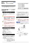
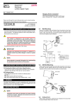
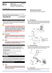
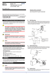
7. PART NAMES OF FRONT PANEL
9. EXPLANATION OF OPERATION
The product starts running immediately when the power is turned on;
however, it needs 10 to 15 minutes of warm-up before it meets the
specified performance.
RDY
9.1
(a) RS-232C → RS-485
Lit in green while the power is turned on
● When RS-485 Driver Active is in Auto
When start bit is detected on RS-232C side (Send Data becomes
logic 0), the converter makes RS-485 driver active, and transmits
data of RS-232C side to RS-485 side.
When Send Data of RS-232C becomes no data (logic 1), the converter starts timer of 10 bits*1 and maintains RS-485 driver active
until time-up. After time-up, the converter returns RS-485 driver
to passive to stop transmission.
● When RS-485 Driver Active is in Manual
When RS (Request to Send) of RS-232C side is turned on (logic
0), the converter makes RS-485 driver active and transmits data
of RS-232C side to RS-485 side. It maintains RS-485 driver active while RS (Request to Send) is turned on.
When RS (Request to Send) is turned off, the converter returns
RS-485 driver to passive to stop transmission.
Lit in green when data is received in
RXD of RS-232C side
SD/RD
DRIVER Lit in green while the driver is
ACTIVE active
ROTARY SWITCH
Set the switch in accordance with communication
speed.
DIP SWITCH
Set the switch in accordance with each setting.
12 3456
ON
(b) RS-485 → RS-232C
Left: OFF
Right: ON
● When start bit (logic 0) is detected on RS-485 side, the converter
turns off CS (Clear to Send) of RS-232C side and transmits data
of RS-485 side to RD (Receive Data) of RS-232C side.
When data of RS-485 side becomes logic 1, the converter starts
timer of 10 bits*1 and maintains CS (Clear to Send) of RS-232C
side off until time-up. After time-up, the converter turns on CS
(Clear to Send) to stop transmission.
*1: Equivalent to 10 bits of communication speed set to the
converter.
RS-232C CONNECTOR
D-sub 9-pin connector (male)
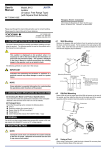
8. EXAMPLE OF USAGE
● 4-wire
9.2
RS-485
1
2
3
4
5
SDA (-)
SDB (+)
RDA (-)
RDB (+)
SG
RS-232C
(Straight
Cable)
6 8 7
RDA(-)
RDB(+)
SDA(-)
SDB(+)
SG
RS-232C → RS-485
When active control of RS-485 driver is set to Auto, RS-485 driver
is in active state for elapsed time of 10 bits after RS-232C data
becomes none. During this interim, even if RS-485 having quick
response generates signal, RS232C/RS485 converter cannot ensure transmit signal. Example of counterplan against this state is
as mentioned below:
Example 1
Set the active control of RS-485 driver to Manual. At upper computer side connected with RS-232C, make synchronization of
data transmit and RS (Request to Send). When data transmit
completes, make RS-485 driver passive immediately.
Example 2
Set the communication setting time of RS232C/RS485 converter
shorter (faster) than data transmit speed.
However, in this case, fail safe circuit should be included in every
function of RS-485 connected with this converter. (In order to
make the fail safe circuit of communication opponent recognize
the disabled state after timer cut off.)
When data from RS-485 instrument is transmitted to RS-232C,
because CS (Clear to Send) turns on during data transmission,
upper computer connected with RS-232C should incorporate
communication sequence so as to enter transmit state after receiving data up to the end.
Upper Computer
Power Supply
To other RS-485 instrument
● 2-wire
RS-485
ML2
A(-)
B(+)
SG
3 A (-)
4 B (+)
5 SG
RS-232C
(Straight
Cable)
6 8 7
Counterplan for Connections to RS-485 Instruments Having Quick Response
When starting up system or when newly adding connection of instruments, if RS-485 response is quick, communication may sometimes
not be carried out smoothly.
ML2
RDA(-)
RDB(+)
SDA(-)
SDB(+)
SG
Signal Transmit Mode (Start bit detection timer
mode)
Upper Computer
Power Supply
A(-)
B(+)
SG
To other RS-485 instrument
3
IM 77J04L02-01E
1st Edition Sep.10, 2004-00