1
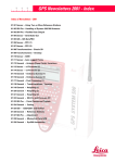
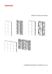
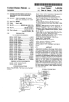
‘
US005402170A
Ulllted States Patent [19]
[11] Patent Number:
Parulski et al.
[45]
[54]
HAND-MANIPULATED ELECTRONIC
5,040,068
CAMERA TE'I'HERED To A PERSONAL
5,065,229 11/1991
Tsai et al. . . . .
COMPUTER
5,086,344
DLuna etal. ..
[75] Inventors: Kenneth A. Parulski, Rochester;
Ass1gnee:
Eastman Kodak Company,
. . . . .. 358/21 R
..... .. ass/213.15
8/1988 United Kingdom ........ .. H04N 3/15
’
~ _
_
”
User s Manual for Model 1 D1g_1ta1 Still Camera ;
Dycam, Inc., 1991.
User’s Manual-Kodak CCD 4000B Sync Camera,
Eastman Kodak Co., Apr. 1991.
[211 Appl- N0-= 938,573
[22] Filed:
Aug. 31, 1992
_
_
Primary Examiner-Howard W. Britton
Related [15- Alipllcatloll Data
Attorney, Agent, or Firm-David M. Woods
Continuation of Ser. No. 805,220, Dec. 11, 1991, abandoned.
2/1992
OTHER PUBLICATIONS
“
Rochester’ N.Y_
Mar. 28, 1995
8/1991 Parulski et al. ................... .. 358/209
0308075
Acello, East Rochester, all of NY.
_
[63]
Date of Patent:
FOREIGN PATENT DOCUMENTS
Robert H- Hamel, Walworth; John J[73]
5,402,170
6
[57]
ABSTRACT
A portable, electronic camera is connectable to a com
[51]
Int. Cl. ........................................... .. H04N 5/232
putel. for capturing an image and providing the cap_
[521
U ' S ' Cl ' """"""""""""""""""""" " 348/211'’ 348/376348/552’
tured image
to the computer for storage therewith.
The
camera ergonomically acts like an independent, self
.
[5 8] Fleld of searchl "" "
348/64’ 21 ’ 22 ’
[56]
3568/6550’ $352;
’
2’
’
5/
References Cited
functioning peripheral device while in actuality depend~
ing on instructions from the computer. The camera is
remotely linked to the computer, e. g., by a cable,
Us. PATENT DOCUMENTS
thereby allowing mobility of the camera independent of
the computer. The camera mcludes an electromc image
3,993,365 11/1976 Browne 6'1 al- 4
353/473
sensor, and circuit for driving the sensor to generate an
Barrett . . . . . . . . . . . . . . .
. . . ..
image
$133123; et a1‘
""" "
remote link. The readiness of the computer to accept an
4’714’963 12/1987 wig;
' """" "
to the computer through the
"'358/909
image signal is manifested by operative device in the
354/412
camera, which condition the camera for image capture
____ ,_ 353/256
358/335
358/210
1n response to a status s1gna1 from the computer trans
mitted through the remote hnk. In one embodiment, a
capture switch is positioned on or with the camera for
3358/903
user engagement, whereby the operative device inhibits
4:738:526 4/1988 Larish
4,751,533 6/1938 Levine
4,805,037 2/1989 Noble .
4,827,347 5/1989 Bell ............... ..
is
4,849,811 7/ 1939 Kleinerman
4,855,813 8/1989 R“Ss‘?u at al- --
358/22
gee}: """""
actuation of the capture switch until receipt of the status
signal. In another embodiment, the operative device
4:903:132 2/1990 $118322? .... .1 .
. . . . .. 358/209
energiz.“ an. exp°§ure readiness indicator when the
4,942,477
7/1990 Nakamura
.... .. ass/401
Status slgnal 1S recelved
5,019,699
5/ 1991
5,023,635
6/1991 Nealon ................................ .. 354/76
Koenck . . . . . .
. . . ..
235/472
21 Claims, 4 Drawing Sheets
LCD
VIEWFINDER
(1c
32
US. Patent
FLASH
Mar. 28, 1995
Sheet 2 0f 4
@22
5,402,170
LCD
f \42
VIEWFINDER
A
T-->
SHUTTER A26
VARIABLE
I’
K400
,28
’ APERTURE
BLUR FILTER
3G CFA
24/
FULL FRAME
>
SENSOR
\_
240
VIDEO
AMPUFIER
'
54
VIDEO
a.
30 A CLOCK DRIVERS
MD
CONVERTER
BIAS CIRCUITS
I
SENSOR
56\
DIGITAL
TIMING
CDs
BATTERY
144
'
‘6% 58
DEFECT
‘
\: DEFECT
ROM
CORRECT/0N
'
62 \ l
66 \
/35
R68
CONTROL
SHUTTER
f
64 \ l
SWITCH
SCSI
38a
\ I
INDICATOR
READY
USY
B
FAULT
—’ INTERFACE
UGHTS
1 ,38b
<
\38
'
38
6
FIG 2
-
C0IvIvECT0R
34
J
T0
l——> couguTER
US. Patent
Mar. 28, 1995
Sheet 3 of 4
5,402,170
CONNECT CAMERA CABLE
AND TURN ON COMPUTER
AND CAMERA
OPEN CAMERA ‘CAPTURE’
APPUCATION SOFTWARE
AND CHOOSE RESOLUTION.
COLOR MODE. COMPRESSION
MODE,AND MAXIMUM
NUMBER OF IMAGES.
DONE /
\
->( CAMERA ‘READY’ UGHT 0N >__> FROM
CHOOSECAMERA
OPTIONS
‘CAPTURE’
>
COMPOSE PICTURE VIA
OPTICAL V/EWFINDER AND
DEPRESS' CAPTURE‘
BUTTON o/v CAMERA TO
TAKE THE NEXT PICTURE
APPUCATION
SOFTWARE T0
ALLOW VIEWING
0F MULTIPLE
'THUMBNAIL'
IMAGES AND
DELEI'ION 0F
UNWANTED
IMAGES
IMAGE SAVED TO DISC
(FOLLOWING OPTIONAL
COMPRESSION) ‘BUSY’
LIGHT ON
CHECK IF THERE IS ROOM
YES
FOR MORE IMAGES
FIG.3
TURN ON CAMERA
‘FULL’ UGHT
US. Patent
Mar. 28, 1995
IMAGE NAME
NEWJMAGES
MAX. NUMBER OF IMAGES
Sheet 4 of 4
5,402,170
COMPRESSION
IO
MEMORY REOUIRED:
IMBYTES
MEMORY AVAILABLE:
5 MBYTES
MODE
COMPRESSION ON
C] COMPRESSION OFF
@Fi]
RESOLUTION
COLOR MODE
768 X 5/2 PIXELS
":5 24 BIT COLOR
O 384 X 256 PIXELS
D 8 BIT COLOR
C] I92 X I28 PIXELS
[3 8 BIT MONOCHROME
FIG.4
1
5,402,170
2
HAND-MANIPULATED ELECTRONIC CAMERA
ble. In one desirable application, a low cost electronic
still camera would be tethered to a small, battery oper
TETHERED TO A PERSONAL COMPUTER
ated notebook or penpad personal computer which
provides image processing, storage, and display of the
This is a continuation of application Ser. No. 805,220,
?led Dec. 11, 1990, now abandoned.
captured images. By relying on the computer to per
form these tasks, the camera cost can be greatly re
duced. In such an application, the computer would
BACKGROUND OF THE INVENTION
typically be slung over the shoulder or rested on a table,
while the user held the camera to compose the image.
1. Field of the Invention
This invention pertains to the ?eld of electronic imag 10 However, if the user must press buttons or pointers on
the computer to capture each image, as is typical in the
ing and, more particularly, to an image acquisition pe
prior art, the system will be very unwieldy to use since
ripheral operated as an input device to a personal com
the user will have to hold the camera in the right posi
puter or professional workstation.
, 2. Background Art
Video cameras and computer frame grabbers are well
known in the prior art. A typical system employs a
video motion camera (such as the CCD 4000 RGB
tion with one hand, while operating the computer with
the other hand.
By tethering the camera to the computer, as exempli
?ed by the Faulkerson et al patent, it is possible to have
both complex camera exposure functions and to control
some computer functions from the camera itself. The
as a TARGATM frame store board manufactured by 20 complex camera exposure functions remain in the cam
Flash-Sync Camera manufactured by Eastman Kodak
Co., Rochester, NY.) and a frame grabber board (such
True Vision, Inc., Indianapolis, Ind.) attached to the PC
bus of a personal computer or professional workstation.
The camera provides the timing to interface with the
video frame store board by activating the frame acquire
era, however, which is contrary to the objective of low
cost. Though it may be feasible, as done in the prior art,
to download most complex processing to the computer,
in effect slaving the camera to the computer, it is desir
line of the frame store board whenever an external 25 able to maintain the ergonomics of a hand-held camera,
voltage input to the camera is dropped low (e.g., by
dropping the “Camera Acquire In” line to the CCD
4000 camera). While the external voltage input may be
separately and directly enabled, it is customary when
using a video camera (such as the CCD 4000 camera)
with a personal computer to design software to activate
the camera’s frame acquire line from the computer. To
capture an image into the computer in such a customary
application, the operator frames the subject while ob
serving the live camera output on a video monitor, and 35
then interacts with the computer keyboard at the proper
moment. The need to use the computer keyboard fre
quently interferes with effective use of the camera.
Other known scanners that interact with a host com
puter include US. Pat. No. 4,901,364 (Faulkerson et a1)
and US. Pat. No. 4,581,761 (Ichinokawa et a1). Faulker
that is, to’ permit framing, exposure, ?ash, status indica
tion, etc., without having to interact with the host com
puter. What is needed is a design for a tethered com
puter camera and associated computer software that
allows the user to easily capture and store multiple
images from the camera into the computer disk mem
ory, without needing to interact with the computer at
the instant each image is captured.
SUMMARY OF THE INVENTION
The invention pertains to a portable, electronic cam
era connectable to a computer for capturing an image
and providing the captured image to the computer for
storage therewith. In accordance with the invention,
the camera ergonomically acts like an independent,
self-functioning peripheral device while in actuality
depending on instructions from the computer. The cam
era is linked by signal connection means to the com
puter, e.g., in one embodiment by a cable, thereby al
includes a plurality of function keys that are user-pro
grammable so as to assume certain functions that are 45 lowing mobility of the camera independent of the com
puter. The camera includes electronic image sensing
ordinarily accessed through a keyboard. For instance,
means, and means for driving the sensing means to gen
the function keys can be programmed to provide move
erate an image signal that is applied to the computer
ment from ?eld-to-?eld within a spreadsheet program
through the signal connection means. The readiness of
while entering data using the scanner, without, e.g.,
son et al describes an interactive linear scanner system
(for text) in which a hand-operated optical scanner
requiring the user to use arrow keys on the computer 50 the computer to accept an image signal is manifested by
keyboard. The camera exposure functions, however,
such as control of a light source and the enablement of
the optical scanning function, are controlled by a video
processor located in the scanner. Moreover, the image
operative means in the camera, which condition the
camera for image capture in response to a status signal
from the computer transmitted through the signal con
nection means. In one embodiment, a capture switch is
data is edited to eliminate duplicative character infor 55 positioned on or with the camera for user engagement,
whereby the operative means inhibits actuation of the
capture switch until receipt of the status signal. In an
other embodiment, the operative means energizes an
exposure readiness indicator when the status signal is
detached from a hand-operated scarmer. A switch on
the bottom of the scarmer triggers the detached proces 60 received.
mation between successive image data frames. The
edited frame data is then transmitted via data bus to a
host computer. In Ichinokawa et al, a video processor is
sor when the scanner is pushed down upon a document.
The processor then receives image data and additional
information (e.g., for switching from draw to erase,
BRIEF DESCRIPTION OF THE DRAWING
The invention will be described in relation to the
setting coordinates, and changing magni?cation) from
drawings, in which
the scanner, in turn providing processed data to a host 65
FIG. 1 is a schematic diagram of an image capture
system for a computer, including a portable, electronic
. computer.
As alluded to earlier, it is desirable to disassociate the
camera from keyboard interaction to the extent possi
camera connected to a conventional personal computer
according to the invention;
3
5,402,170
FIG. 2 is a block diagram of a preferred implementa
tion of the camera illustrated in FIG. 1;
FIG. 3 is a ?ow diagram showing the operation of the
camera of FIG. 2; and
FIG. 4 shows a typical menu selection presented to
the user by the computer.
DESCRIPTION OF THE PREFERRED
EMBODIMENTS
Referring ?rst to FIG. 1, an electronic camera 10 is
coupled to a personal computer 12 through a computer
interface 14. The camera 10 is preferably remotely
linked to the computer 12 with a cable 16, thus allowing
a certain amount of mobility for the camera 10 indepen
dent of the computer 12. The interface 14 depends on
the interface standard used; for example, if the interface
standard accommodates an analog NTSC video signal,
the interface 14 is typically a frame store board 14a,
4
to specify a minimum or maximum number of signals or
signal connections. For instance, if the camera 10 pro
vides a continuous stream of image signals, the CAP
TURE OUT line is needed to single out one image
frame for capture by the computer 12. Of course, de
pending upon the embodiment, this could be a separate
signal (CAPTURE OUT) or it could be, e.g., a bit set in
a header that travels with the image signal (IMAGE
OUT). In the latter case, a separate CAPTURE OUT
signal is unnecessary. If the camera 10 provides a single
still-image signal (rather than a stream of image signals),
the mere existence of an image signal on the IMAGE
OUT line is determinative of the captured image. In that
case, there is no need to communicate a separate CAP
TURE OUT signal to single out a particular image
instance; if the Small Computer System Interface
frame.
A status signal on the CONTROL IN line controls
usage of the shutter release 36 such that the shutter
release 36only activates a still capture, or pulses the
CAPTURE OUT line, when the status signal is set.
Several alternatives are possible: the status signal could
(SCSI) is used, the interface 14 is a SCSI interface board
14b. The choice of interface, as will be shown, deter
the shutter release 36 will have no effect until the lamp
mines the type of signal processing employed in the
38 is extinguished (i.e., continued depression of the
such as the aforementioned TARGA TM board. Alter
natively, a digital interface standard may be used; for
illuminate the indicator lamp 38, passively showing that
camera 10. The computer 12 additionally includes a 25 shutter release 36 would not be recognized by the com
conventional keyboard 18 and a conventional disk drive
puter 12). Alternatively, the status signal could actively
20, the latter being used to store pictures captured by
inhibit the shutter release 36, e.g., by preventing the
the camera 10. Although not shown, the computer 12
generation of a CAPTURE OUT signal or the initiation
of a still exposure. Moreover, the CONTROL IN line
includes the usual RAM storage for buffering incoming
image data.
The camera 10 includes an optical system, repre
sented by the lens 22, for directing image light from an
may have separate status signals for enabling the shutter
release 36 and illuminating the lamp 38, or if the two
states are mutually exclusive, the two conditions of a
single binary status signal may manifest both states.
Furthermore, in a preferred implementation, the CON
optionally include, in certain embodiments, a shutter 26
and a diaphragm 28 for regulating the quantity of image 35 TROL IN line includes several status components for
illuminating several different status indicator lamps.
light exposed upon the image sensor 24. The sensor 24
object to an image sensor 24. The optical system may
is biased and driven by a sensor clock generator 30,
which provides the signals used to clock an output
image signal from the sensor 24. The output image sig
nal is applied to a signal processor/controller 32, the
complexity and type of processing and control varying
In one implementation of the invention, the sensor 24
is a scan rate video sensor producing a motion video
signal and the signal processor/controller 32 includes a
stage for converting the image signal into an analog
NTSC video signal, which is transmitted through the
connector 34 to the computer 12 as the IMAGE OUT
signal. Typically the interface 14in such an application
processor 32 exits the camera through a connector 34,
is a framestore board 14a. In the implementation just
which accepts a suitable connector (not shown) on the
cable 16. The camera 10 further includes a shutter but 45 mentioned, actuation of the shutter switch 36 pulses the
according to the embodiment. The output of the signal
ton 36 for initiating either an exposure sequence or a
CAPTURE OUT line, which is connected through the
frame capture, depending upon the embodiment; a sta
tus indicator 38, which may include a liquid crystal
connector 34 to, e.g., the capture control line of the
framestore board 140. The framestore board 14a then
captures a frame from the continuous video signal out
put on the IMAGE OUT line. An appropriate signal on
display (LCD) panel or a plurality of indicator lamps
for indicating the status of the computer 12 to the user
the CONTROL IN line to the signal processor/con
(that is, “ready” for another picture, or “busy” process
troller 32 activates the shutter button 36, that is, allows
ing the just-taken picture) a view?nder 40, which may
the signal processor/controller 32 to output a capture
be an optical view?nder (as represented by the lens 40a,
pulse on the CAPTURE OUT line; likewise, appropri
40b) or an electronic view?nder (as represented by the
LCD display 40c connected by broken line 40d to the 55 ate signals on the CONTROL IN line energize appro
priate indicator lights 38 to tell the user the status of the
signal processor/controller 32); an electronic ?ash 42,
computer 12, that is, whether the computer 12 is ready
which may be detachable or integrally formed with the
to capture the next image, whether it is in the process of
camera; and a power supply 44 for powering the vari
storing the present image to the disk drive 30, or
ous circuits and electrically-powered components in the
camera 10.
whether the drive 20 is full.
For purposes of broadly describing the functions of
the camera 10, the signal processor/controller 32 is
is shown in FIG. 2 in block diagram form wherein
shown as outputting CAPTURE OUT and IMAGE
identical reference characters are used to identify com
A second, preferred implementation of the invention,
ponents similar to those described in FIG. 1. In this
OUT signals to the computer 12. In particular, the pro
cessor/controller 32 is operative to condition the cam 65 implementation the signal processor/controller 32 gen
erates a digital color image signal for application
era for image capture in response to a CONTROL IN
through the connector 34 to the SCSI interface board
signal received from the computer 12. These signals are
14b (shown in FIG. 1). A still image signal is generated
exemplary of the supported functions and are not meant
5
5,402,170
6
by the image sensor 24, which in this embodiment in
porated herein by reference.) The user also speci?es the
cludes a full-frame sensor 24a, such as the Model KAF
image group name and the maximum number of images
to be saved. The computer then calculates the required
storage space to determine if the required amount of
0400 (768x 512 pixels) manufactured by Eastman
Kodak Company, and a “3-Green” color ?lter array
24b. The principle of the “3-green” color ?lter pattern,
disk memory is sufficient. Once the selections are made,
the camera “ready” lamp 38a is lit, and the user can
along with the concomitant use of a blur ?lter 50, such
as a birefringent optical ?lter, is described in US. Pat.
close the computer (if required) and sling it over the
No. 4,663,661, “Single Sensor Color Video Camera
with Blurring Filter” which is assigned to the same
assignee as the present application and incorporated
herein by reference. The signal processor/controller 32
includes a video ampli?er 52, which applies an ampli
?ed video signal to a video analog/digital (A/D) con
verter 54. Sampling noise is removed from the digital
video signal in a digital correlated double sampling
circuit 56. (A suitable digital sampling circuit 56 is dis
closed in Ser. No. 522,030, ?led May 11, 1990, entitled
“Digital Correlated Double Sampling Circuit for Sam
pling the Output of an Image Sensor”, which is an al
lowed application assigned to the same assignee as the
shoulder while holding the camera.
The user frames the image and depresses the capture
button 36. This begins a sequence which ?res the flash
42 if required, actuates the shutter 26, and reads the
digitized image sensor data, a line at a time, over the
SCSI bus (connection 16) to the computer RAM mem
ory. Depending on the capture options selected, the
data is either stored directly from RAM to the hard disc
20 (or other non-volatile computer memory), is com
pressed using, e.g., the aforementioned known image
compression method, etc. The ?rst image is stored as
image group name 1, and subsequent images are stored
as image group name 2, image group name 3, etc. While
present application and incorporated herein by refer
this happens, the computer turns off the “ready” lamp
ence.) Imager defects are corrected in a defect correc
tion stage 58 (the actual defect locations are stored in a
defect ROM 60). Red, green, and blue look up tables
(LUTs) 62 are provided for gamma correction and
white balance. The output signals are converted to the
SCSI standard by a SCSI interface 64 and transmitted
through the connector 34 to the SCSI interface board
14b in the computer 12.
A programmed microprocessor-driven controller 66
provides the commands, instructions, and signals neces
38a and illuminates the “busy” lamp 38b, so the user
knows that the computer operations are occurring,
without having to look at the computer display screen.
Assuming that the current image number is less than the
maximum number of images so that there is room to
store more images (and that the flash has recharged if
required), the “ready” lamp 380 is illuminated so that
30
sary to operate the camera, in particular responding to
control inputs from the computer 12 through the SCSI
interface 64 to initiate a still exposure sequence subject
to actuation of the shutter switch 36. In other words,
the controller 66 waits for instructions from the com
puter 12 before recognizing an input from the shutter
switch 36. During the interim, indicator lamps 38a, 38b,
38c are illuminated to indicate the condition of the cam
era 10 relative to the computer 12. The indicator lamps
are illuminated by a signal from the controller 66 pursu
ant either to speci?c instructions from the computer 12
or, particularly if only one lamp is used, by the absence
the user knows that the next image may be framed and
captured. If the disk drive 20 (or other storage device)
is full, or other problems are noted, then the “fault”
lamp 38c is illuminated. The user then proceeds to sub
stitute another disk (if drive 20 uses removable media),
move or delete some images, or otherwise correct the
problem, and the “ready” lamp 38a is again illuminated.
If the storage medium is ?lled, a mosaic of small,
“thumbnail” images may be produced on a single screen
image of the computer’s monitor to facilitate choice of
unwanted images.
The invention has been described in detail with par
ticular reference to a presently preferred embodiment,
but it will be understood that variations and modi?ca
tions can be effected within the spirit and scope of the
of an enable signal for the shutter switch 36.
The camera shown in block form in FIG. 2 is particu 45 invention. For instance, while analog and SCSI inter
faces have been described, it is also feasible to use the
larly adapted for connection through a digital interface,
parallel
and serial ports conventionally available on a
such as a SCSI interface, to a small light-weight com
personal computer.
puter, such as a laptop computer with an LCD display
What is claimed is:
and a large capacity hard disk drive. With that utility in
mind, the operation of the camera of FIG. 2 is described 50 1. A portable, electronic camera connectable to a
computer for capturing an image and providing the
in the self-explanatory ?ow-chart shown in FIG. 3. The
captured image to the computer for storage therewith,
user begins by connecting the camera 10 to the com
said camera comprising:
puter 12 and turning on the power supply 44. The user
signal connection means for linking the camera to the
opens a “tethered camera” application program in the
computer;
computer 12 and selects capture parameters from a 55
means for sensing an image;
menu shown in FIG. 4. The options can include the
means for driving said sensing means to generate an
color mode (8 or 24 bit color or monochrome images),
image signal corresponding to the image, and for
storing the full resolution images or lower resolution
subsampled images (e.g. allowing the user the choice of
full resolution (e.g., 512x768 pixel) images or lower 60
resolution (e.g., 256>< 384, or 128x192 pixel) images,
i.e., thereby using lower resolution to allow more im
ages to be stored in the memory), storing compressed or
uncompressed images, and so on. (A suitable image
compression technique for images from a “3-green” 65
color image sensor is disclosed in US. Pat. No.
5,065,229, “Compression Method and Apparatus for
Single-Sensor Color Imaging Systems”, which is incor
applying the image signal to said signal connection
means for transmission to the computer;
operative means for conditioning the camera for
image capture in response to the readiness of the
computer for accepting an image signal, said opera
tive means responsive to a status signal from the
computer transmitted through said signal connec
tion means, whereby the computer is adapted for
storage of the image signal after providing the
status signal; and
7
5,402,170
image signal corresponding to the image, and for
applying the image signal to said signal connection
signal, thereby capturing an image, and wherein
said operative means inhibits actuation of said ex
posure release means until receipt of said status 5
signal indicates that the computer is ready to re
ceive the image signal.
2. A camera as claimed in claim 1 wherein the camera
further comprises a capture switch for outputting a
accepting an image signal, said indicating means
responsive to a status signal from the computer
transmitted through said signal connection means;
and
signal for initiating the capture of an image signal
corresponding to a selected image, whereby the
computer initiates storage of the image signal after
providing the status signal and receiving the cap
a still image in response to the occurrence of the capture
command signal and the receipt of the status signal from
the computer.
3. A camera as claimed in claim 1 wherein the camera 15
further comprises an exposure readiness indicator and
ture command signal.
12. A camera as claimed in claim 11 for use with a
computer including a framestore capture circuit having
a capture input for actuating the capture of an image,
wherein said operative means energizes said exposure
readiness indicator when said status signal indicates that
the computer is ready to receive the image signal.
and wherein;
4. 'A camera as claimed in claim 3 wherein said expo 20
sure readiness indicator has a plurality of indicator
states and wherein the status signal has a plurality of
components each actuating a corresponding one of said
indicator states to show that the computer is ready to
said driving means generates a series of image signals
corresponding to a series of images; and
the capture command signal output by said capture
switch is applied to the capture input of the frames
tore capture circuit in order to initiate the capture
of a particular image signal.
receive an image signal, that the computer is busy pro
cessing an image signal, and that a storage device in the
computer is full.
13. A camera as claimed in claim 11 wherein said
readiness indicating means toggles between two states
indicating whether or not the computer is ready to
5. A camera as claimed in claim 1 wherein the image
accept an image signal, and wherein said capture switch
signal generated by said driving means comprises a
is rendered effective in outputting a capture command
stream of image signals corresponding to a stream of
consecutive images, and wherein the camera further
comprises a capture switch for outputting a capture
command signal to the computer to identify an image
signal after said readiness indicating means has changed
to the state indicating that the computer is ready to
accept an image signal.
14. A camera as claimed in claim 11 further including
35
6. A camera as claimed in claim 5 for use with a
a cable interface connecting said signal connection
means with the computer whereby the camera remains
tethered to the computer.
computer including a framestore capture circuit having
a capture input for initiating the capture of an image,
and wherein;
the capture command signal output by said capture
switch is applied to the capture input of the frames
15. A portable electronic camera connectable to a
computer through a peripheral interface for capturing
an image and providing the captured image over the
interface for storage with the computer, said camera
tore capture circuit in order to initiate the capture
comprising:
of a particular image signal.
means for sensing an image and generating an image
7. A camera as claimed in claim 1 wherein speci?c
image capture options are speci?ed through interaction
signal;
45
with the computer, and wherein said driving means
outputs a common image signal that is subsequently
con?gured in the computer according to the speci?ed
capture options.
an interface controller for controlling the transmis
sion of data between the camera and the computer;
a capture switch for generating a capture signal that
initiates a still exposure;
means responsive to (a) a control signal from the
8. A camera as claimed in claim 7 wherein the speci?c
image capture options are used for a multiplicity of
images.
means for transmission to the computer;
means for indicating the readiness of the computer for
a capture switch for outputting a capture command
capture command signal, and wherein said driving
means generates a single image signal corresponding to
signal selected from the stream of image signals.
8
means for driving said sensing means to generate an
exposure release mean connected to said driving
means for initiating the generation of an image
_
9. A camera as claimed in claim 7 wherein said image
capture options include storage of either a full resolu
tion image or a subsampled image.
55
10. A camera as claimed in claim 7 wherein said sens
ing means includes a color ?lter array for generating
color-responsive signals and said image capture options
include storage of either a color or a monochrome im
age.
computer transmitted through the interface con
troller for enabling said sensing means to generate
a still image signal and (b) actuation of said capture
switch for triggering the enabled sensing means to
capture a desired still image; and
status indicator means responsive to a status signal
from the computer transmitted through the inter
face controller for indicating when the computer is
ready to accept a still image signal.
16. A camera as claimed in claim 15 wherein said
status signal is included with said control signal.
11. A portable, electronic camera connectable to a
17. A portable, electronic camera connectable to a
computer for capturing an image and providing the
captured image to the computer for storage therewith,
computer for capturing an image according to image
said camera comprising:
capture options speci?ed by the computer and provid—
ing the captured image to the computer for storage
signal connection means for remotely linking the 65 therewith, said camera comprising:
signal connection means for remotely attaching the
camera to the computer, thereby allowing mobility
camera to the computer and thereby allowing mo
of the camera independent of the computer;
bility of the camera independent of the computer;
means for sensing an image;
9
5,402,170
10
for applying the image signal to said signal con
means for sensing an image;
means for driving said sensing means to generate an
nection means for transmission to the computer;
image signal corresponding to the image regardless
of speci?ed image capture options, and applying
and
4) operative means for conditioning the camera for
image capture in response to the readiness of the
said image signal to said signal connection means;
a view?nder for viewing a plurality of images in
order to select a desired image; and
a capture switch for initiating the capture of an image
signal and transmission thereof to the computer
through said signal connection means, whereby the 10
computer processes the desired image according to
computer for accepting an image signal, said
operative means responsive to a status signal
from the computer transmitted through said
signal connection means, whereby the computer
is adapted for storage of the image signal after
providing the status signal; and
b) a computer connectable to the camera for storing
the speci?ed capture options after receipt of the
capture command signal.
the image according to speci?ed options dependent
upon processing of the image signal, said computer
18. A camera as claimed in claim 17 wherein said
capture options include the choice of either full resolu 15
tion or subsampled resolution, or color or monochrome
comprising:
1) an image compression algorithm providing at
least one mode of compression;
reproduction.
19. A system including a camera and a computer for
capturing a still electronic image, said system compris
20
g:
a) a portable camera connectable to the computer for
capturing the image and providing the captured
image to the computer for storage therewith, said
2) means for selecting a speci?c image processing
option, including the mode of compression, the
resolution of the captured image as derived from
the image signal, and the processing of color or
monochrome images from the image signal; and
3) means for generating and transmitting the status
signal to the camera.
camera comprising:
20. A system as claimed in claim 19 wherein the speci
1) signal connection means for linking the camera 25
?ed image processing options include application of the
to the computer;
2) means for sensing an image, said sensing means
having a maximum resolution and being capable
of producing a color output;
3) means for driving said sensing means to generate
an image signal corresponding to the image, and
speci?ed options to a plurality of images.
21. A system as claimed in claim 19 wherein the speci
30
?ed image processing options include the ability to limit
the maximum number of captured images.
*
35
45
50
55
60
65
*
*
*
*