1
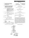
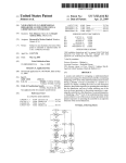
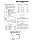
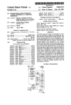
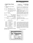
USO0RE41524E
(19) United States
(12) Reissued Patent
(10) Patent Number:
US
(45) Date of Reissued Patent:
Parulski et al.
(54)
ELECTRONIC STILL CAMERA FOR
FOREIGN PATENT DOCUMENTS
CAPTURING AND CATEGORIZING IMAGES
(75) Inventors: Kenneth A. Parulski, Rochester, NY
(US); Thomas A. Napoli, Rochester, NY
(US); David M. Lewis, Phoenix, AZ
EP
0 640 938 A2
EP
JP
640938 A2 * 3/1995
5-044460
* 12/1993
JP
5-344460
User’s Manual (excerpts). Eastman Kodak Company, 1991,
NY (US)
Filed:
1992*
“TIFF/EP, A Flexible Image Format for Electronic Still
09/313,535
May 13, 1999
Cameras”, by Ken Parulski and George Lathrop, Eastman
Kodak Company, Rochester, NY. Preprint from IS&T’s 48th
Annual Conference, May 1995*
Operation and Maintenance Manual for the Kodak HaWkeye
II Imaging Accessory, Part 6364101, Catalogue No. 144
Related US. Patent Documents
Reissue of:
(64)
Patent No.:
Appl. No.:
5,633,678
May 27, 1997
08/574,756
Filed:
Dec. 20, 1995
Issued:
(51)
12/1993
Kodak Professional Digital Camera System (DSC 100)
(73) Assignee: Eastman Kodak Company, Rochester,
Appl. No .:
8/1994
OTHER PUBLICATIONS
(Us)
(21)
(22)
RE41,524 E
Aug. 17, 2010
7903. Eastman Kodak Company, Federal Systems Divi
sion.*
* cited by examiner
Primary ExamineriQuochien B Vuong
Int. Cl.
H04N 5/76
(74) Attorney, Agent, or FirmiDavid M. Woods
(2006.01)
(57)
ABSTRACT
(52)
US. Cl. ............................. .. 348/231.5; 348/207.11;
(58)
Field of Classi?cation Search ........... .. 348/207.99,
of subjects and categorizes the image according to subject
348/207.1, 207.11, 222.1, 231.99, 231.1,
348/231.2, 231.3, 231.5, 231.7, 239, 552;
matter. The camera comprises an image sensor for capturing
an image, a converter stage for converting the image into
348/231.2; 348/239; 348/552
An electronic camera captures images representing a variety
digital image data, and a memory for storing a plurality of
H04N 5/30, 5/225
categories providing classi?cation of the images by subject.
See application ?le for complete search history.
A processor in the camera has the capability of assigning the
References Cited
plurality of categories to the images captured by the camera,
U.S. PATENT DOCUMENTS
images. A user selects one or more categories for a plurality
(56)
With each category providing a subject classi?cation for the
of images prior to capture, and an output image signal is then
generated including the digital image data Corresponding tO
4,524,381 A : 6/1985 Konishi ..................... .. 386/38
4,574,319 A *
3/1986 Konlshl ................. .. 348/2316
i *
233:5?‘ e211‘
"
a Captured image and the particular Category Selected by the
;
user. The categories can be default identi?ers stored in the
5’l53’729 A * “M992 sgistolet '
" 3480316
5’335’072 A * 8/1994 Tanaké'l'é't't'li "" "
" 3480313
5’477’264 A * 0/1995 Sarbadhikar'i """"" " 348/23'l
memory, or canbe names, text (i.e.,accountnumber), and/or
graphics overlays (1.e., company logo) entered via a host
computer and uploaded to the camera memory before the
5,502,486
A
*
3/1996
Ueda et a1.
Plcmresaretaken'
5,515,101
A
*
5/1996
Yoshida
5,796,428 A
*
8/1998 Matsumoto et a1. ....... .. 348/231
......
. . . .. 348/239
. . . . . . . . . . . . .
. . . ..
348/232
26 Claims, 6 Drawing Sheets
INPUT SECTION (A)
COMPRESSION AND RECORDING
SECTION (B)
'5 [IMAGE BUFFER I/IB
'
5:378‘???
sled/12f
2s
TI pnocesson
l2
2
,o/
Z2
r
|
' FRAME! t
f”
I /30a
28
I
/
"" """ _'
FLASH
UNIT
I
2%
t
t#____ PROCESSOR
|||| m1
PROCESSING
24'’
ALGORITHMS
200 1
I
[E],/
BEE/M51’
__.
'9
1. s
SHUTTER
BUTTON ‘2|
>-~
STATUS
4
35"
‘u
.4
'“
—_-
FIRMWARE
31/ : MEMORY
J24
g2; 12,.
_“
DISPLAY
.__50
13E
2"; 29
m
_
RAM
ya?”
*1 “55%?” f
US. Patent
Aug. 17, 2010
525‘
Sheet 3 of6
/ 50 PI
5,2."
>-
"a
-
X?
E AAA?! I535"?! II?! If‘? "
£1
"
528"’
US RE41,524 E
52a
15E’; 5Q?” 5%; iijyi
/
1
5
54
55b
F I G. 3
/so
usER TURNS o~ cAMERA
/6,
PHS‘QgJQAiZw
GROUP ?
USER SELECTS APPROPRIATE
CATEGORY ICON AND
CHOOSES DESIRED CATEGORY
USER CONNECTS CAMERA
I
.
62
_
OR MEMORY CARD To
/
THE HOST coMPuTER
usER TAKES PIcTuRE BY
DEPRESSING SHUTTER BUTTON
/
65\
usER OPENS cAMERA
APPLICATION AND CHOOSES
oEsIREo cATEeoRIIEsI
63
IMAGE ISWISTLOIEEQESIOEILE ALONG
CHOSEN BY THE USER
YES
MORE
IMAGES FoR, THIS \NO
66 \
IMAGES FROM APPROPRIATE
CATEGORIES ARE DOWNLOADED
To PROPER FOLDERS
ACCORDING To THE CATEGORY
IN EACH IMAGE FILE
CATE?GORY
F164
US. Patent
Aug. 17, 2010
US RE41,524 E
Sheet 4 0f 6
USER INPUTS CATEGORIES, AND
RELATED TEXT/ GRAPHICS ON HOST
~70
USER DOWNLOADS CATEGORIES/TEXT/GRAPHICS
TO CAMERA USING CABLE OR MEMORY CARD
USER TURNS ON CAMERA
USER SELECTS APPROPRIATE CATEGORY ICON
AND CHOOSES DESIRED CATEGORY
'
YES
I
_
usER. TAKES PICTURE BY
-/74
OEPREssING sHUTTER BUTTON
75
ANOTHER
PHOTOGRAPHIC
T
/
As IMAGE IS PROCESSED, OPTIONAL TExT
GROUP _P
/
GRAPHICS ANO/OR DATE TIME IS
OVERLAYED INTO IMAGE IF ENABLED FOR
THE CATEGORY CHOSEN BY UsER
NO
I
/ 76
IMAGE IS sTOREO IN FILE ALONG wITH CATEGORY
NAME AND OPTIONAL TExT FOR THE CATEGORY
CHOSEN BY THE USER
YES/ MORE IMAGEs FO
THIS CATEGORY
NO
64
usER CONNECTS CAMERA OR MEMORY
CARD TO THE HOsT COMPUTER
USER OPENS CAMERA APPLICATION AND I
CHOOSES DESIRED CATEGORIIESI
FIG. 5
66\
IMAGES FROM APPROPRIATE CATEGORIES ARE ‘
DOWNLOADED T0 PROPER FOLDERS ACCORDING
TO THE CATEGORY NAME IN EACH IMAGE FILE
US. Patent
Aug. 17, 2010
Sheet 6 of6
US RE41,524 E
STORED IMAGE m;
SELECTED CATEGORY H23
H
CAPTURED
IMAGE
CLAIM #|23 --LT____>
+
GRAPHIC
Fly-by-night M N019, 1995
Insurance Co.
/
W115 0m
Cluim #IZZ»
DATE/TIME
F168
DATE
50/
ON
OFF
TIME
ON
OFF
TEXT
ON
OFF
56
0’,
,29
f
54
US RE41,524 E
1
2
The Kodak Professional Digital Camera System (model
ELECTRONIC STILL CAMERA FOR
CAPTURING AND CATEGORIZING IMAGES
DCS-100) included a digital camera tethered by cable to a
separate digital storage unit (DSU). The DSU, similar to the
computer 4 of FIG. 1, contained a hard drive for storing
Matter enclosed in heavy brackets [ ] appears in the
original patent but forms no part of this reissue speci?ca
images, a small image display, and a keypad for manipulat
ing the images. For images that had already been captured by
tion; matter printed in italics indicates the additions
made by reissue.
the camera, the system included a “tag” feature that allowed
a user to ?ag selected images for later display or for upload
ing from the DSU to another computer. Suppose that a user
FIELD OF THE INVENTION
wanted to tag a couple of already-captured images for later
viewing or uploading. The ?rst of the images would be
brought up on the display and a “tag” button on the keypad
This invention pertains to the ?eld of electronic imaging
systems, and in particular to a digital electronic still camera
of the type that is used with a host computer.
would be pressed, and so on with the other images that are to
be tagged. Then if the user presses a “?nd tags” key on the
BACKGROUND OF THE INVENTION
keypad, the ?rst of the tagged images is displayed (and/or
As understood in the prior art, a digital electronic still
uploaded). With a second press of the “?nd tags” key, the
camera is a device which uses an electronic sensor to capture
second tagged image is displayed (and/or uploaded), and so
an image; signal processing to represent the captured signal
numerically; and some storage device to preserve the
numerical image data. It is further known for a digital elec
on.
Another embodiment of this camera, the Kodak Hawkeye
20
tronic still camera to use a removable storage device, such as
image after the image was taken, and to add a “note” text
string to the image ?le. Both cameras allowed a simple divi
an integrated circuit memory card, to store images. For
instance, US. Pat. No. 5,016,107 describes an electronic still
sion of already-captured images into “tagged” and “not
tagged” images and required a pattern of keystrokes
camera utilizing image compression and providing digital
storage in a removable memory card having a static random
access memory. In this camera, the integrated circuits in the
removable memory card store image data and a directory
25
dling. Anything more complex in the way of data organiza
Coordination between a digital camera and a computer is
tion requires, as shown in FIG. 1, the use of a special
30
electronic still photography system useful for inputting
images to a computer. The system includes an electronic
camera 1 with an electronic sensing section 1a, a digital
processing section 1b, a memory card slot 2, and a remov
able memory card 3; and a host computer 4 with a built-in
memory card reader 5, a printer 6a, a display 6b, a keyboard
data entry device 7 and a disk drive 8. Images are captured
by the sensing section 1a in the camera 1, manipulated in the
processing section 1b, stored on the memory card 3, and
transferred from the card 3 to the host computer 4. The soft
ware used to control the sensing and processing sections 1a
and 1b in the camera is located in ?rmware memory 10 in the
camera 1. The application software used to control the play
back operations of the host computer is supplied, at least in
part, by the camera manufacturer. For instance, the manufac
35
SUMMARY OF THE INVENTION
The present invention is directed to overcoming one or
more of the problems set forth above. Brie?y summarized,
according to one aspect of the present invention, an elec
tronic camera captures images representing a variety of sub
40
jects and categorizes the image according to subject matter.
The camera comprises an image sensor for the images, a
converter stage for converting the images into digital image
data, and a memory for storing a plurality of categories pro
viding classi?cation of the images by subject. A processor in
45
the camera has the capability of assigning the plurality of
categories to the images captured by the camera, with each
category providing subject classi?cation of one or more
images. A user then interacts with a user control on the cam
era in order to select one or more of the categories for the
50
images, and an output image signal is then generated includ
ing the digital image data corresponding to the images and
the one or more categories selected by the user control.
are stored as sequentially numbered images, it can be di?i
cult and time consuming to locate a group of images of
interest from all of the images stored in the camera. In a
typical usage, an insurance adjuster may take a number of
photos in processing a number of different claims during one
day’s operations. It would be desirable to be able to identify
the images of each group, for example by claim number or
application program in the host computer 4 to organize and
sort the image data. Consequently, it would be desirable to
have an electronic still system that could handle image con
tent more ef?ciently in the ?eld than is presently the case.
turer may provide a special disk or memory card that comes
with the camera. The application software is transferred to
the computer hard drive 8, and then downloaded to a com
puter random access memory (RAM) memory 9a, where the
program is used by a central processing unit (CPU) 9b.
Digital cameras, such as the Kodak Digital Science
DC40TM camera sold by Eastman Kodak Company, allow
almost a hundred images to be stored. Because the images
subsequent to capture for every image of interest. In
particular, the tagging feature functioned more as a post
capture data gatekeeper than as a useful tool for image han
locating the data.
generally known in the prior art. FIG. 1 shows a known
II camera, also allowed the user to type in a name for any one
55
The advantage of the invention is that the known provi
sion of a simple post-capture “tag” is enlarged into useful
pre-capture categories that can effectively manage images
according to variable subject content. According to this
invention, a digital camera includes a display-based “tag”
icon/feature which the user can set to an appropriate cat
egory before taking a group of pictures. The category names
60
can be defaults, or can be names and optional text (i.e.,
account number) and/or graphics overlays (i.e., company
client name. It may be further desirable to allow this
information, along with the date and time or a company
logo) entered via a host computer and uploaded to the cam
logo, to be optionally included with the image data. This
era before the pictures are taken. When the user selects a
ensures that any prints made from the camera can be easily
particular category, the category name is stored along with
the image data in the image ?le, and any text and graphics
identi?ed. Such processing of the captured images is today
performed in a ho st computer, such as the ho st computer 4 in
FIG. 1.
65
logo, as appropriate, are overlaid onto the image. When
downloading the images to a host computer, the user can
US RE41,524 E
3
4
select a category and download only the images Which have
log image charge information corresponding to the particu
lar image is generated in respective photosites. The charge
a particular category name, or the images can be stored in
folders labeled With each category name.
information is applied to an output diode 14, Which converts
the charge information to analog image signals correspond
ing to respective picture elements of the particular image
These and other aspects, objects, features and advantages
of the present invention Will be more clearly understood and
appreciated from a revieW of the folloWing detailed descrip
tion of the preferred embodiments and appended claims, and
captured.
The analog image signals are applied to an A/D converter
16, Which generates digital image data from the analog input
signals for each picture element. The digital image data is
by reference to the accompanying draWings.
BRIEF DESCRIPTION OF THE DRAWINGS
applied to an image buffer 18 for storing one or more
images, albeit shoWn in FIG. 2 as a random access memory
FIG. 1 is a diagram of a knoWn electronic imaging system
incorporating a digital camera for inputting images to a host
(RAM) With storage capacity for a plurality of still images.
A programmed control processor 20 generally controls the
input section A of the camera by initiating and controlling
computer.
exposure (by operation of the diaphragm and shutter (not
shoWn) in the exposure section 10), by controlling the ?ash
unit 11, by generating the horizontal and vertical clocks
FIG. 2 is a block diagram of an electronic camera con?g
ured according to the invention to process and categorize
images.
FIG. 3 is a diagram of the status display panel and the user
control sWitches used in the camera shoWn in FIG. 2.
FIG. 4 is a process diagram for categorizing images
20
according to default parameters stored in the camera shoWn
in FIG. 2.
Would typically be effected by using ambient light informa
FIG. 5 is a process diagram for categorizing images
according to externally generated parameters supplied to the
camera shoWn in FIG. 2.
25
Once a certain amount of digital image data has accumu
lated in the image buffer 18, the stored data is applied to a
30
FIG. 9 is an additional diagram of the status display panel
35
sion algorithms, such as the Well-known JPEG (Joint Photo
DETAILED DESCRIPTION OF THE INVENTION
40
Because electronic still cameras employing electronic
sensors are Well knoWn, the present description Will be
directed in particular to elements forming part of, or cooper
sion is shoWn in the camera of FIG. 2, compression is not a
ating more directly With, apparatus in accordance With the
the removable storage device is a memory card 24. While a
memory card 24 is shoWn in this system as the storage
device, other devices may be used, such as a ?oppy disk
magnetic medium, a small hard drive, or optical storage (in
50
in such arts.
FIG. 2 shoWs an electronic still camera capable of catego
the latter cases, suitable conventional reading/Writing appa
ratus Would be provided in the camera, e.g., magnetic or
optical read/Write head, etc.). A representative memory card
is a card adapted to the PCMCIA card interface standard,
such as described in the PC Card Standard, Release 2.0,
rizing images as taught by the invention. The electronic still
camera is divided generally into an input section A and a
55
published by The Personal Computer Memory Card Intema
tional Association, Sunnyvale, Calif., September 1991. The
memory card 24 accordingly contains solid state memory
24a, such as Flash EPROM memory, Which the card uses to
not shoWn, the exposure section 10 includes conventional
optics for directing the image light through a diaphragm,
compression algorithm from the memory 28 to the digital
image data, and sends the compressed data to a removable
storage device via a signal port 26. HoWever, While compres
necessary feature, and uncompressed data could be stored
instead in the removable storage device.
In this example, the signal port 26 is a card interface and
present invention. Elements not speci?cally shoWn or
described herein may be selected from those knoWn in the
art. Certain aspects of the embodiments to be described are
compression and recording section B. The input section A
includes an exposure section 10 for directing image light
from a subject (not shoWn) toWard an image sensor 12. A
?ash unit 11 may be used to illuminate the subject. Although
according to any one of a number of knoWn image compres
graphic Experts Group) discrete cosine transformation
based compression algorithm. The processor 22 applies the
ture using categories.
provided in softWare. Given the system description as
described in the folloWing materials, all such softWare
implementation is conventional and Within the ordinary skill
programmed digital signal processor 22, Which controls the
throughput processing rate for the compression and record
ing section B of the camera. The algorithms and other oper
ating code used by the processor 22 are stored in an algo
rithm memory 28. The digital signal processor 22
compresses each still image stored in the image buffer 18
FIG. 8 is an example of an image display With customized
category information overlaid into the image.
and the user control sWitches set up for activating an overlay
feature.
FIG. 10 is an example of an image ?le management struc
tion from a photocell 19, and a shutter button 21 alloWs the
user to initiate a capture cycle. The processor 20 also
receives date and time information from a date/time genera
tor 20a.
FIG. 6 is an example of categories that are customized
from a host computer.
FIG. 7 is an example of a ?le format resulting from cus
tomized categories.
needed for driving the sensor 12 and for clocking image
information therefrom, and by enabling the A/D converter
16 in conjunction With the image buffer 18 for each signal
segment relating to a picture element. Exposure control
60
store image data ?les.
According to this invention, the digital camera includes a
Which regulates the optical aperture, and a shutter, Which
categorization feature Which enables a user to establish an
regulates exposure time. The sensor 12, Which includes a
appropriate category, providing classi?cation of the images
by subject, before taking a group of pictures. The category
tWo-dimensional array of photosites corresponding to pic
ture elements of the image, is a conventional charge-coupled
device (CCD) using, e.g., either Well-known interline trans
fer or frame transfer techniques. The sensor 12 is exposed to
image light to capture a particular image; accordingly, ana
65
information can be default code symbols (A,B,C, etc.), or
can be extemally-generated category information, such as
names and optional text (i.e., account numbers) and/or
graphics overlays (i.e., company logos), Which is entered via
US RE41,524 E
5
6
a host computer and uploaded to the camera through the
signal port 26 before the pictures are taken or via cable con
nection. After the user selects a particular category, the
image delete icon 52f.) The user control sWitches 29 include
a toggle sWitch 54 and a select button 56. The toggle sWitch
54 is used to toggle to a setting once an icon has been acti
image is captured and the category information is stored in
the removable storage device along With the image data in
the image ?le, and any text and graphics logo, as
appropriate, are overlaid onto the image. When doWnloading
vated by the select button 56. For example, if the ?ash mode
icon 52d is highlighted and shoWing that it is the currently
active control, pressing the select button Would activate the
tag icon 52a and make it the currently active control.
While not important to this invention, other information
the images to a host computer, the user can select a particular
displayed on the status display 30 might include typical pho
tographic data, such as shutter speed, aperture, exposure
category and doWnload only the images Which have a par
ticular category identi?er, or the images can all be doWn
loaded and stored in ?le folders labeled With each category
bias, color balance (auto, tungsten, ?uorescent, daylight),
high/loW resolution, loW light, exposure modes (aperture
name.
preferred, shutter preferred), and so on. Moreover, other
information unique to this type of camera may be displayed.
For instance, the memory card 24 Would ordinarily include a
Consequently, the memory card 24 contains additional
memory to store header ?les 24b containing category infor
mation helpful in providing classi?cation of the images by
subject matter. Such category information may include
directory signifying the beginning and ending of each stored
default tag codes, such as simple alphabetic identi?ers A, B,
image. This Would shoW on the display 30 as either (or both)
the number of images stored or the number of image spaces
remaining, or estimated to be remaining.
C, D, etc., or alphanumeric names that can be associated
With speci?c images according to subject matter. The header
?les 24b can also contain strings of text that identify particu
20
If externally generated category information is present in
lar images and separate graphics images that signify or oth
the header ?le 24b on the card 24, it can also be identi?ed on
erWise identify subject matter. The header ?les 24b can also
contain instructions to overlay all or part of the category
the status display 30. For instance, the externally generated
category information, such as names, text strings, and graph
ics images can be identi?ed and displayed if the status dis
information into the image data ?les 24a, or, alternatively,
25
play 30 has the appropriate display capability. Alternatively,
algorithm memory 28 Which accomplishes the overlay, and
the toggle sWitch 54 can be used to cycle through alphanu
then stores all or part of the category information With the
image data. It is a further feature of this invention that the
30
meric names that are provided from the host computer and
displayed on the segmented section 52b. Selecting any one
name then automatically accesses any text string or graphics
image that might be associated With the name in the instruc
the digital signal processor 22 can access an algorithm in the
externally generated category information can be supplied to
the digital camera through the signal port 26. Such exter
nally generated category information can be stored in the
Card Information Structure (CIS) of the PCMCIA Format
(as described in the aforementioned Release 2.0), in the
header data ?le 24b, or in a portion of the memory space of
the memory 24a used to store the image data.
The camera also contains a memory section 31, including
?rmWare memory 32a With operating code for the camera, as
Well as RAM instruction memory 32b connected to receive
code from the memory card 24. When the memory card 24 is
inserted into the camera, the processor 20 uses the ?rmWare
algorithms in the memory 32a to determine if the memory
card 24 contains externally generated ?les Which can be used
tion memory 32b, and stores such strings or graphics image
With the digital image data. The camera may also have the
additional feature of overlaying a text string, or date and/or
time from the date/time generator 20a, into the image.
35
40
by the camera. If not, the ?rmWare algorithms supplied With
the camera in the memory 32a are used by the programmable
processor 20. In particular, the default category parameters
45
Whether or not the date/time or text string is overlaid in the
images of any particular category can be controlled by over
lay control information for each category present in the
header ?le 24b. Altemately, this can be done from additional
icons in the panel con?guration 50 and from the user control
sWitches 29, as shoWn in FIG. 9. Date, time, name, and text
are separately activated by the toggle sWitch 54, and “on”
(overlay active) or “off” icons are activated by the select
sWitch 56. It is assumed that an uploaded graphics image
Would alWays overlay into the image, but if this is not alWays
desirable, then a separate graphics icon may be provided for
are stored in the ?rmWare memory 32a and accessed by the
overlay control.
processor 20. If the card does contain appropriate externally
generated category information, hoWever, these are doWn
The process for categoriZing images according to default
parameters is shoWn in FIG. 4, and the process for categoriZ
loaded from the header ?le section 24b of the card 24 to the
RAM instruction memory 32b and used by the program
mable processor 20 in place of some portion of the ?rmWare
algorithms supplied With the camera from the ?rmWare
ing images according to customiZed, externally generated
50
When the camera is ?rst turned on, the “tag” icon 52a Will be
shoWn only in outline form (step 60). The inner part of the
memory 32a. In this Way the camera can execute customiZed
category de?nitions Which provide higher quality or more
complex categoriZation of pictures.
parameters is shoWn in FIG. 5. Referring ?rst to FIG. 4,
55
“tag” icon 52a Will ?ll to indicate When the user has posi
tively selected the tag feature by activation of the user con
trol sWitches 29. In the default mode, there are a predeter
User control is provided by a status display 30 connected
to the control processor 20 for displaying information useful
mined plurality of possible categories, for example, ?ve
alphabetic categories A,B,C,D,E and NONE (or OFF). With
in operation of the camera, and by a set of user control
the tag icon 52a activated, the user Will select categories
A,B,C,D,E,NONE (repeat sequence A,B, etc.) by pressing
sWitches 29. The set of user control sWitches 29 are also
connected to the processor 20 for entering, highlighting, and
selecting information displayed on the status display 30. In
accordance With invention, the status display 30 is a liquid
60
causes a different tag code to be displayed on the alphanu
meric segment 52b.
crystal display (LCD) having a panel con?guration 50 such
After the tag is selected, the user can activate other icons
by use of the select button 56. Then, When the shutter button
as shoWn in FIG. 3, Which includes a “tag” icon 52a, and an
alphanumeric segmented section 52b. (The panel con?gura
tion includes other typical icons, such as a battery level icon
52c, a ?ash mode icon 52d, a self-timer icon 52e, and an
the toggle sWitch 54 (step 61). Each press of the sWitch 54
65
21 is pressed, the selected category (tag) is associated With
the digital image data (steps 62, 63). Then the steps 62, 63
are repeated for any additional images in the same category.
US RE41,524 E
8
7
After the images from the camera are stored on the
If a new category is desired, the process reverts to step 61.
When all the images are captured, the user connects the
camera (by cable) or the memory card 24 to a host computer
memory card 24, the card is inserted into the computer
memory card reader 5 (see FIG. 1). In applications where the
(step 64), such as the host computer 4 illustrated in FIG. 1.
memory card may contain category information which can
Using software supplied by the camera manufacturer, the
be used by the computer, the computer uses the software
user opens a camera application and chooses the desired
supplied with the camera to check if the memory card con
category (step 65). Then the images from appropriate cat
tains such information. If the card does contain appropriate
category information, this information is downloaded from
the card to the RAM instruction memory 9a and used by the
CPU 9b in combination with the software algorithms from
the hard drive 8. This allows a quick and convenient way of
egories stored in the camera, or the memory card 24, are
downloaded to proper ?le folders according to the category
data stored with the digital image data in each ?le (step 66).
The user may also customize the tags using the host com
puter. As shown in the process diagram of FIG. 5, a user
categorizing the images accessed by the computer, without
inputs category information, such as category names, and
related text or graphics images, from the ho st computer (step
70). The user then downloads the category information to the
requiring further intervention from the host computer.
According to the invention shown in FIG. 2, the images
camera (step 71). This may be done through a tethered con
nection to the camera, or by writing appropriate ?les into the
removable memory, rather than a cable interface. Therefore,
are transferred from the camera to the computer via the
the camera does not have to be in the same location as the
memory card 24. The user turns on the camera (step 72), and
selects an appropriate category (step 73). At this stage, the
computer. This makes it possible to view the images from
user can also decide to activate the overlay capability for
the camera in many different locations, on many different
date, time, text, and graphics images. The picture is taken
(step 74), and the category information is optionally overlaid
into the image (step 75). The digital image data is then stored
20
store code for processing the image data in the computer,
this code can include the processing algorithms needed to
in the memory card 24 together with category information,
either separately or as overlaid into the image data (step 76).
The remaining steps are substantially the same as in FIG. 4.
computers, as long as the computer has the ability to both
accept the removable memory and correctly process the
image data. Since the removable memory can be used to
25
FIGS. 6, 7, and 8 show examples of categories customized
download the stored images according to the stored catego
ries. The advantage of storing the processing algorithms on
from a host computer, following on the previously men
the removable memory is that it eliminates the need for a
tioned claims adjuster example, and the resulting ?le format
and image display. As shown in FIG. 6, the categories (tags)
are given names, optional text strings, and graphics. The
category information also includes overlay control informa
disk. Supplying the algorithms along with the images on the
tion indicating whether or not the text string, date, and time
should be overlaid into the image. In this example, the user, a
free-lance claims adjuster, has created four different catego
ries (H111 and H122) for different insurance claims from a
?rst insurance company, one (F123) for a claim from a sec
separate means of supplying the code, such as the ?oppy
30
removable memory, such as a PCMCIA card, makes it pos
sible for any computer capable of reading the image data
from the card to also download and utilize the algorithms
needed to process the image data in order to create one or
more ?les of categorized images.
35
The invention has been described with reference to a pre
ferred embodiment. However, it will be appreciated that
ond insurance company, and one (KIDS) for personal
images. The user also indicates whether the text string
should be overlaid into the image, and whether the camera
should overlay the date and/or time in the image. This cat
variations and modi?cations can be effected by a person of
then downloaded to the host computer from the memory
ordinary skill in the art without departing from the scope of
the invention. For example, the image ?les shown in FIG. 7
could be stored in many different types of optical, magnetic,
or solid-state digital memory. The category customization
card 24. A typical technique for such downloading is
information shown in FIG. 6 could be transferred from the
described in US. Ser. No. 08/219,608, entitled “Electronic
computer 3 to the camera 1 via a cable connection instead of
via a removable memory card, or the camera 1 could include
egory information, including names, text, and graphics, is
40
Imaging System Using a Removable Software-Enhanced
Storage Device”, which is to issue as US. Pat. No. 5,477,
45
264 on Dec. 19, 1995.
PARTS LIST
When programmed by the host or memory card 24, the
number of tag categories that can be selected in the camera,
and the four-letter name of each category, is as set by the
user via the host computer. The user selects the appropriate
category before taking a sequence of images. The tag names
and text are then included in the image ?les, as shown in
FIG. 7. In this example, the user selected Tag name H111
and took images #1*2. The user then selected Tag name
KIDS and took images 3*5. Finally, the user selected tag
name F123 and took image #6. As the images are captured
50
55
and processed, the appropriate overlay information for the
tag chosen is used. For the category “F123”, the tag indicates
that the image should include a graphics overlay, the text
“Claim #123”, and the date/time, as shown in FIG. 8. In a
further embodiment shown in FIG. 10, images are stored on
the removable memory card 3 within a ?le 80 containing a
group of ?les corresponding to each category. For example,
?le 82 contains images #1 and #2 having tag name “H111”,
?le 84 contains images #3, #4 and #5 having tag name
“KIDS”, and ?le 86 contains image #6 having tag name
“F123”.
means for entering category customization information.
60
65
1 ELECTRONIC CAMERA
1A ELECTRONIC SENSING SECTION
1B DIGITAL PROCESSING SECTION
1C FIRMWARE MEMORY
2 MEMORY CARD SLOT
3 REMOVABLE MEMORY CARD
4 COMPUTER
5 MEMORY CARD READER
6a PRINTER
6b DISPLAY
7 KEYBOARD
8 HARD DRIVE
9A COMPUTER RAM MEMORY
9B CPU
10 EXPOSURE SECTION
11 FLASH UNIT
12 IMAGE SENSOR
14 OUTPUT DIODE
16 A/D CONVERTER
18 IMAGE BUFFER
US RE41,524 E
9
20 CONTROL PROCESSOR
21 SHUTTER BUTTON
22 DIGITAL SIGNAL PROCESSOR
24 MEMORY CARD
24A SOLID STATE IMAGE MEMORY
24B EXTERNALLY GENERATED DATA FILES
26 SIGNAL PORT
28 ALGORITHM MEMORY
29 USER CONTROL SWITCHES
30 STATUS DISPLAY PANEL
31 MEMORY SECTION
32a FIRMWARE MEMORY
32b INSTRUCTION MEMORY
34 INTERFACE
35 NON-VOLATILE IMAGE MEMORY
36 ELECTRICALLY ERASABLE FIRMWARE
MEMORY
38 INTERFACE CABLE
50 PANEL CONFIGURATION
52a “TAG” ICON
52b ALPHANUMERIC SECTION
52c BATTERY ICON
52d FLASH MODE ICON
52e SELF TIMER ICON
52f IMAGE DELETE ICON
54 TOGGLE SWITCH
56 SELECTOR SWITCH
60*66 STEPS
What is claimed is:
1. An electronic camera for capturing images representing
a variety of subjects andfor providing captured images to an
10
all of the image files stored in the corresponding tag
name file to the external computer via the cable inter
face.
2. An electronic camera as claimed in claim 1 Wherein the
memory is ?rmWare and the [categories] tag names are
default categories stored in the ?rmWare.
3. An electronic camera as claimed in claim 2 Wherein the
[user] control means includes a status display for shoWing
the default categories and the [user] control means selects a
particular one of the default categories from those displayed
on the status display.
4. An electronic camera as claimed in claim 3 Wherein the
[user controls] control means includes a ?rst control inter
face for cycling through the default categories one-by-one
and displaying each category individually, and a second con
trol interface for selecting a displayed category.
5. An electronic camera as claimed in claim 1 Wherein the
20
6. An electronic camera as claimed in claim 1 Wherein the
[one or more categories] tag names included in the output
image data is overlaid into the image data.
7. An electronic camera as claimed in claim 1 Wherein the
25
[categories] user customized tag names in the memory and
30
8. An electronic camera as claimed in claim 7 Wherein the
externally generated [categories] tag names are alphanu
meric names.
35
one or more of the [categories] tag names, and Wherein the
processor also stores the text strings in the memory With the
[one or more categories] tag names.
image data;
a memory for storing [a plurality of categories] two or
40
images for one or more of the [categories] tag names, and
control means for selecting one ofthe stored tag names
Wherein the processor also stores the graphics images in the
memory With the [one or more categories] tag names.
45
11. An electronic camera as claimed in claim 9 Wherein
the means for generating an [output image signal] image ?le
overlays the text strings into the digital image data.
[category providing subject] tag name provides classi?
12. An electronic camera as claimed in claim 10 Wherein
cation of [one] two or more captured images;
a user control for selecting one or more categories for the 50
images before the images are captured by the image
the means for generating an [output image signal] image ?le
overlays the graphics images into the digital image data.
13. An electronic camera as claimed in claim 1 Wherein
sensor; and
means for generating [an output image signal comprising]
an image ?le including [both] the digital image data
corresponding to the captured images and [separate
10. An electronic camera as claimed in claim 7 Wherein
the signal port also receives externally generated graphics
[by subject];
[plurality of categories] selected tag names to each of
the images captured by the image sensor, wherein each
9. An electronic camera as claimed in claim 7 Wherein the
signal port also receives externally generated text strings for
an image sensor for capturing the images;
a converter stage for converting the images into digital
for each ofthe images;
a processor [having the capability of] for assigning the
the [user] control means is further capable of selecting a
particular one of the externally generated [categories] user
customized tag names.
request, wherein the electronic camera is interconnected to
the external computer via a cable interface, said camera
more tag names providing classi?cation of the images
camera further comprises a signal port for receiving exter
nally generated [categories] user customized tag names, and
Wherein the processor also stores the externally generated
external computer in response to a single computer initiated
comprising:
[one or more categories] tag names included in the output
image data is associated With the digital image data in a
distinct ?le location.
the memory stores a plurality of default [categories] tag
names providing a default classi?cation of the image by a set
of codes, and Wherein the camera further comprises a signal
55
port for receiving externally generated [categories] tag
category data including the one or more categories
names, the processor stores the externally generated [catego
selected by the user control, Wherein the category data
is separately accessible for each image apart from the
image data] a separate tag name file for each selected
ries] tag names in the memory, and the [user] control means
tag name;
preferentially accesses the externally generated [categories]
60
a removable memory for storing each of the image files
into the tag name?le corresponding to the selected tag
tag names When they are stored in the memory.
14. An electronic camera as claimed in claim 13 Wherein
the processor includes date and time information With the
externally generated [categories] tag names.
name, wherein the removable memory stores two or
15. An electronic imaging system using an electronic
more tag name?les with each tag name?le storing two
camera as claimed in claim 7 in combination With [a host
or more image?les; and
means responsive to the single computer initiated request
for identi?ting a particular tag name for transferring
65
processor] the external computer, Wherein the [host proces
sor] external computer provides the externally generated
[categories] user customized tag names to the signal port.
US RE41,524 E
11
12
[16. An electronic imaging system as claimed in claim 15
wherein the output image signal is output to the host proces
sor through the signal port and the host processor includes an
application program Which identi?es images from the cat
27. An electronic imaging system as claimed in claim 15
Wherein the signal port connects to [a] the removable
memory [card], and the [host processor] external computer
provides the externally generated [categories] user custom
egories associated With the digital image data in the output
image signal and doWnloads only the digital image data from
ized tag names to the signal port by Writing the [categories]
tag names into the removable memory [card].
28. An electronic imaging system as claimed in claim 15
one or more selected categories]
[17. An electronic camera for capturing images represent
ing a variety of subjects, said camera comprising:
an image sensor for capturing a particular image;
a converter stage for converting the particular image into
Wherein [a cable connection] the cable interface is provided
betWeen the signal port and the [host processor] external
computer, and the [host processor] external computer pro
vides the externally generated [categories] user customized
tag names over the cable [connection] interface to the signal
digital image data;
port.
a signal port for receiving at least one externally generated
29. An electronic camera for capturing images represent
category providing classi?cation of the image by sub
ing a variety of subjects and for providing captured images
ject;
to an external computer in response to a single computer
initiated request, wherein the electronic camera is intercon
a memory for storing each category provided by the signal
Port;
a processor having the capability of assigning said at least
one category stored in the memory to the images cap
nected to the external computer via a cable interface, said
camera comprising:
20
tured by the camera, each category providing subject
classi?cation of one or more images;
image data;
a user control for selecting a particular category for the
selected image; and
means for generating an output image signal comprising
an image ?le including both the digital image data cor
responding to the particular image and separate cat
egory data including the particular category selected by
the user control, Wherein the category data is separately
accessible for each image apart from the image data]
a memory for storing [a plurality of categories] two or
25
[by subject];
for each ofthe images;
a processor [having the capability of] for assigning the
30
[plurality of categories] selected tag names to each of
the images captured by the image sensor, wherein each
[category providing subject] tag name provides classi?
the externally generated category is an alphanumeric name.]
cation of [one] two or more captured images;
[a user control for selecting one or more categories for the
[19. An electronic camera as claimed in claim 17 Wherein
35
images before the images are captured by the image
sensor;]
stores the text string in the memory With the particular cat
egory.]
means for storing the digital image data in image ?les;
[and]
[20. An electronic camera as claimed in claim 17 Wherein
the signal port also receives an externally generated graphics
image for the particular category, and Wherein the processor
more tag names providing classi?cation of the images
control means for selecting one of the stored tag names
[18. An electronic camera as claimed in claim 17 Wherein
the signal port also receives externally a generated text string
for the particular category, and Wherein the processor also
an image sensor for capturing the images;
a converter stage for converting the images into digital
40
also stores the graphics image in the memory With the par
means for [grouping] storing each of the image ?les
[according to the plurality of categories] into a tag
name ?le corresponding to the selected tag name,
ticular category.]
[21. An electronic camera as claimed in claim 19 Wherein
wherein two or more tag name?les are stored and each
tag name?le stores two or more image?les; and
the means for generating an output image signal overlays the
means responsive to the computer initiated request for
text string into the digital image data.]
identi?ring aparticular tag namefor transferring all of
[22. An electronic camera as claimed in claim 20 Wherein
the image?les stored in the corresponding tag name?le
the means for generating an output image signal overlays the
to the external computer via the cable interface.
30. A method using an electronic camera for capturing
graphics image into the digital image data.]
[23. An electronic camera as claimed in claim 17 Wherein
the memory also stores a plurality of default categories pro
viding a default classi?cation of the image, and Wherein the
user control preferentially accesses the default categories
When the signal port does not receive any externally gener
ated categories
[24. An electronic imaging system using an electronic
images representing a variety of subjects and for providing
50
camera is interconnected to the external computer via a
cable interface, said method comprising the steps of:
55
camera as claimed in claim 17 in combination With a host
processor, Wherein the host processor provides each exter
output image signal and doWnloads only the digital image
data from the particular category.]
storing [a plurality of categories] two or more tag names
providing classi?cation of the images [by subject];
selecting, by a user control, one of the stored tag names
for each ofthe images;
nally generated category to the signal port.]
[25. An electronic imaging system as claimed in claim 24
Wherein the output image signal is output to the host proces
sor through the signal port and the host processor includes an
application program Which identi?es images from the par
ticular category associated With the digital image data in the
captured images to an external computer in response to a
single computer initiated request, wherein the electronic
assigning [at least one of the plurality of categories] the
60
selected tag names to each of the images before the
images are captured by the electronic camera, wherein
each [category providing subject] tag name provides
classi?cation of [one] two or more images;
capturing the images With the electronic camera;
65
converting the images into digital image data; [and]
26. An electronic camera as claimed in claim 7 Wherein
generating by a camera processor, an [output image sig
the signal port connects to [a] the removable memory [card].
nal comprising an] image ?le including [both] the digi
US RE41,524 E
13
tal image data corresponding to the captured images
and [separate category data including the one or more
categories selected by the user control, Wherein the cat
egory data is separately accessible for each image apart
from the image data] a separate tag name ?le for each
selected tag name;
storing each ofthe image?les into the tag name?le corre
sponding to the selected tag name, wherein the camera
stores two or more tag names?les with each tag name
?le storing two or more image?les; and
identi?ting, in response to a computer initiated request, a
particular tag name and transferring all ofthe image
files stored in the tag name ?le corresponding to the
identified particular tag name to the external computer
via the cable interface.
3]. The electronic camera according to claim 1 wherein
the control means is a user control.
32. The electronic camera according to claim 29 wherein
the control means is a user control.
14
33. The electronic camera according to claim 1 wherein
the tag name is selected on the computer
34. The electronic camera according to claim 33 wherein
the tag names are communicatedfrom the electronic camera
to the computer via the cable interface, and the at least one
particular tag name is selected on the computer and down
loaded to the electronic camera via the cable interface.
35. The electronic camera according to claim 29 wherein
the tag name is selected on the computer
36. The electronic camera according to claim 35 wherein
the tag names are communicatedfrom the electronic camera
to the computer via the cable interface, and the at least one
particular tag name is selected on the computer and down
loaded to the electronic camera via the cable interface.
UNITED STATES PATENT AND TRADEMARK OFFICE
CERTIFICATE OF CORRECTION
PATENT NO.
: RE 41,524 E
Page 1 of 1
APPLICATION NO. : 09/313535
DATED
INVENTOR(S)
: August 17, 2010
: Kenneth A. Parulski et a1.
It is certified that error appears in the above-identi?ed patent and that said Letters Patent is hereby corrected as shown below:
Issued Patent
Column
Line
9
50-52
Description of Error
In Claim 1, after “images;” delete “a user control for
selecting one or more categories for the images before
the images are captured by the image sensor; and” and
insert --[a user control for selecting one or more
categories for the images before the images are
captured by the image sensor; and]--.
Signed and Sealed this
Ninth Day of November, 2010
David J. Kappos
Director ofthe United States Patent and Trademark O?ice