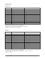
1
micromodul LD2
User manual
Content
Provision of guarantee and product liability .............................................................................. 2
Safety precautions and servicing................................................................................................ 2
Introduction ................................................................................................................................ 3
Product description..................................................................................................................... 4
System requirements .................................................................................................................. 5
Quick Access.............................................................................................................................. 5
Tips............................................................................................................................................. 6
Power Supply ............................................................................................................................. 7
Connecting to a computer .......................................................................................................... 8
Which software can be controlled.............................................................................................. 8
Settings in the system mode ....................................................................................................... 9
Preparations in Live ................................................................................................................. 10
Working with Live ................................................................................................................... 11
Working with other programs .................................................................................................. 12
Value-indications on the LED-bar ........................................................................................... 14
Parameter-Feedback ................................................................................................................. 14
Expanded sets........................................................................................................................... 17
Controller numbers................................................................................................................... 18
micromodul LD2
Page 1
User manual
Provision of guarantee and product liability
The seller warrants for faultless material and proper manufacture for a period of 24 months
from the date of sale to the end user.
Excluded from the stated guarantee are defects on parts as the result of normal wear-and-tear.
These parts are mostly faders (sliding guides), potentiometers, encoders, buttons, switches,
and joysticks.
Also excluded from the guarantee are damages that are the result of :
incorrect or inappropriate handling, excessive force, mechanical or chemical influences,
incorrectly connecting the instrument with other instruments, incorrect or inappropriate use.
The warranty is void if the instrument is opened or changed. In addition, there is no warranty
for individual parts and components (in particular, semiconductors) and disposables/
consumables. The seller is not liable for consequential damages which are not the result of
criminal intent or negligence on his part. The following conditions must be met in order to
claim the warranty services:
- Instrument is either in its original packaging or similar packaging.
- Copy of the invoice with the serial number clearly visible.
- Meaningful error report or description of the error is attached.
The buyer assumes all costs and dangers of return shipments to the manufacturer. Since the
user’s manual which is included with each instrument also affects the warranty conditions
(especially regarding safety issues), it is absolutely essential that you read through and follow
all instructions.
Safety precautions and servicing
- Instrument'
s intended use is based on the functions and procedures contained in this manual
- Read all instructions for use as well as all enclosed literature before using the instrument
- Use only in closed rooms (not for outdoor use)
- Never use in a moist or humid environment (laundry rooms, swimming pools, etc, …)
- Not for use in the vicinity of heat sources (radiators, ovens, etc, …)
- Operational temperature is in the range of 0° - + 40° C
- Not for use in the vicinity of flammable material
- The instrument should not be in direct or prolonged contact with sunlight
- Dusty environmental conditions should be avoided
- Only for use with mains adaptors which comply with the specifications in this manual
- Only for use batteries which comply with the specifications in this manual
- Pay attention that batteries do not leak while in the instrument (esp. during extended storage)
- When connecting to other instruments, pay attention to the instructions in this manual
- No foreign objects are permitted inside the instrument casing
- No liquids should get inside the instrument casing
- Never let the instrument fall to the ground (casing and/or control elements may be damaged)
If the instrument must be opened (for example, to remove foreign objects from the casing or
for other repairs), this may only be done by qualified personnel. The batteries must be
removed and the mains cable must be disconnected before opening the instrument. Guarantee
is void for defects that occur if the instrument was opened by an unauthorised or unqualified
person.
Use a soft towel or brush to clean the instrument. Please do not use any cleaning liquids or
water, so you avoid any damages to the instrument.
micromodul LD2
Page 2
User manual
Introduction
It is 2007. After the successful start of the micromodul 2 series it is finally time to get some
important enhancements in the form of new controllers off the ground.
Musical arrangements are the largest creative aspect in many areas of modern music. Also,
the creation of new sounds and loops using the processing power of computers allows a large
amount of fun from the very start. We all know that really promotes creativity. You only need
three tools in order to use the new possibilities in loop-based ”computer music” :
- A computer (a laptop would be best)
- Intuitive software such as Live from Ableton
- A hardware controller like the micromodul, optimised for the software
We designed a controller to support the playful use of loops. Without a doubt, Live from
Ableton is a tool which, in itself, offers a huge potential when working with this sort of
music. But, let’s face it, who wants to drive a car with a computer keyboard or a mouse? Fact
is, slide controls, knobs, joysticks, buttons, and LED’s are as much a part of electronic music
as steering wheel is to a car.
Micromodul LD2, also called just LD2, is a pocket-size, custom-made controller for one of
the most creative music programs in recent history. The LD2 is very compact and easy to
transport, and you do not even need the mains adaptor, it works with standard and
rechargeable batteries.
This controller is an essential addition to our LV2/LC2 controllers.
16 push-encoder (endless-potentiometer with integrated key) are united in a very compact and
low-priced controller, which is perfect for jump-free controlling.
You can switch the encoders to 6 different control-sets, which offers you all of the encoderfunctions (send, EQ, clip, FX) of the LV2/LC2 controller when working with Live, and 2
control-sets (2 x 16 parameter) at your free disposal. Two control-sets enable simultaneous
control of the send- or EQ-parameter for 4 tracks. Another control-set may be used to
completly control one track (send, EQ, clip, volume, pan, mute, solo) as well as scrolling
through clips/scenes and starting them.
The selected track/s are indicated on a LED-bar and can be switched with 2 keys.
Even the values of each encoder can be indicated on this 13-unit LED-bar.
Because a file with the right settings comes with the controller, you can start directly with
Live from Version 4.1 without any lenghty learning of controller-numbers.
You can also use the LD2 with other programs. Due to it’s special architecture, the controller
is suited very well for any kind of music-software. Encoders and keys can be programmed in
9 internal free programmable setups, whereas 6 control-sets with 16 encoders are for free
disposal for each setup.
Read this user’s manual thoroughly. Even if the design of the LV2-controller is largely
intuitive and the instrument is self-explanatory, this manual should be able to answer a
question or two. If you should have any sort of other problem with your micromodul, just
contact us via email.
micromodul LD2
Page 3
User manual
Product description
-
-
-
-
-
-
-
Special-controller for jump-free control by CC/Note-Midi-commands (optimized for
Ableton Live)
Easy plug & play through provided setup-files for Ableton Live from Version 4.1
Independent of system software and computer-model (PC or Mac) due to the midi
interface
16 push-encoders switchable to 6 control-sets
Programmable rotarymode (absolute/relative), CC/Note-numbers (in groups of 16
ascending numbers), acceleration-function
Different push-button-modes CC-toggle, note-commands like from keyboards,
acceleration-function by holding the encoder
Trackselect with 2 keys and 13-unit LED-bar for Live-Mode 1-track-control & 4track-control (also controllable with connected LV2/LC2/LX2)
12 setup-memories (9 are free programmable)
Feedback of key-status and parameter-values of Live is indicated by 16 encoderLED’s and a 13-unit LED-bar
Independent power supply by standard or rechargeable batteries 3 x AA
cell, lifetime about 30 to 60 hours
-
Powersave mode after 10 minutes of the last movement (running light)
-
LED battery control
-
Socket for an external power adaptor (4.5-6V DC - min. 50 mA)
-
Midi-merge function
-
-
-
-
Very compact design in a black, plastic casing
(desktop format 180x105x70mm, 450 g)
Silver aluminium front plate with anodised coating (abrasion resistant) and
inscriptions
36 LED's in different colors to display various information (low light shining of all
LED’s for better orientation in dark club atmosphere)
High-quality encoders from ALPS
Expandable system by other micromodul controllers
(easy chaining by midi connections)
micromodul LD2
Page 4
User manual
-
Compatible to the 1st/2nd micromodul line (same cc/note numbers like LV1, LX1,
LV2, LC2, LX2)
System requirements
-
PC or Mac with a Midi-Interface (Midi-input, Midi-output is necessary if you want to
use the functionality of parameter-feedback)
-
Ableton Live or software which allows self-assignments of midi-controls for
continuous parameters or key commands for switching parameters.
(Optimal with Ableton Live as of version 4.1 with the enclosed setup file)
Quick Access
After you have done all of the relevant midi-connections and settings in Live (see further
down) and loaded one of our setups (preferably ‘micromodul LV2 V01 A6M6 Live50.als’),
the fun may begin...
Setup 2 must be set in system mode (factory setting) in order to take the first steps and the ‘1track-control’ control-set must be active (left black key).
Just use your mouse to drag and drop a few clips from the browser to any slots in the different
first 6 audio tracks. It is best to choose several sequent clips (hold shift or ctrl-key and click
the files) from the start so you have a choice of clips in each track. You can start these as
usual with your mouse, but it is more comfortable with the slot/scene-encoder (at the far
upper right). Scroll vertically (across the slots) with the encoder. By pressing it you can start
the chosen clip. The LED above the encoder always indicates you whether there is a clip
playing in that slot (indication only possible from version 6.0). By pressing the encoder
below, you can stop the selected track. The selection of tracks happens with these two grey
track-keys. This way you can move easily through the “matrix” and quickly launch a clip.
Now adjust the volume of the selected track by using the volume-encoder right below or just
mute the track by pressing this encoder. The pan-encoder above can move the track in the
panorama and by pressing the encoder it is set to solo. With the corresponding LED’s you can
see, which track is currently active (not mute) or set to solo.
The master-track can be controlled just as any other track. First change the track-display to
‘M’ (pressing shift and the right grey key is usually the fastest way).
If one of the clips still misses some stridence, it may need a little bit of EQ. This is easy...
You can control the gains of the 4 EQ-filter in your selected track with the encoder of the
second column from left. In order to bring the gains quickly down to zero, you just need to
press the encoder. The LED’s above the encoder indicate, whether the corresponding filter is
active or not.
But even the control of clip-parameters is easy with the LD2 (from Live Version 5.0). To do
so, you choose the desired clip and use the encoder of the third column from your left. With
the first encoder (transpose) you can transpose the track, whilst you can choose the length of
a loop with the lowest encoder (loop-stop). (Be cautious, the global quantization of the
micromodul LD2
Page 5
User manual
quantization-menu just above at the display border has to be on 1/8 or 1/16). Just a quick
stutter-effect, extremly distuning the clip or playing the clip a bit tonal is no problem. It is
very easy to handle due to the encoder snatches.
As generally known Live is full with a number of crazy effects, which you can control
brilliantly with the LD2. So quickly drop a Grain-Delay-Effect from the browser into a track
and switch with the black key to FX-A control-set.
We deliberately did not take the FX-assignments into our setups to leave the choice up to you.
So you have to set your hand to it and you will see how easy it is to assign the controlelements on your own. Please consider that all parameter of the FXA, FXB and FXC controlsets send relative data. This has to be identified as such by Live in order to guarantee a correct
control. For every single allocation there should appear the channel/controller number and the
control mode ‘relative 2’s comp’ in the bottom segment of your monitor. This will be
achieved by slowly turning the encoder a few steps to the left.
After you activated the midi-mode in Live (small midi-key at the upper display border), you
click the small digit display left to frequency in the grain-delay-window and move the first
encoder (no.1) a few steps to the left (number 15/24 appears in the window).
To switch the effect on or off, we allocate the push-button of the same encoder to it. To do so,
click the small display just left in the headline of the grain-delay-window and press the
encoder (number 15/C7 appears in the window). The corresponding LED will indicate the
status of the effect from now on (LED shines = effect on).
Now click on the digit display in the grain-delay-window left to pitch and turn encoder no.2.
The corresponding controller-number (15/25) appears in the window. After that click on the
small digit window next to feedback and turn encoder no. 3, the allocated controller-number
(15/26) appears in the window.
Now you can control the effect and you can exit the midi-mode in Live again.
Just try all of the assignments. If you want to change the clip of your track, push the black 1track-control-key and change and start the clip with the encoder right above.
Tips
Please always take substitute batteries or rechargeables with you. When the yellow LED starts
blinking, it is time to change the batteries quickly (about one more hour left).
Arriving mididata is signalled as a flickering light from the Sys-Mon-LED in the system
mode. This is a way to check the correct cable or settings in Live.
If you want to use the LD2 completely for your own allocations, you should use setup 4 - 12.
These setups guarantee a simple start without programming, but they are still adaptable to
your own alternations after all. Setup 4-11 are originally adjusted in the way, that encoders
and their corresponding keys send different cc-commands. Thereby the keys can control
independent functions. For factory setting setup 12 the keys send the same cc-commands as
the corresponding encoders, so you have an additional possibility to switch the parameter to
min- or max-value by pressing the key.
Program the encoders and the corresponding keys to the same CC-numbers in setup 4 – 12.
Thereby the encoder-value will be indicated by the encoder-LED (value zero = LED off,
value bigger than zero = LED shines). Also see factory settings setup 12.
micromodul LD2
Page 6
User manual
To select the master-tracks press the shift-key and the right grey key. This way you can easily
choose and start a new scene (via the slot/scene-encoder in the 1-track-control control-set).
By holding the shift-key and pushing the encoder the value of the encoder is indicated by the
LED-bar. (for exceptions see chapter ‘Value-indications on the LED-bar’) This mode is
indicated by the green value-LED below the bar. By pressing the shift-key once again you
can switch off the mode.
Do not necessarily try to use all of the allocations and switch possibilities for your
performance, because you can easily start a function you did not mean. Especially switching
between the different control-sets mislead to bring out everything of the LD2, which is a nice
thing to do at home or in the studio, but not for a performance.
If you put your LD2 behind the LV2/LC2/LX2 in a midi-chain, you can easily control
trackselect for the LD2 with the other controller.
A complete update of all LD2-display and –encoder can be achieved by shortly activating the
midi-function in Live (small midi-switch right above in the Live-window). This functions is
very handy, after you have changed a setup or switched off the LD2 for example.
Power Supply
The LD2 does not contain an internal mains unit. It was primarily designed for use with
standard or rechargeable batteries (3 x AA cell 1.2-1.5 V alkaline, NiCd, NiMH) which are
inserted into a compartment on the bottom of the instrument. Please pay attention to the
battery poles when changing batteries. This compartment has a safety screw which must be
removed before batteries can be exchanged. Batteries usually last between 30 and 60 hours
based on quality and brand. In order to increase the battery life-span, the instrument switches
into its energy-saving-mode 10 minutes after the last movement was made on any controller.
An LED running light displays the energy-save-mode. The instrument is still fully functional,
only the LED’s are switched off to save power. The instrument leaves the energy-savingmode as soon as a control is moved (primarily Shift). The battery control LED (yellow SysMon LED) blinks when the batteries need to be replaced.
By holding shift (at least 5 seconds) without any other fader or key the powersave-mode will
be activated.
The LD2 can also be used with an external mains adaptor. The adaptor (regulated or not)
must have a DC voltage of 4.5-6 V and at least 50 mA.
You can find a suitable mains adaptor in our accessories.
The adaptor plug (hollow plug: 2.1 mm inner / 5.5 mm outer) must be polarised according to
the information on the connection plate: outer ring = minus, inner pin = plus.
For wrong polarity of the plug the controller will not work. A damage is however impossible.
You switch on the LD2 with the power-switch at the back (LED’s shine). If the power-switch
is on Adaptor, the power will be supplied by the external mains adapter. If the switch is on
battery, the battery will provide the electricity.
Pay attention to always switch off the controller in the battery-mode if not used, because that
increases the durability of the batteries.
micromodul LD2
Page 7
User manual
Connecting to a computer
A midi cable is used to connect the LD2 to a computer – and to the software. This cable is
connected to the midi-out slot on the controller and the midi-in slot on the computer (sound
card or midi interface). In order to use the new possibilities concerning the parameterfeedback of the second line, you should also connect the midi-in-port on the LD2 with a midiout slot on the computer. The midi-in slot on the LD2 is also used to connect additional
controllers and keyboards to the same midi-port on the computer. The data is then merged in
the LD2.
Of course, many users will now wonder why this controller does not have an USB interface.
The micromodul system is a system of multiple controllers that is able to be cascaded via
midi. This is not as easy with USB, especially because the units can control each other due to
the cascading. In addition, many computers with sound cards or USB/Firewire audio
interfaces have a midi interface. This means you would not have to use one or more of your
USB ports to use the whole micromodul system.
If your computer does not have a midi interface, or your sound card does not have one either,
the market offers a number of small and inexpensive solutions in the form of an USB midi
interface that has both a midi-in and a midi-out slot. In combination with the micromodulsystem this is absolutely sufficient. Following recommendable hardware are hardly bigger
than a cable:
M-Audio MidiSport Uno, Edirol UM-1EX, ESI RoMI/O.
Which software can be controlled
The LD2 was designed primarily for the usage with Live from Ableton as of version 4.1. You
can find a file with the matching controller-settings on the disc enclosed. Live versions before
4.1 can not be completely controlled (no clip selections and control, missing feedback etc.),
but they can still be allocated with the LD2.
Of course you can also control other sequencer-programs or software-instruments. The large
selection of parameters makes this controller an interesting solution for any kind of music
software. 9 free allocatable setups (setup 4 – 12) can send each 6 x 16 different controlchange-parameter through the encoders. Additionally there are another 6 x 16 parameter
independent of control-change- or note-on/off-commands due to the the encoder-keys.
The 16 encoder can be changed between 6 control-sets.
For free setups the track-keys send another control-change-signal for all 13 steps (1 to 12 +
M), which is very appropriate for switching functions.
If you would like to use this controller for other programs, you should first make sure it is
possible to control the software-parameter via fixed midi control numbers, since the LD2 is
only limited programmable concerning these numbers. The programming takes place in steps
of 16 numbers, where all encoder in a control-sets have rising numbers. For switching
functions you can allocate additionally fixed midi-note-numbers. The LD2 sends fixed
control-change- or note-on-events (when being pressed) and note-off messages (on release)
for all encoder.
LD2 is not full programmable and you can only set controller numbers or key numbers
limited, but that is a function that is rarely needed with current programs.
micromodul LD2
Page 8
User manual
The corresponding assignments are noted in the last chapter, ”Control numbers”.
You will find out how many parameters you can control and how you can switch modes in the
following chapters.
Settings in the system mode
You can activate the controller’s system mode if you press both of the control-set-keys 1C &
2A. The yellow Sys-Mon-LED next to shift is on to signal this mode.
No midi signals are sent as long as the controller is in this mode. Only the incoming
commands via midi-in slot are sent directly to the midi-out slot (as long as the feedback-killer
is not activated).
The assignments of the LED’s in the system mode are indicated on the backside of the
controller.
In order to exit the system mode and to restart the controller in the normal operational mode,
just press these two buttons again. After that all LED’s will turn off for two seconds and the
system is restarted.
During this restart procedure, all changes made in the system mode are stored. If you turn the
instrument off while it is in the system mode, all changes will be lost.
In the system-mode following settings are possible:
Feedback-killer
The Feedback-killer is an essential function in connection with the ability of the LD2 to
absorb feedback from Live. Since the controller is connected bidirectional with the midi-in
and out slot of the computer and consequently with Live, the data sent from Live will be sent
through the controller and back to Live (midi-merge-function).
In doing so a back coupling effect (feedback) originates, which brings Live occasionally into
the condition of ‘moving’ parameters. Beyond that several key combinations are not possible
anymore. To avoid this but at the same time enable the usage of several controller,
the feedback-killer was implemented.
When and for what controllers in a chain this functions has to be activated is explained in
more detail further down in chapter ‘Parameter-feedback/arrangement’.
The activate this function in the system-mode you have to press the left control-set-key:
- LED 1A on = feedback-killer deactivated
- LED 1B on = feedback-killer activated
Setup
12 different setups can be chosen in the system mode by using the track-keys:
LED 1 = Setup 1 for Live (CC/Note-data send on channel 10-12)
LED 2 = Setup 2 for Live (CC/Note-data send on channel 13-15)
LED 3 = Setup 3 (sends seperate CC-data for encoder and keys on channel 2 & 3)
LED 4 – 12 = Setup 4-12 (programmable setups, optional for channel 1-12)
If you want to use the provided Live-Setup-data, you need to choose setup 2. Setup 1 – 3 are
not changeable.
micromodul LD2
Page 9
User manual
Preparations in Live
First of all you have to copy our ALS-files from the CD (in the micromodul/LV2 directory) to
your computer. We have prepared different Live-Sets:
micromodul LV2 V01 A6M6 Live41.als with 6 audio-tracks and 6 midi-tracks
micromodul LV2 V01 A12 Live41.als with 12 audio-tracks
micromodul LV2 V01 A8S4 Live41.als with 8 audio-tracks and 4 sends
micromodul LV2 V01 A6M2S4 Live41.als with 6 audio-tracks, 2 midi-tracks and 4 sends
micromodul LV2-DJ2 V02 A6 Live41.als with 6 audio-tracks and send-control via DJ2
micromodul LV2 V01 A6M6 Live50.als with 6 audio-tracks and 6 midi-tracks
micromodul LV2 V01 A12 Live50.als with 12 audio-tracks
micromodul LV2 V01 A8S4 Live50.als with 8 audio-tracks and 4 sends
micromodul LV2 V01 A6M2S4 Live50.als with 6 audio-tracks, 2 midi-tracks and 4 sends
micromodul LV2-DJ2 V02 A6 Live50.als with 6 audio-tracks and send-control via DJ2
In these sets we prepared a lot of control and button assignments for you, which will surely
guarantee a comfortable start. Following elements are already assigned:
- Encoder (Send, EQ, Volume, Pan, Clip-select, Clip-control) !!! Clip-control only
works for Live50-Sets
- Encoder-Keys (Send/EQ-Reset, Mute, Solo, Launch, Stop)
- Track-Keys (Track-select)
There are further assignments for the sets in connection with the DJ2, which are described
further in the DJ2-manual.
Live41-sets work for all Live-versions up from 4.1 so also in 5.0 or higher.
Live50-Sets, which work up from Version 5.0, differ in so far, as clip-control is possible.
For Live-Versions before 4.1 we don’t have any configurations, since these versions can not
be controlled fully. But you can also create some sets on you own for earlier versions (see
next chapter).
After the midi connection between the LD2 and the computer has been established, start Live.
Next, select the midi port to which the LD2 is connected to. You have to switch the
appropriate In- and Out-Ports to remote control. You can find them in the Live-preferences
under Midi/sync. Open one of the Live sets listed above. All of the important control
assignments to the individual control elements are then established. Play around a bit with the
controls and knobs on the controller and check if you see the corresponding reaction on your
monitor. If nothing happens search for possible reasons in chapter ‘trouble-shooting’.
Controlling your Live-Sets
There is, of course, also the possibility of making adjustments between the software and the
controller via the learn function of Live. You will need this function in order to control
additional functions or make changes.
If you would like to control your existing Live-set using the LD2, you either need to input all
adjustments with the learn function in Live or copy all clips in one of our sets.
We reckon that in the foreseeable future Ableton will bring out a special driver for
micromodul. With this all assignments (according to our sets) will be available without
loading a special set.
micromodul LD2
Page 10
User manual
Assigning the controller in Live
First, activate the learn mode in Live by pressing the midi switch on the upper right of your
monitor. The actual learning process consists of selecting the control element or slot/scenes
and then moving the desired fader or activating the desired keys or keycombinations (with the
Shift-key). If your assignment was successful Live displays the midi channel and controller
or note number plus the control mode (Absolute or Relative (2’s Comp.)) in the bottom
segment of your monitor.
Recommendations for the assignment:
- allocate all elements from one track before switching to another track
- turn the encoder for control-sets FXA, FXB, FXC several steps to the left
(counterclockwise) and check, whether Live recognises the controller as ‘relative (2’s
Comp.)’ !!! The encoder in control-sets 1-track-control, 4-track-send and 4-trackEQ send absolute-data !!!
The next chapter will explain how the various functions of the encoders and keys can be
accessed. As soon as everything has been assigned, exit the learn mode by pressing the midi
switch in the program.
Working with Live
The 16 encoders can be switched to different targets with 6 selectable control-sets. You can
change between control-sets with the 6 black keys at the lower border. The activated controlset is indicated by the red LED above the keys. The control-sets are optimized for working
with Live, they represent the LV2/LC2-encoder-functions. It is very comfortable to extend
your midi-controller with a LD2; since the allocated parameter in the LV2/LC2 are
immediately accessible for the LD2.
Track-select
The two grey keys on the left top are for the necessary selection of tracks for the first 3
control-sets 1-track-control, as well as 4-track-send and 4-track-EQ. Which of the 13
possible tracks is selected currently, is indicated by the red LED-bar at the upper border. ‘M’
stands for mastertrack. The selected track-quaternary is indicated for the 4-track- control-sets.
Of course you can also control the selection of tracks with other controllers (LD2, LC2, LV2,
LX2) as long as there are chained prior to the LD2.
Please consider, that you always control the track or track group indicated by the LED-bar of
the LD2, even if another track is selected in Live.
control-sets
With the first and most extensive control-set 1-track-control you can control the most
important functions of a track. 4 send- and 4 EQ-encoders as well as volume or pan control
the according parameters. To reset the according parameter use the keys of the send- and EQencoders. The LED above shines if the parameter value is not zero, which means that the
according function is active:
- send-LED shines = signal goes to send-bus
- EQ-LED shines = EQ is active
The keys of the volume or pan-encoder can be used to mute the track or switch it to solo,
which again is indicated by the corresponding LED:
- mute-LED shines = track is active (LED is Live-controlled)
- solo-LED shines = track is on solo-switch (LED is LD2-controlled)
micromodul LD2
Page 11
User manual
Encoder No. 8 is still disposable and can be allocated to a track-related parameter.
Slot/Scene-encoder No. 4 right above has a special function, which is the same for every
track. He can be used to scroll vertically through the slots/scenes. The selected clip/scene will
start in the current track if you press this encoder. The LED is controlled by Live and
indicates, whether a clip is playing in the corresponding track. The running clip/scene can be
stopped by pressing encoder No. 8 just below the start-encoder.
Furthermore you can control the clip-parameter transpose, gain, loop-start and loop-stop
with this control-set. You always control the selected clip in Live, independent of which track
is selected in the LD2. The LED of these 4 encoders have no functions and the keys are
allocated as follows:
- transpose = not allocated
- gain = set start-mark to the current position
- loop-start = set loop-start to the current position
- loop-stop = set loop-end to the current position
The send-encoder and the mute/solo-keys are without any function if the mastertrack is
selected, but you can allocate them yourself. The start- and stop-functions of encoder 4 & 8
are then used to control the corresponding scenes.
Control-sets 4-track-send & 4-track-EQ should be used for controlling the corresponding
parameter of 4 tracks simultaneously. The 4 tracks, which are chosen through the track-select
described above, are controlled column by column. The LED and keys have the same function
as described above for control-set 1-track-control.
The last 3 control-sets FXA, FXB and FXC are free for disposal, since they are not allocated
in the provided setups. All encoders of these control-sets send relative data and the
corresponding keys can be allocated independently of the encoder-function. You just need to
consider the note-commands sent by the keys of the encoders 1-12 of control-set FXA:
- press key = note-on-command
- release key = note-off-command
Encoder-keys 13-16 as well as every encoder-key of the control-sets FXB & FXC send cccommands in the toggle-mode:
- press key = cc-command with value 127 (maximum/on)
- press key once again = cc-commands with value 0 (minimum/off)
The status, which is indicated by the LED, can be generated by the LD2 itself or can be
controlled by Live. So the indication is possible without parameter-feedback.
Edit mode
The settings in the edit mode of Live-setups 1 & 2 are narrowed down to the choice of the
acceleration-function (acc). More information are described further down in the chapter ‘edit
mode for setup 4-12’.
Working with other programs
The LD2-controller is not only a specialist for Live. Since it is programmable to a large
extent, you can adjust it to many other programs. The controller can send control-changecommands for 3 different modes as absolute and relative data. The encoder-keys can send cccommands as well as note-commands. The numbers of the controller or notes are separately
adjustable as semiquaver for each of the 6 control-sets. The 16 encoders of a control-set are
then allocated with 16 rising numbers.
micromodul LD2
Page 12
User manual
Another switch between min- and max-values is possible through programming the keys to
the same cc-numbers as the encoders. !!! This works only properly if the encoder does not
send in a relative-mode !!!
Since the LED are linked to the keys of the encoders, they always indicate the status of the
corresponding controller:
- LED shines = value bigger than zero
- LED off = value equal to zero
The track-keys have a special functions for setup 3-12. By pressing the key another cc-value
with value 127 is sent for each of the indicated positions on the LED-bar. You could use this
function for any sequential switching for example.
Edit mode for setup 4-12
The programming of the single control-sets is made in the edit mode. If you want to create
your own control-sets, you have to choose one of the setups 4 to 12 in the system mode (setup
1 – 3 are only limited or not editable).
You enter the edit mode by holding the shift-key down and press one of the 6 black controlset-keys at the same time. A flashing red LED signals you, which control-set is ready for
editing. The choice of control-sets is also possible in the edit mode. The actual programming
is done with the track-keys and the keys of the 16 encoder. The available parameter are
printed in the right lower corner of each encoder-area on the control panel. The functions of
the encoder and their keys are programmed together for one control-set generally.
The 2 grey track-keys set the midi-channel of the control-set. The red LED-bar indicates the
chosen channel from 1-12. The ctrl-sets 1A – 1C as well as 2A – 2C have a common midichannel each.
Encoders 1 – 8 determine the encoder-function and the lower encoders 9 – 16 program the
encoder-keys.
First you can choose a cc- or note-number area for both sections (encoder & keys). The
numbers 00, 16, 32, 48, 64, 80 printed on the control panel show the start number for the
control-set. As an example, if you press encoder No. 2 with start number 16 and encoder No.
14 with start number 80, the encoder of the control-set will send following controllernumbers:
- encoder 1 = cc 16, corresponding key = cc/note 80
- encoder 2 = cc 17, corresponding key = cc/note 81
- encoder 3 = cc 18, corresponding key = cc/note 82
- .......
- encoder 16 = cc 31, corresponding key = cc/note 95
Encoder 7 (Rel1) & 8 (Rel2) can set the control-set to one of two possible relative-modes. By
doing so all encoder only send information of the kind ‘increase value’ or ‘decrease value’.
This can be very convenient in the sense, that definitely no value-jumps occur (even without
parameter-feedback) and the value-area can be controlled with a finer resolution independant
of the software (as an example, Live has a resolution of 256 values instead of the normal
128). The two relative-modes only differ for the used codes. You should simply try, which
one works for your software. If none of the two modes is chosen, the LD2 sends absolute data
in a value-area from 0-127, which can be processed by any software.
You can also choose 3 different modes for the keys of the encoders. Through encoder 15
(note) you can switch the keys of a control-set to note-mode, so you can use them as a normal
midi-keyboard. When pressing a key a note-on-signal will be sent and when letting go a notemicromodul LD2
Page 13
User manual
off-signal will be sent. You can set the note numbers for the encoder-keys of the control-set
with encoder 9-14 (see above).
With mode ‘Acc’ (encoder 16) the encoder-keys get a real special function. By pressing the
encoders and turning it at the same time, the encoder will be ‘accelerated’, which means they
send larger value-steps. That way they can drive through the whole value-area with a few
turns. When turning the encoder without pressing it, the fine resolution without any
acceleration functions is used. If the ‘Acc’-function is activated, the encoders work with a fine
resolution and an automatic acceleration by fast turning, which will be the more comfortable
way for most situations.
If none of the two modes (Note or Acc) is chosen, the keys send normal cc-commands in the
toggle-mode. For every pressing you change between value 0 and 127, depending on the
existing status, which is indicated by the LED. The cc-numbers are set again with encoder 914 (see above).
The storage of the programming in the edit mode happens either when changing the controlsets or when exiting the edit-mode. To do that you have to press the shift-key and a controlset-key at the same time.
Value-indications on the LED-bar
The advantage of an encoder is that you can control values without any jumps. But you also
have to see the disadvantage of not being able to identify the current value on the controller.
This feature is achieved with the so called LED-rings/bars, which then indicates the value.
With help of the LED-bar at the upper top such an indication can be realized on the LD2. This
way you have the obvious advantage, that you do not have to look at the screen in order to
check the encoder-settings either for controlling it or when turning it.
Just hold down the shift-key when pressing down the encoder key and the corresponding
value will be indicated by the LED-bar. This indication always changes to the last turned
encoder. By simply pressing the shift-key it will turn back to the indication of tracks. The
green value-LED below the bar shines if the value-indication is active.
You should be aware, if your encoder works in a relative-mode the value-indication for your
encoder-values may only work, if that parameter-feedback between the program and the LD2
works correctly. This is the case for the control-sets FXA, FXB, FXC in the Live-Setups.
There the indication will be delayed for your encoder-movement. The clip-parameter
(transpose, gain, loop-start, loop-stop) as well as the slot/scene-encoder in the Live-setups
can not be indicated by the LED-bar.
The shift-function in order to activate the value-indication is not available on encoder 2, 3 and
4 (upper row) of the control-set 1-track-control in the Live-setups, since these are reserved
for future features. The values of these encoder are indicated when turning them anyway and
the value-indication is active.
Parameter-Feedback
The LD2 does not just send Midi-Signals but also analyzes and shows signals that arrive. This
way it is possible to include the parameter-feedback from Live in the control.
Status-messages of switching functions are indicated by the LED and even the current
encoder-positions get to the LD2. With help of the value-indication described further above
micromodul LD2
Page 14
User manual
those messages are used for indication and the encoders use these information partly in order
not to create any value-jumps when turning them.
Especially the new indication-possibility in the form of the 16 encoder-LED profit from this.
All status-feedback is indicated here, so that an exact copy of the Live-surface is possible on
the LD2. The indication of the solo-functions are generated from the LD2 itself. They are not
necessarily identical to the Live-surface, but they always indicate the last track set to solo on
the LD2. The are programmed in the way, that only one track is on solo-function. So please
be aware, that the exclusive-functions ‘solo’ is activated for the Live-presettings/diverse. The
indication of the current scene is not possible right now (version 6).
A total update of all LD2-indication can be achieved by temporary activating the midifunction in Live (small midi-switch right above the Live-window). This is necessary, if the
LD2 was switched off or turned to the system mode.
Generally it is not necessary to use the parameter feedback. The control is possible without
the feedback as well, but this is not as comfortable.
Arrangement
When arranging a micromodul-system you have to be aware of only a few but very important
things in order to use the parameter-feedback feature.
First of all you have to establish a midi-chain, that means the midi-out slot of the computer is
connected to the midi-in slot of the first micromodul-controller (usually the right controller),
further from the midi-out slot of that instrument to the midi-in slot of the controller to its left
and so on. The last micromodul in this chain (the instrument on the left) has to be connected
from it’s midi-out slot to the midi-in slot of the computer. The corresponding in- and out-ports
in Live have to activated as well (switch on the remote control in preferences/midi).
Beyond that following things have to be considered:
- only activate the feedbackkiller-function in the first (right) controller, whose midi-in is
connected to the computer
- in a system of several different micromodul-controller an instrument with feedback
killer-function (for example LV2,LX2,LC2,LD2) has to be used as the first (right)
instrument (you can’t use a DJ2 or DX2 since they don’t have this function).
If these two rules are disregarded, either not every controller is available for controlling or a
midi-feedback happens. This means that the fader begin to flicker or the switching functions
are incorrect. If the parameter-feedback is not used and another external midi-instrument (for
example a keyboard) is connected to the first (right) micromodul instead, the feedback killerfunction has to be switched off in every controller, otherwise no passing through of the mididata from the external instrument takes place.
The following drafts show 2 possible configurations:
micromodul LD2
Page 15
User manual
micromodul LD2
Page 16
User manual
Expanded sets
micromodul is a system of controllers: single controllers which are easily combinable and
expandable to create a complete system. Just connect the instruments with their midi
interfaces, and the system is ready for use.
The instruments are normally connected from right to left. That means the midi-out slot for
the instrument to the right should go into the midi-in slot of the instrument on the left and so
on. (also see draft above)
An important point when combining the LD2 and LV2/LC2/LX2 is the order in which they
are connected. If you want to control these instruments in a useful manner, the LD2 should be
after the LV2/LC2/LX2 in the midi chain – so, connect the midi-out on the LV2/LC2/LX2 to
the midi-in on the LD2.
Controllers that accept commands must always be after controllers which send commands
through the midi chain.
In order to analyse parameter-feedback from Live, the midi-in slot of the first (right)
controller has to be connected to the midi-out slot of the computer. Please also read the
settings concerings the feedback in the chapter above.
Working with micromodul LV2 or LC2
Even though the LD2 itself enables a good control, it is thought as an addition to the
LV2/LC2/LX2.
Especially for the sequencer Live several micromodul-controller together bring you a lot of
advantages. Micromodul is conceived in the way, that the controller can supplement each
other. With two LV2/LC2 + LD2 you can comfortably control the tracks and, without having
to switch, you can control the parameter EQ, send and so on for every track at the same time.
Track-select is transferred between the controller, so that both controller can be on the same
track after a change of tracks with the right controller. All encoder-functions of the LV2/LC2
are represented in the LD2, which means, everything fits immediately and can be controlled
parallel on the controller.
Additional keys with the micromodul LX2
Our LX2 was designed as an addition. A controller with 36 control buttons – all of which
have the same colour scheme as the LV2/LC2. You can use this instrument to carry out all of
the switching functions of the LV2/LC2, but you will not have to switch the tracks first
anymore. All track control functions are accessible directly for 6 tracks, but you can have one
function (for example Mute or Launch) accessible for all 12 tracks. Another strength of the
LX2 is the possibility to start 36 slots/scenes (even up to 108 are possible by using the keysetswitch). Track control functions, slot start functions, track-select and even more can also be
mixed among the keys/buttons – configure it according to your personal needs. There is an
endless number of combinations possible. An 1-octav-mini-keyboard with octav-shift-keys
makes it possible to quickly trigger a midi-instrument in Live without being forced to use the
master keyboard.
Finally the optimum setup looks as follows: LD2 + LV2 + LC2 + LX2. 12 tracks with all
corresponding switching functions at direct control + all kinds of rotary-controls. There is
hardly anything better than that....
micromodul LD2
Page 17
User manual
Controller numbers
Control-set 1-Track-Control (setup 1 / 2)
Encoder-No
1(Send A)
[abs]
2(EQ High)
[abs]
3(transpose)
[rel]
4(slot/scene)
[rel]
5(Send B)
[abs]
6(EQ Mid 2)
[abs]
7(gain)
[rel]
8
[abs]
9(Send C)
[abs]
10(EQ Mid 1)
[abs]
11(loop start)
[rel]
12(pan)
[abs]
13(Send D)
[abs]
14(EQ Low)
[abs]
15(loop stop)
[rel]
16(volume)
[abs]
Control-Change-Number Encoder Control-Change-Number Encoder Key
Note-Number Encoder Key
40-51 (Ch=10/13)
40-51 (Ch=10/13)
56[Master track] (Ch=10/13)
56[Master track] (Ch=10/13)
100-111 (Ch=11/14)
100-111 (Ch=11/14)
116[Master track] (Ch=11/14)
116[Master track] (Ch=11/14)
20 (Ch=12/15)
104 (Ch=12/15)
41 (Ch=12/15)
60-71 (Ch=10/13)
76[Master track] (Ch=10/13)
80-91 (Ch=11/14)
96[Master track] (Ch=11/14)
21 (Ch=12/15)
0,8,16,24,32,40,48,56,64,72,80,88 (Ch=10/13)
0[Master track] (Ch=12/15)
60-71 (Ch=10/13)
76[Master track] (Ch=10/13)
80-91 (Ch=11/14)
96[Master track] (Ch=11/14)
105 (Ch=12/15)
0-11 (Ch=10/13)
16[Master track] (Ch=10/13)
80-91 (Ch=10/13)
96[Master track] (Ch=10/13)
60-71 (Ch=11/14)
76[Master track] (Ch=11/14)
22 (Ch=12/15)
1,9,17,25,33,41,49,57,65,73,81,89 (Ch=10/13)
1[Master track] (Ch=12/15)
80-91 (Ch=10/13)
96[Master track] (Ch=10/13)
60-71 (Ch=11/14)
76[Master track] (Ch=11/14)
106 (Ch=12/15)
20-31 (Ch=10/13)
36[Master track] (Ch=10/13)
100-111 (Ch=10/13)
116[Master track] (Ch=10/13)
40-51 (Ch=11/14)
56[Master track] (Ch=11/14)
23 (Ch=12/15)
3,11,19,27,35,43,51,59,67,75,83,91 Ch=10/13)
3[Master track] (Ch=12/15)
100-111 (Ch=10/13)
116[Master track] (Ch=10/13)
40-51 (Ch=11/14)
56[Master track] (Ch=11/14)
107 (Ch=12/15)
0-11 (Ch=12/15)
17[Master track] (Ch=12/15)
2,10,18,26,34,42,50,58,66,74,82,90 Ch=10/13)
2[Master track] (Ch=12/15)
Ch=Channel setup1 / channel setup 2
[abs] stands for absolute cc-data. [rel] stands for relative cc-data (2’s complement)
Several codes are in the right order for track 1 to 12 and master track
Note-numbers for special encoder keys
for control-set ’1-Track-Control’ in setup 1 / 2
Encoder key
Note-Number
2 [shift hold]
3 [shift hold]
4 [shift hold]
37 (Ch=12/15)
38 (Ch=12/15)
103 (Ch=12/15)
Ch=Channel setup1 / channel setup 2
micromodul LD2
Page 18
User manual
Control-set 4-Track-Send (setup 1 / 2)
Encoder-No
Control-Change-Number Encoder Control-Change-Number Encoder Key
1(Send A)
2(Send A)
3(Send A)
4(Send A)
5(Send B)
6(Send B)
7(Send B)
8(Send B)
9(Send C)
10(Send C)
11(Send C)
12(Send C)
13(Send D)
14(Send D)
15(Send D)
16(Send D)
40,44,48,49 (Ch=10/13)
41,45,49,50 (Ch=10/13)
42,46,50,51 (Ch=10/13)
43,47,51,56 (Ch=10/13)
60,64,68,69 (Ch=10/13)
61,65,69,70 (Ch=10/13)
62,66,70,71 (Ch=10/13)
63,67,71,76(Ch=10/13)
80,84,88,89 (Ch=10/13)
81,85,89,90 (Ch=10/13)
82,86,90,91 (Ch=10/13)
83,87,91,96(Ch=10/13)
100,104,108,109 (Ch=10/13)
101,105,109,110 (Ch=10/13)
102,106,110,111 (Ch=10/13)
103,107,111,116 (Ch=10/13)
Ch=Channel setup1 / channel setup 2
all encoders send absolute cc-data
Several codes are in the right order for track groups 1-4, 5-8, 9-12, 10-M
Control-set 4-Track-EQ (setup 1 / 2)
Encoder-No
Control-Change-Number Encoder Control-Change-Number Encoder Key
1(EQ High)
2(EQ High)
3(EQ High)
4(EQ High)
5(EQ Mid 2)
6(EQ Mid 2)
7(EQ Mid 2)
8(EQ Mid 2)
9(EQ Mid 1)
10(EQ Mid 1)
11(EQ Mid 1)
12(EQ Mid 1)
13(EQ Low)
14(EQ Low)
15(EQ Low)
16(EQ Low)
100,104,108,109 (Ch=11/14)
101,105,109,110 (Ch=11/14)
102,106,110,111 (Ch=11/14)
103,107,111,116 (Ch=11/14)
80,84,88,89 (Ch=11/14)
81,85,89,90 (Ch=11/14)
82,86,90,91 (Ch=11/14)
83,87,91,96(Ch=11/14)
60,64,68,69 (Ch=11/14)
61,65,69,70 (Ch=11/14)
62,66,70,71 (Ch=11/14)
63,67,71,76(Ch=11/14)
40,44,48,49 (Ch=11/14)
41,45,49,50 (Ch=11/14)
42,46,50,51 (Ch=11/14)
43,47,51,56 (Ch=11/14)
Ch=Channel setup1 / channel setup 2
all encoders send absolute cc-data
Several codes are in the right order for track groups 1-4, 5-8, 9-12, 10-M
micromodul LD2
Page 19
User manual
Control-set FX A (setup 1 / 2)
Encoder-No
1
2
3
4
5
6
7
8
9
10
11
12
13
14
15
16
Control-Change-Number Encoder Control-Change-Number Encoder Key
Note-Number Encoder Key
24 (Ch=12/15)
108 (Ch=12/15)
25 (Ch=12/15)
109 (Ch=12/15)
26 (Ch=12/15)
110 (Ch=12/15)
27 (Ch=12/15)
111 (Ch=12/15)
28 (Ch=12/15)
112 (Ch=12/15)
29 (Ch=12/15)
113 (Ch=12/15)
30 (Ch=12/15)
114 (Ch=12/15)
31 (Ch=12/15)
115 (Ch=12/15)
32 (Ch=12/15)
116 (Ch=12/15)
33 (Ch=12/15)
117 (Ch=12/15)
34 (Ch=12/15)
118 (Ch=12/15)
35 (Ch=12/15)
119 (Ch=12/15)
42 (Ch=12/15)
112 (Ch=12/15)
43 (Ch=12/15)
113 (Ch=12/15)
44 (Ch=12/15)
114 (Ch=12/15)
45 (Ch=12/15)
115 (Ch=12/15)
Ch=Channel setup1 / channel setup 2
all encoders send relative cc-data (2’s complement)
Control-set FX B (setup 1 / 2)
Encoder-No
Control-Change-Number Encoder Control-Change-Number Encoder Key
1
2
3
4
5
6
7
8
9
10
11
12
13
14
15
16
48 (Ch=12/15)
49 (Ch=12/15)
50 (Ch=12/15)
51 (Ch=12/15)
52 (Ch=12/15)
53 (Ch=12/15)
54 (Ch=12/15)
55 (Ch=12/15)
56 (Ch=12/15)
57 (Ch=12/15)
58 (Ch=12/15)
59 (Ch=12/15)
60 (Ch=12/15)
61 (Ch=12/15)
62 (Ch=12/15)
63 (Ch=12/15)
80 (Ch=12/15)
81 (Ch=12/15)
82 (Ch=12/15)
83 (Ch=12/15)
84 (Ch=12/15)
85 (Ch=12/15)
86 (Ch=12/15)
87 (Ch=12/15)
88 (Ch=12/15)
89 (Ch=12/15)
90 (Ch=12/15)
91 (Ch=12/15)
92 (Ch=12/15)
93 (Ch=12/15)
94 (Ch=12/15)
95 (Ch=12/15)
Ch=Channel setup1 / channel setup 2
all encoders send relative cc-data (2’s complement)
micromodul LD2
Page 20
User manual
Control-set FX C (setup 1 / 2)
Encoder-No
Control-Change-Number Encoder Control-Change-Number Encoder Key
1
2
3
4
5
6
7
8
9
10
11
12
13
14
15
16
64 (Ch=12/15)
65 (Ch=12/15)
66 (Ch=12/15)
67 (Ch=12/15)
68 (Ch=12/15)
69 (Ch=12/15)
70 (Ch=12/15)
71 (Ch=12/15)
72 (Ch=12/15)
73 (Ch=12/15)
74 (Ch=12/15)
75 (Ch=12/15)
76 (Ch=12/15)
77 (Ch=12/15)
78 (Ch=12/15)
79 (Ch=12/15)
96 (Ch=12/15)
97 (Ch=12/15)
98 (Ch=12/15)
99 (Ch=12/15)
100 (Ch=12/15)
101 (Ch=12/15)
102 (Ch=12/15)
103 (Ch=12/15)
104 (Ch=12/15)
105 (Ch=12/15)
106 (Ch=12/15)
107 (Ch=12/15)
108 (Ch=12/15)
109 (Ch=12/15)
110 (Ch=12/15)
111 (Ch=12/15)
Ch=Channel setup1 / channel setup 2
all encoders send relative cc-data (2’s complement)
micromodul LD2
Page 21
User manual
Setups 3 to 12
Setups 3 to 11
Encoder-No
Control-Change-Number Encoder Control-Change-Number Encoder Key
1
2
3
4
5
6
7
8
9
10
11
12
13
14
15
16
00,16,32
01,17,33
02,18,34
03,19,35
04,20,36
05,21,37
06,22,38
07,23,39
08,24,40
09,25,41
10,26,42
11,27,43
12,28,44
13,29,45
14,30,46
15,31,47
48,64,80
49,65,81
50,66,82
51,67,83
52,68,84
53,69,85
54,70,86
55,71,87
56,72,88
57,73,89
58,74,90
59,75,91
60,76,92
61,77,93
62,78,94
63,79,95
all encoders send relative cc-data (2’s complement)
Several codes are in the right order for track group xA, xB, xC
Setup 3 is fixed, setups 4 to 11 are editable
Setup 12
Encoder-No
Control-Change-Number Encoder Control-Change-Number Encoder Key
1
2
3
4
5
6
7
8
9
10
11
12
13
14
15
16
00,16,32,48,64,80
01,17,33,49,65,81
02,18,34,50,66,82
03,19,35,51,67,83
04,20,36,52,68,84
05,21,37,53,69,85
06,22,38,54,70,86
07,23,39,55,71,87
08,24,40,56,72,88
09,25,41,57,73,89
10,26,42,58,74,90
11,27,43,59,75,91
12,28,44,60,76,92
13,29,45,61,77,93
14,30,46,62,78,94
15,31,47,63,79,95
00,16,32,48,64,80
01,17,33,49,65,81
02,18,34,50,66,82
03,19,35,51,67,83
04,20,36,52,68,84
05,21,37,53,69,85
06,22,38,54,70,86
07,23,39,55,71,87
08,24,40,56,72,88
09,25,41,57,73,89
10,26,42,58,74,90
11,27,43,59,75,91
12,28,44,60,76,92
13,29,45,61,77,93
14,30,46,62,78,94
15,31,47,63,79,95
all encoders send relative cc-data (2’s complement)
Several codes are in the right order for track group 1A, 1B, 1C, 2A, 2B, 2C
Setup 12 is editable
micromodul LD2
Page 22
User manual
Track-Keys Setup 3 to 12
Position (LED)
Control-Change-Number
1
2
3
4
5
6
7
8
9
10
11
12
M
96
97
98
99
100
101
102
103
104
105
106
107
108
Channels for setup 3 to 12
Setup
Channel for ctrl-set 1A, 1B, 1C
Channel for ctrl-set 2A, 2B, 2C
3
4
5
6
7
8
9
10
11
12
2
4
6
8
10
10
10
10
10
12
3
5
7
9
11
11
11
11
11
12
Setup 3 is fixed, setups 4 to 12 are editable
All polyphonic-aftertouch-events on all channels are reserved for internal system
communications. Such mididata should not be used with midi-in, since this could cause
problems (spontaneous switching of track and key mode) with the micromodul system.
These ‘events’ are only used by a few very expensive keyboards.
micromodul LD2
Page 23
User manual
Troubleshooting
1. Everything is connected correctly and adjusted in Live, but no parameter is
controllable in the provided setup. When turning a encoder on the LD2 only a small
lamp is on in the right above corner of the Live-Window, next to the ‘D’.
Probably the wrong setup in the LD2 is chosen. For the provided files you have to choose
setup 2. See chapter ‘settings in the system mode / setup choice’.
2. The parameters in Live move on their own when controlling them via LD2 and/or the
keys don't work (can't be switched on).
The feedback-killer-function has to be activated in the first controller of the midi-chain. See
chapter ‘settings in the system mode / feedback-killer’. Also note the drafts in chapter
‘parameter-feedback’.
3. I connected several micromodul-controller but not all of them work.
The feedback-killer-function has to be activated only for the first instrument in the midichain. See chapter ‘settings in the system mode / feedback-killer’. Also note the drafts in
chapter ‘parameter-feedback’.
4. Live can be controlled from the LD2 but the LED-indication is not correct or the
encoder-regulations are not without any value-differences.
The LD2-controller does not get any parameter-feedback from Live. Plausible reasons could
be a missing midi-cable at the midi-in slot but also a missing activation of the remote control
from the out-port in Live. See chapter ‘preparations in Live’
5. The solo-LED does not always indicate all track switched to solo.
Since Live (version 6.0) does not yet give a feedback about solo-functions, the LD2-controller
has to generate its own indication. So only the last track switched to solo can be indicated.
The solo-exclusive-function in Live should be switched on. See chapter ‘parameter-feedback’.
6. After assigning the encoder the pots in Live can not be controlled properly anymore.
They only change between minimum and maximum.
The encoder in the control-sets FXA, FXB and FXC send relative data, which has to be
analysed by Live as relative data. So be aware that the lower window border has to show
‘Relative (2’s Comp.)’ when assigning the encoder. This happens by moving the encoder at
least 2 steps to the left (against clockwise direction).
micromodul LD2
Page 24
User manual
micromodul LD2
Page 25
User manual
micromodul LD2
Page 26
User manual
Version 01
Mathias Fuchß Software-Entwicklung
Op’n Idenkamp 13a
22397 Hamburg
Germany
[email protected]
www.faderfox.de
micromodul LD2
Page 27
User manual