1
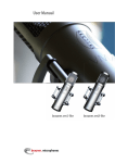
Power+
Speed drive
User manual
NO POWER
& SIGNAL
CABLES
TOGETHER
READ CAREFULLY IN THE TEXT!
Integrated Control Solutions & Energy Savings
ENG
WARNINGS
NO POWER
& SIGNAL
CABLES
TOGETHER
CAREL bases the development of its products on decades of experience
in HVAC, on the continuous investments in technological innovations
to products, procedures and strict quality processes with in-circuit and
functional testing on 100% of its products, and on the most innovative
production technology available on the market. CAREL and its subsidiaries
nonetheless cannot guarantee that all the aspects of the product and the
software included with the product respond to the requirements of the
final application, despite the product being developed according to startof-the-art techniques.
The customer (manufacturer, developer or installer of the final equipment)
accepts all liability and risk relating to the configuration of the product
in order to reach the expected results in relation to the specific final
installation and/or equipment.
CAREL may, based on specific agreements, act as a consultant for the
positive commissioning of the final unit/application, however in no case
does it accept liability for the correct operation of the final equipment/
system.
READ CAREFULLY IN THE TEXT!
Approval:
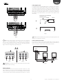
WARNING: separate as much as possible the probe
and digital input signal cables from the cables carrying
inductive loads and power cables to avoid possible
electromagnetic disturbance. Never run power cables
(including the electrical panel wiring) and signal cables
in the same conduits
the quality and safety of CAREL products are
guaranteed by the ISO 9001 certified design and
production system, as well as by the
marks.
The CAREL product is a state-of-the-art product, whose operation is
specified in the technical documentation supplied with the product or
can be downloaded, even prior to purchase, from the website www.CAREL.
com.
Each CAREL product, in relation to its advanced level of technology,
requires setup / configuration / programming / commissioning to be
able to operate in the best possible way for the specific application. The
failure to complete such operations, which are required/indicated in the
user manual, may cause the final product to malfunction; CAREL accepts
no liability in such cases.
Only qualified personnel may install or carry out technical service on the
product.
The customer must only use the product in the manner described in the
documentation relating to the product.
and
DISPOSAL
INFORMATION FOR USERS ON THE CORRECT HANDLING OF WASTE
ELECTRICAL AND ELECTRONIC EQUIPMENT (WEEE)
In reference to European Union directive 2002/96/EC issued on 27 January
2003 and the related national legislation, please note that:
• WEEE cannot be disposed of as municipal waste and such waste must be
collected and disposed of separately;
• the public or private waste collection systems defined by local legislation
must be used. In addition, the equipment can be returned to the
distributor at the end of its working life when buying new equipment;
• the equipment may contain hazardous substances: the improper use or
• incorrect disposal of such may have negative effects on human health
and on the environment;
• the symbol (crossed-out wheeled bin) shown on the product or on the
• packaging and on the instruction sheet indicates that the equipment
has been introduced onto the market after 13 August 2005 and that it
must be disposed of separately;
• in the event of illegal disposal of electrical and electronic waste, the
penalties are specified by local waste disposal legislation.
In addition to observing any further warnings described in this manual, the
following warnings must be heeded for all CAREL products:
• Prevent the electronic circuits from getting wet. Rain, humidity and
all types of liquids or condensate contain corrosive minerals that may
damage the electronic circuits. In any case, the product should be
used or stored in environments that comply with the temperature and
humidity limits specified in the manual.
• Do not install the device in particularly hot environments. Too high
temperatures may reduce the life of electronic devices, damage them
and deform or melt the plastic parts. In any case, the product should be
used or stored in environments that comply with the temperature and
humidity limits specified in the manual.
• Do not attempt to open the device in any way other than described in
the manual.
• Do not drop, hit or shake the device, as the internal circuits and
mechanisms may be irreparably damaged.
• Do not use corrosive chemicals, solvents or aggressive detergents to
clean the device.
• Do not use the product for applications other than those specified in
the technical manual.
All of the above suggestions likewise apply to the controllers, serial boards,
programming keys or any other accessory in the CAREL product portfolio.
CAREL adopts a policy of continual development. Consequently, CAREL
reserves the right to make changes and improvements to any product
described in this document without prior warning.
The technical specifications shown in the manual may be changed without
prior warning.
SYMBOLS
The liability of CAREL in relation to its products is specified in the CAREL
general contract conditions, available on the websie www.CAREL.com and/
or by specific agreements with customers; specifically, to the extent where
allowed by applicable legislation, in no case will CAREL, its employees
or subsidiaries be liable for any lost earnings or sales, losses of data and
information, costs of replacement goods or services, damage to things
or people, downtime or any direct, indirect, incidental, actual, punitive,
exemplary, special or consequential damage of any kind whatsoever,
whether contractual, extra-contractual or due to negligence, or any other
liabilities deriving from the installation, use or impossibility to use the
product, even if CAREL or its subsidiaries are warned of the possibility of
such damage.
Dangerous voltage
Caution, hot surface
Important: brings critical subjects regarding use of the product to the user’s
attention
Note: when attention must be given to subjects of relevant importance, in
particular regarding practical use of the various product functionality.
3
“Power+” +0300050EN - rel. 2.3 - 08.06.2012
ENG
Content
1. WARNINGS
7. PARAMETERS TABLE
7
7.1 Parameters table ...........................................................................................26
7.2 Commands .....................................................................................................29
7.3 Status variables ..............................................................................................29
1.1 General warnings ............................................................................................ 7
1.2 Fundamental safety rules .............................................................................. 7
2. INTRODUCTION
8
8. ALARMS
2.1 Functions and main features ........................................................................ 8
2.2 Models ............................................................................................................... 8
3. INSTALLATION
3.1
3.2
3.3
3.4
3.5
3.6
3.7
3.8
3.9
3.10
3.11
3.12
3.13
3.14
4.1
4.2
4.3
4.4
4.5
4.6
9
31
Types of alarm ............................................................................................... 31
Alarms log ....................................................................................................... 31
Alarms table ................................................................................................... 31
Modbus® communication error code ....................................................32
Motor overtemperature ...............................................................................32
Serial communication interruption ...........................................................32
Alarms signal with relay ...............................................................................32
9. TECHNICAL SPECIFICATIONS
33
9.1 Rated current values ...................................................................................33
10. APPENDIX
34
10.1 Conversion formulas ....................................................................................34
10.2 Conversion table ...........................................................................................34
18
Configuration ................................................................................................. 18
A - PM motor (brushless) ........................................................................... 18
B - Asynchronous motor with vector control.......................................... 19
C - Asynchronous motor with V/f control................................................20
Autotuning ......................................................................................................20
Controls before commissioning ................................................................20
5. FUNCTIONS
5.1
5.2
5.3
5.4
5.5
5.6
5.7
5.8
5.9
5.10
5.11
5.12
5.13
5.14
5.15
8.1
8.2
8.3
8.4
8.5
8.6
8.7
Identification..................................................................................................... 9
Structure ............................................................................................................ 9
Dimensions ...................................................................................................... 9
Drilling and assembly..................................................................................... 9
Cooling ............................................................................................................ 10
Electrical installation ..................................................................................... 10
Conformity to EMC standards .................................................................... 11
Electrical connections ................................................................................... 11
Functional layouts ......................................................................................... 14
General connection diagram ...................................................................... 15
Power+ Coldplate models ......................................................................... 16
PFC coil............................................................................................................ 16
DC choke .........................................................................................................17
EMI filter ...........................................................................................................17
4. START-UP
26
21
Inputs and outputs ....................................................................................... 21
Relay configuration ....................................................................................... 21
Minimum and maximum output frequency ........................................... 21
Direction of rotation inversion ................................................................... 21
Speed profile .................................................................................................. 21
Speed profile: execution mode .................................................................22
Switching frequency .....................................................................................22
Stop mode ......................................................................................................22
Flying restart ...................................................................................................22
V/f control for asynchronous motor .........................................................22
Motor control on start-up............................................................................23
PI parameters .................................................................................................23
Commands .....................................................................................................23
Status variables ..............................................................................................24
Modbus® Commands ................................................................................24
6. PROTECTIONS
25
6.1 Skip frequency ...............................................................................................25
6.2 Automatic reduction of the switching frequency ...................................25
6.3 Automatic reduction of motor speed .......................................................25
5
“Power+” +0300050EN - rel. 2.3 - 08.06.2012
ENG
“Power+” +0300050EN - rel. 2.3 - 08.06.2012
6
ENG
1. WARNINGS
1.1 General warnings
• The Power+ drive must be fitted by professionally qualified personnel on a
complete unit or system as part of a fixed installation.
• This device features dangerous voltages, and consequently failure to
observe the instructions contained in this user manual may cause serious
harm to people and damage to things.
• The system design, installation, commissioning and maintenance of
the drive are operations that are reserved solely for qualified personnel,
who understand all of the safety warnings, installation, operating and
maintenance instructions contained in this user manual code +0300050EN,
available, including prior to purchase, at www.carel.com, under “Literature”.
1.2 Fundamental safety rules
Before performing any maintenance work:
•
disconnect Power+ and external control circuits from the power
supply, moving the main system switch to “off ”; wait at least 5 minutes;
•
always check, using a suitable multimeter, that there is no dangerous
voltage across the terminals;
•
always make sure the motor has stopped completely. Motors that
are still freely rotating may produce dangerous voltages at the Power+
terminals, even when this is disconnected from the power supply;
•
check the temperature of the heat sink: coming in contact with the
heat sink may cause burns.
When Power+ is connected to the mains, motor terminals U, V, W are
live, even if the motor is not running.
Do not measure insulation resistance or dielectric rigidity directly on
Power+, or with Power+ connected.
The control terminals are isolated from the mains voltage. Nonetheless,
the relay outputs may have a dangerous control voltage even when Power+
is not connected to the mains.
The level of safety provided by the enabling inputs on Power+
(excluding the “Safety Torque Off ” input when used in compliance with the
standards) is not sufficient in critical applications without adopting
further independent safety measures. For all applications where malfunctions
may cause serious harm to people and damage to things, the risks must be
assessed and additional safety measures adopted
Observe all the general and local safety standards concerning
installations of high voltage devices, as well as the regulations for the correct
use of the personal protective equipment.
Use this device only for the purposes specified by the manufacturer.
Do not make any modifications or replace any components unless
recommended by the manufacturer, as these actions may cause fire, electric
shock or other damage.
7
“Power+” +0300050EN - rel. 2.3 - 08.06.2012
ENG
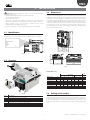
2. INTRODUCTION
Power+ is a drive designed to control compressors with sensorless-brushless
permanent magnet (PM) motors (BLDC/BLAC) or asynchronous induction
motors. For the latter, vector or V/f control can be selected. The drives can
also be used in some applications with fans and pumps, and consequently
the device offers flexible use in the air-conditioning and refrigeration
sectors. It is fitted for panel installation or with heat sink outside of the panel.
Configuration and programming, as well as the Run/stop controls and speed
reference, are managed by a CAREL pCO controller or any controller device
via RS485 serial connection using the Modbus® protocol in master mode.
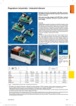
2.2 Models
The models differ due to power supply and rated output current as well as
for type of cooling:
• traditional with forced air cooled finned heatsink – frame sizes 1 and 2.
• coldplate, with plate for coupling to auxiliary cooling circuit devices (not
supplied) – frame size 3
Code
PSD0012200
PSD0012A00
PSD0016200
PSD00162A0
PSD0014400
PSD00144A0
PSD0022400
PSD00224A0
To suppress current harmonics:
• on single-phase models, during installation a toroidal coil, supplied with
the drive, needs to be connected for active power factor correction (PFC);
• on three-phase models, connection of a DC choke is optional (available for
purchase as an accessory), if compliance with EN61000-3-12 is required.
Power supply
200…240Vac ± 10%, 1~
200…240Vac ± 10%, 1~
380…480 Vac ± 10%, 3~
380…480 Vac ± 10%, 3~
Nominal output Frame size (*)
current (A)
1
12
3
2
16
3
1
14.5/18
3
2
22.5
3
Tab. 2.a
(*) For the dimensions see par. 3.3 and 3.11
2.1 Functions and main features
For Coldplate models PSD00***A* see paragraph 3.11
In summary:
• compact dimensions for assembly in electrical panels;
• operation at ambient temperatures from -20 to 60°C;
• can be installed in residential and industrial environments;
• connection via serial network to Master programmable controller;
• network address can be configured by setting the dipswitches directly on
the drive;
• can control various types of compressors;
• safety digital input (Safety Torque Off );
• dedicated input for PTC thermistor or thermostat to monitor motor
overtemperature;
• panel installation or with heat sink outside of the panel, to optimize the
dissipation of heat inside the electrical panel;
• electrical connections can be made without needing to remove the plastic
cover;
• programmable acceleration curve to adapt to the required specifications
when starting compressor;
• high switching frequency to limit motor noise;
• detailed information on drive status via numerous read-only variables;
• protection functions for the drive (short-circuit, overcurrent, earth fault,
overvoltage and undervoltage on the bus, overtemperature), motor
(overtemperature and limitation of current delivered) and system (Safety
Torque Off input, communication failure).
“Power+” +0300050EN - rel. 2.3 - 08.06.2012
Accessories
Code
PSACH10000
PSACH10100
PSARF10000
Description
DC choke for PSD00144*0
DC choke for PSD00224*0
EMI filter CNW102.1/30 for PSD00**2*0
Tab. 2.b
8
ENG
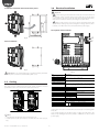
3. INSTALLATION
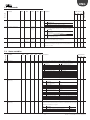
3.3 Dimensions
Important: avoid installing the drive in environments with the
following characteristics:
• relative humidity higher than 95% or with condensation;
• strong vibrations or knocks;
• exposure to water sprays;
• exposure to aggressive and polluting atmospheres (e.g.: sulphur and
ammonia fumes, saline mist, smoke) to avoid corrosion and/or oxidation;
• strong magnetic and/or radio frequency interference (thus avoid
installation near transmitting antennae);
• exposure of the drive to direct sunlight and the elements in general.
The overall dimensions of the drive vary based on the size of the heat sink (size
1 and size 2 for models with forced air cooled finned heatsink and size 3 for
Coldplate models) and the type of assembly (panel or with heat sink outside
of the panel, see the paragraph on “Drilling and assembly”), as the position
of the fastening brackets affects the total height. The side brackets are only
needed for assembly with the heat sink outside of the panel. For single-phase
models, the dimensions increase because the coil for power factor control
circuit (PFC) also needs to be connected. For three-phase models space may
also be required for a DC choke for limiting the power factor. All the brackets
have a 5.5 mm diameter hole.
3.1 Identification
Power+ is identified by a rating plate located on the top of the device, which
describes the code, serial number, production date and revision number.
B
A
PSD0********
S/N
Input:
Output:
Date:
Rev:
80
163,8
C
D
Fig. 3.a
7,5
75
3.2 Structure
E
240,8
125
H
Fig. 3.c
DIMENSIONS (mm)
G
F
A
B
Model / size
PSD0012200 / 1
PSD0016200 / 2
PSD0014400 / 1
PSD0022400 / 2
PSD00122A0 / 3
PSD00162A0 / 3
PSD00144A0 / 3
PSD00224A0 / 3
C
E
C
Assembly
Heat sink outside panel
E
A
B
C
D
77 299,2 289,2 192,3 202,3
107,9 299,2 289,2 192,3 202,3
77 299,2 289,2 192,3 202,3
107,9 299,2 289,2 192,3 202,3
12 299,2 289,2 192,3 202,3
12 299,2 289,2 192,3 202,3
12 299,2 289,2 192,3 202,3
12 299,2 289,2 192,3 202,3
Weight
Panel
A
279,3
279,3
279,3
279,3
-
B
269,3
269,3
269,3
269,3
-
(kg)
3,3
4,0
3,6
4,4
2,5
2,5
2,7
2,8
Tab. 3.b
D
Fig. 3.b
Ref.
A
B
C
D
E
F
G
H
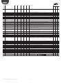
3.4 Drilling and assembly
Description
Terminal block for power connections
Terminal block for control connections
Fastening brackets
Cooling fan
PE
Microswitches for setting the network address
Operating status LED
Terminal block for PFC coil connection or optional DC choke
For installation with the heat sink outside of the panel, make a hole with
dimensions of the dashed rectangle, where the heat sink will be fi tted, and
holes for fastening the brackets. These are inserted in the slots between the
heat sink and the plastic cover. For panel installation, only use the top and
bottom brackets, which are inserted in the slots above and below the heat
sink.
Tab. 3.a
9
“Power+” +0300050EN - rel. 2.3 - 08.06.2012
ENG
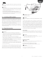
Installation with heat sink outside of the panel
3.6 Electrical installation
145,6
243
289,2
Important:
•
before carrying out any maintenance work, disconnect the drive and
the external control circuits from the power supply by moving the main
system switch to “off ”. Once power has been disconnected from the drive,
wait at least 5 minutes before disconnecting the electrical cables;
•
always make sure the motor has stopped completely. Motors that
are still freely rotating may produce dangerous voltages at the Power+
terminals, even when this is disconnected from the power supply.
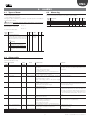
Description of the terminals
80
138
192,3
G
F
Fig. 3.d
Panel installation
C1
269,3
C2
E
L1/L L2/N L3
U
V
W
80
Fig. 3.e
Fig. 3.g
Important: in case of dismantling, do not grab the brackets, but rather
the “solid“ parts such as the heat sink and the plastic cover.
Ref.
L1/L, L2/N, L3
earth connection (*)
L1/L, L2/N
earth connection (*)
U, V, W
earth connection (*)
C1, C2
3.5 Cooling
All the Power+ drives, Coldplate models excluded, are fitted with cooling
fans. There must be sufficient air flow and air change inside the electrical
panel. Refer to table 9.1 for maximum heat dissipation values.
1
2
3
4
5
6
7
8
9, 10
E
F
G
≥ 200 mm
≥ 10 mm
Single-phase power supply input
Motor output
Terminals for connecting the PFC coil for single-phase
drives or optional DC choke for three-phase drives
0V
RX+/TX+
RS485/ModBus® connection
RX-/TXPTC Input
24Vdc
Auxiliary voltage
0V
STOa
Safety Torque Off digital input (**)
STOb
Relay output
PE
Microswitches for setting the network address
POWER = drive powered
Led
FAULT = active alarm
DATA
= communication active
Tab. 3.c
{
(*) The earth connections inside the drive are electrically connected together
and to PE.
(**) To enable the drive for operation, apply a voltage of 24 Vac/Vdc to the
Safety Torque Off digital input. The polarity is indifferent for direct current
power supply.
≥ 200 mm
Fig. 3.f
Note:
• on single-phase models leave space to fit the PFC coil;
• on three-phase models space may be needed to fit a DC choke (see par.
3.8).
“Power+” +0300050EN - rel. 2.3 - 08.06.2012
Description
Three-phase power supply input
10
ENG
Note: the control signals terminal unit 1...8 and the relay terminals unit
9, 10 are double isolated from each other and with respect to the power
terminal board.
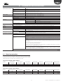
Vite / screw
M4
Important:
• in the European Union, all units that incorporate the drive must comply
with the Machinery Directive 2006/42/EC. Specifically, the manufacturer
of the unit is responsible for the installation of a main switch and the
conformity to standard EN 60204-1;
• for fixed installations according to IEC61800-5-1, a disconnect device is
required on the circuit between the power supply and the drive;
• only use permanently wired power input connections; the drive must be
earthed: the earth wire must be sized for the maximum fault current that is
normally limited by the fuses or a circuit breaker.
L1/L L2/N L3
U
V
W
7,5 mm MAX
Fig. 3.h
Important: the tightening torque is:
• power terminals: 1 Nm;
• control terminals: 0,5 Nm.
3.7 Conformity to EMC standards
Important:
In the unscrewing phase, do not force the screw further when it is fully
home.
Power+ is designed in compliance with the high EMC standards. All models
are supplied with an internal EMC filter, designed to reduce the emissions
taken towards the power supply line in conformity with harmonised European
Standards. It is the installer’s responsibility that the device or system within
which Power+ is incorporated is in compliance with the Standards in force
in the country of use. The Standard in force within the European Union is the
EMC 2004/108/EC Directive. Power+ is intended to be incorporated inside
fixed installation devices, only installed by specialised staff.
Conformity with the EMC Standard means that the indications given in the
“Electric connections” paragraph are respected and, as it also depends on
wiring topology, it must be checked on the final machine as envisioned by
the Final Product Standard.
3.8 Electrical connections
The drive must be earthed: to do this, use either the screw terminal (earth
symbol ), or the screw (PE symbol ) on the side of the heat sink, in accordance
with local standards in force. To minimise EMC problems, use a power cable
with earth wire included, connected to terminal . The power supply earth
must be connected directly to the earth bar in the electrical panel, without
branches to other devices; the earth wire size must be greater than or equal
to the phase wires; the earth impedance must be compliant with national
and local standards; in compliance with UL requirements, the protective
earth connections (PE) must be made using eyelet lugs. On single-phase
models, also connect the PFC coil. On three-phase models, where necessary
connect the optional DC choke in place of the jumper that closes terminals
C1 and C2. See the “Terminals C1 and C2” paragraph.
For installation proceed as shown below, with reference to the general
connection diagram (par. 3.10).
Power supply
Connect the power cables: for single-phase models connect the power
supply to terminals L1/L and L2/N, for three-phase models to terminals L1, L2,
L3; for the size of the cables and the type of fuses, see the table in paragraph
9.1.
Important:
the following warnings must be observed when connecting the drive:
• separate as much as possible the probe and digital input cables (at least 40
cm) from the power cables to avoid possible electromagnetic disturbance.
Never lay power cables (including the electrical panel cables) and probe
signal cables in the same conduits;
• the cables must be sized according to the table in paragraph 9.1;
• when the fuses are used, these must be chosen according to the data
shown in the table in paragraph 9.1, and must comply with the national
and local standards in force. In general, use type gG fuses for IEC and type
T for UL, with a blow time less than 0.5 s;
• when a magnetic circuit breaker (MCB) is used, it must be of type B, rated
according to the data shown in the table in paragraph 9.1;
• avoid installing cables connected to the control terminal block in the
immediate vicinity of power devices (contactors, circuit breakers, etc.).
Reduce the path of the cables as much as possible, and avoid spiral paths
that enclose power devices.
Important:
• do not connect the power supply to terminals U, V, W;
• make sure the voltage, frequency and number of phases in the power
supply match the ratings of the specific model.
Terminals C1 and C2
Important:
The use of terminals C1 and C2 depends on the model and differs based on
the type of power supply: single-phase or three-phase.
Models with 200/240 Vac single-phase power supply
Connect the PFC coil supplied with the drive to terminals C1 and C2.
Use cables rated to 90 °C, and if the temperature of the terminals exceeds 85
°C, use cables rated to 105 °C. Use cable terminals suitable for the terminals
and the cables used. Loosen each screw and insert the cable ends, then
tighten the screws and lightly tug the cables to check correct tightness. For
fork cable terminals, do not exceed the maximum width shown in the figure.
Important:
Never short-circuit terminals C1 and C2.
The PFC coil does not require connection to earth.
See paragraph 3.12 for dimensions of the PFC coil.
11
“Power+” +0300050EN - rel. 2.3 - 08.06.2012
ENG
Earth leakage current
Induttanza PFC
solo per modello monofase
As for all inverter devices, earth leakage current greater than 3,5mA may
occur. The drive is designed to produce the minimum possible leakage
current. The current depends on the length and the type of motor cable, the
effective switching frequency, the type of earth connection used and the
type of RFI filter installed.
PFC coil
for single-phase model only
C1
C2
If a residual-current circuit breaker (RCCB) is to be used, the following
conditions apply:
• it must be a type B device (suitable to protect the equipment against
leakage current with a DC component);
• Individual RCCBs should be used for each drive.
200mm
Fig. 3.i
Motor
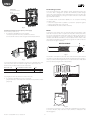
Models with 380/480 Vac three-phase power supply
There are two possible cases:
1. if compliance with EN61000-3-12 is required:
connect the optional DC choke to terminals C1 and C2.
Connect the DC choke to earth using the relevant metal terminal
Connect the motor power cable: use four-wire cable, the impedance of the
earth wire must be less than or equal to the impedance of the phase wires.
For the size and maximum length of the cable according to the model, see
the table in paragraph 9.1. To ensure conformity to the EMC directive, use
shielded cable with the shield that covers at least 85% of the surface of the
cable, with low impedance for high frequency signals. The cable can also be
laid in steel and copper cableways.
V
MOTOR CABLE
U
2m max
C1
C2
W
PE
Fig. 3.l
The shield is connected to both ends of the cable: the drive earth terminal
should be connected by twisting the shield. The twisted part must be left as
short as possible, and the length must not exceed five times the width. Earth
the motor directly using the drive earth terminal.
Fig. 3.j
To connect the DC choke to terminals C1 and C2, use a cable that is the same
size as the power cable. The maximum length of the cable must be 2 m.
The DC choke used depends on the size of the drive:
DC choke code
PSACH10000
PSACH10100
to be installed on Power+ drive
PSD0014400, PSD00144A0
PSD0022400, PSD00224A0
.
type
3mH, 20A
2mH, 25A
Tab. 3.d
L1/L L2/N L3
U
V W
1 23 4 5 678
910
See paragraph 3.13 for the dimensions of the DC choke
2. if compliance with EN61000-3-12 is not required:
jumper terminals C1 and C2 (the drive leaves the factory with C1 and C2
jumpered).
C1
C2
V
U
W
PE
Fig. 3.k
Fig. 3.m
Connect the motor phases so as to ensure the required direction of rotation:
to reverse direction, swap over two of U, V, W wires as indicated in the
following figures.
“Power+” +0300050EN - rel. 2.3 - 08.06.2012
12
ENG
Safety digital input
L1/L L2/N
L3
U
V
Connect the “Safety Torque Off ” digital input to a safety device (for example,
a maximum pressure switch) with normally closed voltage-free contact, in
series with an external 24 Vac/24 Vdc voltage source, without needing to
observe the polarity for direct current (ref. A). When the contact is open, the
drive stops operating, bypassing the software control. If the Safety Torque
Off function is not used, the input must be connected to the auxiliary 24
Vdc available on the terminal block, so as to enable correct operation of the
drive (ref. B).
W
Dispositivo di sicurezza NC
NC Safety device
24 Vdc
U V W
24 Vac
M
A
L1/L L2/N
L3
U
V
7
8
5
6
W
B
U V W
7
8
Fig. 3.q
M
Fig. 3.n
Note: IEC61508 standard requires that the power supply applied to the
safety input is isolated from the drive.
Note: Most general purpose asynchronous motors are wound for
operation on dual voltage supplies. This is indicated on the nameplate of
the motor. This operational voltage is normally selected when installing the
motor by selecting either Star or Delta connection. Star always gives the
higher of the two voltage ratings. Typical ratings are:
Serial network connection
For the serial connection use a three-wire shielded cable. For large networks,
install a 120 ohm ¼. W resistor between terminals 2 and 3 on the last drive or
device connected, to avoid possible communication problems.
pCO / building management system
GND
Tx/Rx+
Tx/Rx-
/
400V/230V
690V/400V
Schermo
Shield
U
V
Fig. 3.o
W
U
V
Power +
Power +
0V
Tx/Rx+
Tx/Rx-
RS485
Delta
0V
Tx/Rx+
Tx/Rx-
Star
1 2 3
1 2 3
R = 120 ohm
W
Fig. 3.p
Fig. 3.r
Important: do not turn on or OFF a switch between the drive and the
motor when the drive is running.
Motor protector
Connect a PTC thermistor motor protector to terminals 4 and 5: use a cable
with a minimum cross-section of 1 mm2; alternatively, a Klixon thermostat
can be connected (see the general connection diagram). The PTC thermistor
must be selected so that at activation temperature the resistance is > 2600 Ω.
13
“Power+” +0300050EN - rel. 2.3 - 08.06.2012
ENG
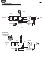
3.9 Functional layouts
The functional layouts show the PFC inductance to be mounted only in the
single-phase model and the DC choke where necessary fitted as an option
on three-phase models only.
Single-phase model
induttanza PFC
PFC coil
rettificatore
rectifier
C2
C1
Inverter IGBT
DC Bus
alimentazione
power supply
L
1~
N
1~
U
RFI
filter
V
PFC
3~
ventilatore
fan
alimentazione
power supply
motore
motor
W
controllo motore
motor control
DSP
Fig. 3.s
Three-phase model
reattanza DC opzionale
optional DC choke
C1
C2
rettificatore
rectifiers
Inverter IGBT
DC Bus
alimentazione
power supply
L1
3~
L3
L2
1~
U
RFI
filter
V
3~
ventilatore
fan
alimentazione
power supply
Fig. 3.t
“Power+” +0300050EN - rel. 2.3 - 08.06.2012
14
controllo motore
motor control
DSP
W
motore
motor
ENG
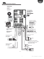
3.10 General connection diagram
Induttanza PFC
solo per modello
monofase
PFC coil
for single-phase
model only
Microinterruttori
indirizzi
Dip switches for
ON
power +
speed drive
C1
C2
12 34
C1
C2
C1
Connessione al 24 Vdc
ausiliari in caso di non
utilizzo della funzionalità
C2
PE
NO C
L1/L L2/N L3
U
V
W
123
Reattanza DC opzionale
solo per modello
trifase
4 5 6 7 8 9 10
9 10
Connection to auxiliary
24 Vdc supply when
function Safety Torque
Off is not used
123
4 5 6 7 8 9 10
segnale d’allarme/alarm signal
Uscita programmabile
Optional DC choke
for three-phase
model only
Programmable output
Free voltage contact (up to 240 Vac)
M
3
dispositivo di sicurezza
safety device
Alimentazione trifase
Three-phase AC
power supply
Fuse or
MCB
L1
L2
L3
PE
24 Vdc
24 Vac
Connessione con alimentazione
di sicurezza esterna (24 Vac o 24 Vdc)
Connection with safety external
supply (24Vac or 24Vdc)
L1/L L2/N
Alimentaz. monofase
Single-phase AC
Fuse or
power supply
PTC
MCB
L
N
PE
Klixon N.C.
Modbus®
pCO
Fig. 3.u
15
“Power+” +0300050EN - rel. 2.3 - 08.06.2012
ENG
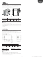
3.11 Power+ Coldplate models
Attention:
• Make sure that the cooling device is dimensioned and fixed to the plate
in a way to dissipate the heat while keeping the temperature of the plate
below 70°C in the various operating conditions and that the overheating
alarm does not intervene.
• Make sure that the cooling device does not cause the formation of
condensate on the inner surface of the plate.
• Clean the contact surfaces of the Power+ plate and of the coldplate and
ensure they couple perfectly.
• The use of thermal compound or similar product, between the contact
surfaces of the Power+ and the coldplate allows better heat coupling.
The Power+ Coldplate (PSD00***A0) models are the same as respective
standard Power+ models, with the unique difference that the finned heatsink
and fan are replaced by a flat aluminium plate.
The plate has threaded holes M5 for fixing an additional device with cooling
function (coldplate), typically using liquid refrigerant. The coldplate is the
user’s responsibility and is not supplied by Carel.
75
Dimensions
3.12 PFC coil
25
12
The PFC coil is supplied with the Power+ drive for models with single-phase
power supply (PSD00**2*0) and is complete with cables measuring 25 cm in
length for connection to the drive.
The coil envisions a central hole for fixing to the wall. Screw and relative
adapters for fixing are also supplied.
60
M5
240,8
1
60
70,8
289,2
2
A
25
A
26
75
3
26
10
127
A-A
Fig. 3.v
Fig. 3.x
Assembly
1
2
3
PFC coil
M4 x 80mm screw and washer
M4 plastic washers
1
C
B
2
3
A
Fig. 3.y
5
Power+ drive code
PSD0012200
PSD00122A0
PSD0016200
PSD00162A0
4
Fig. 3.w
1
2
3
4
5
Cooling device - coldplate (example)
Holes/screws to be used always
Holes/screws to be used with large coldplate
Hot spot (to be cooled)
Power+ plate
“Power+” +0300050EN - rel. 2.3 - 08.06.2012
16
A
83
Dimensions (mm)
B
C (diam)
63
6,3
Weight
(kg)
1,7
ENG
3.13 DC choke
The DC choke is an optional that can be supplied separately to be used with
the Power+ drives with three-phase power supply (PSD00**4*0) to reduce
the harmonic currents to the levels envisioned by EN61000-3-12.
The choke has four holes for fixing to the wall.
D
E
C
B
A
G
F
Fig. 3.z
DC choke code
PSACH10000
PSACH10100
A
B
Dimensions (mm)
C
D
E
F
86
96
98
94
84
G (diam)
Weight
(kg)
5
2,7
71
Attention:
• Position the choke as near as possible to the drive in a way to minimise
connection cable length (max 2m).
• For connection to the drive use cables with section at least equal to the
power supply cable.
• Envision the space necessary for connection of the cables to the choke
terminals.
3.14 EMI filter
The EMI filter is an optional that can be supplied separately to be used with
Power + drives with single-phase power supply (PSD00**2*0) to reduce the
emissions to the levels envisioned by EN61800-3 category C1.
The filter must be connected between the power supply and terminals L1/L,
L2/N and earth of the drive.
Fig. 3.aa
EMI filter code
L1
L2
Dimensions (mm)
L3
B1
B2
B3
H
D
Weight
(kg)
PSARF10000
(CNW102.1/30)
180
150
90
70
5
1,3
98
88
70
Technical specifications
Current
Voltage
Temperature
30A
250V
60°C
Leakage current
Connection by terminal
< 3,5mA
4mm2
Attention:
• Connect power supply cable and drive as shown on the label.
• Position the filter as near as possible to the drive in a way to minimise
connection cable length.
• Connect the filter metal casing to earth.
17
“Power+” +0300050EN - rel. 2.3 - 08.06.2012
ENG
4. START-UP
Important: Power+ can pilot various types of compressors with
permanent magnetic motors (PM) brushless BLDC/BLAC sensorless or
asynchronous induction motors. To set the parameters of a particular
compressor, consult the values indicated by CAREL in the document
“Power+: compressors parameters tables”, code +0300051IE, available, also
prior to purchase, upon request.
ON
OFF
12 34
4.1 Configuration
The configuration of the drive consists in setting the various types of
parameters that regard:
1. the network communication: network address, data communication
baudrate, data communication parity;
2. the selection of the type of motor control;
3. the motor plate data;
4. the motor electric data;
5. motor start-up;
6. the motor control in regenerative functioning mode (load deceleration
with high inertia);
7. the proportional and integral regulation (PI) of the speed.
Fig. 4.a
Dip-switch address
1
OFF
ON
OFF
…
ON
Dip-switches
2
3
OFF
OFF
OFF
OFF
ON
OFF
…
…
ON
ON
Address
Dip-switch
0
1
2
…
15
Tab. 4.c
4
OFF
OFF
OFF
…
ON
Important: modify the network address via the dip-switches only with
drive off.
If the motor electric data (e.g.. resistances, inductance) are not known or are
believed not to reflect the effective data (for example due to the length of
the motor cable), the Autotuning function can be used. See paragraph 4.5.
Mod. Description
add.
30 Data communication baudrate
0 = 9600 bit/s
1 = 19200 bit/s
31 Data communication parity and
stop bits
0 = none (2 stopbits),
1 = even (1 stopbits),
2 = odd (1 stopbits),
Note: once the communication parameters are set and the type of
motor and control selected, the setting of the parameters of points 3...7
depends on the type of motor.
Network communication
Def
Min
Max
U.M.
R/W
1
0
1
-
R/W
0
0
2
-
R/W
Network address
The configuration and the programming of the Power+ drive, as well as
the run/stop commands and the speed reference are managed by a CAREL
pCO control from any BMS (Building Management System) via RS485 serial
connection with ModBus® protocol. The ModBus® network address that can
be set from 1 to 247. This number is made up from the base address that can
be set from the parameter and the address of the 4 dip-switches present on
the drive, which goes from 0 to 15. By changing the base address in steps of
16, the entire interval can be covered.
Important: the modification of the “Communication baudrate” and
“Communication parity” parameters only becomes effective on the next
switch on or reset command.
The transmission speed can be selected between 9600 and 19200 bit/s. All
devices connected in the serial network must have the same communication
baudrate and the same data communication parity.
Communication baudrate/communication parity
Motor control mode setting
Mod. add.
32
121
120
Description
Base address
Dip-switch address
Network address
Def
1
-
Min
1
0
1
Max
232
15
247
U.M.
-
Tab. 4.d
Power+ allows to drive compressors with permanent magnetic motors (PM)
brushless BLDC/BLAC sensorless or asynchronous induction motors. For the
latter it is possible to select between vector or V/f control.
R/W
R/W
R
R
Tab. 4.a
Mod. Description
Def Min Max U.M. R/W
add.
0 Motor control mode
0
0
2
- R/W
0 = PM brushless motor
1 = asynchronous motor with vector control
2 = asynchronous motor with V/f control
Tab. 4.e
Important: the drive only reads the network address on switch on or
after a reset control
Dip-switch address
0
Base address=1
Network address
Below find the list of parameters to be set according to the type of motor and
control. Follow the steps described in paragraphs 4.2 or 4.3 or 4.4, on the basis
of the type of motor control selected.
1+0=1
...
15
1+15=16
4.2 A - PM motor (brushless)
Motor data plate
0
Base address=232
Frequency/voltage/rated current/power factor
The base frequency is the frequency at which the base voltage is applied.
Base frequency and base voltage are relative to a generic point in the
voltage/frequency curve specified in the motor data sheet. The rated current
is the current at full load. The power factor is not used in this motor, but it is
recommended to set it at 100 (=1.00) for future compatibility.
232+0=232
...
15
232+15=247
Tab. 4.b
The address of the dip-switches in the drive is set manually as indicated
below.
“Power+” +0300050EN - rel. 2.3 - 08.06.2012
18
ENG
Mod. Description
add.
1 Motor base frequency
Def
2
3
Motor base voltage
Motor rated current
4
Motor power factor (cos)
Min
Max
PI parameters for speed regulation
U.M. R/W
In applications with slow acceleration and deceleration times, as with
compressors, it is recommended to use default values or the values indicated
by CAREL depending on the motors/compressors available. For particular
applications, consult CAREL.
500
250
5000 0.1Hz R/W
(50.0Hz) (25.0Hz) (500.0Hz)
230/400
25
250/500
V
R/W
Rated
(*)
(*)
0.1A R/W
current (*)
100
0/50
100
0.01 R/W
(1.00)
(0.5)
(1.00)
Tab. 4.f
Mod. Description
add.
55 Speed loop: Kp
(*) Values are model dependent. See chapter 7 “PARAMETERS TABLE”.
56
Speed loop: Ti
Def
250
(25.0%)
500
(0.5s)
Min
Max
1
2000
(0.1%) (200.0%)
1
1000
(0.001s)
(1s)
U.M.
R/W
0.1%
R/W
1ms
R/W
Tab. 4.k
Important: the base frequency is used as reference for the parameter:
• max frequency for starting current.
4.3
Note: see the Appendix for the frequency to the revolution speed
conversion formulas, related to the number of motor poles.
Motor data plate
Maximum motor current
The maximum motor current in the case of the compressor must be set
at 1000(=100.0%): as there is no necessity for quick accelerations, no peak
currents must be envisioned.
Mod.
Description
add.
5 Maximum output
current
Def
Min
1000
(100.0%)
0
Max
U.M.
Frequency/voltage/rated current/power factor
The base frequency is the frequency at which the nominal voltage is applied.
If current peaks are necessary, the rated current of the motor must be lower
enough that the drive rated current. The power factor is the rated cos of
the motor.
R/W
Mod. Description
add.
1 Motor base frequency
2000
0.1% Motor R/W
(200.0%) rated current
Tab. 4.g
Motor electric data
The stator resistance is the resistance of the stator windings, measured
between phase and phase. In the mathematical model of the motor, Ld and
Lq are the inductance used in the reference system (d,q) rotating at rotor
speed.It is recommended to use the values indicated by CAREL depending
on the motors/compressors available. If the Autotuning is performed, these
parameters are set automatically at the end of the procedure on the basis of
the measurements detected.
Mod.
add.
46
48
50
Description
Def
Min
Max
0
0
0
0
0
0
38500
6130
6130
Stator resistance
Stator inductance/Ld
Lq inductance
58
Maximum frequency
for starting current
Min
100
200
(20..0%)
0
0
0
0
Max
Motor power factor
(cos)
U.M.
R/W
500
250
5000
0.1Hz
(50.0Hz) (25.0Hz) (500.0Hz)
230/400
25
250/500
V
Rated
(*)
(*)
0.1A
current (*)
100
0/50
100
0.01
(1.00)
(0.5)
(1.00)
R/W
R/W
R/W
R/W
Note: see the Appendix for the frequency to the revolution speed
conversion formulas, related to the number of motor poles.
0.001ohm R/W
0.1mH
R/W
0.1mH
R/W
Tab. 4.h
Maximum motor current
If current peaks are necessary, set the “Maximum output current” a value
equivalent to the drive rated current.
Mod. Description
add.
5 Maximum output current
U.M.
R/W
Max
U.M.
R/W
0
2000
(200.0%)
2000
(200.0%)
0.1% Motor
rated curr.
0.1% Motor
rated curr.
R/W
Min
1000
(100.0%)
0
Max
U.M.
R/W
2000
0.1%
R/W
(200.0%) Motor rated
current
Tab. 4.m
They are values that are difficult to trace in the motors datasheets. It is
recommended to use the values indicated by CAREL depending on the
motors/compressors available. If the Autotuning is performed, these
parameters are set automatically at the end of the procedure on the basis of
the measurements detected.
30000
ms
R/W
1000
0.1% Motor
R/W
(100.0%)
rated curr.
1000
0.1% Motor
R/W
(100.0%) rated frequency
Tab. 4.i
Min
Def
Motor electric data
Mod. Description
add.
45 Motor magnetizing current
It is recommended to use the default values. Typically in the application with
compressors, the regenerative functioning mode never occurs. For particular
applications, consult CAREL.
0
4
Max
R/W
U.M.
Motor control in regenerative functioning mode
Mod. Description
Def
add.
53 Regeneration current 1000
limit
(100.0%)
54 Overvoltage control
100
current limit
(10.0%)
Motor base voltage
Motor rated current
Min
(*) Values are model dependent. See chapter 7 “PARAMETERS TABLE”.
These parameters optimise the initial start-up phase of the motor and the
relative estimate of the position and the motor speed. It is recommended to
use the values indicated by CAREL depending on the motors/compressors
available. See paragraph 5.11 for the meaning of the parameters.
Def
2
3
Def
Tab. 4.l
Motor start-up
Mod.
Description
add.
51 Magnetizing time
57 Starting current
B - Asynchronous motor with vector control
46
47
48
49
Stator resistance
Rotor resistance
Stator inductance/Ld
Leakage factor
Def
Min
0
0
0
0
0
0
0
0
0
0
Max
U.M.
Motor rated 0.1A
current
38500
mΩ
38500
mΩ
6130
0.1mH
250 (0.25)
0.01
R/W
R/W
R/W
R/W
R/W
R/W
Tab. 4.n
R/W
Tab. 4.j
19
“Power+” +0300050EN - rel. 2.3 - 08.06.2012
ENG
Motor start-up
Motor start-up
These parameters optimise the initial start-up phase of the motor and the
relative estimate of the position and the rotor speed. It is recommended to use
the values indicated by CAREL depending on the motors/compressors available.
These parameters optimise the initial start-up phase of the motor by adapting
the V/f feature on the basis of the particular application, in order to improve
performance at low speeds.
Mod. Description
add.
51 Magnetizing time
57 Starting current
58
Maximum frequency
for starting current
Def
Min
100
200
(20.0%)
0
0
0
Max
U.M.
R/W
Mod. Description
add.
35 V/f boost voltage
30000
ms
R/W
1000
0.1%
R/W
(100.0%)
1000
0.1%
R/W
(100.0%) Motor base
frequency
Tab. 4.o
0
Def
Min
Max
0
0
250
(25.0%)
36
V/f frequency adjustment
0
0
37
V/f voltage adjustment
0
0
54
Overvoltage control
current limit
Min
1000
(100.0%)
0
100
(10.0%)
0
Max
U.M.
R/W
2000
0.1%
R/W
(200.0%) Motor rated
current
2000
0.1%
R/W
(200.0%) Motor rated
current
Tab. 4.p
56
Speed loop: Ti
250
(25.0%)
500
Min
Max
1
2000
(0.1%) (200.0%)
1
1000
U.M.
R/W
0.1%
R/W
ms
R/W
Tab. 4.q
Autotuning consists in a measurement cycle, which can last about 1
minute, at the end of which the electric data of the motor are measured
and memorised in the respective parameters. To perform Autotuning, set
the “Autotuning” parameter at 1. At the end, the parameter is automatically
zeroed. The type of measure and the values memorised depend on the type
of motor control selected. See the following tables. If this is unsuccessful,
check the alarm 15. It is therefore necessary to repeat the procedure or search
for the data requested in order to introduce them directly.
Motor data plate
Frequency/voltage/rated current/power factor
The base frequency is the frequency at which the maximum voltage is applied.
The rated voltage is the maximum voltage applied to the motor. If current
peaks are necessary, the rated current of the motor must be lower enough that
the drive rated current. The Power factor is the rated cos of the motor.
2
3
Motor base voltage
Motor rated current
4
Motor power factor
(cos
Def
Min
Max
500
250
5000
(50.0Hz) (25.0Hz) (500.0Hz)
230/400
25
250/500
Rated
(*)
(*)
current (*)
100
0/50
100
(1.00)
(0.5)
(1.00)
U.M.
R/W
0.1Hz
R/W
V
0.1A
R/W
R/W
0.01
R/W
(*) Values are model dependent. See chapter 7 “PARAMETERS TABLE”.
“Power+” +0300050EN - rel. 2.3 - 08.06.2012
Max
U.M.
0
0
1
-
Mod. Description
add.
45 Motor magnetizing
current
46 Stator resistance
47 Rotor resistance
48 Ls stator inductance or
Ld inductance
49 Leakage factor
50 Lq inductance
Asynchronous
vect.
YES
R/W
PM
Brushless
NO(0)
Asynchronous
V/f
NO
YES
NO(0)
YES, Ld
YES
YES
YES, Ls
YES
NO
NO
NO(0)
YES
YES
NO(0)
NO
NO
Tab. 4.v
start of the procedure, the motor must be at a standstill;
• the end of the Autotuning procedure is signalled by the “Autotuning”
parameter and from bit7 of the “Status register”, which are automatically
taken back to 0.
Tab. 4.r
4.6 Controls before commissioning
Before commissioning, check that:
• the drive output current is greater than or equal to the rated current or the
maximum envisioned for the motor;
• the work voltage range is correct
• the section of the power supply cables is correct;
• the maximum section and length of the motor cables is correct and that
they are connected in compliance with the wiring diagrams;
• all of the control inputs are connected correctly.
No parameter has to be set. If Autotuning is performed, the “stator resistance”
parameter is set automatically at the end of the Autotuning procedure on the
basis of the measurements detected, also if its value is not used.
Min Max U.M.
0 38500 mΩ
Min
Important:
Motor electric data
Def
0
Def
• Autotuning can only be performed when a motor is connected. At the
Note: see the Appendix for the frequency to the revolution speed
conversion formulas, related to the number of motor poles.
Mod. add. Description
46
Stator resistance
Mod. Description
add.
103 Autotuning 0/1=not active/start
R/W
Tab. 4.u
Below a summary table with the electric data estimated according to the
type of motor. Where indicated at the end of the procedure, the parameters
are set at zero (0).
4.4 C - Asynchronous motor with V/f control
Mod. Description
add.
1 Motor base frequency
R/W
4.5 Autotuning
In applications with slow acceleration and deceleration times, as with
compressors, it is recommended to use default values or the values indicated
by CAREL depending on the motors/compressors available. For particular
applications, consult CAREL.
Def
R/W
Note: In the case of asynchronous motor with V/f control, the parameters
loose meaning for the control of the motor in regenerative functioning mode
and the PI parameters for the speed control.
PI parameters for speed regulation
Mod. Description
add.
55 Speed loop: Kp
R/W
Tab. 4.t
It is recommended to use the default values. Typically in the applications with
compressors, the regenerative functioning mode never occurs. For particular
applications, consult CAREL.
Def
R/W
0.1%
Motor base
voltage
1000
0.1%
(100.0%) Motor base
frequency
1000
0.1%
(100.0%) Motor base
voltage
Motor control in regenerative functioning mode
Mod. Description
add.
53 Regeneration current
limit
U.M.
R/W
R/W
Tab. 4.s
20
ENG
5. FUNCTIONS
5.1 Inputs and outputs
5.4 Direction of rotation inversion
During drive commissioning, in order to change the direction of rotation of
the motor, it is possible to swap over two of U, V, W wires. In the event of
application with compressors, there is only one motor rotation direction. In
other cases it is possible also to enable the reverse direction of rotation with
the relative parameter.
Inputs
The inputs include:
1. the single or three-phase power supply, depending on the model, which
must be connected selecting suitable cables and fuses according to the
table in paragraph 9.1;
2. the “Safety Torque Off ” safety digital input, to which an alternating or
direct voltage source is connected along with a safety device. See the
main connection layout;
3. the PTC thermistor for motor overtemperature protection. Must be
selected for motor protection and in a way that at the alarm temperature
the resistance is > 2600 ohm.
Mod. Description
add.
8 Reverse speed enable 0/1 = no/yes
Def
Min
Max
U.M.
R/W
0
0
1
-
R/W
Tab. 5.c
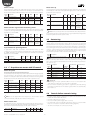
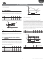
5.5 Speed profile
Important: in order to use the PTC input, the motor overtemperature
alarm must be enabled. See the paragraph 8.5.
Power+ has been designed with a programmable speed profile for adaptation
to the features requested on compressor start-up. Once the speed profile has
been selected it is also possible to establish the method of execution. The
profile is designed by three frequencies (f1, f2, f3), which must be reached
with three linear ramp trends, defined via three accelerations (a1, a2, a3).
Once the frequency fi (i=1, 2, 3) has been reached, the frequency value
remains for the time ti (i=1, 2, 3). Regarding decrease in speed, it is possible to
set just one deceleration.
Outputs
The drive outputs include:
1. the motor output, to which the cables must be connected, which are
dimensioned according to the table in paragraph 9.1;
2. the relay output.
f (Hz)
a4
f3
5.2 Relay configuration
f2
The relay function can be programmed and can indicate a functioning
condition of the drive or an alarm. See the chapter 8 “ALARMS” for the latter
case. The relay contact closes if the corresponding event occurs.
f1
Mod. Description
add.
26 Relay configuration
0: drive in alarm
1: fan running
2: drive overtemperature alarm
3: motor overtemperature alarm
4: motor overload alarm
5: overvoltage alarm
6: undervoltage alarm
7: speed derating in progress
8: motor running
Def
Min
Max
U.M.
R/W
0
0
8
-
R/W
t1
Fig. 5.a
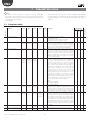
Mod.
add.
12
13
14
15
16
17
18
19
20
21
23
5.3 Minimum and maximum output
frequency
The parameters allow to set the minimum and maximum limit for the drive
output frequency. The frequency set point must also be within the limits
fixed by minimum and maximum frequency, otherwise it is not accepted.
Min
0
0
0
0
Max
U.M.
t
t3
t2
Key
f1/ f2/ f3
a1/a2/a3/a4
t1/ t2 /t3
Def
a2
a1
Tab. 5.a
Mod. Description
add.
6 Maximum output frequency
7 Minimum output frequency
a3
f
t
Frequency 1/2/3
Acceleration 1/2/3/4
Delay 1/2/3
Frequency
Time
Description
Def
Min
Max
U.M.
R/W
Speed profile: frequency 1
Speed profile: frequency 2
Speed profile: frequency 3
Speed profile: acceleration 1
Speed profile: acceleration 2
Speed profile: acceleration 3
Speed profile: acceleration 4
Speed profile: stand-by time 1
Speed profile: delay 2
Speed profile: delay 3
Speed profile: deceleration
0
0
0
60
60
60
60
0
0
0
60
0
0
0
0
0
0
0
0
0
0
0
5000
5000
5000
500
500
500
500
600
600
600
500
0.1Hz
0.1Hz
0.1Hz
0.1Hz/s
0.1Hz/s
0.1Hz/s
0.1Hz/s
s
s
s
0.1Hz/s
R/W
R/W
R/W
R/W
R/W
R/W
R/W
R/W
R/W
R/W
R/W
Tab. 5.d
Note: it is recommended to use the values indicated by CAREL in
relation to the compressor used, as they guarantee the functioning mode
specified by the manufacturer. Alternatively it is possible to set a simple profile
(f2=f3=Fmax; t1=t2=t3=0; a2=a3=a4=maximum acceleration allowed) and
refer management of the accelerations and delay times to the external
control. However, in this case it is necessary to keep the values of a1 and f1
indicated by CAREL, as they are critical for the compressor start-up phase.
R/W
5000 0.1Hz R/W
5000 0.1Hz R/W
Tab. 5.b
21
“Power+” +0300050EN - rel. 2.3 - 08.06.2012
ENG
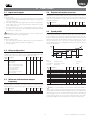
5.6 Speed profile: execution mode
5.7 Switching frequency
It is possible to define the execution mode of the speed profile with bit0, i.e.
if the individual delays must be performed just one time or if they must be
carried out every time the frequency set point exceeds one of the f1, f2, f3
frequencies. If the frequency set point is decreased, the deceleration set is
respected.
The parameter allows to set the switching frequency of the IGBT (Insulated
Gate Bipolar Transistor). During functioning the switching frequency can
decrease to protect the drive from overheating. It can be displayed with the
oprating switching frequency. See the chapter 6 “PROTECTIONS” .
Mod. Description
add.
22 Speed profile: execution mode (2 bit
parameter)
bit meaning
0/1
0
delay
always/only once at
execution
every start-up
1
force freq. 2 no/at start-up
Mod. Description
add.
24 Switching frequency
0 = 4kHz, 1 = 6kHz, 2 = 8kHz
124 Operating switching frequency
0=4kHz, 1=6kHz, 2= 8kHz
Def Min Max U.M. R/W
3
0
3
-
R/W
Def
Min
Max
U.M.
R/W
0
0
2
-
R/W
-
0
2
-
R
Tab. 5.g
Tab. 5.e
5.8 Stop mode
The motor stops after the Stop command has been given (see “Commands”
paragraph). In the ramp stop the speed of the motor decreases according
to the fixed deceleration parameter. In stop due to inertia, the motor stops
without any control by the drive.
Note: if the bit0=1 and the frequency set point is between frequency
2 and frequency 3, the speed profile will be performed respecting delays t1
and t2. If the frequency set point successively decreases to a value below
f2, the frequency is reached with the deceleration defined at the relative
parameter. If the frequency set point finally increases to a frequency value
greater than f3, only delay t3 is respected.
Mod. Description
add.
33 Stop mode
0 = ramp
1 = coast
f (Hz)
Def
Min
Max
U.M.
R/W
1
0
1
-
R/W
Tab. 5.h
a4
f3
setpoint
d
a3
f2
a3
5.9 Flying restart
a2
Power+ has the speed hitch function, useful whenever the RUN command is
given with motor rotating. Once the rotation frequency has been identified,
the output frequency will be increased/decreased to the frequency set point
on the basis of the established acceleration/deceleration parameters.
a2
f1
a1
t
t1
t2
t3
Mod. Description
add.
34 Flying restart 0/1=no/yes
Fig. 5.b
Key
f1/ f2/ f3
a1/a2/a3/a4
t1/ t2 /t3
f
t
Characteristic frequency 1/2/3
Deceleration/ Acceleration 1/2/3/4
Delay 1/2/3
Def
Min
Max
U.M.
R/W
0
0
1
-
R/W
Tab. 5.i
Frequency
Time
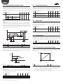
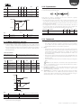
5.10 V/f control for asynchronous motor
The bit1 is considered only if the frequency set point on start-up is lower than
frequency 2 of the profile. If bit1=1, frequency 2 is always reached on start-up
respecting delays t1 and t2. The frequency set point is then reached with the
deceleration defined by the relative parameter.
In the V/f control, the motor voltage varies linearly with the frequency in the
flow area constant from 0 Hz to the point where the rated voltage is applied
to the motor.
Un (V)
I+]
f2
setpoint
d
a2
f1
a1
t1
W
t2
fn
Fig. 5.d
Fig. 5.c
Key
Key
f1/ f2
a1/a2
t1/ t2
f
t
d
Frequency 1/2
Acceleration 1/2
Delay 1/2
Un
Frequency
Time
Deceleration
Description
Motor frequency
Pre-ramp frequency set point
Post-ramp frequency set point
“Power+” +0300050EN - rel. 2.3 - 08.06.2012
Def
Min
Max
U.M.
R/W
-
-
-
0.1Hz
0.1Hz
0.1Hz
R
R
R
Tab. 5.f
rated voltage
fn
Rated frequency
The curve can be programmed, by inserting:
1. an increase in starting torque. The boost voltage is applied at frequency 0
for the time set at the “Magnetizing time” parameter, to then drop to zero
in correspondence with the frequency adjustment.
2. a programmable adjustment point, to adapt the application curve better.
Note:during execution of the acceleration/deceleration ramps, it is
possible to display the current frequency of the motor and the intermediate
pre-ramp and post-ramp set points.
Mod.
add.
108
125
126
f (Hz)
22
ENG
Mod. Description
add.
35 V/f boost voltage
Def Min
0
0
36
V/f freq.cy adjustment
0
0
37
V/f voltage adjustment
0
0
Max
U.M.
R/W
5.12 PI parameters
250
(25.0)
1000
(100.0)
1000
(100.0)
% Motor base
voltage
% Motor base
frequency
% Motor base
voltage
R/W
Speed regulation takes place via a PI type control, which in its simplest form
is characterised by the following law:
R/W
R/W
Tab. 5.j
Note that the control is calculated as the sum of the two separate
contributions, proportional and integral:
• the proportional action varies the control action proportionally to the
error. Therefore the greater the value of Kp (proportional gain) the faster
will be the response speed. The proportional action, alone, does not allow
the set point to be reached.
• the integral action varies the control action proportionally to the area of
the error. The lower the Ti (integral time) value, the more energetic the
control action. Moreover, the PI control tends to annul the error.
Un (V)
V_m
U_boost
Mod. add. Description
55
Speed loop: Kp
f (Hz)
fn
f_m
Fig. 5.e
56
Key
fn
f_m
U_boost
Rated voltage
Intermediate frequency
Voltage boost
Un
V_m
f
Speed loop: Ti
Rated voltage
Intermediate voltage
Frequency
Def
250
(25.0)
500
Min
0
1
Max
2000
(200.0)
1000
U.M.
0.1%
ms
Tab. 5.m
5.13 Commands
1. Run/stop:
5.11 Motor control on start-up
• bit0: run control (Run=1) and stop control (stop=0) of the motor;
• bit1: setting the direction of rotation, clockwise (0) or anti-clockwise
To increase torque on start-up, Power+ envisions:
1. for PM brushless motors and for asynchronous motors with vectorial
control, a start-up current for the magnetizing time at frequency 0 and
then to the frequency defined at the “Maximum frequency for starting
current” parameter. The value of the start-up current is defined by the
following formulas.
(1). In order to have anti-clockwise rotation this must be previously
enabled with the “Reverse speed enable” parameter.
2. Reset:
• bit0: allows to cancel the alarms present in the alarms queue and to
update the address communication, data communication parity and
communication baudrate parameters. For example, the command
must be given after modification of the dip-switches in order to set
the network address.
• bit1: allows to set the parameters at factory value (default). When the
operation has taken place, the “Parameter default” alarm occurs. See
the alarms table.
• bit2: reset flag check drive switch on and switch off (see speed register,
bit2)
START-UP CURRENT
PM brushless motor
(Motor rated current)*
*(Starting current)
Asynchronous motor with vectorial control
(Magnetizing current)*
*(100+Starting current)
Tab. 5.k
Mod. Description
add.
45 Motor magnetizing
current
51 Magnetizing time
57 Starting current
58
Max frequency for
starting current
Def
Min
0
0
100
200
(20.0%)
0
0
0
0
Max
U.M.
Rated output
0.1A
current
30000
0.001s
1000
0.1%
(100.0%)
1000
0.1%
(100.0%)
Motor base
frequency
R/W
Note: the resets take place on transition of the respective bit from
zero to one and therefore it is necessary to take the bit at zero in order to
allow a successive reset action.
3. Frequency set point it is the set point that the motor must reach
following the “Run” command; the direction of rotation is given by the
bit1 of the Run/Stop command.
4. Autotuning: the command is given after having set the motor plate
data, if electric data is not available (resistances, inductance) of the
specific motor. When autotuning has ended, the parameter 104 goes
automatically back to zero. See the chapter 4 “START-UP”.
R/W
R/W
R/W
R/W
Tab. 5.l
f(Hz)
f_set
f_start
0
t
I
I_start
0
t_magn
t
Fig. 5.f
Key
f_set
t_magn
t
I
Frequency set point
Magnetizing time
Time
Current
f_start Max frequency for starting current
I_start Start-up current
f
Frequency
2. for asynchronous motor with V/f control: see the “V/f control for
asynchronous motor” paragraph.
23
“Power+” +0300050EN - rel. 2.3 - 08.06.2012
ENG
Mod. Description
add.
100 Run/Stop (2 bit parameter)
Def
Min
Max
U.M.
0
0
4
-
101 Reset (3 bit parameter)
0
0
7
-
bit meaning
0 1= alarms reset and updating of
communication parameters
1 1= parameters reset at default values
2 1= reset flag check drive switch on
and switch off (see speed regulator,
bit2)
102 Frequency set point
0
0
Max
out
freq.
1
0.1Hz
103 Autotuning 0/1=not active/start
Min
out
freq.
0
bit meaning
0 0/1= stop/run
1 0/1=rotation in clockwise/
anticlockwise direction
Tab. 5.n
5.14 Status variables
The status variables are the read-only type and supply information regarding
the status of the drive (e.g. Modbus® = 104, drive in start, stop or alarm) or the
alarms present in the alarms code or other general information. For example,
with the bit of the status regulator it is possible to know whether the drive is
in a particular alarm status or protection, the status of the digital safety input
(STO) or the relay output.
The speed register signals whether the speed profile has been completed,
if the speed automatic decrease function is active and with the relative flag
shows whether there has been a voltage black-out.
Other status variables inform regarding the drive temperature, current/
voltage/power supplied, the energy supplied in kWh and MWh, the voltage
and the voltage ripple on the DC bus, the number of drive switch-on hours
and the number of functioning hours with the motor running. It is possible
to know the motor electric data (stator/rotor resistance, stator inductance).
Regarding the characteristic data of the drive, the serial number, firmware
version and motor control version are available. For the complete list see
paragraph 7.3.
5.15 Modbus® Commands
The Power+ drive only uses Registers (16 bit), not boolean variables (coils).
The Modbus® functions implemented are:
Function number
03 (0x03)
04 (0x04)
06 (0x06)
Function name
Holding register reading
Input register reading
Single register writing
Tab. 5.o
The Modbus® exceptions supported are:
• exception 1: function not supported;
• exception 2: address not accepted;
• exception 3: value not accepted;
• exception 6: device occupied.
“Power+” +0300050EN - rel. 2.3 - 08.06.2012
24
ENG
6. PROTECTIONS
Protections functions exist that intervene to prevent:
1. mechanical resonances;
2. drive overtemperature.
T_drive
6.1 Skip frequency
Mod. Description
add.
10 Skip frequency: set
11
Skip frequency: band
Def
Min
0
0
0
0
Max
U.M.
R/W
5000
0.1Hz
(500.0Hz)
5000
0.1Hz
(500.0Hz)
R/W
t
Fig. 6.b
Key
T_drive
f_switch
t
Fig. 6.a
Key
B
f
time
It is possible to prevent the drive overtemperature alarm also using the
automatic motor speed reduction function. Decreasing motor speed
corresponds to decreasing the output power of the drive and therefore
the heat to be dissipated. See the following figure. To activate the function,
set the “Speed reduction mode” parameter at a value >0, which becomes
the differential (DT) in order to determine the temperature threshold (T_
th-DT). When this is exceeded, the speed set point is forced to minimum,
corresponding to the “Minimum output frequency” parameter. If after a
certain period of time, the temperature of the drive drops below the value
T_th-2DT, the set point gradually returns to the requested value. If the
differential is set at zero, the function is disabled.
fc
Skip frequency: set
Time
t
6.3 Automatic reduction of motor speed
f
fc
t
Drive temperature
switching frequency
R/W
Tab. 6.a
B
t
f_switch
It may be necessary to avoid particular frequencies in some systems due
to mechanical resonance problems. Using the following parameters it is
possible to fix the limits of the frequency area to be avoided for the frequency
set point. If the frequency set point assumes a value within the area, the
effective set point is blocked at values fc-B/2 or fc+B/2, depending whether
the frequency is increasing or decreasing.
Mod. Description
add.
9
Speed derating mode
0 = function disabled
Skip frequency: band
Frequency
Def
Min
Max
U.M.
R/W
0
0
10
°C
R/W
Tab. 6.c
Note: if the set point is outside the area defined by the set and the
band, traversing the prohibited area takes place with normal acceleration
and deceleration.
T_drive
T_th
T_th-DT
6.2 Automatic reduction of the switching
frequency
T_th-2DT
f (Hz)
On increasing switching frequency, motor noise decreases, but the heat to
be dissipated increases and therefore, also the temperature of the drive. The
switching frequency set is used on start-up and can be gradually decreased
automatically if the temperature of the drive reaches high values, in a way
to prevent the drive overtemperature alarm. If successively the temperature
of the drive is within the typical values, the switching frequency gradually
returns to the initial value. Among the reading-only variables, it is possible to
display the effective switching frequency.
Mod. Description
add.
24 Switching frequency
0 = 4kHz; 1 = 6kHz; 2 = 8kHz
25 Switching frequency derating
0/1 = no/yes
124 Operating switching frequency
0=4kHz, 1=6Hz, 2=8kHz
Def
Min
Max
U.M.
R/W
0
0
2
-
R/W
0
0
1
-
R/W
0
0
2
-
R
t
f_set
f_min
t
Fig. 6.c
Legenda
t
Time
DT
f_set
T_th
Frequency set point
Over-heating alarm threshold
t_drive
f_min
Differential for automatic
speed decrease function
Drive temperature
Out frequency min
Tab. 6.b
25
“Power+” +0300050EN - rel. 2.3 - 08.06.2012
ENG
7. PARAMETERS TABLE
Note:
• the values of some parameters are expressed in tenths, hundredths,
• all parameters and commands are accessible in reading and writing (R/W),
thousandths of the unit of measurement. For commodity, in this case the
equivalent corresponding value in the standard unit of measurement is
indicated at the side in brackets;
• Y/N = YES/NO
the status variables are reading only (R). The identification is by address. If
register identification is to be used, use the following formula: register =
address+1
Parameter
Def
Min
Max
U.M.
R/W Description
Applicable for
Mod. add.
PM
0 Motor control mode
0
0
2
-
1 Motor base frequency
500
(50.0Hz)
250
(25.0Hz)
5000
(500.0Hz)
0.1Hz
2 Motor base voltage
230/400
25
250/500
V
3 Motor rated current
Drive
rated
output
current
Model
depen
dent
(*)
Drive rated
output
current
0.1A
100
(1.00)
0/50
(0.5)
100
(1.00)
-
1000
(100.0%)
0
2000
(200.0%)
0.1%
Motor
rated
current
6 Maximum output frequency
0
0
7 Minimum output frequency
0
0
5000
(500.0Hz)
5000
(500.0Hz)
4 Motor power factor (cos())
5 maximum output current
“Power+” +0300050EN - rel. 2.3 - 08.06.2012
0.1Hz
R/W Sets the type of motor and control.
Y
0 = PM brushless motor
1 = asynchronous motor with vector control
2 = asynchronous motor with V/f control
R/W Sets the motor base frequency (electric). For Y
asynchronous motors (both vector and V/f control) the
value can normally be found on the motor technical
plate. For motors with permanent magnets (PM) it is
suggested to set it at values indicated by CAREL.
R/W Sets the phase-phase rated voltage (corresponding to Y
the motor base frequency). For asynchronous motors
(both vector and V/f control) the value can normally
be found on the motor technical plate (depending on
the type of triangle/delta connection). For motors with
permanent magnets (PM) it is suggested to set it at
values indicated by CAREL.
R/W Sets the motor rated current. It is also the reference Y
for motor overload protection (I*T “current*time”
up to 150% of the rated current for 1 minute). For
asynchronous motors (both vector and V/f control) the
value can normally be found on the motor technical
plate. For motors with permanent magnets (PM) it is
suggested to set it at maximum motor current (normally
corresponding to maximum electric frequency). For
asynchronous motors with V/f control, only set the
current threshold for overload protection. For PM
brushless and asynchronous motors with vector control,
the parameter establishes the maximum supplied
current value. If to turn at a given speed, the motor
requires a higher current than that set here, the drive
limits the current with consequent speed reduction to a
value consistent with the current supplied.
(*) Min:
PSD0***2*0**: 26(2.6A);
PSD0*144*0**: 36(3.6A);
PSD0*224*0**: 56(5.6A)
R/W Sets the motor power factor (cos()). For motors with N
permanent magnets (PM) it is suggested that the value
is set at 100 (1.00). For asynchronous motors with vector
control, the value can usually be found on the motor
technical plate, set at 0 if the power factor is unknown.
R/W If the control envisions, it is possible to supply the Y
motor with current that can reach double the rated one,
considering that the resulting current will be limited
by the maximum value that can be supplied by the
drive. A larger current than that supplied by the “Rated
current” parameter can be applied for a limited period
of time, after which the “Motor overload” alarm occurs.
The threshold beyond which the alarm is activated
corresponds to functioning at 150% of the rated current
for 1 minute.
R/W Sets the drive maximum output frequency (electric)
Y
0.1Hz
R/W Sets the drive minimum output frequency (electric)
26
Y
AC AC
vect. V/f
Can’t be modified if
drive is in RUN
7.1 Parameters table
Y
Y
Y
Y
Y
Y
Y
Y
Y
Y
Y
Y
Y
N
Y
Y
N
N
Y
Y
N
Y
Y
N
Parameter
Def
Min
Max
U.M.
R/W Description
Applicable for
Mod. add.
PM
8 Reverse speed enable
0
0
1
-
9 Speed derating mode
0
0
10
°C
10 Skip frequency: set
0
0
11 Skip frequency: band
0
0
12 Speed profile: frequency 1
0
0
13 Speed profile: frequency 2
0
0
14 Speed profile: frequency 3
0
0
60
(6.0Hz/s)
60
(6.0Hz/s)
60
(6.0Hz/s)
60
(6.0Hz/s)
0
0
0
3
0
5000
(500.0Hz)
5000
(500.0Hz)
5000
(500.0Hz)
5000
(500.0Hz)
5000
(500.0Hz)
500
(50.0Hz/s)
500
(50.0Hz/s)
500
(50.0Hz/s)
500
(50.0Hz/s)
600
600
600
3
15 Speed profile: acceleration 1
16 Speed profile: acceleration 2
17 Speed profile: acceleration 3
18 Speed profile: acceleration 4
19
20
21
22
Speed profile: delay 1
Speed profile: delay 2
Speed profile: delay 3
Speed profile: execution
method (2 bit parameter)
23 Speed profile: deceleration
0
0
0
0
0
0
0
Y
Y
Y
N
Y
Y
Y
N
Y
Y
Y
N
0.1Hz
R/W Sets the prohibited frequencies interval band. See par. 6.1
Y
Y
Y
N
0.1Hz
R/W Frequency 1 of the speed profile
Y
Y
Y
N
0.1Hz
R/W Frequency 2 of the speed profile
Y
Y
Y
N
0.1Hz
R/W Frequency 3 of the speed profile
Y
Y
Y
N
0.1Hz/s
R/W Acceleration 1 of the speed profile
Y
Y
Y
N
0.1Hz/s
R/W Acceleration 2 of the speed profile
Y
Y
Y
N
0.1Hz/s
R/W Acceleration 3 of the speed profile
Y
Y
Y
N
0.1Hz/s
R/W Acceleration 4 of the speed profile
Y
Y
Y
N
R/W
R/W
R/W
R/W
Y
Y
Y
Y
Y
Y
Y
Y
Y
Y
Y
Y
N
N
N
N
R/W Set the frequency deceleration
Y
Y
Y
N
R/W Sets the switching frequency of the IGBT. See par. 6.2.
0 = 4kHz; 1 = 6kHz; 2 = 8kHz
R/W The function allows to automatically decrease the PWM
switching frequency on the basis of drive temperature:
0 = disabled; 1 = enabled
R/W Selects the event associated to closure of the relay contact
Y
Y
Y
N
Y
Y
Y
N
Y
Y
Y
N
Y
Y
Y
N
Y
Y
Y
N
Y
Y
Y
N
Y
Y
Y
N
Y
Y
Y
N
Y
Y
Y
N
s
s
s
-
Delay 1 of the speed profile
Delay 2 of the speed profile
Delay 3 of the speed profile
See par. 5.6
bit meaning
0/1
0 delay execution always/only once at every start-up
1 force frequency 2 no/at start-up
60(
6.0Hz/s)
0
0
25 Switching frequency
derating
26 Relay configuration
24 Switching frequency
0.1Hz
R/W Enables the run command also in anti-clockwise
direction: 0 = disabled; 1 = enabled
R/W The function allows to automatically reduce the speed
depending on the temperature of the drive. If enabled,
the value 3 is recommended (see par. 6.3).
0 = function disabled
R/W Sets the prohibited frequencies interval set. See par. 6.1
AC AC
vect. V/f
Can’t be modified if
drive is in RUN
ENG
0.1Hz/s
0
500
(50.0Hz/s)
2
0
0
1
-
0
0
8
-
-
27 Motor overtemperature
alarm (PTC) enable
0
0
1
-
R/W
28 Motor overtemperature
alarm delay
29 Data communication fault
timeout
0
0
600
s
R/W
0
0
600
s
R/W
30 Data communication
baudrate
1
0
1
-
R/W
31 Data communication parity
and stopbit
0
0
2
-
R/W
32 Base address
1
1
232
-
R/W
27
0 drive in alarm
1 fan running
2 drive overtemper. alarm
3 motor overtemp. alarm
4 motor overload alarm
5 overvoltage alarm
6 undervoltage alarm
7 speed derating in progress
8 motor running
Enables the motor overtemperature alarm, which occurs
if the PTC input sees a resistance of > 2600 ohm at its
ends for the time set at the “Motor overtemperature
alarm delay” parameter
0 = disabled; 1 = enabled
Sets the time after which the “Motor overtemperature”
alarm occurs
Sets the time after which the “Data communication
fault” alarm occurs if the communication with the
Master is interrupted (only if the motor is running)
0 = alarm disabled
Sets the Modbus® communication baudrate. The
modified value becomes effective only after a reset or
successive switch-on of the drive.
0 = 9600 bit/s; 1 = 19200 bit/s
Set the data communication parity and stop bit for
communication. The modified value becomes effective
only after a reset or successive switch-on of the drive.
0 = none (2 stopbit);
1 = even (1 stopbit);
2 = odd (1 stopbit)
Sets the drive base address. The drive network address
is included in the “Base address”…”Base address” +15
interval, according to the position of the dip-switches.
The modified value becomes effective only after a reset
or successive switch-on of the drive.
“Power+” +0300050EN - rel. 2.3 - 08.06.2012
Parameter
Def
Min
Max
U.M.
R/W Description
Applicable for
Mod. add.
PM
33 Stop mode
1
0
1
-
34 Flying restart
0
0
1
-
35 V/f boost voltage
0
0
250 (25.0%)
36 V/f frequency adjustment
0
0
37 V/f voltage adjustment
0
0
38
39
40
41
42
43
44
45
0
0
0
0
0
0
46 Stator resistance
0
0
47 Rotor resistance
0
0
Depend.
on the
model (*)
48 Stator inductance/Ld
0
0
Depend.
on the
model (*)
49 Leakage factor
0
0
50 Lq inductance
0
0
250
(0.25)
Depend.
on the
model (*)
RESERVED (DO NOT MODIFY)
RESERVED (DO NOT MODIFY)
RESERVED (DO NOT MODIFY)
RESERVED (DO NOT MODIFY)
RESERVED (DO NOT MODIFY)
RESERVED (DO NOT MODIFY)
RESERVED (DO NOT MODIFY)
Motor magnetizing current
51 Magnetizing time
0.1%
Motor base
voltage
1000
0.1%
(100.0%) Motor base
frequency
1000
0.1%
(100.0%) Motor base
voltage
Motor
0.1A
rated
current
Depend.
mΩ
on the
model (*)
100
(0.1s)
52 RESERVED (DO NOT MODIFY)
0
53 Regeneration current limit
1000
(100.0%)
0
54 Overvoltage control current
limit
100
(10.0%)
0
2000
(200.0%)
55 Speed loop: Kp
250
(25.0%)
500
(0.5s)
200
(20.0%)
1
(0.1%)
1
(0.001s)
0
2000
(200.0%)
1000
(1s)
1000
(100.0%)
56 Speed loop: Ti
57 Starting current
0
0
58 Max frequency for starting
current
0
0
59 RESERVED (DO NOT MODIFY)
0
-
“Power+” +0300050EN - rel. 2.3 - 08.06.2012
30000
(30.000s)
1
2000
(200.0%)
R/W Sets the drive stop mode, following a stop command.
0 = ramp; 1 = coast
R/W Enables speed hitching, whenever the RUN command
takes place with motor rotating.
0 = disabled; 1 = enabled
R/W Sets the voltage applied at frequency 0. See par. 5.10.
Y
Y
Y
N
N
Y
Y
N
N
N
Y
Y
R/W Sets the frequency adjustment to adapt the V/f curve.
N
N
Y
Y
R/W Sets the voltage adjustment to adapt the V/f curve.
N
N
Y
Y
R/W
R/W
R/W
R/W
R/W
R/W
R/W
R/W Sets the motor magnetizing current
N
Y
N
N
Y
Y
N
N
N
Y
N
N
Y
Y
N
N
N
Y
N
N
Y
N
N
N
Y
Y
Y
Y
Y
Y
N
N
Y
Y
N
N
Y
Y
N
N
R/W
Y
Y
N
N
R/W The current applied at start-up depends on the type of
motor:
Y
Y
N
N
Y
Y
N
N
-
-
-
R/W Sets the stator resistance
(*) Max
PSD0***2*0**: 33000 (30.Ω)
PSD0***4*0**: 38500 (38.5Ω)
mΩ
R/W Sets the rotor resistance
(*) Max
PSD0***2*0**: 33000 (30.Ω)
PSD0***4*0**: 38500 (38.5Ω)
0.1mH
R/W Sets the motor stator inductance (Ld component
for motors with permanent magnets (PM), Ls for
asynchronous motors)
(*) Max
PSD0***2*0**: 5280 (528.0mH)
PSD0***4*0**: 6130 (613.0mH)
R/W Sets the motor dispersion factor (0=stator and rotor
perfectly coupled. Set at 100 (=0.1)
0.1mH
R/W Sets the inductance component Lq per for the motor
with permanent magnets (PM)
(*) Max
PSD0***2*0**: 5280 (528.0mH)
PSD0***4*0**: 6130 (613.0mH)
ms
R/W Sets the application time of the “Starting current” or of
the “Voltage boost”
R/W
0.1%
R/W Sets the regeneration current limit. Set the “Maximum
Motor rated
motor current” value
current
0.1%
R/W Sets the current limit to use for the prevention of
Motor
overvoltage. In the case of overvoltage, the drive
rated
accelerates the motor slightly to prevent the alarm.
current
0.1%
R/W Expressed in tenths of percentage of the unit gain
ms
0.1%
AC AC
vect. V/f
Can’t be modified if
drive is in RUN
ENG
Permanent magnets Asynchronous motor with
Motor
vector control
Starting current *
(100% + starting current)*
Rated current
Magnetizing current
1000
0.1%
R/W Sets the frequency up to which the current applied at
(100.0%) Motor base
start-up is applied
frequency
R/W
28
Tab. 7.a
ENG
Def
Min
Max
U.M.
R/W Description
Applicable for
Mod. add.
Parameter
PM
100 Run/stop (2 bit parameter)
-
0
3
-
Y
Y
Y
N
Y
Y
Y
Y
R/W Sets the desired output frequency, the direction of rotation is
given by bit1 of the “Run/stop” command.
Y
Y
Y
N
R/W The Autotuning procedure allows to estimate different
parameters according to the type of motor. See par.4.5. 0 =
not active; 1 = start
Y
Y
Y
Y
R/W Clockwise and counterclockwise run and Stop commands
bit
0
1
101 Reset (3 bit parameter)
-
0
allowable
values:
1, 2 ,4
-
-
bit
0
103 Autotuning
-
Minimum Maximum
output
output
frequency frequency
0
1
meaning 0/1
stop/run
clockwise/counterclockwise rotation
R/W The reset comand is executed when the related bit changes
from 0 to 1. After that the bit has to be cleared to 0 again.
1
2
102 Frequency set point
0.1Hz
-
AC AC
vett. V/f
Can’t be modified if
drive is in RUN
7.2 Commands
meaning
alarms reset and updating of communication
parameters
parameters reset at default values
reset flag check drive switch on and switch off (see
speed regulator, bit2)
Tab. 7.b
Mod. add.
7.3 Status variables
Parameter
104 Drive status
105 Alarm code
Def
Min
Max
U.M.
R/W
-
0
0
2
24
-
R
R
Description
Shows the status of the drive: 0 = Stop; 1 = Run; 2 = Alarm
See the chapter 8 “ALARMS”
0
1
2
3
4
5
6
7
8
9
10
11
12
106 Status register (15 bit
parameter)
107 Speed register (15 bit
parameter)
-
0
65535
-
R
No alarm
Overcurrent
Motor overload
Overvoltage
Undervoltage
Drive overtemperature
Drive undertemperature
Overcurrent HW
Motor overtemperature
IGBT module error
CPU error
Parameter default
DCbus ripple
meaning
safety input status Safety
Torque Off (STO)
1
relay status
2
motor thermistor status
3
undervoltage (DC bus)
4
fan status
5
switching frequency
reduction
6
RESERVED
7
autotuning status
8
motor overload status
9
power supply status
10
RESERVED
11
drive in alarm
12...15 RESERVED
0
65535
-
R
13
14
15
16
17
18
19
20
21
22
23
24
29
Y
Y
Y
Y
Y
Y
Y
Y
0/1
drive enabled/disabled
off/on
normal/overtemp. functioning
normal/undervoltage functioning
off/on
no/yes
no/yes
no/yes
OK/loss of power supply phase (L1)
no/yes
-
Bit 2 on switch-on is forced to 1. With the Reset command (bit2) the flag
can be reset at 0. In this way it is possible to control if the drive has been
switched off and back on again
bit
0
1
2
3...15
Y
Data communication fault
Drive thermistor fault
Autotuning fault
Drive disabled (STO input open)
Motor phase fault
Internal fan fault
Speed fault
PFC module error
not used
PFC undervoltage
STO error detection
STO error detection
Shows the details of the drive status
bit
0
-
Applicable for
PM AC AC
vect. V/f
meaning
speed profile complet. at least once
automatic reduction of motor speed
flag verifies drive switch off and back on
RESERVED
0/1
yes/no
no/yes
no/yes
-
“Power+” +0300050EN - rel. 2.3 - 08.06.2012
ENG
Def
Min
Max
U.M.
R/W
108 Motor frequency
-
-
-
0.1Hz
R
Motor equivalentt frequency. Normally equal to “Post-ramp frequency
set point”, except in situations with current limitation, in which case it is
equal to the estimate value of the “Rotor frequency”
Y
Y
Y
109
110
111
112
113
114
115
116
117
Y
Y
Y
Y
Y
Y
Y
Y
Y
Y
Y
Y
Y
Y
Y
Y
Y
Y
Y
Y
Y
Y
Y
Y
Y
Y
Y
Mod. add.
Parameter
Description
Applicable for
PM AC AC
vect. V/f
Motor current
Motor power
Motor voltage
RESERVED
DC bus voltage
Drive temperature
Switch-on time
Drive run time
Drive run time from last
alarm
118 kWh meter
-
-
-
0.1A
0.01kW
V
V
°C
hour
hour
hour
R
R
R
R
R
R
R
R
R
Actual current of the motor
Current power of the motor
Voltage applied to the motor
-
-
-
0.1kWh
R
Total energy supplied to the motor: when it reaches 10,000 (1000kWh),
it goes back to zero and the counter is increased in MWh
119
120
121
122
-
1
0
-
247
15
-
MWh
-
R
R
R
R
Drive network address
Network address set by the drive dip-switches
Show additional information regarding communication error
Y
Y
Y
Y
Y
Y
Y
Y
Y
Y
Y
Y
-
0
2
-
R
R
See par.8.4
0 = 4kHz, 1 = 6kHz, 2 = 8kHz
Y
Y
Y
Y
Y
Y
-
-
-
0.1Hz
R
Shows the internal set point for the output frequency before the
acceleration/deceleration ramps
Shows the internal set point for the output frequency after the
acceleration/deceleration ramps
Y
Y
Y
Y
Y
Y
Y
Y
Y
Y
Y
Y
Y
Y
Y
Y
Y
Y
Y
Y
Y
Y
Y
Y
Y
Y
Y
Y
Y
Y
Y
Y
Y
Y
Y
Y
Y
Y
Y
Y
Y
Y
Y
Y
Y
Y
Y
Y
Y
Y
Y
-
-
-
0.1Hz
R
127
128
129
130
131
132
MWh meter
Network address
Dip-switch address
Modbus® communication
error
Modbus® error counter
Operating switching
frequency
Pre-ramp frequency set
point
Post-ramp frequency set
point
RESERVED
RESERVED
RESERVED
RESERVED
RESERVED
Rotor frequency
-
-
-
0.1Hz
R
R
R
R
R
R
133
134
135
136
137
138
139
140
141
142
143
144
145
146
147
148
149
RESERVED
DCbus ripple
RESERVED
RESERVED
Alarm 1
Alarm 2
Alarm 3
Alarm 4
Bootloader release
Firmware release
Firmware checksum
Motor control release
Serial number 1
Serial number 2
Serial number 3
Serial number 4
Hardware Identification
-
-
-
V
-
R
R
R
R
R
R
R
R
R
R
R
R
R
R
R
R
R
123
124
125
126
Drive life time
Drive switch-on time with motor running
Shows the estimated rotor frequency, expressed in equivalent
electric frequency for motors with permanent magnetic (PM) and
asynchronous motors with vector control. Shows the drive output
frequency for asynchronous motors with V/f control
Shows the voltage variation (ripple) in the DC bus
Shows the last alarm in queue
Shows the second to last alarm in queue
Shows the third to last alarm in queue
Shows the fourth to last alarm in queue
2012: PSD00122*0
4014: PSD00144*0
2016: PSD00162*0
4022: PSD00224*0
Tab. 7.c
“Power+” +0300050EN - rel. 2.3 - 08.06.2012
30
ENG
8. ALARMS
8.1 Types of alarm
8.2 Alarms log
There are two types of alarm:
• drive malfunctioning alarms;
• motor malfunctioning alarms.
Among the status variables it is possible to check the presence of Modbus®
communication alarms.
The most recent 4 alarms are memorised in a FIFO type alarms queue. The
last alarm memorised is visible in the Alarm 1 status variable.
Mod.
add.
137
138
139
140
Important: All alarms stop the motor and must be restored using
the alarm reset command:
Pr.101 = 1
followed by the command:
Pr.101 = 0
to resume the initial state.
Description
Alarm 1
Alarm 2
Alarm 3
Alarm 4
Def
Min
Max
U.M.
R/W
-
-
-
-
R
R
R
R
Tab. 8.b
Mod. Description
Def Min
Max
U.M. R/W
add.
101 Reset (3 bit parameter)
0
0 allowable - R/W
The particular reset comand is executed
values:
when the related bit changes from 0 to
1, 2 ,4
1. After that the bit has to be cleared to
0 again.
bit meaning
0 alarms reset and updating of
communication parameters
1 parameters reset at default values
2 reset flag check drive switch on
and switch off (see speed register,
bit2)
Tab. 8.a
8.3 Alarms table
The alarm code is given in the Alarm 1...4 parameters and in the alarm code
parameter (Modbus®=105)
Alarm Description
code
0 No alarm
1 Overcurrent
Relay
alarm
(*)
2
Motor overload
(*)
3
Overvoltage
(*)
4
Undervoltage
(*)
5
Drive overtemperature
(*)
6
Drive undertemperature
(*)
7
Overcurrent HW
(*)
8
Motor overtemperature
(*)
9
10
11
IGBT module error
CPU error
Parameter default
(*)
(*)
(*)
Reset
Possible cause
Solutions
reset command The drive has detected a current supplied that is too Check the load, the dimension of the motor and
high due to:
the cables. Decrease acceleration. Check the motor
- sudden strong load increase;
parameters..
- acceleration that is too high;
- wrong parameters values or inadequate motor.
reset command The current supplied has exceeded the rated current
over the maximum time accepted
reset command The DC voltage of the intermediate circuit has Decrease deceleration.
exceeded the limits envisioned due to:
- deceleration that is too high;
- high over-voltage peaks on the power supply
network.
reset command The DC voltage of the intermediate circuit is below In the event of temporary cut-off of the power
the limits envisioned due to:
supply, reset the alarm and re-start the drive. Check
- insufficient power supply voltage;
the power supply voltage.
- fault inside the drive.
reset command The temperature inside the drive has exceeded the Check that the quantity and flow of cooling air are
maximum level allowed.
regular. Check that there is not dust in the heat sink.
Check the environment temperature. Ensure that
the switching frequency is not too high with respect
to the environment temperature and the motor
load.
reset command The temperature inside the drive has exceeded the
minimum level allowed.
reset command The drive has detected an istantaneous current Check the load, the dimension of the motor and the
supplied that is too high due to:
cables. Check the motor parameters.
- sudden strong load increase;
- motor cables short circuit;
- wrong parameters values or inadequate motor.
reset command The temperature detected by the PTC thermistor Reduce the motor load.
corresponds to a resistance > 2600 ohm.
Check motor cooling.
reset command Internal fault
reset command Loss of data in memory
reset command Execution of reset parameter default command
31
Call for assistance
Call for assistance
“Power+” +0300050EN - rel. 2.3 - 08.06.2012
ENG
Alarm Description
code
12 DCbus ripple
Relay
alarm
(*)
Reset
Possible cause
Solutions
reset command Input power supply phase loss
Check the input power supply phases to the drive
Check the serial connection. Switch the drive off and
back on again.
Call for assistance
Check the parameter values
Restart the command again
Check the wiring.
Restore external contactor
13
Data communication fault
(*)
reset command Data reception failure
14
15
Drive thermistor fault
Autotuning fault
(*)
(*)
reset command Internal fault
reset command Wrong parameter values
16
Drive disabled (STO input
open or not powered)
(*)
17
18
19
Motor phase fault
Internal fan fault
Speed fault
(*)
reset command
(after STO input
restored)
reset command
reset command
reset command
20
PFC module error
(only for PSD00**2*0)
not used
PFC undervoltage
(only for PSD00**2*0)
STO detection error
STO detection error
21
22
23
24
Cable disconnected
Operation of external contactor
24V power supply loss
Motor cable disconnected
(*)
reset command PFC overcurrent;
C1, C2 terminals shortcircuit
Check the connections of the motor cable
Call for assistance
Switch the drive off and back on again and check
the parameters are properly set. Check the motor
load.
Check the connections of the PFC coil to C1, C2
terminals
(*)
reset command Insufficient power supply voltage
Check input power supply
(*)
(*)
reset command Internal fault
reset command Internal fault
Call for assistance
Call for assistance
(*)
Wrong parameters values or unsuited load
Tab. 8.c
(*) Depends on the configuration parameter.
8.4 Modbus® communication error code
8.6 Serial communication interruption
A value is memorised in the code (Modbus® = 122) that indicates both the
trend of the communication and the status of the drive. These errors are not
memorised in the alarms log and do not cause the activation of the alarm
relay.
The interrupted communication alarm is enabled by setting the “Data
communication fault Timeout” at a value >0.
Mod. Description
add.
29 Data communication fault Timeout
0 = alarm disabled
Modbus®
Description
Possible cause
communication
error
1
Drive command not valid Master command not recognised
by the drive
2
Address not valid
Attempt to read or write a
parameter that is not in the
correct address
3
Data not valid
Parameter value out of range
12
Drive operation not valid - Attempt to reset parameters at
the factory value while the drive
is in RUN
- Drive undervoltage
Tab. 8.d
“Power+” +0300050EN - rel. 2.3 - 08.06.2012
1
-
R/W
0
0
600
s
R/W
Tab. 8.e
U.M.
R/W
0
0
600
s
R/W
It is recommended to enable this alarm otherwise, if the data communication
fault occurs with the drive/motor running, stop can no longer be commanded.
8.7 Alarms signal with relay
The relay can be used by configuring it in a way that signals the status of the
drive in alarm or a specific alarm. See paragraph 5.2.
Def Min Max U.M. R/W
0
Max
Important: the alarm is only active if the drive is in the Run status.
The intervention of the motor overtemperature alarm depends on the
setting of the enabling and delay parameters. It is possible to connect a
PTC thermistor or a thermostat to the digital input set-up. See the “Electrical
installation” paragraph.
0
Min
Tab. 8.f
8.5 Motor overtemperature
Mod. Description
add.
27 Motor overtemperature alarm (PTC)
enable 0/1=no/yes
28 Motor overtemperature alarm delay
Def
32
ENG
9. TECHNICAL SPECIFICATIONS
Environmental conditions Storage temperature
Operating temperature
Humidity
Altitude
-40T60°C
-20T60°C
<95% rH non-condensing
Maximum allowed: 4000 m above sea level
Up to 1000 m a.s.l. without declassing
Declassing of maximum output current: 1% /100 m
Pollution degree
Max 2
Power supply
Input voltage (depending on the 200 to 240 V ± 10%, 50 to 60 Hz, 1~ (model PSD00**2*0)
model)
380 to 480 V ± 10%, 50 to 60 Hz, 3~ (model PSD00**4*0)
Motor output
Output voltage
0 to Input voltage
Output frequency
0 to 500 Hz
Maximum length
See par. 9.1– shielded cable
Switching frequency
4, 6, 8 kHz
Functions
Protection functions
Drive:
short-circuit, overcurrent, earth fault, overvoltage and undervoltage,
overtemperature
Motor:
overtemperature and overload
System:
Safety Torque Off input, communication failure
Frequency resolution
0,1 Hz
Control unit
Each drive must be connected in the network via Modbus® to a CAREL pCO controller or third party control unit that manages the drive
based on Master/Slave logic.
Inputs
1 motor protector input
PTC temp. probe or voltage-free contact max source current 10 mA, max. length 25 m
1 “Safety Torque Off ” digital input 1 contact at 24 Vac/Vdc ± 20%: typical input current 5 mA, maximum length 25 m
Outputs
1 relay
Programmable output, voltage-free contact: 240 Vac, 5 A
24Vdc auxiliary power supply
Double insulation, precision 10%, 50 mA max
Interface
Serial data connection
RS485, Modbus® protocol, maximum transmission speed 19200 bit/s.
Receiver input resistance 12kohm typical (1 unit-load, that is 1/32 of total bus load)
Maximum length
100 m – shielded cable
Casing index of protection
IP20 (front panel)
IP44 for heat sink (installation with heat sink outside of panel)
Conformity to standards CE conformity
Low voltage directive
2006/95/EC
EN 61800-5-1: Adjustable speed electrical power drive systems. Safety requirements. Electrical, thermal
and energy.
Electromagnetic compatibility
2004/108/EC
EN 61800-3, ed.2.0.: Adjustable speed electrical power drive systems. EMC requirements and specific test
directive
methods.
EN61000-3-12: Electromagnetic compatibility (EMC) Part 3-12: Limits - Limits for harmonic currents
produced by equipment connected to public low-voltage systems with input current > 16 A and <=
75 A per phase.
For three-phase models, conformity depends on:
• use of the optional DC choke specified;
• public mains power supply with short-circuit power Ssc ≥1.9MVA at the point of connection
(see table 4 of the standard with Rsce ≥120)
Only for single-phase models (PSD00**2*0):
EN61000-3-2: Electromagnetic compatibility (EMC) Part 3-2: Limits - Limits for harmonic currents
emissions (equipment input current < 16 A per phase).
Maximum short-circuit current allowed at the drive terminals (IEC60439-1): 100kA
Tab. 9.a
9.1 Rated current values
The table below shows the rated input and output current values, as well
as the specifications for sizing the cables (cross-section, maximum length)
and the fuses. The values refer to an operating temperature of 60 °C and a
switching frequency of 4 kHz, unless otherwise specified.
Single-phase models, 200 to 240 Vac
Model
PSD00122*0
PSD00162*0
Rated input
current (A)
22
28
Fuse or type B
circuit breaker (A)
32
32
Power cable
cross-section (mm2)
4
4
Rated output
current (A)
12
16
Max. heat
dissipation (W)
350
450
Minimum motor cable
cross-section (mm2)
2,5
2,5
Maximum motor
cable length (m)
5
5
Tab. 9.b
Power cable
cross-section (mm2)
4
4
Rated output
current (A)
14,5 / 18(50°C)
22,5
Max. heat
dissipation (W)
250 / 300
400
Minimum motor cable Maximum motor
cross-section (mm2)
cable length (m)
2,5
5
4
5
Tab. 9.c
Three-phase models, 380 to 480 Vac
Model
PSD00144*0
PSD00224*0
Rated input current
(A)
22
28
Fuse or type B
circuit breaker (A)
32
32
33
“Power+” +0300050EN - rel. 2.3 - 08.06.2012
ENG
10. APPENDIX
10.1 Conversion formulas
RPS = F / (P / 2)
RPM = (F x 60) / (P / 2)
F = RPS x (P / 2)
RPS =RPM / 60
RPM = RPS x 60
F = (RPM x (P / 2)) / 60
Key:
F
RPS
RPM
P
P/2
frequency (Hz) of the voltage and current applied to motor
revolution per second of motor shaft (rotor)
revolution per minute of motor shaft (rotor)
number of poles of motor (always an even number)
number of polar couples of motor
Nota: In AC motors (asyncronous induction motor) RPS and RPM
derived from previous formulas are not the actual value because of the
intrinsic rotor “slip”. The actual values is always lower than calculated RPS and
RPM values, and the difference increase with the load. The RPM actual value is
motor dependent and it is usually specified by manufacturer at nominal load.
10.2 Conversion table
2 poles
F (Hz)
10
20
30
40
50
60
70
80
90
100
110
120
130
140
150
160
170
180
190
200
210
220
230
240
250
260
270
280
290
300
310
320
330
340
350
360
370
380
390
400
RPS
10
20
30
40
50
60
70
80
90
100
110
120
130
140
150
160
170
180
190
200
210
220
230
240
250
260
270
280
290
300
310
320
330
340
350
360
370
380
390
400
4 poles
RPM
600
1200
1800
2400
3000
3600
4200
4800
5400
6000
6600
7200
7800
8400
9000
9600
10200
10800
11400
12000
12600
13200
13800
14400
15000
15600
16200
16800
17400
18000
18600
19200
19800
20400
21000
21600
22200
22800
23400
24000
“Power+” +0300050EN - rel. 2.3 - 08.06.2012
RPS
5
10
15
20
25
30
35
40
45
50
55
60
65
70
75
80
85
90
95
100
105
110
115
120
125
130
135
140
145
150
155
160
165
170
175
180
185
190
195
200
6 poles
RPM
300
600
900
1200
1500
1800
2100
2400
2700
3000
3300
3600
3900
4200
4500
4800
5100
5400
5700
6000
6300
6600
6900
7200
7500
7800
8100
8400
8700
9000
9300
9600
9900
10200
10500
10800
11100
11400
11700
12000
RPS
3,3
6,7
10
13,3
16,7
20
23,3
26,7
30
33,3
36,7
40
43,3
46,7
50
53,3
56,7
60
63,3
66,7
70
73,3
76,7
80
83,3
86,7
90
93,3
96,7
100
103,3
106,7
110
113,3
116,7
120
123,3
126,7
130
133,3
34
8 poles
RPM
200
400
600
800
1000
1200
1400
1600
1800
2000
2200
2400
2600
2800
3000
3200
3400
3600
3800
4000
4200
4400
4600
4800
5000
5200
5400
5600
5800
6000
6200
6400
6600
6800
7000
7200
7400
7600
7800
8000
RPS
2,5
5
7,5
10
12,5
15
17,5
20
22,5
25
27,5
30
32,5
35
37,5
40
42,5
45
47,5
50
52,5
55
57,5
60
62,5
65
67,5
70
72,5
75
77,5
80
82,5
85
87,5
90
92,5
95
97,5
100
10 poles
RPM
150
300
450
600
750
900
1050
1200
1350
1500
1650
1800
1950
2100
2250
2400
2550
2700
2850
3000
3150
3300
3450
3600
3750
3900
4050
4200
4350
4500
4650
4800
4950
5100
5250
5400
5550
5700
5850
6000
RPS
2
4
6
8
10
12
14
16
18
20
22
24
26
28
30
32
34
36
38
40
42
44
46
48
50
52
54
56
58
60
62
64
66
68
70
72
74
76
78
80
RPM
120
240
360
480
600
720
840
960
1080
1200
1320
1440
1560
1680
1800
1920
2040
2160
2280
2400
2520
2640
2760
2880
3000
3120
3240
3360
3480
3600
3720
3840
3960
4080
4200
4320
4440
4560
4680
4800
Tab. 10.a
CAREL INDUSTRIES HeadQuarters
Via dell’Industria, 11 - 35020 Brugine - Padova (Italy)
Tel. (+39) 049.9716611 - Fax (+39) 049.9716600
e-mail: [email protected] - www.carel.com
“Power+” +0300050EN - rel. 2.3 - 08.06.2012
Agenzia / Agency: