1
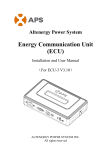
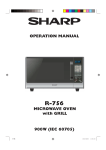
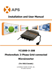
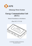
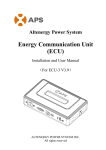
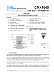
Installation and User Manual YC1000-3 Photovoltaic 3-Phase Grid-connected Microinverter (For Australia/New Zealand) ALTENERGY POWER SYSTEM, INC. All rights reserved Table of Contents 1. IMPORTANT SAFETY INSTRUCTIONS.......................................................................................... 2 Safety Instructions..............................................................................................................................2 Radio interference statement............................................................................................................ 3 Symbols replace words on the equipment, on a display....................................................................3 2. APS Microinverter System Introduction........................................................................................... 4 3. APS Three-phase Microinverter YC1000-3 Introduction.............................................................. 6 4. APS Microinverter System Installation............................................................................................. 7 Additional Installation components from APS.................................................................................. 8 Required Parts and Tools from you................................................................................................... 8 Installation Procedures...................................................................................................................... 8 Step 1 - Installing the AC Branch Circuit AC Isolator.......................................................................................................... 8 Step 2 – Attaching the antenna to the Microinverter.......................................................................................................... 8 Step 3 – Attaching the APS Microinverters to the Racking................................................................................................. 9 Step 4 - Connecting the APS Microinverter AC Cables to the AC bus cable....................................................................... 9 Step 5 –Install a protective end cap at the end of AC bus cable........................................................................................10 Step 6 –Connecting APS Microinverters to the PV Module...............................................................................................10 Step 7- Completing the APS Installation Map.................................................................................................................... 11 5. APS Microinverter System Operating instructions....................................................................... 12 6. Troubleshooting...................................................................................................................................13 Status Indications and Error Reporting.......................................................................................... 13 Troubleshooting a non-operating APS Microinverter.................................................................... 14 7. Replace a Microinverter..................................................................................................................... 15 8. Technical Data...................................................................................................................................... 16 YC1000-3 Technical Specifications..................................................................................................17 9. Wiring Diagram.................................................................................................................................... 18 Three Phase Sample Wiring Diagram............................................................................................. 18 1 Version:1.4 1. IMPORTANT SAFETY INSTRUCTIONS This manual contains important instructions that must be followed during installation and maintenance of the APS Photovoltaic Grid-connected Inverter (Microinverter). To reduce the risk of electrical shock and ensure the safe installation and operation of the APS Microinverter, the following symbols appear throughout this document to indicate dangerous conditions and important safety instructions. SAVE THESE INSTRUCTIONS– This manual contains important instructions for Models YC1000-3 that must be followed during installation and maintenance of the Photovoltaic Grid-connected Inverter. WARNING: This indicates a situation where failure to follow instructions may cause a serious hardware failure or personnel danger if not applied appropriately. Use extreme caution when performing this task. NOTE: This indicates information that is important for optimized microinverter operation. Follow these instructions closely. NOTE: Pollution degree 1:no pollution or only dry, non-conductive pollution occurs. The pollution has no influence. Safety Instructions Only qualified professionals should install and/or replace APS Microinverters. Perform all electrical installations in accordance with local electrical codes. Before installing or using the APS Microinverter, please read all instructions and cautionary markings in the technical documents and on the APS Microinverter system and the PV-array. Be aware that the body of the APS Microinverter is the heat sink and can reach a temperature of 80°C. To reduce risk of burns, do not touch the body of the microinverter. Do NOT disconnect the PV module from the APS Microinverter without first disconnecting the AC power. Do NOT attempt to repair the APS Microinverter. If it fails, contact APS Customer Support to obtain an RMA number and start the replacement process. Damaging or opening the APS Microinverter will void the warranty. Do NOT expose the connection to directed, pressurized liquid (water jets, etc.). Do NOT expose the connection to continuous immersion. Do NOT expose the AC connector to continuous tension (e.g., tension due to pulling or bending the cable near the connection). Use only the connectors and cables provided. Do NOT allow contamination or debris in the connectors. Use the cable and connectors only when all parts are present and intact. Use the terminator to seal the conductor end of the Engage Cable; no other method is allowed. 2 Version:1.4 Radio interference statement RCM/C-TICK Compliance:The equipment can comply with the limits from RCM/C-TICK reqiurement, which are designed to protect against harmful interference in a residential installation. The equipment could radiate radio frequency energy and this might cause harmful interference to radio communications if not following the instructions when installing and using the equipment. But there is no guarantee that interference will not occur in a particular installation. If this equipment causes harmful interference to radio or television reception, the following measures might resolve the issues: A) Relocate the receiving antenna and keep it well away from the equipment B) Consult the dealer or an experienced radio/TV technical for help。 Changes or modifications not expressly approved by the party responsible for compliance may void the user’s authority to operate the equipment. Symbols replace words on the equipment, on a display. Dangerous electrical voltage This device is directly connected to public grid, thus all work to the inverter shall only be carried out by qualified personnel. NOTICE, danger! This device directly connected with electricity generators and public grid. Danger of hot surface The components inside the inverter will release a log of heat during operation, DO NOT touch aluminum housing during operating. An error has occurred Please go to Chapter 10 “Trouble Shooting” to remedy the error. This device SHALL NOT be disposed of in residential waste Please go to Chapter 9 “Recycling and Disposal” for proper treatments. 3 Version:1.4 2. APS Microinverter System Introduction The APS Microinverter is an inverter system for use in utility-interactive applications, comprised of three key elements: Altenergy Power Systems Microinverter Altenergy Power Systems Energy Communication Unit (ECU) Altenergy Power Systems Energy Monitor and Analysis (EMA) web-based monitoring and analysis system This integrated system improves safety; maximizes solar energy harvest; increases system reliability, and simplifies photovoltaic (PV) system design, installation, maintenance, and management. 4 Version:1.4 The APS Microinverters maximize energy production from photovoltaic (PV) arrays. Each PV module is operating at the maximum peak power point, which ensures that the maximum power is exported to the utility grid. When PV modules in the array are affected by shading, soiling, orientation, or mismatch, the APS Microinverter ensures top performance from the array by maximizing the performance of the module within the array. The APS Microinverter system is more reliable than centralized or string inverters. The distributed Microinverter system ensures that no single point of system failure exists across the PV system. APS Microinverters are designed to operate at full power at ambient temperatures of up to 65°C. The inverter housing is designed for outdoor installation and complies with the IP67environmental enclosure rating. PV systems using APS Microinverters are very simple to install. You can install individual PV modules in any combination of module quantity, orientation, type, and power rate. The APS Microinverter system provides smart system performance monitoring and analysis. The APS Energy Communication Unit (ECU) is installed by simply plugging it into any wall outlet and providing an Ethernet or Wi-Fi connection to a broadband router or modem. After installing the ECU, the full network of APS Microinverters automatically reports to the APS Energy Monitor and Analysis (EMA) web server. The EMA software displays performance trends, informs you of abnormal events, and controls system shutdown when it is needed. 5 Version:1.4 3. APS Three-phase Microinverter YC1000-3 Introduction The APS YC1000-3Microinvertersconnect with the Three-phase grid, and operate with most 60 and 72 cell PV modules. For more information, please see the section 8 Technical Date of this manual. Model Number AC grid PV Module Module Connector YC1000-3 230V/400V 60,72Cell MC-4 Type or Customize The following figure shows the APSYC1000-3Microinverterschematic: 6 Version:1.4 4. APS Microinverter System Installation A PV system using APS Microinverters is simple to install. Each microinverter easily mounts on the PV racking, directly beneath each PV module. Low voltage DC wires connect from the PV module directly to the microinverter, eliminating the risk of high DC voltage. Installation shall comply with local regulations and technical rules. Special Statement:An AC GFCI device should not be used to protect the dedicated circuit to the APS Microinverter even though it is an outside circuit. None of the small GFCI devices (5mA-30mA) are designed for back feeding and will be damaged if back feed. In a similar manner, AC AFCIs have not been evaluated for back feeding and may be damaged if back feed with the output of a PV inverter。 WARNING: Perform all electrical installations in accordance with local electrical codes. WARNING: Be aware that only qualified professionals should install and/or replace APS Microinverters. WARNING: Before installing or using an APS Microinverter, please read all instructions and warnings in the technical documents and on the APS Microinverter system itself as well as on the PV array. WARNING: Be aware that installation of this equipment includes the risk of electric shock. WARNING: Do not touch any live parts in the system, including the PV array, when the system has been connected to the electrical grid. WARNING: Electrical Installation & Maintenance shall be conducted by licensed electrician and shall comply with Australia National Wiring Rules. 7 Version:1.4 Additional Installation components from APS Protective end cap (sold separately) sealling caps (sold separately) Required Parts and Tools from you In addition to your PV array and its associated hardware, you will need the following items: An AC connection AC isolator Mounting hardware suitable for module racking Sockets and wrenches for mounting hardware Continuous grounding conductor and grounding washers A Phillips screwdriver A torque wrench Installation Procedures WARNING: Do NOT connect APS Microinverters to the utility grid or energize the AC circuit until you have completed all of the installation procedures as described in the following sections. Step 1 - Installing the AC Branch Circuit AC Isolator a. Install an appropriate AC isolator at a suitable location on the PV racking system (typically at the end of a branch of modules). b. Connect the open wire end of the AC bus cable into the AC isolator using an appropriate gland or strain relief fitting. c. Wire the conductors: L1- RED; L2 - BLACK; L3 - ORANGE;N - WHITE; PE – GREEN.. d. Connect the AC branch circuit AC isolator to the point of utility interconnection. Step 2 – Attaching the antenna to the Microinverter 8 Version:1.4 Step 3 – Attaching the APS Microinverters to the Racking a. Mark the location of the microinverter on the rack, with respect to the PV module AC isolator or any other obstructions. b. Mount one microinverter at each of these locations using hardware recommended by your module racking vendor. WARNING: Prior to installing any of the microinverters, verify that the utility voltage at the point of common connection matches the voltage rating on microinverter label. WARNING: Do not mount the microinverter in a location that allows exposure to direct sunlight. Allow a minimum of 1.5 centimeters between the top of the roof and the bottom of the microinverter. Step 4 - Connecting the APS Microinverter AC Cables to the AC bus cable. NOTE: Cover all unused T connectors with sealling caps to protect the T connectors. 9 Version:1.4 Step 5 –Install a protective end cap at the end of AC bus cable. a.Wirestripping c. Insert five wires into five cable clamps b. Insert the cable endinto the gasket clamp. d. Rotate the nut with 2.5N·m until the Nut Gaske Seal latching mechanism meets the base. Body Clamp Step 6 –Connecting APS Microinverters to the PV Module Photovoltaic panels and microinverter DC input cable connection according to demand. WARNING: Ensure that all AC and DC wiring is correct. Ensure that none of the AC and DC wires are pinched or damaged. Ensure that all AC isolators are properly closed. 10 Version:1.4 ` Step 7- Completing the APS Installation Map You need to fill-in APS Warranty Cards, which provide system information and installation map. Feel free to provide your own layout if a larger or more intricate installation map is required. a. Each APS Microinverter has removable serial number labels. Peel a label off, and affix it to the respective location on the APS installation map. b. Fill the warranty cards and email to APS at [email protected] c. APS will setup the EMA account and email you information, and then you can use the EMA website to view detailed performance of your PV system. NOTE: 1. Step 1 ~ 7 can change sequence for convenience of installation. 2. Warranty card is located in Appendix last page of this manual. 11 Version:1.4 ` 5. APS Microinverter System Operating instructions To operate the APS Microinverter PV system: 1. Turn ON the AC circuit breaker on each microinverter AC branch circuit. 2. Turn ON the main utility-grid AC circuit breaker. Your system will start producing power after a five-minute waiting time. NOTE: once DC power is applied, the Status LED of each microinverter will blink green three times to indicate normal start-up operation. 3. The APS Microinverters will start to send performance data over Wired or wireless to the ECU. The time required for all the microinverters in the system to report to the ECU will vary with the number of microinverters in the system. You can verify proper operation of the APS Microinverters via the ECU. See the ECU Installation and Operation Manual for more information. 12 Version:1.4 ` 6. Troubleshooting Qualified personnel can use the following troubleshooting steps if the PV system does not operate correctly. Status Indications and Error Reporting Startup LED When DC power is first applied to the microinverter: Three short green blinks when DC power is first applied to the microinverter indicate successful microinverter startup Operating LED Flashing Slow Green (10s gap) - Producing power and communicating with ECU Flashing Fast Green (2s gap) – Producing power and not communicating with ECU Flashing Red – Not producing power Other Faults All other faults are reported to the ECU. Refer to the ECU Installation and Operation Manual for a list of additional faults and troubleshooting procedures. WARNING: Be aware that only qualified personnel should troubleshoot the APS Microinverter. WARNING: Never disconnect the DC wire connectors under load. Ensure that no current is flowing in the DC wires prior to disconnecting. An opaque covering may be used to cover the module prior to disconnecting the module. WARNING: Always disconnect AC power before disconnecting the PV module wires from the APS Microinverter. The AC connector of the first microinverter in a branch circuit is suitable as a disconnecting means once the AC branch circuit breaker in the load center has been opened. WARNING: The APS Microinverteris powered by PV module DC power. Make sure you disconnect and reconnect the DC connections to watch for the three short LED flashes. 13 Version:1.4 ` Troubleshooting a non-operating APS Microinverter To troubleshoot a non-operating APS Microinverter, follow the steps below in order: 1. Verify the utility voltage and frequency are within ranges shown in the in section 8 Technical Data of this manual. 2. Check the connection to the utility grid. Verify utility power is present at the inverter in question by removing AC, then DC power. Never disconnect the DC wires while the microinverter is producing power. Re-connect the DC module connectors and watch for three short LED flashes. 3. Check the AC branch circuit interconnection between all the microinverters. Verify each inverter is energized by the utility grid as described in the previous step. 4. Make sure that any AC breaker are functioning properly and are closed. 5. Check the DC connections between the microinverter and the PV module. 6. Verify the PV module DC voltage is within the allowable range shown in the Section 8 Technical Data of this manual. 7. If the problem persists, please call APS Energy customer support. WARNING: Do not attempt to repair the APS Microinverter. If troubleshooting methods fail, please return the microinverter to your distributor for replacement. 14 Version:1.4 ` 7. Replace a Microinverter Follow the procedure to replace a failed APS Microinverter. 1. Remove the APS Microinverter from the PV Module, in the order shown below: 1) Disconnect the AC by opening the branch circuit breaker. 2) Cover the module with an opaque cover. 3) Disconnect the first AC connector in the branch circuit. 4) Disconnect the PV module DC wire connectors from the microinverter. 5) Remove the microinverter from the PV array racking. 2. Install a replacement microinverter to the rack. 3. Connect the AC cable of the replacement microinverter and the neighboring microinverters to complete the branch circuit connections. 4. Close the branch circuit breaker, and verify operation of the replacement microinverter. 15 Version:1.4 ` 8. Technical Data WARNING: Be sure to verify the voltage and current specifications of your PV module match with those of the microinverter. WARNING: You must match the DC operating voltage range of the PV module with the allowable input voltage range of the APS Microinverter. WARNING: The maximum open circuit voltage of the PV module must not exceed the specified maximum input voltage of the APS Microinverter. 16 Version:1.4 YC1000-3 Technical Specifications Type YC1000-3 Input Data (DC) Recommended PV Module Power (STC)Range MPPT Voltage Range Operation Voltage Range Maximum Input Voltage Startup Voltage Maximum Input Current Output Data (AC) Maximum Output Power 3-Phase Grid Type Maximum Output Current Nominal Output Voltage Default Output Voltage Range Extended Output Voltage Range Nominal Output Frequency Default Output Frequency Range Extended Output Frequency Range Power Factor Total Harmonic Distortion Efficiency Peak efficiency CEC Weighted efficiency Nominal MPPT efficiency Night Power Consumption Mechanical Data Operating Ambient temperature range Operating Internal temperature range Storage Temperature Range Dimensions (W * H * D) Weight Enclosure rating Cooling 180W-310W 16V-55V 16V-55V 60V 22V 14.8A×4 900W 230V/400V 1.30A×3 230V×3 200V-270V1 149V-278V 50Hz 47.5Hz-50.5Hz1 45.1Hz-54.9Hz >0.99 <3% 95% 94 % 99.9% 300mW -40 oCto +65 oC -40 oCto +85 oC -40 oCto +85 oC 259mm * 242mm *36mm 3.8kg IP67 Natural Convection All data at this technical Specifications has been tested under <2000m Maximum Altitude Rating Features Communication Grid Connection Compliance Safety Class Compliance Power line, Zigbee AS 4777.2/AS 4777.3 AS3100 1 Programmable through ECU in field to meet customer need. The specifications are subject to change without notice. 17 Version:1.4 9. Wiring Diagram Three Phase Sample Wiring Diagram 18 Version:1.4 ALTENERGY POWER SYSTEM Inc. 1 Yatai Road, Jiaxing, PR China 314050 Phone:+86-21-68889199 Fax: +86-21-33928752 www.APSMicroinverter.com APS Microinverter&Energy Communication Unit Warranty Card The APSInstallation Map is a diagram of the physicallocation of each microinverter in your PV installation. Each APS Microinverter has a removable serial number label locatedon the mounting plate. Peel the label andaffix it to the respective location on theAPSinstallation map. Installation Map Template 1 2 3 4 5 6 7 8 9 10 11 12 13 14 A B C To register your APS Microinverter, please mail this warranty registration card to: [email protected] 20 Version:1.4