1
Chapter 3
Calibrations and Overheads
In this section we discuss the overheads incurred and the minimum calibration requirements for
HERMES data.
3.1
Detector Settings
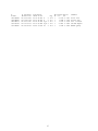
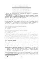
HERMES CCDs can be readout using SLOW, NORMAL and FAST readout modes with 1,
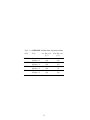
2 or 4 amplifiers. Tables 3.1 show the gain, readout noise, and readout times for the various
readout modes using a single top left amplifier. The values for other individual amplifiers are
very similar to those in Table 3.1. A faster NON-ASTRO readout mode is also possible but
not supported for science observations due to known spurious effects. This mode is only made
available for engineering tests.
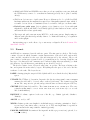
Using the two Left amplifiers or two Right amplifiers readout the detector in the spatial
direction where fibres 1 - 200 are readout with the bottom amplifier and fibres 201 - 400 are
readout with the top amplifier. This avoids splitting the data in the spectral direction and is
the default amplifier setting.
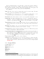
Using two Top amplifiers or two Bottom amplifiers readout the detector in the spectral di-
Table 3.1: HERMES Readout Modes
CCD
BLUE
GREEN
RED
IR
Mode
Fast
Normal
Slow
Fast
Normal
Slow
Fast
Normal
Slow
Fast
Normal
Slow
Readout time
(sec)
144
282
420
144
282
420
144
282
420
144
282
420
25
Gain
(e− /ADU)
2.6
1.8
1.2
3.0
2.0
1.4
3.1
1.9
1.4
2.7
1.5
0.7
Read Noise
(e− )
4.1
3.2
2.9
4.4
3.1
2.6
4.9
3.1
2.9
4.4
3.5
3.0