1
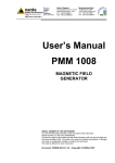
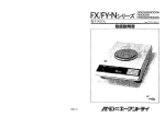
NARDA Safety Test Solutions S.r.l. Socio Unico Sales & Support: Via Leonardo da Vinci, 21/23 20090 Segrate (MI) - ITALY Tel.: +39 02 2699871 Fax: +39 02 26998700 Manufacturing Plant: Via Benessea, 29/B 17035 Cisano sul Neva (SV) Tel.: +39 0182 58641 Fax: +39 0182 586400 http://www.narda-sts.it User’s Manual PMM 6000N WIDEBAND RF POWER AMPLIFIER 9 kHz - 230 MHz / 10 Watts SERIAL NUMBER OF THE INSTRUMENT You can find the Series Number on the rear panel of the instrument. Series Number is in the form: 0000X00000. The first four digits and the letter are the Series Number prefix, the last five digits are the Series Number suffix. The prefix is the same for identical instruments, it changes only when a configuration change is made to the instrument. The suffix is different for each instrument. Document 6000NEN-90404 – Copyright © NARDA 2007 NOTE: If the instrument is used in any other way than as described in this Users Manual, it may become unsafe Before using this product, the related documentation must be read with great care and fully understood to familiarize with all the safety prescriptions. To ensure the correct use and the maximum safety level, the User shall know all the instructions and recommendations contained in this document. This product is a Safety Class I and Installation Category II instrument according to IEC classification and has been designed to meet the requirements of EN61010-1 (Safety Requirements for Electrical Equipment for Measurement, Control and Laboratory Use). This product has a Pollution Degree II normally only non-conductive pollution occurs. Occasionally, however, a temporary conductivity caused by condensation must be expected. The information contained in this document is subject to change without notice. KEY TO THE ELECTRIC AND SAFETY SYMBOLS: You now own a high-quality instrument that will give you many years of reliable service. Nevertheless, even this product will eventually become obsolete. When that time comes, please remember that electronic equipment must be disposed of in accordance with local regulations. This product conforms to the WEEE Directive of the European Union (2002/96/EC) and belongs to Category 9 (Monitoring and Control Instruments). You can return the instrument to us free of charge for proper environment friendly disposal. You can obtain further information from your local Narda Sales Partner or by visiting our website at www.narda-sts.it . Warning, danger of electric shock Earth Read carefully the Operating Manual and its instructions, pay attention to the safety symbols. Unit Earth Connection Earth Protection Equipotential KEY TO THE SYMBOLS USED IN THIS DOCUMENT: The DANGER sign draws attention to a potential risk to a person’s DANGER safety. All the precautions must be fully understood and applied before proceeding. WARNING The WARNING sign draws attention to a potential risk of damage to the apparatus or loss of data. All the precautions must be fully understood and applied before proceeding. CAUTION The CAUTION sign draws attention against unsafe practices for the apparatus functionality. NOTE: II The NOTE draw attention to important information. Note and symbols Contents General safety considerations and instructions......... EC Conformity Certificate………………………………... Page V VI 1 General information 1.1 Documentation.....................................…...............… 1.2 Introduction ……………….....................................…. 1.3 Instrument items..............................…................…… 1.4 Optional accessories.....…...........………………...…. 1.5 Main specifications............................…...............….. 1.6 Typical Performances…………………………………. 1.7 Front panel.............……………........….......….....…… 1.8 Rear panel………….........................….......….....…… Page 1-1 1-1 1-1 1-1 1-2 1-3 1-6 1-6 2 Installation 2.1 Introduction.......................................…..................… 2.2 Initial inspection.................................….................… 2.3 Packing and unpacking....................…..................… 2.4 Preparation for use.........................….....................… 2.5 Installation check list......................….....................… 2.6 Line voltage selection.....................….....................… 2.7 Fuse selection..................................…...................... 2.8 Power cable........................................….................... 2.9 Environment.....................................…...................... 2.10 Return for service..........................…...................…. 2.11 Equipment cleaning.......................…....................… 2.12 Hardware installation...................….....................…. Page 2-1 2-1 2-1 2-1 2-1 2-1 2-2 2-2 2-2 2-2 2-2 2-2 3 Operating Instruction 3.1 Cooling.................................................….................. 3.2 Damage precautions.............................…................. 3.3 Connection to power source................….................. 3.4 Front panel indicators..........................….................. 3.5 Placing equipment in service.....................…............ Page 3-1 3-1 3-1 3-1 3-1 Contents III Figures Figure 1-1 1-2 Page Front Panel.......................................….....…... Rear Panel........................................…........... 1-6 1-6 Tables Table 1-1 Page Technical Specifications...................…........... IV Contents 1-2 SAFETY RECOMMENDATIONS AND INSTRUCTIONS This product has been designed, produced and tested in Italy, and it left the factory in conditions fully complying with the current safety standards. To maintain it in safe conditions and ensure correct use, these general instructions must be fully understood and applied before the product is used. • When the device must be connected permanently, first provide effective grounding; • If the device must be connected to other equipment or accessories, make sure they are all safely grounded; • In case of devices permanently connected to the power supply, and lacking any fuses or other devices of mains protection, the power line must be equipped with adequate protection commensurate to the consumption of all the devices connected to it; • In case of connection of the device to the power mains, make sure before connection that the voltage selected on the voltage switch and the fuses are adequate for the voltage of the actual mains; • Devices in Safety Class I, equipped with connection to the power mains by means of cord and plug, can only be plugged into a socket equipped with a ground wire; • Any interruption or loosening of the ground wire or of a connecting power cable, inside or outside the device, will cause a potential risk for the safety of the personnel; • Ground connections must not be interrupted intentionally; • To prevent the possible danger of electrocution, do not remove any covers, panels or guards installed on the device, and refer only to NARDA Service Centers if maintenance should be necessary; • To maintain adequate protection from fire hazards, replace fuses only with others of the same type and rating; • Follow the safety regulations and any additional instructions in this manual to prevent accidents and damages. Safety consideration V EC Conformity Certificate (in accordance with the directives: EMC 89/336/EEC and low voltage 73/23/EEC) This is to certify that the product: PMM 6000N Wideband RF Power Amplifier Produced by: NARDA S.r.l. Safety Test Solution Via Benessea 29/B 17035 Cisano sul Neva (SV) - ITALY complies with the following European Standards: Safety: CEI EN 61010-1 (2001) EMC: EN 61326-1 (2007) This product complies with the requirements of the Low Voltage Directive 2006/95/CE and the EMC Directive 2004/108/CE. The PMM 6000N Wideband RF Power Amplifier MUST BE USED IN THE CONFINES OF A SHIELDED ROOM, in order to comply with the requirements of the referenced EMC Directive. NARDA S.r.l. VI EC Conformity 1 - General Information 1.1 Documentation Enclosed with this manual are: • a service questionnaire to send back to NARDA in case of equipment service is needed • an accessories check list to verify all accessories enclosed in the packaging. 1.2 Introduction PMM 6000N is a wideband RF power amplifier covering a 9 kHz ÷ 230 MHz frequency range with output power level of 10 Watts into a 50 Ohm load. In the 150 kHz ÷ 80 MHz frequency range the amplifier performs a output power level of 15 Watts. The amplifier employs a fully MOSFET technology and is biased for Class A operation assuring good performance, reliability and high tolerance to load mismatch conditions. With an overall gain of 40 dB, PMM 6000N has been designed with frequency range and performance according to Basic immunity Standard EN 61000-4-6 (IEC 1000-4-6). It is ideally suited for wideband power sweeping and is compatible with most RF signal generators capable of 1mW of signal output. A front panel-mounted RF power meter facilitates monitoring the amplifier output signal in Watts into 50 Ohm loads. 1.3 Instrument items PMM 6000N includes the following items: • 10 Watts power amplifier from 9 kHz up to 230 MHz; • Power cable; • Operating manual; • BNC-BNC cable; • N-BNC adapter 1.4 Optional accessories The following accessories may be ordered as options: • PMM 3000 RF- signal generator; • 150-to-15 Ohm adapters; • 6 dB, 50 Ohm fixed attenuator; • Coupling/Decoupling Networks; • EM current injection clamp • Selective Voltmeter • Current Probe Document 6000NEN-90404 - © NARDA 2007 General Information 1-1 1.5 Main specifications Table 1-1 lists the PMM 6000N performance specifications. The following conditions apply to the specification: • The PMM 6000N needs at least 5 minutes warm-up before operate; • The ambient temperature shall be 10° to 40° C. TABLE 1-1 Technical specifications Frequency Range: 9 kHz ÷ 230 MHz Power output: 10 Watts CW into 50 Ohm (15 Watts CW into 50 Ohm in the 150 kHz ÷ 80 MHz range) Power Gain: 40 dB Gain flatness: + 1 dB - 1,5 dB Mode of operation: Class A linear, MOS-FET Drive level: 0 dBm (1 mW) for 10 Watts output Input impedance 50 Ohm nominal Input return loss: Output impedance: Harmonic distortion: Spurious: < - 20 dB 50 Ohm nominal < - 20 dBc < - 70 dBc typ Connectors: BNC input, N output Cooling (internal): Power supply: forced air cooling 85 ÷ 264 VAC or 120 ÷ 370 VDC pre-wired, 47 ÷ 440 Hz, 60 W Dimensions (W x H x L): 257 mm x 110 mm x 315 mm Weight: 3.5 Kg Rack mounting: RFI proof aluminum enclosure Main fuse: 1,6 AT fuse Protection: Temperature / Current Metering: 1-2 0 ÷ 20 W full scale into 50 Ohm General Information 1.6 Typical Performances Typical Gain at Nominal Power [dB] [dB] 50 48 46 44 42 40 38 36 34 32 30 0.001 0.01 0.1 1 10 100 1000 100 1000 [MHz] Typical Gain at Nominal Power/2 [dB] [dB] 50 48 46 44 42 40 38 36 34 32 30 0.001 0.01 0.1 1 10 [MHz] General Information 1-3 Power output at 1dBc [W] [W] 20.0 18.0 16.0 14.0 12.0 10.0 8.0 6.0 4.0 2.0 0.0 0.001 0.01 0.1 1 10 100 1000 100 1000 [MHz] Compression at Nominal Power [dBc] [dB] 1 0.9 0.8 0.7 0.6 0.5 0.4 0.3 0.2 0.1 0 0.001 0.01 0.1 1 [MHz] 1-4 General Information 10 2nd Harmonic at Pn [dBc] 3rd Harmonic at Pn [dBc] [dBc] 0 -5 -10 -15 -20 -25 -30 -35 -40 -45 0.001 0.01 0.1 1 10 100 1000 [MHz] General Information 1-5 1.7 Front panel Fig 1-1: Front Panel Legend: 1 - Input BNC Connector 2 - Output N Connector 3 - Power Meter 4 - Power On Light 5 - Alarm Light 1.8 Rear panel Fig 1-2: Rear Panel Legend: 1 - Mains power switch 2 - Fuse receptacle 3 - Mains power connector 4 - Equipment serial number 5 - Vent fan 1-6 General Information 2 - Installation 2.1 Introduction This section provides the information needed to install your PMM 6000N. Included is information pertinent to initial inspection, power requirements, line voltage and fuse selection, power cables, interconnection, environment, instrument mounting, cleaning, storage and shipment. 2.2 Initial inspection A WARNING 2.3 Packing and Unpacking To avoid hazardous electrical shock, do not turn on the instrument when there are signs of shipping damage to any portion of it. Inspect the shipping container for damage. If the shipping container or cushion material is damaged, it should be kept until the contents of the shipment have been checked for completeness and the instrument has been checked mechanically and electrically. Verify the accessories availability in the shipping referring to the accessories check list enclosed with the Users Manual. Notify any damage to the carrier personnel as well as the NARDA Representative. 2.4 Preparation for use A WARNING This is a Safety Class I equipment, it is provided with a protective earth terminal. An uninterruptible safety earth ground must be provided from the main power source to the product input wiring terminals through the power cable (or supplied power cable set). Verify the safety earth ground functionality before operation. 2.5 Installation Check list Before operation the following steps shall be taken: • Check the line voltage to ensure the compatibility with the equipment settings. • Verify that the fuse rating is appropriate for the line voltage used. Before plugging PMM 6000N into the main supply line ensure that the line voltage is in the range specified, and that the appropriate fuse have been selected. 2.6 Line voltage selection The line voltage will be prewired at NARDA factory. The internal power supply can accept the voltages specified in "Main specifications" section. Document 6000NEN-90404 - © NARDA 2007 Installation 2-1 Line Voltage 85 ÷ 264 V 2.7 Fuse selection A Fuse Rating 1,6 AT Type Slow Action Before connecting this instrument, ensure that an uninterruptible safety earth ground is provided from the main power source to the product protective earth connection. If this instrument is to be connected to other equipment or accessories, prior to energizing either unit verify that a common ground exists between them. Any interruption or loosening of the protective earth ground conductor, either inside or outside the unit or in an extension cable will cause a potential shock hazard that could result in personal injury. WARNING 2.8 Power cable This instrument is equipped with a three wires power cable. When connected to an appropriate AC power receptacle, this cable grounds the instrument chassis. 2.9 Environment The operating environment is specified to be within the following limitations: +10° to +40° C • Temperature < 90% relative • Humidity 4000 meters • Altitude The instrument should be stored in a clean, dry environment The storage and shipping environment is specified to be within the following limitations: -40° to + 50° C • Temperature < 95% relative • Humidity 15000 meters • Altitude 2.10 Return for service If the instrument should be returned to NARDA for service, please complete the service questionnaire enclosed with the Users Manual and attach it to the instrument. To minimize the repair time, be as specific as possible when describing the failure. If the failure only occurs under certain conditions, explain how to duplicate the failure. If possible, reuse of the original packaging to ship the equipment is preferable. In case other package should be used, ensure to wrap the instrument in heavy paper or plastic. Use a strong shipping container and use enough shock absorbing material around all sides of the equipment to provide a firm cushion and prevent movement in the container. To prevent damage during shipment in particular protect the front panel. Seal the shipping container securely. Mark the shipping container FRAGILE to encourage careful handling. 2.11 Equipment cleaning Use a clean, dry, non abrasive cloth for equipment fan opening cleaning. To clean the equipment do not use any solvent, thinner, turpentine, acid, acetone or similar matter to avoid damage to external enclosure. 2.12 Hardware Installation 2-2 PMM 6000N is delivered ready to use. Remove the amplifier from his cardboard box and connect power cable to rear panel mains plug. Push the main switch to "ON" position and wait few seconds. Connect an RF generator to input connector. The Amplifier output must be terminated into 50 Ohm. The PMM 6000N needs at least 5 minutes warm-up before operate. Installation 3 - Operating Instruction 3.1 Cooling It is necessary to ensure that the PMM 6000N forced-air cooling system be allowed to operate at maximum efficiency. Cooling depends upon the free flow of cooling air through the bottom and the rear of the unit. Take care to keep these areas free of any objects that could obstruct this free air flow. 3.2 Safety Precautions Input power to the unit should not exceed 0 dBm (1 mW). Although the system has no provisions designed for output VSWR protection, MOSFET's amplifier technology exhibits itself high tolerance to load mismatches To avoid any damage of the amplifier: 1. Don’t exceed a drive level of 0 dBm (1mW) for 10 W output. 2. Ensure a 50 Ohm load is connected to the Amplifier output before operation. 3. Ensure the vent grid be free to allow a correct Amplifier ventilation. 3.3 Connection to Power PMM 6000N operates from 85 to 264 VAC thanks to its internal switching power supply. The AC Voltage input selection is thus not required. The unit Source is connected to the AC power outlet with line cord supplied. 3.4 Front Panel indicators PMM 6000N amplifier has no critical adjustment. Power Indicator: Lights when the amplifier is switched on; Flashing when internal protection is active (current limiter) Alarm Indicator: Lights when internal temperature exceeds 60° C; Panel Meter Indicator: Indicates power output Watts into 50 Ohm load. 3.5 Placing Equipment In It is a good practice to follow the procedure below for placing the amplifier in service: Service - Connect the load to the PMM 6000N Amplifier “OUTPUT” by a N connector and coaxial cable of 50 Ohm impedance. To avoid any RF interference, it is suggested to use only proper shielded cable and high quality RF connectors. - Without signal applied to the input, switch the POWER switch on the rear panel to the ON position. The power light indicator will come on and fans will start. Watch the power meter and increase the signal source until a meter reading is observed. If your load is a 50 Ohm load, you can read the output power directly on the meter scale. The unit is protected against over-temperature by temperature sensing switch in the supply section of the amplifier module. In case of such a condition the alarm indicator on the front panel will come on for the duration of the over temperature condition. - The PMM 3000 or other RF Signal Generator driving the PMM 6000N linear Amplifier should be connected to the BNC “INPUT” connector at the front panel using a 50 Ohm coaxial cable. The nominal drive level to achieve the maximum output power is 0 dBm corresponding to 1mW into 50 Ohm. Document 6000NEN-90404 - © NARDA 2007 Operating Instruction 3-1 This page intentionally left blank 3-2 Operating Instruction NARDA Safety Test Solutions S.r.l. Socio Unico Sales & Support: Via Leonardo da Vinci, 21/23 20090 Segrate (MI) - ITALY Tel.: +39 02 2699871 Fax: +39 02 26998700 Manufacturing Plant: Via Benessea, 29/B 17035 Cisano sul Neva (SV) Tel.: +39 0182 58641 Fax: +39 0182 586400 http://www.narda-sts.it Mod. 18-1 Caro cliente grazie per aver acquistato un prodotto NARDA! Sei in possesso di uno strumento che per molti anni ti garantirà un’alta qualità di servizio. NARDA riconosce l'importanza del Cliente come ragione di esistenza; ciascun commento e suggerimento, sottoposto all'attenzione della nostra organizzazione, è tenuto in grande considerazione. La nostra qualità è alla ricerca del miglioramento continuo. Se uno dei Suoi strumenti NARDA necessita di riparazione o calibrazione, può aiutarci a servirla più efficacemente compilando questa scheda e accludendola all’apparecchio. Tuttavia, anche questo prodotto diventerà obsoleto. In questo caso, ti ricordiamo che lo smaltimento dell'apparecchiatura deve essere fatto in conformità con i regolamenti locali. Questo prodotto è conforme alle direttive WEEE dell’Unione Europea (2002/96/EC) ed appartiene alla categoria 9 (strumenti di controllo). Lo smaltimento, in un ambiente adeguato, può avvenire anche attraverso la restituzione del prodotto alla NARDA senza sostenere alcuna spesa. Può ottenere ulteriori informazioni contattando i venditori NARDA o visitando il nostro sito Web www.narda-sts.it. Dear Customer thank you for purchasing a NARDA product! You now own a high-quality instrument that will give you many years of reliable service. NARDA recognizes the importance of the Customer as reason of existence; in this view, any comment and suggestion you would like to submit to the attention of our service organization is kept in great consideration. Moreover, we are continuously improving our quality, but we know this is a never ending process. We would be glad if our present efforts are pleasing you. Should one of your pieces of NARDA equipment need servicing you can help us serve you more effectively filling out this card and enclosing it with the product. Nevertheless, even this product will eventually become obsolete. When that time comes, please remember that electronic equipment must be disposed of in accordance with local regulations. This product conforms to the WEEE Directive of the European Union (2002/96/EC) and belongs to Category 9 (Monitoring and Control Instruments). You can return the instrument to us free of charge for proper environment friendly disposal. You can obtain further information from your local NARDA Sales Partner or by visiting our website at www.narda-sts.it. 5 Servizio richiesto: 5 Service needed: Solo taratura Calibration only Riparazione Repair Riparazione & Taratura Repair & Calibration Taratura SIT Certified Calibration Altro: Other: Ditta: Company: Indirizzo: Address: Persona da contattare: Technical contact person: Telefono: Phone n. Modello: Equipment model: Numero di serie: Serial n. 5 Accessori ritornati con l’apparecchiatura: Nessuno Cavo(i) Cavo di alimentazione 5 Accessories returned with unit: None Cable(s) Power cable Altro: Other: 5 Sintomi o problemi osservati: 5 Observed symptoms / problems: 5 Guasto: Fisso Intermittente 5 Failure: Continuous Intermittent Sensibile a : Freddo Sensitive to: Cold Caldo Heat Descrizione del guasto/condizioni di funzionamento: Failure symptoms/special control settings description: Se l’unità è parte di un sistema descriverne la configurazione: If unit is part of system please list other interconnected equipment and system set up: Vibrazioni Altro Vibration Other Suggerimenti / Commenti / Note: Suggestions / Comments / Note: