1
STMicroelectronics
OS21 for ST40
User manual
7358673 Rev O
November 2009
www.st.com
BLANK
User manual
OS21 for ST40
Introduction
The API defined in the OS21 User manual (ADCS 7358306) encapsulates the generic
facilities offered by OS21 on all target platforms. However, each processor implements
certain features in different ways, and some processors offer facilities worthy of their own
specific API. ST40 specific features are documented in this manual.
All ST40 specific APIs can be accessed by a single #include:
#include <os21/st40.h>
This include file is automatically included from <os21.h> when __sh__ is defined. The
SH4 GCC compiler always defines __sh__; therefore #include <os21.h> is normally
all that is necessary to include both the generic OS21 API and the ST40 specific API.
ST40 specifics
Default system stack size on ST40
If no size is specified for the system stack when kernel_initialize() is called, OS21
assumes a default stack size of 32 Kbytes.
Note:
The debug kernel always checks for a minimum stack size of 16 Kbytes for OS21.
November 2009
7358673 Rev O
1/23
www.st.com
Contents
OS21, ST40
Contents
Introduction . . . . . . . . . . . . . . . . . . . . . . . . . . . . . . . . . . . . . . . . . . . . . . . . . . . . . . . . . 1
ST40 specifics. . . . . . . . . . . . . . . . . . . . . . . . . . . . . . . . . . . . . . . . . . . . . . . . . . . . . 1
Preface . . . . . . . . . . . . . . . . . . . . . . . . . . . . . . . . . . . . . . . . . . . . . . . . . . . . . . . . . . . . . 4
Document identification and control . . . . . . . . . . . . . . . . . . . . . . . . . . . . . . . . . . . . 4
Conventions used in this guide . . . . . . . . . . . . . . . . . . . . . . . . . . . . . . . . . . . . . . . . 4
1
2
Timers . . . . . . . . . . . . . . . . . . . . . . . . . . . . . . . . . . . . . . . . . . . . . . . . . . . . . 5
1.1
Timers overview . . . . . . . . . . . . . . . . . . . . . . . . . . . . . . . . . . . . . . . . . . . . . 5
1.2
Input clock frequency . . . . . . . . . . . . . . . . . . . . . . . . . . . . . . . . . . . . . . . . . 5
1.3
OS21 tick duration . . . . . . . . . . . . . . . . . . . . . . . . . . . . . . . . . . . . . . . . . . . 5
1.4
ST40 timer assignments . . . . . . . . . . . . . . . . . . . . . . . . . . . . . . . . . . . . . . . 5
Floating point support . . . . . . . . . . . . . . . . . . . . . . . . . . . . . . . . . . . . . . . 7
2.1
3
Register context . . . . . . . . . . . . . . . . . . . . . . . . . . . . . . . . . . . . . . . . . . . . 8
3.1
4
5
2/23
Registers overview . . . . . . . . . . . . . . . . . . . . . . . . . . . . . . . . . . . . . . . . . . . 8
Resets . . . . . . . . . . . . . . . . . . . . . . . . . . . . . . . . . . . . . . . . . . . . . . . . . . . . . 9
4.1
Resets overview . . . . . . . . . . . . . . . . . . . . . . . . . . . . . . . . . . . . . . . . . . . . . 9
4.2
Reset API summary . . . . . . . . . . . . . . . . . . . . . . . . . . . . . . . . . . . . . . . . . . 9
4.3
List of functions . . . . . . . . . . . . . . . . . . . . . . . . . . . . . . . . . . . . . . . . . . . . 10
Constructors and destructors . . . . . . . . . . . . . . . . . . . . . . . . . . . . . . . . 11
5.1
6
Floating point overview . . . . . . . . . . . . . . . . . . . . . . . . . . . . . . . . . . . . . . . . 7
Multiple constructors and destructors . . . . . . . . . . . . . . . . . . . . . . . . . . . 11
Board support package . . . . . . . . . . . . . . . . . . . . . . . . . . . . . . . . . . . . . 12
6.1
Board support package overview . . . . . . . . . . . . . . . . . . . . . . . . . . . . . . . 12
6.2
BSP interrupt system description . . . . . . . . . . . . . . . . . . . . . . . . . . . . . . . 12
6.2.1
Interrupt names . . . . . . . . . . . . . . . . . . . . . . . . . . . . . . . . . . . . . . . . . . . 12
6.2.2
Interrupt groups . . . . . . . . . . . . . . . . . . . . . . . . . . . . . . . . . . . . . . . . . . . 13
7358673
OS21, ST40
7
Contents
6.2.3
Interrupt tables . . . . . . . . . . . . . . . . . . . . . . . . . . . . . . . . . . . . . . . . . . . . 13
6.2.4
INTC base address . . . . . . . . . . . . . . . . . . . . . . . . . . . . . . . . . . . . . . . . 18
6.2.5
INTC2 base address . . . . . . . . . . . . . . . . . . . . . . . . . . . . . . . . . . . . . . . 18
6.2.6
ILC base address . . . . . . . . . . . . . . . . . . . . . . . . . . . . . . . . . . . . . . . . . . 18
6.2.7
Interrupt system initialization flags . . . . . . . . . . . . . . . . . . . . . . . . . . . . . 18
Revision history . . . . . . . . . . . . . . . . . . . . . . . . . . . . . . . . . . . . . . . . . . . 20
7358673
3/23
Preface
OS21, ST40
Preface
Document identification and control
Each book carries a unique identifier of the form:
ADCS nnnnnnnx
where nnnnnnn is the document number, and x is the revision.
Whenever making comments on a document, the complete identification ADCS nnnnnnnx
should be quoted.
Conventions used in this guide
General notation
The notation in this document uses the following conventions:
●
sample code, keyboard input and file names,
●
variables and code variables,
●
code comments,
●
screens, windows and dialog boxes,
●
instructions.
Hardware notation
The following conventions are used for hardware notation:
●
REGISTER NAMES and FIELD NAMES,
●
PIN NAMES and SIGNAL NAMES.
Software notation
Syntax definitions are presented in a modified Backus-Naur Form (BNF). Briefly:
4/23
1.
Terminal strings of the language, that is, strings not built up by rules of the language,
are printed in teletype font. For example, void.
2.
Nonterminal strings of the language, that is, strings built up by rules of the language,
are printed in italic teletype font. For example, name.
3.
If a nonterminal string of the language starts with a nonitalicized part, it is equivalent to
the same nonterminal string without that nonitalicized part. For example,
vspace-name.
4.
Each phrase definition is built up using a double colon and an equals sign to separate
the two sides (‘::=’).
5.
Alternatives are separated by vertical bars (‘|’).
6.
Optional sequences are enclosed in square brackets (‘[’ and ‘]’).
7.
Items which may be repeated appear in braces (‘{’ and ‘}’).
7358673
OS21, ST40
Timers
1
Timers
1.1
Timers overview
The ST40 has three independent timer units (TMUs). Each is capable of running as a free
running auto-reload 32-bit counter, with interrupt on underflow. Each can be programmed to
count either the RTC (16 kHz) or some fraction of the input clock. The greatest accuracy is
obtained by counting based on a large fraction of the input clock, and running that clock at a
high frequency.
1.2
Input clock frequency
The precise speed of the input clock is determined by the end user; it is a function of the
board design and boot software. OS21 is not responsible for setting the input speed,
therefore it has to be made aware of what it is.
This is done with the Board Support Package (BSP) using a function called
bsp_timer_input_clock_frequency_hz(). Full details of this function can be found
in the OS21 User manual (ADCS 7358306), chapter 16.
1.3
OS21 tick duration
OS21 establishes the period of one tick when it boots. Based on the input clock frequency it
selects an appropriate divisor to yield a tick which is approximately 10 microseconds.
1.4
ST40 timer assignments
OS21 uses all three ST40 TMU timers, as shown in Table 1.
Table 1.
ST40 timer assignments
Timer name
OS21 usage
TMU0
System timer
TMU1
Timeslice timer
TMU2
Timeout timer
The system timer is left free running and is used by time_now() to return the system time.
On ST40, the system time (osclock_t) is a 64-bit value. OS21 maintains the top 32 bits of
the 64-bit time using an interrupt handler which is called each time the 32-bit timer reaches
zero. The lower 32 bits of the system time are the value in the system timer.
The timeslice timer is programmed to run for the timeslice period before generating an
interrupt and reloading. This is used to drive timeslice events into the task scheduler.
Note:
When profiling (the application is built with the -pg flag), this timer is used for PC sampling
as well as timeslicing. In this case, it is programmed to yield approximately 16384 interrupts
per second. OS21 ensures that the frequency of timeslice events into the scheduler remains
unchanged.
7358673
5/23
Timers
OS21, ST40
The timeout timer is programmed on demand to interrupt when the required number of ticks
has elapsed. When multiple timeouts are requested, OS21 orders which timeout should
occur next, and programs the timeout timer appropriately.
6/23
7358673
OS21, ST40
Floating point support
2
Floating point support
2.1
Floating point overview
The ST40 processor has a highly efficient FPU, but it has a large register state which makes
a significant contribution to the context data which has to be saved and restored by OS21.
GCC normally uses the FPU to optimize operations like integer divide on the ST40. This
behavior can be disabled with the GCC option -m4-nofpu.
By default OS21 preserves the full FPU state of the FPU on context switch. If you only use
the FPU via standard GCC C/C++ code, only bank-0 FPU registers are used. This means
that OS21 is unnecessarily preserving FPU bank-1 registers. Building the OS21 kernel with
the option -DCONF_FPU_SINGLE_BANK makes a kernel which only saves bank-0 FPU
registers. This results in correspondingly faster context switches, at the expense of not being
able to use FPU bank-1 registers. This should not be a problem unless you are using
custom written FPU code or libraries.
Building the OS21 kernel with the option -DCONF_NO_FPU makes a kernel which does not
perform any FPU saves or restore on context switch, and hence provides the fastest
possible context switches. When using the -DCONF_NO_FPU option both the kernel and all
application code must be compiled with the -m4-nofpu option.
Note:
The version of OS21 which is linked in when the -mruntime=os21 and -m4-nofpu
options are given has precisely this behavior.
7358673
7/23
Register context
3
Register context
3.1
Registers overview
OS21, ST40
The following registers are saved as part of each task’s context:
●
R0 to R7 (bank 0 registers)
●
R8 to R15
●
SR
●
GBR
●
MACL / MACH
●
PR
●
PC
●
FPR0_BANK0 to FPR15_BANK0
●
FPR0_BANK1 to FPR15_BANK1
●
FPSCR
●
FPUL
The following registers are not saved, since they form part of the global context for the
system:
8/23
●
VBR
●
DBR
7358673
OS21, ST40
Resets
4
Resets
4.1
Resets overview
A reset can occur because of a power on, or because of a manual reset. Manual resets are
typically due to programming errors. Examples include the watchdog timer expiring, or a
program requested manual reset.
OS21 does not provide a mechanism for passing more specific data across resets. This is a
board design issue, for instance, data could be placed in NVRAM to signal the precise
reason for a requested reset.
OS21 provides an API for requesting the CPU to be reset, and also for determining the
cause of the last reset (power-on reset or manual reset).
4.2
Reset API summary
Table 2 and Table 3 provide an overview of the reset API. The reset API is obtained by
including the header file <os21/st40.h>.
Table 2.
Functions defined in os21/st40/reset.h
Function
Description
reset_cpu()
Performs a manual reset of the CPU
reset_reason()
Returns the reason for the last CPU reset
Table 3.
Types defined in os21/st40/reset.h
Type
Description
The cause of the last CPU reset
reset_reason_t
7358673
9/23
Resets
4.3
OS21, ST40
List of functions
reset_cpu
Performs a manual reset of the CPU
Definition:
#include <os21/st40.h>
void reset_cpu(void);
Arguments:
None
Returns:
None
Errors:
None
Context:
Callable from task or system context.
Description:
This function performs an immediate manual reset of the CPU.
Note: On the ST40, CPU reset is not driven off-chip, so external devices are not reset by
this mechanism. However, all on-chip peripherals are reset.
reset_reason
Queries the cause of the last reset seen by the CPU
Definition:
#include <os21/st40.h>
reset_reason_t reset_reason(void);
Arguments:
None
Returns:
The cause of the last CPU reset.
Errors:
None
Context:
Callable from task or system context.
Description:
Returns the reason for the last CPU reset. Possible values are give in Table 4.
Table 4.
reset_reason_t values
reset_reason_t value
10/23
Description
POWER_ON_RESET
Last reset was a power on
MANUAL_RESET
Last reset was a manual reset
7358673
OS21, ST40
5
Constructors and destructors
Constructors and destructors
OS21 supports a mechanism that allows pairs of user-defined kernel constructor and
destructor functions to be installed.
A constructor function is called automatically by kernel_start() as its final operation. A
destructor function is called by the kernel by its atexit() handler.
If the constructor function returns OS21_FAILURE, kernel_start() stops processing
and triggers a kernel panic.
Install a constructor function by using the following macro:
OS21_CONSTRUCTOR(func)
and a destructor function with the following macro:
OS21_DESTRUCTOR(func)
where func is the name of the constructor or destructor function to be installed. This
function must have the following prototype:
int func(void)
The return value of the function must be either OS21_SUCCESS or OS21_FAILURE.
The macros for the OS21 constructor and destructor are defined in os21/st40.h.
5.1
Multiple constructors and destructors
Multiple constructors and destructors can be installed. The constructor functions are called
in the same order in which they have been installed. The OS21 kernel calls the destructor
functions in the reverse order to the order in which they are installed, acting on the premise
that each destructor “undoes” the effects of the corresponding constructor.
7358673
11/23
Board support package
OS21, ST40
6
Board support package
6.1
Board support package overview
OS21 Board Support Packages (BSPs) are supplied for all supoorted platforms both as prebuilt libraries and accompanying sources. The generic features of BSPs can be found in the
OS21 User manual (ADCS 7358306), chapter 16.
This section describes the platform-specific features of the BSP. For the ST40, this consists
only of the interrupt system description.
6.2
BSP interrupt system description
The BSP is responsible for describing the interrupt system to OS21. This coupled with the
platform specific interrupt code implements OS21's generic interrupt API. On the ST40 this
comprises the following elements:
6.2.1
●
interrupt names
●
interrupt groups
●
interrupt tables
●
INTC base address
●
INTC2 base address
●
ILC base address
●
interrupt system initialization flags
Interrupt names
A type is provided by OS21 called interrupt_name_t. Each interrupt is assigned a
unique name (interrupt_name_t) which allows it to be identified both in the BSP
interrupt tables that follow, and in the interrupt API. The BSP need only contain those
interrupts that are used by other OS21 or the application code.
If any interrupts are missing, a linker error occurs. If interrupts are declared in the BSP but
are subsequently not used, this does no harm other than use memory. For example:
/* Define a DMA interrupt in the BSP */
interrupt_name_t OS21_INTERRUPT_DMA_0 = 21;
Header files are provided with OS21 which complement the interrupt description in the BSP.
By including the appropriate header file, all the relevant external interrupt_name_t
declarations are obtained. These header files are included in the ST40 specific include area,
and are named after the specific chip. For example:
#include <os21/st40/stm8000.h>
or
#include <os21/st40/st40gx1.h>
User code is also free to declare only those interrupt names that it requires. For example:
/* How to access the DMA interrupt in user code */
extern interrupt_name_t OS21_INTERRUPT_DMA_0;
12/23
7358673
OS21, ST40
Board support package
The interrupt_handle() function takes an interrupt_name_t parameter and
returns a handle to the given interrupt.
6.2.2
Interrupt groups
On the ST40 there is a concept of interrupt groups. An interrupt group consists of one or
more interrupts whose priority level is shared. The priority of all interrupts within the group is
the same and is controlled by the appropriate interrupt controller.
A type is provided by OS21 called interrupt_group_t. Each interrupt group is assigned
a unique name (interrupt_group_t) which allows it to be identified in the BSP interrupt
tables. The BSP need only contain those interrupt groups that are used by either OS21 or
the application code. If any interrupt groups are missing, a linker error occurs. If interrupt
groups are declared in the BSP but are subsequently not used, this does no harm other than
use memory. For example:
/* Interrupt group 23 on the INTC2 */
interrupt_group_t OS21_GRP_INTC2_23 = 5322;
6.2.3
Interrupt tables
These tables are expected by the OS21 platform specific interrupt API implementation code,
and describe the interrupt system. For the ST40, three tables are required. One is for the
interrupt table, another is for the interrupt group table and the other is for an optional
interrupt level controller. The complete specification for the interrupt system BSP is
described below.
Interrupt group table
/*
* An entry in the interrupt group table.
*/
typedef struct interrupt_group_table_entry_s
{
interrupt_group_t * groupp;
unsigned int controller : 4;
unsigned int reg_set : 4;
unsigned int bit_set : 4;
unsigned int pri : 4;
} interrupt_group_table_entry_t;
This describes the interrupt groups to OS21. It indicates which interrupt controller is
responsible for each interrupt_group, and information for programming the interrupt
group.
groupp is a pointer to the name of the interrupt group, controller specifies the interrupt
controller that the interrupt arrives on (OS21_CTRL_NONE, OS21_CTRL_INTC and
OS21_CTRL_INTC2 are supported on the ST40). reg_set is the number of the resister set
that the interrupt group can be found on within the given interrupt controller. bit_set is the
bit number within this register set. This table allows OS21 to locate an appropiate bit in the
interrupt group which maps to the named interrupt group. pri is the default priority for the
given interrupt group. For example:
7358673
13/23
Board support package
OS21, ST40
interrupt_group_t OS21_MY_GROUP_1 = 21;
interrupt_group_table_entry_t my_interrupt_group_1 = {
&OS21_MY_GROUP_1, OS21_CTRL_NONE, 0, 0, 7
};
This describes an interrupt group called OS21_MY_GROUP_1 which is not routed to any
interrupt controller and has a default priority of 7.
interrupt_group_t OS21_MY_GROUP_2 = 22;
interrupt_group_table_entry_t my_interrupt_group_2 = {
&OS21_MY_GROUP_2, OS21_CTRL_INTC, 1, 3, 14
};
This describes an interrupt group called OS21_MY_GROUP_2 which is routed to the interrupt
controller (INTC). It is controlled by bit set 3 on register set 1 and its default priority is 14.
interrupt_group_t OS21_MY_GROUP_3 = 23;
interrupt_group_table_entry_t my_interrupt_group_3 = {
&OS21_MY_GROUP_3, OS21_CTRL_INTC2, 2, 7, 2
};
This describes an interrupt group called OS21_MY_GROUP_3 which is routed to the second
interrupt controller (INTC2). It is controlled by bit set 7 on register set 2 and its default
priority is 2.
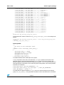
interrupt_group_table_entry_t bsp_interrupt_group_table [];
This describes the complete set of interrupt groups for a given system. It comprises a list of
interrupt_group_table_entry_t types. For example:
interrupt_group_table_entry_t bsp_interrupt_group_table [] =
{
{ &OS21_GRP_NMI, OS21_CTRL_NONE, 0, 0, 0 },
{ &OS21_GRP_IRL_ENCODED_15, OS21_CTRL_NONE, 0, 0, 15 },
{ &OS21_GRP_IRL_ENCODED_14, OS21_CTRL_NONE, 0, 0, 14 },
{ &OS21_GRP_IRL_ENCODED_13, OS21_CTRL_NONE, 0, 0, 13 },
{ &OS21_GRP_IRL_ENCODED_12, OS21_CTRL_NONE, 0, 0, 12 },
{ &OS21_GRP_IRL_ENCODED_11, OS21_CTRL_NONE, 0, 0, 11 },
{ &OS21_GRP_IRL_ENCODED_10, OS21_CTRL_NONE, 0, 0, 10 },
{ &OS21_GRP_IRL_ENCODED_9, OS21_CTRL_NONE, 0, 0, 9 },
{ &OS21_GRP_IRL_ENCODED_8, OS21_CTRL_NONE, 0, 0, 8 },
{ &OS21_GRP_IRL_ENCODED_7, OS21_CTRL_NONE, 0, 0, 7 },
{ &OS21_GRP_IRL_ENCODED_6, OS21_CTRL_NONE, 0, 0, 6 },
{ &OS21_GRP_IRL_ENCODED_5, OS21_CTRL_NONE, 0, 0, 5 },
{ &OS21_GRP_IRL_ENCODED_4, OS21_CTRL_NONE, 0, 0, 4 },
{ &OS21_GRP_IRL_ENCODED_3, OS21_CTRL_NONE, 0, 0, 3 },
{ &OS21_GRP_IRL_ENCODED_2, OS21_CTRL_NONE, 0, 0, 2 },
{ &OS21_GRP_IRL_ENCODED_1, OS21_CTRL_NONE, 0, 0, 1 },
{
{
{
{
{
{
{
{
{
{
{
{
14/23
&OS21_GRP_INTC_0, OS21_CTRL_INTC, 0, 0, 4 }, /* RTC */
&OS21_GRP_INTC_1, OS21_CTRL_INTC, 0, 1, 15 }, /* TMU 2 */
&OS21_GRP_INTC_2, OS21_CTRL_INTC, 0, 2, 15 }, /* TMU 1 */
&OS21_GRP_INTC_3, OS21_CTRL_INTC, 0, 3, 15 }, /* TMU 0 */
&OS21_GRP_INTC_4, OS21_CTRL_INTC, 1, 0, 0 }, /* NOT CONNECTED */
&OS21_GRP_INTC_5, OS21_CTRL_INTC, 1, 1, 14 }, /* SCIF 1 */
&OS21_GRP_INTC_6, OS21_CTRL_INTC, 1, 2, 0 }, /* NOT CONNECTED */
&OS21_GRP_INTC_7, OS21_CTRL_INTC, 1, 3, 15 }, /* WDT */
&OS21_GRP_INTC_8, OS21_CTRL_INTC, 2, 0, 15 }, /* HUDI */
&OS21_GRP_INTC_9, OS21_CTRL_INTC, 2, 1, 14 }, /* SCIF 2 */
&OS21_GRP_INTC_10, OS21_CTRL_INTC, 2, 2, 0 }, /* NOT CONNECTED */
&OS21_GRP_INTC_11, OS21_CTRL_INTC, 2, 3, 0 }, /* NOT CONNECTED */
7358673
OS21, ST40
Board support package
{
{
{
{
{
{
{
{
{
{
{
{
{
{
{
{
{
{
{
{
{
{
{
{
&OS21_GRP_INTC2_0, OS21_CTRL_INTC2, 0, 0, 10 }, /* PIO 0 */
&OS21_GRP_INTC2_1, OS21_CTRL_INTC2, 0, 1, 5 }, /* TTXT DMAC */
&OS21_GRP_INTC2_2, OS21_CTRL_INTC2, 0, 2, 5 }, /* DMAC */
&OS21_GRP_INTC2_3, OS21_CTRL_INTC2, 0, 3, 10 }, /* PIO 1 */
&OS21_GRP_INTC2_4, OS21_CTRL_INTC2, 0, 4, 0 }, /* NOT CONNECTED
&OS21_GRP_INTC2_5, OS21_CTRL_INTC2, 0, 5, 0 }, /* NOT CONNECTED
&OS21_GRP_INTC2_6, OS21_CTRL_INTC2, 0, 6, 0 }, /* NOT CONNECTED
&OS21_GRP_INTC2_7, OS21_CTRL_INTC2, 0, 7, 0 }, /* NOT CONNECTED
&OS21_GRP_INTC2_8, OS21_CTRL_INTC2, 1, 0, 13 }, /* ILC 0 */
&OS21_GRP_INTC2_9, OS21_CTRL_INTC2, 1, 1, 7 }, /* ILC 1 */
&OS21_GRP_INTC2_10, OS21_CTRL_INTC2, 1, 2, 13 }, /* ILC 2 */
&OS21_GRP_INTC2_11, OS21_CTRL_INTC2, 1, 3, 8 }, /* ILC 3 */
&OS21_GRP_INTC2_12, OS21_CTRL_INTC2, 1, 4, 14 }, /* ILC 4 */
&OS21_GRP_INTC2_13, OS21_CTRL_INTC2, 1, 5, 9 }, /* ILC 5 */
&OS21_GRP_INTC2_14, OS21_CTRL_INTC2, 1, 6, 6 }, /* ILC 6 */
&OS21_GRP_INTC2_15, OS21_CTRL_INTC2, 1, 7, 5 }, /* ILC 7 */
&OS21_GRP_INTC2_16, OS21_CTRL_INTC2, 2, 0, 9 }, /* ILC 8 */
&OS21_GRP_INTC2_17, OS21_CTRL_INTC2, 2, 1, 9 }, /* ILC 9 */
&OS21_GRP_INTC2_18, OS21_CTRL_INTC2, 2, 2, 4 }, /* ILC 10 */
&OS21_GRP_INTC2_19, OS21_CTRL_INTC2, 2, 3, 7 }, /* ILC 11 */
&OS21_GRP_INTC2_20, OS21_CTRL_INTC2, 2, 4, 8 }, /* ILC 12 */
&OS21_GRP_INTC2_21, OS21_CTRL_INTC2, 2, 5, 8 }, /* ILC 13 */
&OS21_GRP_INTC2_22, OS21_CTRL_INTC2, 2, 6, 8 }, /* ILC 14 */
&OS21_GRP_INTC2_23, OS21_CTRL_INTC2, 2, 7, 2 } /* ILC 15 */
*/
*/
*/
*/
};
unsigned int bsp_interrupt_group_table_entries;
This specifies the number of entries in bsp_group_interrupt_table. It is usually set as
follows:
unsigned int bsp_interrupt_group_table_entries = sizeof (bsp_interrupt_group_table)
/ sizeof
(interrupt_group_table_entry_t);
Interrupt table
/*
* An entry in the interrupt table.
*/
typedef struct interrupt_table_entry_s
{
interrupt_name_t * namep;
interrupt_group_t * groupp;
unsigned short intevt;
unsigned short bitpos;
} interrupt_table_entry_t;
This table describes all the interrupts in the system.
namep is a pointer to the name of the interrupt. groupp is a pointer to the name of the
interrupt group to which the interrupt belongs. intevt is the code that is placed in the
INTEVT register by the ST40 when the interrupt is asserted. bitpos is only used when the
interrupt belongs to the INTC2. In this case this gives the bit position of this interrupt within
the INTC2. For example:
interrupt_name_t OS21_MY_INTERRUPT = 21;
interrupt_table_entry_t my_interrupt = { &OS21_MY_INTERRUPT,
&OS21_MY_GROUP_3, 0x1240, 2 };
This describes an interrupt called OS21_MY_INTERRUPT which belongs to the interrupt
group OS21_MY_GROUP_3. This generates an INTEVT code of 0x1240 when it is asserted.
7358673
15/23
Board support package
OS21, ST40
Since OS21_MY_GROUP_3 belongs to the INTC2, this interrupt can be found in bit two of the
appropriate INTC2 registers.
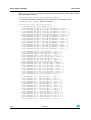
interrupt_table_entry_t bsp_interrupt_table [];
This describes the set of interrupts that arrive at the INTC. It comprises a list of
interrupt_table_entry_t types. For example:
interrupt_table_entry_t bsp_interrupt_table [] =
{
{ &OS21_INTERRUPT_NMI, &OS21_GRP_NMI, 0x01C0, 0 },
{ &OS21_INTERRUPT_IRL_ENC_15, &OS21_GRP_IRL_ENCODED_15, 0x0200,
{ &OS21_INTERRUPT_IRL_ENC_14, &OS21_GRP_IRL_ENCODED_14, 0x0220,
{ &OS21_INTERRUPT_IRL_ENC_13, &OS21_GRP_IRL_ENCODED_13, 0x0240,
{ &OS21_INTERRUPT_IRL_ENC_12, &OS21_GRP_IRL_ENCODED_12, 0x0260,
{ &OS21_INTERRUPT_IRL_ENC_11, &OS21_GRP_IRL_ENCODED_11, 0x0280,
{ &OS21_INTERRUPT_IRL_ENC_10, &OS21_GRP_IRL_ENCODED_10, 0x02A0,
{ &OS21_INTERRUPT_IRL_ENC_9, &OS21_GRP_IRL_ENCODED_9, 0x02C0, 0
{ &OS21_INTERRUPT_IRL_ENC_8, &OS21_GRP_IRL_ENCODED_8, 0x02E0, 0
{ &OS21_INTERRUPT_IRL_ENC_7, &OS21_GRP_IRL_ENCODED_7, 0x0300, 0
{ &OS21_INTERRUPT_IRL_ENC_6, &OS21_GRP_IRL_ENCODED_6, 0x0320, 0
{ &OS21_INTERRUPT_IRL_ENC_5, &OS21_GRP_IRL_ENCODED_5, 0x0340, 0
{ &OS21_INTERRUPT_IRL_ENC_4, &OS21_GRP_IRL_ENCODED_4, 0x0360, 0
{ &OS21_INTERRUPT_IRL_ENC_3, &OS21_GRP_IRL_ENCODED_3, 0x0380, 0
{ &OS21_INTERRUPT_IRL_ENC_2, &OS21_GRP_IRL_ENCODED_2, 0x03A0, 0
{ &OS21_INTERRUPT_IRL_ENC_1, &OS21_GRP_IRL_ENCODED_1, 0x03C0, 0
{
{
{
{
{
{
{
{
{
{
{
{
{
{
{
{
{
&OS21_INTERRUPT_HUDI_UDI, &OS21_GRP_INTC_8, 0x0600, 0 },
&OS21_INTERRUPT_TIMER_0, &OS21_GRP_INTC_3, 0x0400, 0 },
&OS21_INTERRUPT_TIMER_1, &OS21_GRP_INTC_2, 0x0420, 0 },
&OS21_INTERRUPT_TIMER_2, &OS21_GRP_INTC_1, 0x0440, 0 },
&OS21_INTERRUPT_TMU_2_TICPI, &OS21_GRP_INTC_1, 0x0460, 0 },
&OS21_INTERRUPT_RTC_ATI, &OS21_GRP_INTC_0, 0x0480, 0 },
&OS21_INTERRUPT_RTC_PRI, &OS21_GRP_INTC_0, 0x04A0, 0 },
&OS21_INTERRUPT_RTC_CUI, &OS21_GRP_INTC_0, 0x04C0, 0 },
&OS21_INTERRUPT_SCIF_1_ERI, &OS21_GRP_INTC_9, 0x04E0, 0 },
&OS21_INTERRUPT_SCIF_1_RXI, &OS21_GRP_INTC_9, 0x0500, 0 },
&OS21_INTERRUPT_SCIF_1_BRI, &OS21_GRP_INTC_9, 0x0520, 0 },
&OS21_INTERRUPT_SCIF_1_TXI, &OS21_GRP_INTC_9, 0x0540, 0 },
&OS21_INTERRUPT_SCIF_2_ERI, &OS21_GRP_INTC_5, 0x0700, 0 },
&OS21_INTERRUPT_SCIF_2_RXI, &OS21_GRP_INTC_5, 0x0720, 0 },
&OS21_INTERRUPT_SCIF_2_BRI, &OS21_GRP_INTC_5, 0x0740, 0 },
&OS21_INTERRUPT_SCIF_2_TXI, &OS21_GRP_INTC_5, 0x0760, 0 },
&OS21_INTERRUPT_WDT_ITI, &OS21_GRP_INTC_7, 0x0560, 0 },
{
{
{
{
{
{
{
{
{
{
{
{
{
{
{
{
&OS21_INTERRUPT_ILC_0, &OS21_GRP_INTC2_8, 0x1000, 0 },
&OS21_INTERRUPT_ILC_1, &OS21_GRP_INTC2_9, 0x1080, 4 },
&OS21_INTERRUPT_ILC_2, &OS21_GRP_INTC2_10, 0x1100, 8 },
&OS21_INTERRUPT_ILC_3, &OS21_GRP_INTC2_11, 0x1180, 12 },
&OS21_INTERRUPT_ILC_4, &OS21_GRP_INTC2_12, 0x1200, 16 },
&OS21_INTERRUPT_ILC_5, &OS21_GRP_INTC2_13, 0x1280, 20 },
&OS21_INTERRUPT_ILC_6, &OS21_GRP_INTC2_14, 0x1300, 24 },
&OS21_INTERRUPT_ILC_7, &OS21_GRP_INTC2_15, 0x1380, 28 },
&OS21_INTERRUPT_ILC_8, &OS21_GRP_INTC2_16, 0x1400, 0 },
&OS21_INTERRUPT_ILC_9, &OS21_GRP_INTC2_17, 0x1480, 4 },
&OS21_INTERRUPT_ILC_10, &OS21_GRP_INTC2_18, 0x1500, 8 },
&OS21_INTERRUPT_ILC_11, &OS21_GRP_INTC2_19, 0x1580, 12 },
&OS21_INTERRUPT_ILC_12, &OS21_GRP_INTC2_20, 0x1600, 16 },
&OS21_INTERRUPT_ILC_13, &OS21_GRP_INTC2_21, 0x1680, 20 },
&OS21_INTERRUPT_ILC_14, &OS21_GRP_INTC2_22, 0x1700, 24 },
&OS21_INTERRUPT_ILC_15, &OS21_GRP_INTC2_23, 0x1780, 28 },
};
16/23
7358673
},
0 },
0 },
0 },
0 },
0 },
},
},
},
},
},
},
},
},
},
OS21, ST40
Board support package
unsigned int bsp_interrupt_table_entries;
This specifies the number of entries in bsp_interrupt_table. It is usually set as follows:
unsigned int bsp_interrupt_table_entries = sizeof (bsp_interrupt_table) / sizeof
(interrupt_table_entry_t);
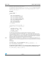
ILC table
/* ILC modes. */
typedef enum
{
OS21_ILC_NO_TRIGGER_0,
OS21_ILC_TRIGGER_HIGH_LEVEL,
OS21_ILC_TRIGGER_LOW_LEVEL,
OS21_ILC_TRIGGER_RISING_EDGE,
OS21_ILC_TRIGGER_FALLING_EDGE,
OS21_ILC_TRIGGER_ANY_EDGE,
OS21_ILC_NO_TRIGGER_1,
OS21_ILC_NO_TRIGGER_2,
OS21_ILC_TRIGGER_MAX
} ilc_mode_t;
/* An entry in the ILC table. */
typedef struct ilc_table_entry_s
{
interrupt_name_t * namep;
unsigned int input : 16;
unsigned int output : 16;
ilc_mode_t mode;
} ilc_table_entry_t;
This describes interrupts that are routed through an interrupt level controller.
namep is a pointer to the name of the interrupt. input is the number of the input into the
ILC that the interrupt arrives on. output is the number of the output to which the interrupt is
routed. mode describes how the interrupt is triggered. This table allows OS21 to locate the
appropriate state in the INTC2 which maps to the named interrupt.
Note:
Output 0 of the ILC must map to OS21_INTERRUPT_ILC_0 in the interrupt table and so on.
This enables OS21 to locate the appropriate state in the interrupt table that the ILC interrupt
maps to.
For example:
interrupt_name_t OS21_MY_INTERRUPT = 21;
ilc_table_entry_t my_interrupt = { &OS21_MY_INTERRUPT, 1, 15,
OS21_ILC_TRIGGER_RISING_EDGE };
This describes an interrupt called OS21_MY_INTERRUPT which is routed into input 1 of the
ILC and out on output 15. Line 15 out of the ILC is asserted on the rising edge of input 1.
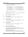
ilc_table_entry_t bsp_ilc_table [];
7358673
17/23
Board support package
OS21, ST40
This describes the set of interrupts that arrive at the ILC. It comprises a list of
ilc_table_entry_t types. For example:
ilc_table_entry_t bsp_ilc_table[] =
{
{ &OS21_INTERRUPT_PIO_0, 0, 0, OS21_ILC_TRIGGER_HIGH_LEVEL },
{ &OS21_INTERRUPT_SSC_0, 7, 1, OS21_ILC_TRIGGER_HIGH_LEVEL },
{ &OS21_INTERRUPT_DMA_0, 24, 10, OS21_ILC_TRIGGER_HIGH_LEVEL },
{ &OS21_INTERRUPT_DMA_1, 25, 10, OS21_ILC_TRIGGER_HIGH_LEVEL },
{ &OS21_INTERRUPT_DMA_2, 26, 10, OS21_ILC_TRIGGER_HIGH_LEVEL },
{ &OS21_INTERRUPT_DMA_3, 27, 10, OS21_ILC_TRIGGER_HIGH_LEVEL },
{ &OS21_INTERRUPT_DMA_4, 28, 10, OS21_ILC_TRIGGER_HIGH_LEVEL },
{ &OS21_INTERRUPT_DMA_ERR, 29, 10, OS21_ILC_TRIGGER_HIGH_LEVEL }
};
unsigned int bsp_ilc_table_entries;
This variable specifies the number of entries in bsp_ilc_table. It is usually set as follows:
unsigned int bsp_ilc_table_entries = sizeof (bsp_ilc_table) / sizeof
(ilc_table_entry_t);
Note:
If an ILC is not present on a given target, bsp_ilc_table and
bsp_ilc_table_entries must be removed.
6.2.4
INTC base address
This tells OS21 the base address of the first interrupt controller (INTC). For example:
void * bsp_intc_base_address
6.2.5
= (void *)(0xFFD00000);
INTC2 base address
This tells OS21 the base address of the second interrupt controller (INTC2). For example:
void * bsp_intc2_base_address = (void *)(0xFE080000);
If INTC2 does not exist, remove this line.
6.2.6
ILC base address
This tells OS21 the base address of the ILC memory mapped registers. For example:
void * bsp_ilc_base_address = (void *)(0x18300000);
If no ILC is present, remove this line.
6.2.7
Interrupt system initialization flags
interrupt_init_flags_t bsp_interrupt_init_flags;
This is a combination of flags which is used to control how OS21 initializes the interrupt
subsystem. Multiple flags can be combined by logically ORing the appropriate flags. The
following sections describe the valid flags for ST40.
Nonmaskable interrupt trigger mode
The interrupt controller (INTC) on the ST40 can be programmed so the nonmaskable
interrupt (NMI) generates an interrupt either on the rising edge or the falling edge of the NMI
18/23
7358673
OS21, ST40
Board support package
signal. The following flags tell OS21 how to configure INTC in this respect. If none of these
flags are specified, OS21 defaults to triggering on the falling edge. If both are specified,
OS21 defaults to triggering on the rising edge.
OS21_INTC_NMI_RISING_EDGE
This tells OS21 to program the INTC so that an NMI is generated on the rising edge of
the NMI signal (when it transitions to the high state).
OS21_INTC_NMI_FALLING_EDGE
This tells OS21 to program the INTC so that an NMI is generated on the falling edge of
the NMI signal (when it transitions to the low state).
IRL configuration mode
The interrupt controller (INTC) on the ST40 can accomodate four external interrupt request
lines (IRL). These can be configured either as four separate interrupt lines (giving four
interrupt sources) or as a binary encoding of 15 different interrupts by using each of the four
interrupt lines as a binary bit. The following flags tell OS21 how the INTC should be
configured in this respect. If neither of these flags are specified, OS21 defaults to four
separate IRL lines. If both flags are specified, OS21 defaults to the encoding mechanism.
OS21_INTC_IRL_LEVEL_ENCODED
This tells OS21 to program the INTC so that it treats the four IRL lines as a level
encoding of 15 different interrupts.
OS21_INTC_IRL_INDIVIDUAL
This tells OS21 to program the INTC so that it treats the four IRL lines as four separate
interrupt request lines.
Interrupt level controller programming
On multiple CPU systems, more than one CPU shares access to the interrupt level
controller (ILC). However only one CPU should take responsibility for programming the ILC
at start up time - normally the “master” of the system. The following flags tell OS21 whether
it should program the ILC as a master, or program the ILC as a slave. If none of these flags
are specified, OS21 defaults to being an ILC master. If both of these flags are specified,
OS21 defaults to being an ILC slave.
OS21_ILC_MASTER
This tells OS21 that this CPU is responsible for the programming of the interrupt level
controller. When OS21 initializes the interrupt subsystem it programs the ILC as given
in the table.
OS21_ILC_SLAVE
This tells OS21 that this CPU is not responsible for the programming of the interrupt
level controller. When OS21 initializes the interrupt subsystem it does not program the
ILC as given in the table.
7358673
19/23
Revision history
7
OS21, ST40
Revision history
Table 5.
Document revision history
Date
Revision
1-Oct-2009
O
Changes made to Section 6.2: BSP interrupt system description on
page 12.
10-Nov-2008
N
Added Chapter 5: Constructors and destructors on page 11.
12-Nov-2007
M
Moved the generic elements of the board support package to the
OS21 User manual (ADCS 7358306).
15-May-2007
L
Moved cache API functions to OS21 User manual (ADCS 7358306)
as these are now generic.
K
Moved to new template.
Chapter 1: Caches and memory areas on page 5: Updated for virtual
memory 32-bit support.
Chapter 6: Board support package on page 12: Timer input freq
updated.
Jun 06
J
Throughout: Updated function context information.
Caches and memory areas chapter: Updated I-cache and D-cache
descriptions and explained non-portable code for ST40 core
variants.
Exceptions chapter: Removed chapter.
Sep 03
I
Board support package chapter: Updated BSP interrupt system
description, Interrupt tables and Interrupt system initialization flags.
Jul 03
H
Floating point support chapter: Chapter has been rewritten.
Board support package chapter: Updated BSP data, Timer input
frequency.
G
Throughout: Changed _bsp_peripheral_bus_clock_frequency_hz to
bsp_timer_input_clock_frequency_hz, _bsp_timeslice_frequency_hz
to bsp_timeslice_frequency_hz and peripheral bus clock to input
clock. Updated references to interrupts.
Introduction chapter: Added note to ST40 specifics.
Interrupts chapter: Removed chapter.
Caches and memory areas chapter: Updated cache_enable_data
function description. Added note to cache_invalidate_data_all.
Timers chapter: Chapter has been rewritten.
Resets chapter: Updated examples in Overview,
Board support package chapter: Chapter has been rewritten.
22-Jan-2007
May 03
20/23
Changes
7358673
OS21, ST40
Revision history
Table 5.
Date
Document revision history (continued)
Revision
Changes
F
Throughout: Added Context section to each of the functions.
Interrupts chapter: Changed description of interrupts_mask() in the
Masking interrupts section.
Caches and memory areas chapter: Added cache_status_flags_t to
Table 6. Corrected typing errors in Table 7. In the cache_enable_data
and cache_enable_instruction functions, changed the names of the
assigned bits to upper case. Updated cache_status function.
Board support package chapter: Added footnote for ST40GX1
Evaluation board. In the BSP code section, added bsp_terminate()
and changed the description of bsp_shutdown().
E
Interrupts chapter: Added a new function, interrupt_mask_all(), and
added cross-references to it. Updated the functions, interrupt_mask()
and interrupt_unmask(). Removed references to 7750.
Exceptions chapter: Changed description of default behavior in last
paragraph of overview.
Board support package chapter: Updated the location of the BSPs
for ST40 platforms.
D
Throughout: Added _bsp_ to the start of timeslice_frequency_hz and
peripheral_bus_clock_frequency_hz.
Board support package chapter: Changed board names to product
names.
C
Interrupts chapter: Changed description of ST40_GRP_7750_SCI_1
and ST40_GRP_7750_SCIF in the ST40 interrupt source names
table.
Caches and memory areas chapter: Added note to caches and
memory overview.
Floating point support chapter: Amended text in overview.
Board support package chapter: Added two functions to BSP code
section.
Feb 02
B
Introduction chapter: Added the “ST40 specifics” section.
Interrupts chapter: Added the “task_context() interrupt information”
section. Amended description of the flags parameter in the
“Initializing the interrupt handling subsystem” section. Amended the
description of the interrupt_init_controller function.
Caches and memory areas chapter: Amended the table containing
the macros defined in st40_cache.h.
Board support package chapter: Amended the “BSP code” section.
Nov 01
A
Initial release
Aug 02
Aug 02
May 02
May 02
7358673
21/23
Index
OS21, ST40
Index
B
Backus-Naur Form . . . . . . . . . . . . . . . . . . . . . . .4
base address . . . . . . . . . . . . . . . . . . . . . . . . . .18
BNF. See Backus-naur Form.
BSP
interrupt system . . . . . . . . . . . . . . . . . . . . . . .12
interrupt tables . . . . . . . . . . . . . . . . . . . . . . .12
F
floating point support . . . . . . . . . . . . . . . . . . . . .7
FPU . . . . . . . . . . . . . . . . . . . . . . . . . . . . . . . . . .7
resets . . . . . . . . . . . . . . . . . . . . . . . . . . . . . . . . . 9
RTC . . . . . . . . . . . . . . . . . . . . . . . . . . . . . . . . . . 5
S
ST40
specifics . . . . . . . . . . . . . . . . . . . . . . . . . . . . . 1
system stack size . . . . . . . . . . . . . . . . . . . . . . 1
timer assignments . . . . . . . . . . . . . . . . . . . . . 5
system stack size . . . . . . . . . . . . . . . . . . . . . . . 1
system timer . . . . . . . . . . . . . . . . . . . . . . . . . . . 5
T
G
GCC . . . . . . . . . . . . . . . . . . . . . . . . . . . . . . . . . .7
global context registers . . . . . . . . . . . . . . . . . . .8
I
ILC base address . . . . . . . . . . . . . . . . . . . . . . .18
ILC table . . . . . . . . . . . . . . . . . . . . . . . . . . . . . .17
initialization flags . . . . . . . . . . . . . . . . . . . . . . .18
input clock . . . . . . . . . . . . . . . . . . . . . . . . . . . . .5
determining speed . . . . . . . . . . . . . . . . . . . . . .5
interrupt groups . . . . . . . . . . . . . . . . . . . . . . . .13
interrupt level controller . . . . . . . . . . . . . . .13, 17
interrupt names . . . . . . . . . . . . . . . . . . . . . . . .12
interrupt system . . . . . . . . . . . . . . . . . . . . . . . .12
interrupt system initialization flags . . . . . . . . . .18
interrupt tables . . . . . . . . . . . . . . . . . . . . . . . . .13
task context registers . . . . . . . . . . . . . . . . . . . . 8
timeout timer . . . . . . . . . . . . . . . . . . . . . . . . . . . 6
timer assignments . . . . . . . . . . . . . . . . . . . . . . . 5
timers . . . . . . . . . . . . . . . . . . . . . . . . . . . . . . . . . 5
timeslice timer . . . . . . . . . . . . . . . . . . . . . . . . . . 5
TMU . . . . . . . . . . . . . . . . . . . . . . . . . . . . . . . . . . 5
TMU0 . . . . . . . . . . . . . . . . . . . . . . . . . . . . . . . . . 5
TMU1 . . . . . . . . . . . . . . . . . . . . . . . . . . . . . . . . . 5
TMU2 . . . . . . . . . . . . . . . . . . . . . . . . . . . . . . . . . 5
W
watchdog timer . . . . . . . . . . . . . . . . . . . . . . . . . 9
L
linker error . . . . . . . . . . . . . . . . . . . . . . . . . . . .12
M
manual reset . . . . . . . . . . . . . . . . . . . . . . . . . . .9
O
OS21 kernel
building . . . . . . . . . . . . . . . . . . . . . . . . . . . . . .7
OS21 tick duration . . . . . . . . . . . . . . . . . . . . . . .5
R
register context . . . . . . . . . . . . . . . . . . . . . . . . . .8
22/23
7358673 Rev O
OS21, ST40
Please Read Carefully:
Information in this document is provided solely in connection with ST products. STMicroelectronics NV and its subsidiaries (“ST”) reserve the
right to make changes, corrections, modifications or improvements, to this document, and the products and services described herein at any
time, without notice.
All ST products are sold pursuant to ST’s terms and conditions of sale.
Purchasers are solely responsible for the choice, selection and use of the ST products and services described herein, and ST assumes no
liability whatsoever relating to the choice, selection or use of the ST products and services described herein.
No license, express or implied, by estoppel or otherwise, to any intellectual property rights is granted under this document. If any part of this
document refers to any third party products or services it shall not be deemed a license grant by ST for the use of such third party products
or services, or any intellectual property contained therein or considered as a warranty covering the use in any manner whatsoever of such
third party products or services or any intellectual property contained therein.
UNLESS OTHERWISE SET FORTH IN ST’S TERMS AND CONDITIONS OF SALE ST DISCLAIMS ANY EXPRESS OR IMPLIED
WARRANTY WITH RESPECT TO THE USE AND/OR SALE OF ST PRODUCTS INCLUDING WITHOUT LIMITATION IMPLIED
WARRANTIES OF MERCHANTABILITY, FITNESS FOR A PARTICULAR PURPOSE (AND THEIR EQUIVALENTS UNDER THE LAWS
OF ANY JURISDICTION), OR INFRINGEMENT OF ANY PATENT, COPYRIGHT OR OTHER INTELLECTUAL PROPERTY RIGHT.
UNLESS EXPRESSLY APPROVED IN WRITING BY AN AUTHORIZED ST REPRESENTATIVE, ST PRODUCTS ARE NOT
RECOMMENDED, AUTHORIZED OR WARRANTED FOR USE IN MILITARY, AIR CRAFT, SPACE, LIFE SAVING, OR LIFE SUSTAINING
APPLICATIONS, NOR IN PRODUCTS OR SYSTEMS WHERE FAILURE OR MALFUNCTION MAY RESULT IN PERSONAL INJURY,
DEATH, OR SEVERE PROPERTY OR ENVIRONMENTAL DAMAGE. ST PRODUCTS WHICH ARE NOT SPECIFIED AS "AUTOMOTIVE
GRADE" MAY ONLY BE USED IN AUTOMOTIVE APPLICATIONS AT USER’S OWN RISK.
Resale of ST products with provisions different from the statements and/or technical features set forth in this document shall immediately void
any warranty granted by ST for the ST product or service described herein and shall not create or extend in any manner whatsoever, any
liability of ST.
ST and the ST logo are trademarks or registered trademarks of ST in various countries.
Information in this document supersedes and replaces all information previously supplied.
The ST logo is a registered trademark of STMicroelectronics. All other names are the property of their respective owners.
© 2009 STMicroelectronics - All rights reserved
STMicroelectronics group of companies
Australia - Belgium - Brazil - Canada - China - Czech Republic - Finland - France - Germany - Hong Kong - India - Israel - Italy - Japan Malaysia - Malta - Morocco - Philippines - Singapore - Spain - Sweden - Switzerland - United Kingdom - United States of America
www.st.com
7358673 Rev O
23/23